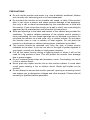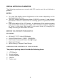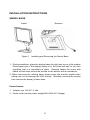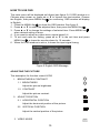
1
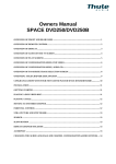
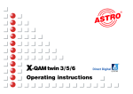
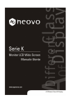
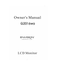
Contents
CERTIFICATIONS -------------------------------------------------------------------NOTICE ---------------------------------------------------------------------------------PRECAUTIONS ---------------------------------------------------------------SPECIAL NOTES ON LCD MONITORS ---------------------------------
2
2
3
4
BEFORE YOU OPERATE THE MONITOR ------------------------------------FEATURES ---------------------------------------------------------------------PACKING LIST ----------------------------------------------------------------INSTALLATION INSTRUCTIONS-----------------------------------------CONTROLS AND CONNECTORS ---------------------------------------ADJUSTING THE VIEWING ANGLE -------------------------------------
4
4
4
5
6
7
OPERATING INSTRUCTIONS ----------------------------------------------------- 8
GENERAL INSTRUCTIONS ------------------------------------------------ 8
HOW TO USE OSD ----------------------------------------------------------- 10
ADJUSTING THE PICTURE -------------------------------------------- 10-11
GREEN MONITOR------------------------------------------------------------ 12
PLUG AND PLAY ------------------------------------------------------------- 12
TECHNICAL SUPPORT(FAQ) ------------------------------------------------- 13-14
ERROR MESSAGE & POSSIBLE SOLUTION ---------------------- 15
APPENDIX A SPECIFICATIONS ----------------------------------------- 16
APPENDIX B FACTORY PRESET TIMING TABLE ----------------- 17
APPENDIX C CONNECTOR PIN ASSIGNMENT -------------------- 18
Notice:
Please read the following words before assembling and using this monitor.
Any reference to an Lenovo product, program or service is not intended to
state or imply that only Lenovo ’s product, program, or service may be used.
Any functionally equivalent product, program, or service that does not infringe
any of Lenovo’s intellectual property rights or other legally protectable rights
may be used instead of the Lenovo product, program, or service. Evaluation
and verification of operation in conjunction with other products, programs, or
services, except those expressly designated by Lenovo, are the user’s
responsibility.
Lenovo may have patents or pending patent applications covering subject
matter in this document. The furnishing of this document does not give you
any license to these patents.
Information in this document is subject to change without notice.
Without the permission of Lenovo (Beijing) Limited, no part of this manual may
be reproduced or distributed in any form or by any means.
lenovo® is a lenovo (Beijing) Limited registered trademark.
1
CE certificate
This shipped version of this device complies with the
requirements of the EEC directive 89/336/EEC
“Electromagnetic compatibility” and 73/23/EEC “Low
voltage directive”.
FCC Class B Radio Frequency Interference Statement
WARNING: (FOR FCC CERTIFIED MODELS)
NOTE: This equipment has been tested and found to comply with the limits for
a Class B digital device, pursuant to Part 15 of the FCC Rules. These limits
are designed to provide reasonable protection against harmful interference in
a residential installation. This equipment generates, uses and can radiate
radio frequency energy, and if not installed and used in accordance with the
instructions, may cause harmful interference to radio communications.
However, there is no guarantee that interference will not occur in a particular
installation. If this equipment does cause harmful interference to radio or
television reception, which can be determined by turning the equipment off
and on, the user is encouraged to try to correct the interference by one or
more of the following measures:
1. Reorient or relocate the receiving antenna.
2. Increase the separation between the equipment and receiver.
3. Connect the equipment into an outlet on a circuit different from that to
which the receiver is connected.
4. Consult the dealer or an experienced radio/TV technician for help.
NOTICE:
1.
2.
1.
The changes or modifications not expressly approved by the party
responsible for compliance could void the user's authority to operate the
equipment.
Shielded interface cables and AC power cord, if any, must be used in
order to comply with the emission limits.
The manufacturer is not responsible for any radio or TV interference
caused by unauthorized modification to this equipment. It is the
responsibilities of the user to correct such interference.
WARNING:
To prevent fire or shock hazard, do not expose the monitor to rain or moisture.
Dangerously high voltages are present inside the monitor. Do not open the
cabinet. Refer servicing to qualified personnel only.
2
PRECAUTIONS
z Do not use the monitor near water, e.g. near a bathtub, washbowl, kitchen
sink, laundry tub, swimming pool or in a wet basement.
z Do not place the monitor on an unstable cart, stand, or table. If the monitor
falls, it can injure a person and cause serious damage to the appliance.
Use only a cart or stand recommended by the manufacturer or sold with
the monitor. If you mount the monitor on a wall or shelf, use a mounting kit
approved by the manufacturer and follow the kit instructions.
z Slots and openings in the back and bottom of the cabinet are provided for
ventilation. To ensure reliable operation of the monitor and to protect it
from overheating, be sure these openings are not blocked or covered. Do
not place the monitor on a bed, sofa, rug, or similar surface. Do not place
the monitor near or over a radiator or heat register. Do not place the
monitor in a bookcase or cabinet unless proper ventilation is provided.
z The monitor should be operated only from the type of power source
indicated on the label. If you are not sure of the type of power supplied to
your home, consult your dealer or local power company.
z Cut off the power source during a lightning storm or when it will not be
used for long periods of time. This will protect the monitor from damage
due to power surges.
z Do not overload power strips and extension cords. Overloading can result
in fire or electric shock.
z Never push any object into the slot on the monitor cabinet. It could short
circuit parts causing a fire or electric shock. Never spill liquids on the
monitor.
z Do not attempt to service the monitor yourself, opening or removing covers
can expose you to dangerous voltages and other hazards. Please refer all
servicing to qualified service personnel.
3
SPECIAL NOTES ON LCD MONITORS
The following symptoms are normal with LCD monitor and do not indicate a
problem.
NOTES
• You may find slightly uneven brightness on the screen depending on the
desktop pattern you use.
• The LCD screen has effective pixels of 99.99% or more. It may include
•
blemishes of 0.01% or less such as a missing pixel or a pixel lit all of the
time.
Due to the nature of the LCD screen, an afterimage of the previous screen
may remain after switching the image, when the same image is displayed
for hours. In this case, the screen is recovered slowly by changing the
image or turning off the Power for hours.
BEFORE YOU OPERATE THE MONITOR
FEATURES
•
•
•
•
•
43.2cm(17”) TFT Color LCD Monitor
Optimal Resolutions is 1280 X 1024@60Hz
Low Power Consume & Power Saving Design
Ergonomic Design
Space Saving, Compact Case Design
CHECKING THE CONTENTS OF THE PACKAGE
The product package should include the following items:
1.
2.
3.
4.
5.
LCD Monitor
Monitor’s Base
Owner's Manual
Adapter
Power cord
4
INSTALLATION INSTRUCTIONS
SWIVEL BASE
Install
Figure 1
Remove
Installing and Removing the Swivel Base
1. During installation, place the display base the right-way up on a flat surface.
Place upper part of the display slowly on to the base and wait for the click
signifying that it is completely in place. Securely fasten the screw with
hands or tools then secure the screws on the bottom with a screwdriver.
2. When removing the rotating base, please place the monitor upside down
taking care not to damage the LCD surface. Manually unscrew the screws
then remove the display’s lower base.
Power Source:
1. Adapter use 12V DC, 4.16A.
2. Power cord user the power supply(90V-264V AC Voltage)
5
CONTROLS AND CONNECTORS
Adapter
Connecting the adapter: Connect one end of the adapter to back of the
monitor and connect the other end to the power cord.
Power cord
Connecting the power cord: Connect one end of the power cord to the AC
adapter and connect the other end to the power supply (90V-264V AC
Voltage).
SIGNAL CABLE
Connecting the Signal Cable: the LCD monitor comes with a built-in video
cable. Plug the signal cable′s 15-pin connector into the computer's video port
and tighten the two screws on the cable connector.
1
Figure 2
1.
2
Connecting Cables
AC Adapter & Power cord
2.
6
Signal Cable
ADJUSTING THE VIEWING ANGLE
• For optimal viewing it is recommended to look at the full face of the
monitor, then adjust the monitor’s angle to your own preference.
• Hold the stand so you do not topple the monitor when you change the
monitor’s angle.
• You are able to adjust the monitor’s angle from -5° to 20°.
20°
-5°
Figure 3
NOTES
• Do not touch the LCD screen when you change the angle. It may cause
damage or break the LCD screen.
• Careful attention is required not to catch your fingers or hands when you
change the angle.
7
OPERATING INSTRUCTIONS
GENERAL INSTRUCTIONS
Press the power switch to turn the monitor on or off. The other control knobs
are located at front panel of the monitor (See Figure 4). By changing these
settings, the picture can be adjusted to your personal preferences.
Figure 4
External Control Button
EXTERNAL CONTROLS
1.
Auto Config / Exit
3. ▼/ Contrast
5. Power / Power indicator
2. ▲/ Brightness
4.
MENU / ENTER
8
FRONT PANEL CONTROL
• Power / Power indicator :
Press this knob to switch ON/OFF of monitor’s power. and display the
monitor’s state.
Blue — Power On mode.
Orange — Power Off mode.
• MENU/ENTER / :
Activate OSD menu or function adjusts confirmation.
• Contrast / ▼:
Adjust contrast or function adjustment.
• Brightness
/ ▲:
Adjust brightness or function adjustment.
• Auto Config Key / EXIT/ :
1. When OSD menu is in active status, this knob will act as EXIT-KEY
(EXIT OSD menu).
2. When OSD menu is in off status, press this knob over 1 seconds to be
in Auto Adjustment function.
The Auto Adjustment function is used to set the HPos, VPos, Clock and
Focus automatically.
NOTES
• Do not install the monitor in a location near heat sources such as radiators
•
•
•
•
or air ducts, or in a place subject to direct sunlight, or excessive dust or
mechanical vibration or shock.
Save the original shipping carton and packing materials, as they will come
in handy if you ever have to ship your monitor.
For maximum protection, repackage your monitor as it was originally
packed at the factory.
To keep the LCD clean, periodically clean it with a soft cloth. Any kind of
liquids will damage the LCD.
To keep the monitor looking new, periodically clean it with a soft cloth.
Stubborn stains may be removed with a cloth lightly dampened with a mild
detergent solution. Never use strong solvents such as thinner, benzene, or
abrasive cleaners, since these will damage the cabinet. As a safety
precaution, always unplug the monitor before cleaning it.
9
HOW TO USE OSD
The main menu will be displayed as follows (see figure 5). If OSD window is in
Chinese when power on, press ▲ or ▼ to choose the next window. Choose
the English, then press MENU Key . for confirming. OSD window will display
in English.
1. Press the MENU-Key . to show the OSD window. See figure 5.
2. Press ▲ or ▼ to select the adjusted item, then press the MENU-key .
3. Press ▲ or ▼ to change the settings of selected item. Press MENU-key .
when desired setting is done.
4. If you want to adjust any other items, repeat steps 2-4.
5. To exit and save the setting, press ▲ or ▼ to the exit item and press
MENU-key , or leave the monitor alone for 10 seconds.
6. When the OSD window is active, it shows the input signal timing.
Figure 5 English OSD Message
ADJUSTING THE PICTURE
The description for function control LEDS
1. BRIGHTNESS & CONTRAST
1.1 BRIGHTNESS
Adjust the picture brightness.
1.2 CONTRAST
Adjust the picture contrast.
2. ADJUST POSITION
2.1 HORIZONTAL POSITION
Adjust the horizontal position of the picture.
2.2 VERTICAL POSITION
Adjust the vertical position of the picture.
3. VIDEO NOISE
10
3.1 FOCUS
Adjust the picture Focus.
3.2 CLOCK
Adjust the picture Clock.
4. LANGUAGE
Multi-Language selection.
5. OSD TIMER
Choose OSD window display time.
6.
COLOR TEMPERATURE
6.1 7800K/6500K (COLOR TEMPERATURE)
The color temperature for 7800K is x=0.296, y=0.311
and 6500K is x=0.313, y=0.329. It presents two
different color sets on the screen. You can select
7800K or 6500K by pressing MENU Key.
6.2 USER MODE (Red / Green/ Blue)
If the 7800K normal white or 6500K warmer white do
not satisfy your desire, properly adjust R .G. B GAIN
controls to obtain your optimum whiteness level.
7.
OSD POSITION
7.1 HORIZINTAL OSD
Adjust the horizontal position of the OSD Menu.
7.2 VERTICAL OSD
Adjust the vertical position of the OSD Menu.
8. EXIT OSD
Close OSD window.
9.
RESET
Press RESET to restore the monitor to factory settings.
11
Green monitor
• The monitor has a power saving function that conforms to the VESA
standard. When the computer input no signal, the monitor will enter the
shuts off mode.
The power-saving mode can be indicated by the light-emitting diode (LED)
on the front panel:
Signal
Power
Mode
Cable
Picture
Indicator
Consumption
On
Attached
Active
Blue
≤ 42 W
Off
Attached
None
Orange
≤ 2W
Off
No attached
None
Orange
≤ 2W
PLUG AND PLAY
Plug & Play DDC2B Feature
This monitor is equipped with VESA DDC2B capabilities according to the
VESA DDC STANDARD. It allows the monitor to inform the host system of its
identity and, depending on the level of DDC used, communicate additional
information about its display capabilities.
The DDC2B is a bidirectional data channel based on the I²C protocol. The
host can request EDID information over the DDC2B channel.
12
TECHNICAL SUPPORT (FAQ)
Problem & Question
Power LED is not on
No picture, the LED indicator is
light up
Picture is gray
Picture bounces or a wave
pattern is present in the picture
Picture is fuzzy
Missing one of the primary
colors (RED, GREEN, or
BLUE)
Possible Solution
*Check if the Power Switch is in the ON
position
*Power Cord should be connected
*Check the Power socket.
*Replace new Power Cord.
*The Signal Cable should be completely
connected to the computer.
*If it is orange, then the monitor and the
computer are in dormancy mode. You
need press your keyboard or move the
mouse to reactivate the system.
*If it is blue, please adjust the
brightness and contrast by OSD menu.
*Check that the computer is switched on.
*Check that the signal’s pin are bent or
broke.
*adjust the brightness and contrast
controls.
*Move electrical devices that may cause
electrical interference.
*17” LCD monitor’s true (physical)
resolution is 1280 x 1024. Under the
resolution, it will get the best display.
*Inspect the monitor’s video cable and
make sure that none of the pins are
bent or broke (the pin’s number
reference to figure 6)
13
Screen image is not centered or *Adjust pixel frequency (CLOCK) and
sized properly.
FOCUS or press hot-key (AUTO).
Picture has color defects
*Adjust RGB color or select color
(white does not look white)
temperature
Poor brightness or contrast
*When the brightness of the screen
lowers after being used for a certain
period and the function of the display
is affected, send it to our authorized
service center for repair.
Horizontal or vertical disturbancies *Use Win 95/98/2000/ME shutdown
on the screen
mode Adjust CLOCK and FOCUS or
perform hot- key (AUTO-key).
CLOCK (pixel frequency) controls the number of pixels scanned by one
horizontal sweep. If the frequency is not correct, the screen shows vertical
stripes and the picture has not correct width.
FOCUS adjust the phase of the pixel clock signal. With a wrong phase
adjustment the picture has horizontal disturbances in light picture.
For FOCUS and CLOCK adjustment use Win 95/98/2000/ME shutdown mode
pattern.
14
ERROR MESSAGE & POSSIBLE SOLUTION
NO SIGNAL INPUT
1.
2.
The computer is switched off.
The computer is dormancy.
CABLE NOT CONNECTED :
1.
2.
Check that the signal-cable is properly connected, If the connector is
loose, tighten the connector’s screws.
Check the signal-cable’s connection pins for damage.
INPUT THE RESOLUTION OUT OF THE RANGE:
Your computer has been set to unsuitable display mode, Set the computer to
display mode given in the following table.
15
APPENDIX A
SPECIFICATIONS
LCD Panel
Input
Type
Size
Pixel pitch
Video
Separate Sync.
H-Frequency
V-Frequency
Display Colors
Dot Clock
Max. Resolution
Plug & Play
Input Connector
Input Video Signal
Maximum Screen Size
Power Source
Environmental
Considerations
Weight (N. W.)
Power Consumption
Regulatory Compliance
16
TFT Color LCD
43.2cm(17")
0.264mm( H ) x 0.264mm( V )
R,G,B Analog Interface
H/V TTL
30kHz - 80kHz
50Hz-75Hz
16.2M Colors
135MHz
1280 x 1024
VESA DDC2BTM
D-Sub 15pin
Analog:0.7Vp-p(standard),
75 OHM, Positive
Horizontal : 337.92mm
Vertical : 270.34mm
12V DC, 3.5A
Operating Temp.:
0°C to +40°C (32°F to 104°F)
Storage Temp.:
-20°C to 60°C (-4°F to 140°F)
Operating Humidity :
10% to 85%
4.5kg
42 Watts
CCC,TCO’95
APPENDIX B
FACTORY PRESET TIMING TABLE
STANDARD
RESOLUTION
HORIZONTAL
FREQUENCY
VERTICAL
FREQUENCY
Dos-modo
720 × 400
31.47kHz
70Hz
640 × 480
31.47kHz
60Hz
640 × 480
37.861kHz
72Hz
640 × 480
37.50kHz
75Hz
800 × 600
37.879kHz
60Hz
800 × 600
48.077kHz
72Hz
800 × 600
46.875kHz
75Hz
1024 × 768
48.363kHz
60Hz
1024 × 768
56.476kHz
70Hz
1024 × 768
60.02kHz
75Hz
1280 × 1024
64.000kHz
60Hz
1280 × 1024
80.000kHz
75Hz
VGA
SVGA
XGA
SXGA
17
APPENDIX C
CONNECTOR PIN ASSIGNMENT
1
5
6
10
11
15
Figure 6 15 - Pin Color Display Signal Cable
PIN NO.
1.
2.
3.
4.
5.
6.
7.
8.
DESCRIPTION
PIN NO.
DESCRIPTION
9.
10.
11.
12.
13.
14.
15.
+5V
Ground
Ground
DDC-Serial Data
H-Sync
V-Sync
DDC-Serial Clock
Red
Green
Blue
Ground
Ground
R-Ground
G-Ground
B-Ground
18