1
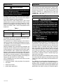
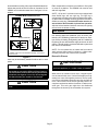
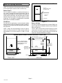
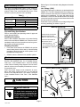
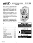
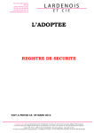
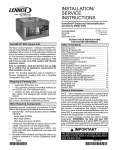
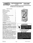
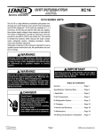
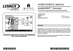
INSTALLATION
INSTRUCTIONS
E2006 Lennox Industries Inc.
Dallas, Texas, USA
CBWMV Series Units
AIR HANDLERS
505,047M
09/06
Supersedes 02/06
Litho U.S.A.
Table of Contents
Introduction . . . . . . . . . . . . . . . . . . . . . . . . . . . . . . . . . . .
Shipping & Packing List . . . . . . . . . . . . . . . . . . . . . . . .
CBWMV Unit Dimensions . . . . . . . . . . . . . . . . . . . . . .
General . . . . . . . . . . . . . . . . . . . . . . . . . . . . . . . . . . . . . .
CBWMV Unit Parts Arrangement . . . . . . . . . . . . . . . .
CBWMV Unit Parts Description . . . . . . . . . . . . . . . . . .
CBWMV Unit Optional Accessories . . . . . . . . . . . . . .
Requirements . . . . . . . . . . . . . . . . . . . . . . . . . . . . . . . . .
Application . . . . . . . . . . . . . . . . . . . . . . . . . . . . . . . . . . .
Installation − Setting Equipment . . . . . . . . . . . . . . . . . .
Duct System . . . . . . . . . . . . . . . . . . . . . . . . . . . . . . . . . .
Return Air Opening Guidelines . . . . . . . . . . . . . . . . . .
Filter Assembly & Filters . . . . . . . . . . . . . . . . . . . . . . .
Plumbing . . . . . . . . . . . . . . . . . . . . . . . . . . . . . . . . . . . . .
Electrical . . . . . . . . . . . . . . . . . . . . . . . . . . . . . . . . . . . . .
Freezestat Operation . . . . . . . . . . . . . . . . . . . . . . . . . .
BDC3 Variable Blower Control Board . . . . . . . . . . . . .
Blower Speed Adjustments . . . . . . . . . . . . . . . . . . . . .
Initial Air System Purging . . . . . . . . . . . . . . . . . . . . . . .
System Adjustments . . . . . . . . . . . . . . . . . . . . . . . . . . .
Annual Service . . . . . . . . . . . . . . . . . . . . . . . . . . . . . . . .
Service Filters . . . . . . . . . . . . . . . . . . . . . . . . . . . . . . . .
Winterizing the CBWMV Unit . . . . . . . . . . . . . . . . . . . .
Repair Parts List . . . . . . . . . . . . . . . . . . . . . . . . . . . . . .
Troubleshooting:
Continuous Fan Sequence of Operation . . . . . . . . . .
Cooling Sequence of Operation . . . . . . . . . . . . . . . . .
Heating Sequence of Operation . . . . . . . . . . . . . . . . .
RETAIN THESE INSTRUCTIONS
FOR FUTURE REFERENCE
WARNING
Due to higher operating pressures, CBWMV units
must not be applied to steam boiler systems.
CAUTION
Unit is designed to be used with non−potable boiler
systems only.
1 − CBWMV Air Handler [NOTE − Includes freezestat
mounted to the manifold.]
Physical contact with metal edges and corners
while applying excessive force or rapid motion can
result in personal injury. Be aware of, and use
caution when working near these areas during
installation or while servicing this equipment.
1 − Bag assembly containing:
Introduction
The multi−positional Dave Lennox Signaturet Collection
CBWMV air handler/hot water coil unit is designed to be
used with non-potable boiler systems for warm air heating.
A variety of Lennox air conditioning systems may be applied to the CBWMV unit for optional cooling.
*2P0906*
18
19
20
Shipping & Packing List
CAUTION
09/06
1
1
2
3
3
3
3
4
4
4
5
6
8
8
8
12
12
12
16
17
17
17
17
17
1 − Electrical make−up box
1 − Copper fitting
1 − Snap bushing
2 − Water line grommets
3 − Wire nuts
2−7/8" cabinet plugs
Check equipment for shipping damage. If you find any
damage, immediately contact the last carrier.
Page 1
505,047M
*P505047M*
CBWMV Unit Dimensions − inches (mm)
*NOTE − Single side inlet applications result in approximately
4 percent reduction of CFM on B−size units and approximately
5 percent reduction of CFM on C−size units.
WATER INLET
G
SUPPLY AIR
OPENING
F
WATER OUTLET
E
D
23-3/4 (603)
OPTIONAL EXTERNAL SIDE RETURN
AIR FILTER KIT (Either Side) − Not for
use with optional Return Air Base.
25 (635)
TOP VIEW
28−1/2
(724)
A
9/16
(14)
B
9/16
(14)
19−7/16
(494)
ALTERNATE WATER
INLET (far side)
1−1/4" (32)
10−1/2"
(267)
1−3/4" (44)
ALTERNATE
WATER OUTLET
OPTIONAL
EXTERNAL
SIDE RETURN
AIR FILTER KIT
(Either Side)
2"
(51)
ELECTRICAL INLET
(Either Side)
40
(1016)
4
(102)
14−3/4
(375)
16
(406)
23
(584)
*OPTIONAL
RETURN CUTOUT
(Either Side)
14
(356)
AIR FLOW
1−15/16 (49)
5/8
(16)
C
3/4 (19)
*Bottom Return
Air Opening
FRONT VIEW
CBWMV Model No.
−24B−040
−36B−070
−36C−090
−60C−100
−60C−120
23−1/2
(597)
4−1/4
(108)
3/4 (19)
A
B
17−1/2 (445) 16−3/8 (416)
21 (533)
SIDE VIEW
C
D
E
F
G
16 (406)
1−1/2 (38)
1−3/4 (44)
8 (203)
2 (51)
2 (51)
2−1/2 (64)
9−1/2 (241)
1−1/2 (38)
19−7/8 (454) 19−1/2 (495)
Page 2
505047 09/06
*Bottom Return Air Opening
General
CBWMV Unit Parts Description
These instructions are intended as a general guide and do
not supersede local codes in any way. Consult authorities
having jurisdiction before installation. Only qualified service technicians or installers may install and service this
unit.
CBWMV Unit Parts Arrangement
CBWMV Unit
HOT WATER
COPPER
TUBE COIL
INSULATED
STEEL
CABINET
Blower
The CBWMV is equipped with a variable speed motor that
provides separate cooling and heating CFM selections
and low continuous fan speeds.
Hot Water Coil
The copper tube coil is equipped with aluminum fins which
provide excellent heat transfer. Manual air bleed ports are
located in the copper tubing to release trapped air in the
water circuit in all unit configurations.
Blower Control
The control provides a fixed blower delay of 45 seconds
ON / 30 seconds OFF on a W call.
Thermostat and accessory connections are made to the
terminal strips in the control box.
CBWMV Unit Optional Accessories
Accessory Circulators (53J76, 99K69)
An accessory circulator should be used in long line applications. Two circulators are available with either 9 gallons per minute (99K69) or 14 gpm (53J76) flow rate. Both
units have 7/8" soldering joints (inlet and outlet) . See piping section for more information.
Downflow Base (68M03)
A downflow base kit is available for downflow applications
without add−on cooling coils. The base provides clearance
for routing the CBWMV unit’s inlet and outlet water lines.
SUPPLY AIR
BLOWER
CBWMV
CONTROL BOX
NOTE − Downflow applications with an add−on cooling coil
require field−fabricated transitions to provide adequate
clearance for servicing/removing the cooling coil without
cutting the water lines.
Figure 1
Page 3
CBWMV SERIES
Requirements
Application
The CBWMV unit is designed for use in non−potable water
boiler systems. The water heating device must be adequate to provide enough heat according to the Engineering
Handbook specifications. The water heating device must
provide a minimum of 6 gallons/minute for small units
(CBWMV−040, −070) and 9 gallons/minute for large units
(CBWMV−090, −100, −120).
WARNING
Improper installation, adjustment, alteration, service or maintenance can cause personal injury, loss
of life, or damage to property.
Installation and service must be performed by a
qualified installer or service agency.
Installation − Setting Equipment
Installation of Lennox CBWMV unit must conform with local building codes. Refer to the electrical section (Page 8)
for US and Canadian electrical regulations.
When paired with a water heating device, refer to local
building codes for special considerations. Refer to water
heating device for agency and service clearances. Clearances to combustibles for the CBWMV unit only is zero
inches on all sides. Table 1 lists recommended service
clearances.
WARNING
This product contains fiberglass wool.
Disturbing the insulation during installation, maintenance, or repair will expose you to fiberglass wool
dust. Breathing this may cause lung cancer. (Fiberglass wool is known to the State of California to
cause cancer.)
Fiberglass wool may also cause respiratory, skin,
and eye irritation.
Table 1
CBWMV Unit Service Clearances
Clearances
Location
Inches (mm)
Recommended
Service Access
Front Access
Panel
30 (762)
To reduce exposure to this substance or for further
information, consult material safety data sheets
available from address shown below, or contact
your supervisor.
NOTE − Service access clearance must be maintained.
Accessibility and service clearances must take precedence over fire protection clearances.
For installation in a residential garage, unit must be located or protected to avoid physical damage by vehicles.
The CBWMV unit must be installed so that its electrical
components are protected from water.
When the CBWMV unit is used with an air conditioner, the
air handler shall be installed on the upstream side of the
cooling evaporator coil to avoid freeze−up of water system
and condensation. With a parallel flow arrangement, a
damper (or other means to control the flow of air) must adequately prevent chilled air from entering the air handler. If
the damper is manually operated, it must be equipped to
prevent operation of either the heating or the cooling unit,
unless it is in the full HEAT or COOL setting.
NOTE − CBWMV series units must not be used in or for the
following applications:
S construction heater − during any phase of construction
S unit heater
S mobile home heater
S potable water applications
Lennox Industries Inc.
P.O. Box 799900
Dallas, TX 75379−9900
The boiler installation must conform to the requirements of
the authority having jurisdiction or, in the absence of such
requirements, to the latest revision of the National Fuel
Gas Code, ANSI Z223. (Available from the American Gas
Association, 8501 E. Pleasant Valley Road, Cleveland,
OH 44134). Reference should also be made to local gas
utility regulations and other codes in effect in the same
area in which the installation is to be made. When installed
in Canada: The latest revision of the CAN1/CSA−B149.1
and/or B149.2 Installation Codes for Gas-Burning Equipment and/or local codes.
Determine the CBWMV unit installation location and position units so that door panels are accessible. Keep in mind
routing of the water and plumbing lines and electrical connections.
The CBWMV unit is multi−positional. No adjustment is necessary to apply unit for upflow or horizontal discharge. A
downflow base is available and provides clearance for
routing the inlet/outlet water lines when the CBWMV unit is
applied without an add−on cooling coil. Downflow applica-
Page 4
505047 09/06
tions with add−on cooling coils require field−fabricated transitions that provide at least 6 inches of clearance for the
CBWMV unit’s inlet/outlet water lines. See figure 2 for examples.
Either suspend the unit from the roof rafters or floor joists
or mount on a platform. The CBWMV unit must be level
and well supported.
NOTE − 1/2 hp and 1 hp blower motors are equipped with
three flexible legs and one rigid leg. The rigid leg is
equipped with a shipping bolt and a flat white plastic washer (rather than the rubber mounting grommet used with a
flexible mounting leg). The bolt and washer must be removed before the air handler is placed into operation.
After the bolt and washer have been removed, the rigid leg
will not touch the blower housing.
CBWMV Multi−Positional Unit
AIR
FLOW
RIGHT HAND DISCHARGE*
AIR
FLOW
Duct System
AIR
FLOW
Use industry-approved standards (such as those published by Air Conditioning Contractors of America or American Society of Heating, Refrigerating and Air Conditioning
Engineers) to size and install the supply and return air duct
system. This will result in a quiet and low-static system that
has uniform air distribution.
UPFLOW
DOWNFLOW BASE
AIR
FLOW
NOTE − Do not operate the air handler with an external
static pressure that exceeds 0.8 inches w.c. Higher external static pressures may cause erratic operation.
LEFT HAND DISCHARGE*
DOWNFLOW
* CBWMV units must not be installed horizontally on the front or
back of the unit.
Return Air Plenum
Figure 2
Units may be horizontally installed in either attic or crawl
space.
IMPORTANT
CAUTION
CBWMV series units are shipped with an antifreeze
thermostat to prevent the water coil from freezing.
The freezestat is installed at the factory but must be
field wired (see figures 12 and 13). Do not bypass
this feature when you install or run the unit.
CAUTION
Use a drain pan for installations over finished living
areas.
Return air must not be drawn from a room where any
fossil fuel appliance (ie., a water heater) is installed.
When return air is drawn from a room, a negative pressure is created in the room. If a fossil fuel appliance is operating in a room with negative pressure, the flue products can be pulled back down the vent pipe and into the
room. This reverse flow of the flue gas may result in incomplete combustion and the formation of carbon monoxide gas. This toxic gas might then be distributed
throughout the house by the air handler duct system.
Page 5
CBWMV SERIES
Side Return Air With Transition And Filter
Return Air Opening Guidelines
NOTE − Do not bring in air from the back of the unit. Return
air can be brought in from the sides or bottom only.
20" X 25" X 1"
(508MM X 635MM X 25MM)
CLEANABLE FILTER
Bottom Return
If the air handler is installed on a platform with bottom return, make an airtight seal between the bottom of the air
handler and the platform to ensure that the air handler operates properly and safely. Use aluminum tape or mastic
between the plenum and the air handler cabinet to ensure
a tight seal. The air handler is equipped with a removable
bottom panel to facilitate installation.
RETURN AIR
PLENUM
TRANSITION
Figure 3
Side Return
For side return air applications, cut the air handler cabinet
at the maximum return air dimensions shown on page 2.
See figure 3 for a typical side inlet arrangement with a transition and filter.
Return Air Base
NOTE − Single side inlet applications result in approximately a 4 percent reduction of CFM on B−size units and
approximately a 5 percent reduction of CFM on C−size
units:
*NOTE − Both unit and return air base openings must be
connected to and entirely covered by a single plenum or
IAQ accessory opening. Optional side return air filter kits
cannot be used with RAB Return Air Base.
For return air with the optional return air base (RAB), see
figure 4 (and refer to installation instructions provided with
Return Air Base kit).
Optional Return Air Base and Unit Dimensions − Inches (mm)
4
(102)
*23 (584) Overall (Max.)
NOTE − IN SIDE RETURN
APPLICATIONS, THE RAB
IS REQUIRED FOR 100%
CFM CAPACITY.
17 (432) RAB−B (98M60)
21 (533) RAB−C (98M58)
*Unit
Opening
Side Return
Air Openings
(Either Side)
AIR FLOW
RETURN
AIR BASE
*Minimum
11 (279)
*Maximum
14 (356)
7−1/4
(184)
*Base
Opening
23 (584)
27−5/8 (702)
7/8 (22)
FRONT VIEW
SIDE VIEW
Figure 4
Page 6
505047 09/06
*Height varies
with plenum or
IAQ accessory
height.
5−5/8
(143)
3/4
(19)
through the bottom panel and the bottom flange of the
cabinet.
2. Install one bolt and two nuts into each hole. Screw the
first nut onto a bolt and then insert the bolt into a hole.
A flat washer may be added between the nut and the
bottom of the unit.
3. Screw another nut onto the bolt on the inside of the air
handler base. A flat washer may be added between
the nut and the bottom of the unit.
4. Adjust the outside nut to the appropriate height and
tighten the inside nut to secure the arrangement.
Removing the Bottom Panel (bottom return or return
air base configurations)Remove the two screws that
secure the bottom cap to the air handler. Pivot the bottom
cap down to release the bottom panel. Once the bottom
panel has been removed, reinstall the bottom cap. See figure 5.
Removing the Bottom Panel
Horizontal Applications
The CBWMV air handler can be installed in horizontal applications. Refer to Engineering Handbook for additional information. Allow for clearances to combustible materials as
indicated on the unit nameplate.
This air handler may be installed in either an attic or a
crawlspace. Either suspend the air handler from roof rafters or floor joists, as shown in figure 7. The unit must be
supported at both ends and beneath the blower deck to
prevent sagging.
BOTTOM CAP
SCREW
BOTTOM PANEL
Unit Suspended in Attic or Crawlspace
Figure 5
Leveling an Upflow UnitWhen the side return air inlets
are used in an upflow application, it may be necessary to
install leveling bolts on the bottom of the air handler. Use
field−supplied corrosion−resistant 5/16 inch machine bolts
(4) and nuts (8). See figure 6.
1/4 IN.
RODS
DRAIN
PAN
NOTE − Maximum leveling bolt length is 1−1/2 inches.
ALLOW
SUFFICIENT
CLEARANCE
BETWEEN ROD
AND UNIT TO
REMOVE
ACCESS PANEL.
Leveling Bolt Installation
3/8 (10)
inches (mm)
AIR HANDLER FRONT
1−3/4 (44)
3/8 (10)
ANGLE IRON
U−CHANNELS
Figure 7
1−3/4 (44)
LEVELING BOLT
LOCATIONS
AIR
HANDLER
BOTTOM
NOTE − Heavy−gauge, perforated sheet metal straps
(plumbers’ straps) may be used to suspend the unit from
roof rafters or ceiling joists. When suspending the unit in
this manner, support must be provided for both the ends
and the middle of the air handler to prevent sagging. Straps
must not interfere with plenum or water piping. Securing
screws should be 1/2 inch from the top edge and 1−1/2 inch
from the side edge in all cases. Cooling coils and supply
and return air plenums must be supported separately.
NOTE − When the air handler is installed on a platform in a
crawlspace, it must be elevated enough to avoid water
damage and to allow the optional evaporator coil to drain.
LEVELING BOLT
LOCATIONS
3/8 (10)
3/8 (10)
1−3/4 (44)
1−3/4 (44)
Horizontal and Downflow Applications
Figure 6
1. Lay the air handler on its back and drill a 5/16 inch diameter hole in each corner of the air handler’s bottom.
See figure 6 for the correct location of the holes. Drill
Return air can be brought in through the end of an air handler installed in the horizontal or downflow application. The
air handler is equipped with a removable bottom panel to
facilitate installation (see figure 5).
Page 7
CBWMV SERIES
Refer to figure 12 for schematic wiring diagram and troubleshooting.
Filter Assembly & Filters
This unit is not equipped with a filter or rack. A field−provided high−velocity filter is required for the unit to operate
properly. Table 2 lists recommended filter sizes. A filter
must be in place any time the unit is operating.
Table 2
Recommended Filter Sizes
Air Handler
Cabinet Size
17−1/2"
21"
Filter Size
Side Return
Bottom Return
16 X 25 X 1 (1)
16 X 25 X 1 (1)
16 X 25 X 1 (1)
20 X 25 X 1 (1)
Line Voltage (120V)
Line voltage field supply conductors are terminated at the
CBWMV unit. The unit is shipped with the line voltage connections secured to the lower left coil manifold for left side
make−up box installations. For right side make−up box
installations, remove the wire tie that holds the line voltage
connections and pull excess wires into blower deck/control
box area as shown in figure 8.
Install make−up box (provided for line voltage wiring in the
unit’s bag assembly) as shown in figure 9.
Make−up Box Wiring
Plumbing
Pipe and Fitting Specifications
Refer to local building and plumbing codes for approved
copper pipe and fittings.
Plumbing Procedures
Refer to the installation instructions of the water heating
device to be used with the CBWMV unit. Follow the recommendations outlined in that instruction as well as governing plumbing codes and practices.
Plumbing Checklist
S Flush water lines between the CBWMV unit and the
S
WIRES SHOWN AS SHIPPED,
ROUTED FOR LEFT SIDE
MAKE−UP BOX INSTALLATION
FOR RIGHT SIDE MAKE−UP
BOX INSTALLATION REMOVE WIRE TIE,
PULL EXCESS WIRE INTO
BLOWER DECK / CONTROL
BOX AREA.
water heating device before start−up. Normal flushing
procedures should be used to rid the system of contaminants and foreign debris.
CBWMV units are installed in non-potable systems.
Electrical
Wiring and grounding must conform to the current National
Electric Code ANSI/NFPA No. 70, or Canadian Electric
Code Part I, CSA Standard C22.1, and local building
codes. Refer to following wiring diagrams. See unit nameplate for minimum circuit ampacity and maximum overcurrent protection size.
Select the proper supply circuit conductors in accordance with tables 310−16 and 310−17 in the National
Electric Code, ANSI/NFPA No. 70 or tables 1 through 4
in the Canadian Electric Code, Part I, CSA Standard
C22.1.
Figure 8
Interior Make−Up Box Installation
MAKE−UP
BOX
MAKE−UP
BOX
CAUTION
USE COPPER CONDUCTORS ONLY.
WARNING
Electric shock hazard. Can cause injury or death. Before attempting to perform any service or maintenance, turn
the electrical power to unit OFF at disconnect switch(es). Unit may have
multiple power supplies.
LEFT SIDE
Figure 9
Page 8
505047 09/06
RIGHT SIDE
National Electric Code (ANSI/NFPA No. 70) for the
USA and current Canadian Electric Code part 1 (CSA
standard C22.1) for Canada. A green ground wire is
provided in the field make−up box.
5. Install the room thermostat according to the instructions provided with the thermostat. See table 3 for field
wiring connections in varying applications. If the air
handler is being matched with a heat pump, refer to the
FuelMaster21® installation instruction.
Electrostatic Discharge (ESD) - Precautions
And Procedures
CAUTION
Electrostatic discharge can affect electronic components. Take precautions during air handler installation and service to protect the air handler’s electronic controls. Precautions will help to avoid control exposure to electrostatic discharge by putting
the air handler, the control and the technician at the
same electrostatic potential. Neutralize electrostatic
charge by touching hand and all tools on an unpainted unit surface, such as the blower deck, before performing any service procedure.
Removeable Jumpers
Refer to table 3 for field wiring.
1. Refer to the CBWMV unit’s nameplate for minimum
circuit ampacity and maximum overcurrent protection
size.
2. Install a separate disconnect switch (protected by either fuse or circuit breaker) near the air handler so that
power can be turned off for servicing.
3. Complete the wiring connections to the equipment.
Use the provided unit wiring diagram and the field wiring diagrams shown in table 3. Use 18−gauge wire or
larger that is suitable for Class II rating for thermostat
connections.
4. Electrically ground the unit according to local codes or,
in the absence of local codes, according to the current
Removeable Jumper DS to Y1The factory−installed
wire jumper that connects terminals DS and Y1 on the TB1
terminal strip in the control box must be removed when the
air handler is installed in a system supporting dehumidification using a SignatureStatt thermostat (e.g., Humiditrol® Enhanced Dehumidification Accessory or Harmonyt
zone controls).
Removeable Jumper R to OThe factory−installed wire
jumper that connects TB7 (24V) terminal R to TB1 terminal O must be removed when the air handler is installed in
applications which include a heat pump unit and the FuelMaster21® control board. If the jumper is left intact, terminal O will remain energized, eliminating the heat mode in
the heat pump.
Removeable Jumper Y1 to Y2The factory−installed
wire jumper that connects Y1 and Y2 on the TB1 terminal
strip must be removed if two−stage cooling is used. If the
jumper is not removed the outdoor unit will only operate in
second−stage cooling.
Table 3
Field Wiring Application Jumper Settings (See figure 12)
Thermostat (Application)
1 Heat / 1 Cool with
SignatureStatt Thermostat
[Single-Stage Heat Pump]
TB1 Y1 to Y2
TB1 DS to Y1
TB1 R to O
Yes
No
(Remove)
No
(Remove)
Wiring Connections
SignatureStatt CBWMV
OUTDOOR
TERMINALS
UNIT
JUMPERS
REMOVED
2 Heat / 2 Cool with
SignatureStatt Thermostat
[Two-Stage Heat Pump (Refer
to FM21 Instructions)]
No
(Remove)
No
(Remove)
No
(Remove)
OUTDOOR
SignatureStatt CBWMV
TERMINALS
UNIT
ALL JUMPERS
REMOVED
O" terminal used only with heat pumps.
Page 9
CBWMV SERIES
Indoor Blower Speeds
Accessory Field Wiring (TB66 & TB67)
1. When the thermostat is set to FAN ON," the indoor
blower will run continuously at approximately 38% of
the second−stage cooling speed when there is no cooling or heating demand.
2. When the CBWMV is in the heating mode, the indoor
blower will run on the heating speed designated by the
position of the HEAT pin.
3. When there is a cooling demand, the indoor blower will
run on the cooling speed designated by the position of
the COOL pin.
Connect wires from accessories (e.g. powered air cleaners, humidifiers) to terminal blocks TB66 and TB67 (see
detail in figure 11).
CBWMV Control Box
TERMINAL BLOCKS
TB2
TB13
(HOT)
(NEUTRAL)
TRANSFORMER
T1
Accessory Field Wiring (K212)
Connect field wiring to 3PDT relay K212 (Lennox part
67K66) as shown in figure 10.
Accessory Relay Field Wiring (K212)
1
2
3
4
5
6
7
8
9
A
CB8
CIRCUIT
BREAKER
DOOR
INTERLOCK
SWITCH
BDC3
VARIABLE
SPEED
CONTROL
WIRING
STRAIN
RELIEF
BUSHING
ACCESSORY
FIELD
TB66
WIRING
TB67
TERMINAL
BLOCKS
B
TERMINAL
BLOCK 24V
K212
RELAY
TERMINAL
BLOCK TB1
ACCESSORY RELAY
24V 125MA 1/4" QUICK CONNECT TERMINALS
RELAY CONTACTS RATING 8 AMPS @ 120V MAX. 24V COIL
Figure 11
Figure 10
Page 10
505047 09/06
Typical CBWMV Wiring Diagram
ÉÉ
É
Figure 12
Page 11
CBWMV SERIES
Continuous Low Blower Option
Freezestat Operation
IMPORTANT
Use of the freezestat feature is required in all installations using CBWMV units.
The CBWMV unit is equipped with a field-wired freezestat.
The freezestat protects the CBWMV system from freezing
temperatures when the unit is installed in unconditioned
areas.
The factory-provided freezestat must energize the circulator when water temperatures fall below 45ºF. Freezestat
wiring is shown in figure 13.
Refer to the blower speed chart located on the CBWMV
unit wiring diagram for factory set cooling, heating and low
(continuous) blower speeds. Systems using a cooling thermostat subbase may operate continuous blower (factoryset to operate at 38% of second-stage cooling speed)
through the FAN−ON switch of the thermostat. For continuous low blower with a system without a cooling subbase, a
fan switching subbase may be used.
Heating or cooling demand will cause blower to go to heat
or cool speed.
Blower Speed Adjustments
Diagnostic LEDs
RUN LED Indicates a demand for blower operation in
either the heating mode or continuous fan−only mode.
RUN LED will not illuminate during a cooling demand.
CFM LED Indicates the CFM at which the unit is operating. The light flashes once for approximately every 100
CFM. For example, if the unit is operating at 1000 CFM,
CFM LED will flash 10 times. If the CFM is 1150, CFM LED
will flash 11 full times plus one fast or half flash.
At times the light may appear to flicker or glow. This takes
place when the control is communicating with the motor
between cycles. This is normal operation.
The appropriate speed according to application and CFM
need is selected by moving jumper pins.
Freezestat Field Wiring
Figure 13
BDC3 Variable Blower Control Board
CBWMV units are equipped with a variable speed motor
that is capable of maintaining a specified CFM throughout
the external static range. A particular CFM can be obtained
by positioning jumpers (COOL, HEAT, and ADJUST) on
the BDC3 control board. The COOL and HEAT jumpers
are labeled 1, 2, 3, and 4. Each of the numbers corresponds with an air volume (CFM) setting. The ADJUST
jumper is labeled TEST, −, +, and NORM. The + and − pin
settings are used to add or subtract a percentage of the
CFM selected. The TEST jumper is used to operate the
motor in the test mode. The DELAY jumper controls ramping profiles.
Figure 14 shows the BDC3 control board. Use tables 5
through 9 to determine the correct air volume for heat and
cool speed taps.
Diagnostic LEDs located on the BDC3 control board are
provided to aid in identifying the unit’s mode of operation.
Certain scenarios will arise depending on the jumper positions. Read through the jumper settings sections before
adjusting blower speed. Refer to figure 14 for identification.
Page 12
505047 09/06
BDC3 Variable Speed Control Board
JP1
15 PIN PLUG
(BOARD TO
MOTOR)
ACCESSORY
RELAY CONTACTS
(DRIVES OPTIONAL
ACCESSORY
RELAY)
OPERATIONAL
SELECTOR
PINS
(AFFECTS
BOTH
HEATING AND
COOLING
MODES)
HEATING SPEED
SELECTOR PINS
COOLING SPEED
SELECTOR PINS
FAN DELAY
SELECTOR PINS
Figure 14
DIAGNOSTIC
LEDS
Jumper Settings
IMPORTANT
Before changing jumper setting, make sure the motor has completely stopped. Any jumper setting
change will not take place while the motor is running.
Table 4 shows the factory blower speed tap settings for
CBWMV series units. These settings are for nominal tonnage match−ups with the CBWMV. When matched with
other sizes, it is recommended that the CFM be adjusted
approximately to 400 CFM per ton.
Table 4
Factory Blower Speed Tap Settings
CBWMV
Blower
Coil
Cool Pin
Heat Pin
Adjust
Delay
−24B−040
−36B−070
−36C−090
−60C−100
−60C−120
1
3
3
4
4
2
4
4
4
4
NORM
NORM
NORM
NORM
NORM
4
4
4
4
4
Speed Tap Selection
For applications with the Harmony® Zoning System, the
blower CFM volume is determined by the Harmony control
center. The minimum blower speed is predetermined at
400 CFM for −CBWMV−24B−040 and 36B−070 series units
and 600 CFM for CBWMV−36C−090, 60C−100, and
60C−120 series units. This speed is not adjustable.
With the thermostat set for Continuous Fan" and without a
call for heating or cooling, the CBWMV will provide 38% of
the COOL CFM selected.
HEAT Pins The HEAT jumper is used to determine
CFM heating. These jumper selections are activated only
when W1 is energized. (There is a fixed 45 seconds ON
and 30 seconds OFF delay on a W call.)
DELAY Pins The DELAY jumper is used to set the specific motor fan operation during cooling mode. Depending
on the application, one of four options may be chosen by
moving the jumper to the appropriate set of pins.
#1 Pins Jumpered A Motor runs at 100% until demand is satisfied.
A
B
OFF
B
To change jumper positions, gently pull the jumper off the
pins and place it on the desired set of pins. The following
section outlines the different jumper selections available
and conditions associated with each one. Refer to figure
14.
After the CFM for each application has been determined,
the jumper settings must be adjusted to reflect those given
in tables 5 through 9. From the tables, determine which row
of CFM volumes most closely matches the desired CFM.
Once a specific row has been chosen (+, NORMAL, or −),
CFM volumes from other rows cannot be used. Below are
descriptions of the jumper selections.
ADJUST Pins The ADJUST pins allow the motor to run
at normal speed, approximately 10% higher, or approximately 10% lower than normal speed. Tables 5 through 9
gives three rows (+, NORMAL, and −) with their respective
CFM volumes. Notice that the normal adjustment setting
for heat speed position #3 is 1070 CFM. The + adjustment
setting for that position is 1180 CFM and for the − adjustment setting is 940 CFM. After the adjustment setting has
been determined, chose the remainder speed jumper settings from those offered in the table in that row.
The TEST pin is available to bypass the BDC3 control and
run the motor at approximately 70% to test that the motor is
operational. This is beneficial primarily in troubleshooting.
G must be energized for motor to run.
COOL Pins The COOL jumper is used to determine the
CFM during either 1) cooling or 2) heat pump operation
without a W1 call for electric heat. These jumper selections
are activated for cooling when Y1 and/or Y2 and DS terminals in the CBWMV unit are energized and for heating
when Y1 and/or Y2 is energized.
OFF
Once demand is met, motor ramps down to stop.
#2 Pins Jumpered A Motor runs at 100% until demand is satisfied.
B
A
C
OFF
OFF
B
Once demand is met, motor runs at 100% for 45
seconds. Then,
C ramps down to stop.
NOTE − Blower OFF DELAY also applies during heat
pump operation
#3 Pins Jumpered A Motor runs at 82% for approximately 7−1/2 minutes. If demand has not been satisfied after 7−1/2
minutes,
B motor runs at 100% until demand is satisfied.
A
B
C
OFF
C
OFF
Once demand is met, motor ramps down to stop.
#4 Pins Jumpered A Motor runs at 50% for 30 seconds.
B Motor then runs at 82% for approximately 7−1/2
minutes. If demand has not been satisfied after
7−1/2 minutes.
C Motor runs at 100% until demand is satisfied.
D Once demand is met, motor runs at 50% for 30
seconds. Then,
A
B
OFF
E
C
D
E
OFF
ramps down to stop.
Page 13
CBWMV SERIES
Table 5
CBWMV−24B−040 Blower Performance
0 through 0.80 in. w.g. (0 Through 200 Pa) External Static Pressure Range ; Factory Settings: Heating Speed − 2, Cooling
Speed − 1, Speed Adjust − NORM; Applications with single sided inlets will reduce CFM by approximately 4%.
BDC3 Jumper Speed Positions
ADJUST"
Jumper
Setting
1
L/s
770
365
930
440
700
330
830
390
630
295
750
355
2nd Stage COOL" Speed
2
3
cfm
L/s
cfm
L/s
1010
910
810
475
430
380
cfm
L/s
+
820
385
990
465
1180
555
1340
630
880
415
1120
530
1340
630
NORM
750
355
900
425
1070
505
1230
580
800
375
1000
470
1200
565
970
315
810
380
940
445
1080
510
720
340
900
425
1080
510
The effect of static pressure and filter resistance is included in air volumes shown.
1st stage COOL is approximately 70% of the same 2nd stage COOL speed position.
Continuous Fan Only speed is approximately 38% of the same 2nd stage COOL speed position.
Lennox Harmony zone control applications − Minimum blower speed is 400 cfm. Max cfm is the same as 2nd stage cool position.
1440
1300
1170
680
615
550
ADJUST"
ADJUST
Jumper
p
S
Setting
1
cfm
L/s
HEAT" Speed
2
3
cfm
L/s
cfm
L/s
L/s
610
560
510
290
265
240
4
cfm
+
NORM
cfm
1st Stage COOL" Speed
2
3
cfm
L/s
cfm
L/s
4
cfm
1
L/s
cfm
L/s
4
Table 6
CBWMV−36B−070 Blower Performance
0 through 0.80 in. w.g. (0 Through 200 Pa) External Static Pressure Range ; Factory Settings: Heating Speed − 4, Cooling
Speed − 3, Speed Adjust − NORM; Applications with single sided inlets will reduce CFM by approximately 4%.
BDC3 Jumper Speed Positions
ADJUST"
Jumper
Setting
1
+
NORM
ADJUST"
ADJUST
Jumper
p
Setting
1
cfm
L/s
HEAT" Speed
2
3
cfm
L/s
cfm
L/s
cfm
L/s
590
545
490
280
255
230
4
cfm
1
L/s
cfm
L/s
1st Stage COOL" Speed
2
3
cfm
L/s
cfm
L/s
745
350
895
420
680
320
805
380
600
280
725
340
2nd Stage COOL" Speed
2
3
cfm
L/s
cfm
L/s
+
790
370
980
465
1140
540
1310
620
850
400
1090
515
1300
620
NORM
730
345
870
410
1040
490
1190
560
775
365
990
465
1190
560
640
300
770
360
920
435
1070
505
700
330
870
410
1065
500
The effect of static pressure and filter resistance is included in air volumes shown.
1st stage COOL is approximately 70% of the same 2nd stage COOL speed position.
Continuous Fan Only speed is approximately 38% of the same 2nd stage COOL speed position.
Lennox Harmony zone control applications − Minimum blower speed is 400 cfm. Max cfm is the same as 2nd stage cool position.
Page 14
505047 09/06
4
cfm
L/s
975
890
780
460
420
370
4
cfm
L/s
1430
1280
1150
675
605
540
Table 7
CBWMV−36C−090 Blower Performance
0 through 0.80 in. w.g. (0 Through 200 Pa) External Static Pressure Range ; Factory Settings: Heating Speed − 4, Cooling
Speed − 3, Speed Adjust − NORM; Applications with single sided inlets will reduce CFM by approximately 5%.
BDC3 Jumper Speed Positions
ADJUST"
Jumper
Setting
1
L/s
770
365
930
440
700
330
830
390
630
295
760
360
2nd Stage COOL" Speed
2
3
cfm
L/s
cfm
L/s
1010
910
810
475
430
380
cfm
L/s
+
820
385
1000
470
1180
555
1340
630
890
420
1130
535
1340
630
NORM
760
360
900
425
1070
505
1220
575
800
380
1020
480
1220
575
675
320
810
380
950
450
1100
520
720
340
900
425
1100
520
The effect of static pressure and filter resistance is included in air volumes shown.
1st stage COOL is approximately 70% of the same 2nd stage COOL speed position.
Continuous Fan Only speed is approximately 38% of the same 2nd stage COOL speed position.
Lennox Harmony zone control applications − Minimum blower speed is 400 cfm. Max cfm is the same as 2nd stage cool position.
1450
1310
1180
685
620
555
ADJUST"
ADJUST
Jumper
p
S
Setting
1
cfm
L/s
HEAT" Speed
2
3
cfm
L/s
cfm
L/s
L/s
620
570
520
290
270
245
4
cfm
+
NORM
cfm
1st Stage COOL" Speed
2
3
cfm
L/s
cfm
L/s
4
cfm
1
L/s
cfm
L/s
4
Table 8
CBWMV−60C−100 Blower Performance
0 through 0.80 in. w.g. (0 Through 200 Pa) External Static Pressure Range ; Factory Settings: Heating Speed − 4, Cooling
Speed − 3, Speed Adjust − NORM; Applications with single sided inlets will reduce CFM by approximately 5%.
BDC3 Jumper Speed Positions
ADJUST"
Jumper
Setting
1
L/s
1250
590
1380
650
1130
535
1250
590
1040
490
1130
535
2nd Stage COOL" Speed
2
3
cfm
L/s
cfm
L/s
1530
1380
1260
720
650
595
cfm
L/s
+
1500
710
1700
800
1880
885
2100
990
1540
725
1760
830
1970
930
NORM
1370
645
1540
725
1720
810
1920
905
1400
660
1600
755
1800
850
1250
590
1380
650
1540
725
1720
810
1270
600
1420
670
1600
755
The effect of static pressure and filter resistance is included in air volumes shown.
1st stage COOL is approximately 70% of the same 2nd stage COOL speed position.
Continuous Fan Only speed is approximately 38% of the same 2nd stage COOL speed position.
Lennox Harmony zone control applications − Minimum blower speed is 600 cfm. Max cfm is the same as 2nd stage cool position.
2200
1980
1780
1040
935
840
ADJUST"
ADJUST
Jumper
p
Setting
1
cfm
L/s
HEAT" Speed
2
3
cfm
L/s
cfm
L/s
L/s
1110
1000
930
525
470
440
4
cfm
+
NORM
cfm
1st Stage COOL" Speed
2
3
cfm
L/s
cfm
L/s
4
cfm
1
L/s
cfm
L/s
4
Page 15
CBWMV SERIES
Table 9
CBWMV−60C−120 Blower Performance
0 through 0.80 in. w.g. (0 Through 200 Pa) External Static Pressure Range ; Factory Settings: Heating Speed − 4, Cooling
Speed − 4, Speed Adjust − NORM; Applications with single sided inlets will reduce CFM by approximately 5%.
BDC3 Jumper Speed Positions
ADJUST"
Jumper
Setting
1
L/s
1250
590
1400
660
1130
535
1260
595
1020
480
1130
535
2nd Stage COOL" Speed
2
3
cfm
L/s
cfm
L/s
1560
1400
1260
735
660
595
cfm
L/s
+
1510
715
1720
810
1900
895
2120
1000
1570
740
1800
850
2000
945
NORM
1380
650
1560
135
1740
820
1920
905
1410
665
1620
765
1820
860
1240
585
1380
650
1540
725
1720
810
1260
595
1440
680
1620
765
The effect of static pressure and filter resistance is included in air volumes shown.
1st stage COOL is approximately 70% of the same 2nd stage COOL speed position.
Continuous Fan Only speed is approximately 38% of the same 2nd stage COOL speed position.
Lennox Harmony zone control applications − Minimum blower speed is 600 cfm. Max cfm is the same as 2nd stage cool position.
2200
2020
1810
1040
955
855
ADJUST"
ADJUST
Jumper
p
S
Setting
1
cfm
L/s
HEAT" Speed
2
3
cfm
L/s
cfm
L/s
L/s
1100
990
930
520
465
440
4
cfm
+
NORM
cfm
1st Stage COOL" Speed
2
3
cfm
L/s
cfm
L/s
4
cfm
1
L/s
Initial Air Purging
cfm
L/s
Air Bleed Valve Location
After all plumbing connections have been made, leak
tested and flushed, the water heating device is ready to be
filled with water and purged of air. Air bleeder valves are
provided as a convenience for installations that are not
equipped with purge manifolds.
1. Make sure electrical power and gas supply to system
are OFF.
2. Remove CBWMV coil section access panel.
3. Remove cap from highest air bleed valve and depress
valve stem until water is released. This may be done with
a refrigerant style hose. See figure 15.
VALVE
SHOWN
WITH CAP ON
4. Replace cap on valve and access panel.
5. Apply electrical power and gas supply to the system.
6. Follow the System Start−Up section to operate the system. Complete purging of air after unit has gone
through initial start−up.
Page 16
505047 09/06
Figure 15
4
2. Motors are pre−lubricated for extended life; no further
lubrication is required.
System Adjustments
Timed−ON and Timed−OFF Delays
Freezestat
The 45−second timed−ON delay and the 30−second timed−
OFF delay for heating (time that the blower operates after
the heat demand has been satisfied) is not adjustable.
Verify that the freezestat functions.
Blower Speeds
Select the blower speed by moving the pins on the variable
speed control board. See figure 14.
Refer to the speed selection chart on unit wiring diagram.
NOTE − To check for proper CFM, take the reading external to the unit. The coil must be dry when you take the
reading.
Service Filters
Filters must be cleaned or replaced when dirty to assure
proper unit operation.
Winterizing CBWMV Water Coil
If unit is installed in an unconditioned space, the piping between the CBWMV unit and the water heating device
should be insulated. If power is removed from the unit, water must be drained from the system to prevent freezing.
Repair Parts List
Annual Service
The following repair parts are available. When ordering
parts, include the complete unit model number listed on the
unit rating plate of each piece of equipment.
WARNING
Electric shock hazard. Can cause injury or death. Before attempting to perform any service or maintenance, turn
the electrical power to unit OFF at disconnect switch(es). Unit may have
multiple power supplies.
At the beginning of each heating season, system should be
checked as follows by a qualified service technician:
Electrical
1. Check all wiring for loose connections.
2. Check for correct voltage at CBWMV unit (unit operating).
3. Check to see that blower is operating.
Blower
1. Check and clean blower wheel.
Cabinet Parts
S Blower Access Panel
S Coil Access Panel
Hot Water Coil Parts
S Coil Replacement Kit
Blower Part
S Blower Wheel
S Blower Motor
S Blower Housing
Electrical Parts
S BDC3 Board
S Transformer
S Circuit Breaker, 24VAC
S 3PDT Relay
Page 17
CBWMV SERIES
WARNING
WARNING TO SERVICE PERSONS! Electric shock hazard. When electrical power to the internal
control box components must be available for troubleshooting, a common practice is to
construct a by−pass" of the door interlock switch. When such a by−pass is in place, a potential
shock hazard is present which can cause injury or death. Make sure any door interlock switch
by−pass has been removed after troubleshooting is complete and BEFORE attempting any repairs to the control box components!
Troubleshooting: Continuous Fan Sequence of Operation
CONDITIONS:
Power On
Normal Operation LED: Steady Flash
Thermostat (S1) Calls for Continuous Fan, G−Only
NO
Check for 24 Volts Between ’G’ and C at A15 Terminal Strip
YES
Blower Operates at the Continuous Fan Speed
Selected by COOL Jumper and ADJUST Jumper
Positions on the BDC3 Control (A52)
NO
Check for 24 Volts Between Pins 3 and 15 on J49
YES
RUN Light on BDC3 Control (A52) illuminates to Indicate a Continuous Fan Call
YES
CFM Light on A52 Indicates Blower CFM Selection
with 100CFM / Blink
YES
Thermostat (S1) Continuous Fan Demand Satisfied
YES
Blower Off
Page 18
505047 09/06
WARNING
WARNING TO SERVICE PERSONS! Electric shock hazard. When electrical power to the internal
control box components must be available for troubleshooting, a common practice is to
construct a by−pass" of the door interlock switch. When such a by−pass is in place, a potential
shock hazard is present which can cause injury or death. Make sure any door interlock switch
by−pass has been removed after troubleshooting is complete and BEFORE attempting any repairs to the control box components!
Troubleshooting: Cooling Sequence of Operation
CONDITIONS:
Power On
Normal Operation LED: Steady Flash
Thermostat (S1) Provides 24 Volt Cooling Call to Indoor Blower (B3)
NO
YES
2 Stage Condensing Unit?
NO
YES
Check for 24 Volts Between Y and C at A15 Terminal Strip
Blower (B3) Operates at the 2nd Stage
Cooling Speed Determined by COOL,
DELAY and ADJUST Jumper Positions on
the BDC3 Control (A52)
NO
Check for 24 Volts
Between Pins 14 and
3 on J49
YES
Blower (B3) Operates at the 1st Stage Cooling Speed
Determined by COOL, DELAY and ADJUST Jumper
Positions on the BDC3 Control (A52)
CFM Light on A52 Indicates Blower CFM Selection with
100CFM / Blink
NO
CFM Light on A52 Indicates Blower CFM
Selection with 100CFM / Blink
YES
Thermostat (S1) Demand Satisfied
YES
YES
Check for 24 Volts Between Y
and C on A15 Terminal Strip
Check for 24 Volts Between
Pins 6 and 3 on J49
Blower Shuts Off According to the DELAY
Jumper Position on the BDC3 Control
(A52)
YES
Demand for Cooling Satisfied
First Stage Demand for Cooling Satisfied?
YES
Blower Shuts Off According to the DELAY Jumper
Position on the BDC3 Control (A52)
YES
Demand for Cooling Satisfied
NO
NO
Check for 24 Volts Between Y2 on
TB1 and C on A15 Terminal Strip
NO
Blower Operates at the 2nd
Stage Cooling Speed Determined by COOL, DELAY and
ADJUST Jumper Positions
on the BDC3 Control (A52)
Check for 24 Volts Between Pins 14
and 3 on J49
Thermostat (S1) Calls for
2nd Stage Cooling
YES
YES
CFM Light on A52 Indicates Blower CFM Selection with 100CFM / Blink
YES
2nd Stage Thermostat
(S1) Demand Satisfied
YES
Blower Returns to 1st
Stage Cooling Speed
Page 19
CBWMV SERIES
WARNING
WARNING TO SERVICE PERSONS! Electric shock hazard. When electrical power to the internal
control box components must be available for troubleshooting, a common practice is to
construct a by−pass" of the door interlock switch. When such a by−pass is in place, a potential
shock hazard is present which can cause injury or death. Make sure any door interlock switch
by−pass has been removed after troubleshooting is complete and BEFORE attempting any repairs to the control box components!
Troubleshooting: Heating Sequence of Operation
CONDITIONS:
Power On
Normal Operation LED: Steady Flash
Thermostat (S1) Calls for Heat
NO
Check for 24 Volts Between
W and C at A52 Terminal Strip
YES
Fixed blower−ON delay (45−second) complete
Blower Operates at the Heating Speed Selected by
HEAT Jumper and ADJUST Jumper Positions on
the BDC3 Control (A52)
NO
YES
CFM Light on A52 Indicates Blower
Speed Selection with 100CFM / Blink
YES
Thermostat (S1) Demand Satisfied
YES
30 Second Blower Off Delay (Fixed) Complete
YES
Demand for Heat Satisfied
Page 20
505047 09/06
Check for 24 Volts Between Pins 3 and 2 on J49