1
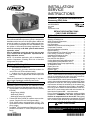
INSTALLATION/
SERVICE
INSTRUCTIONS
E2006 Lennox Industries Inc.
Dallas, Texas, USA
Humiditrol® Enhanced Dehumidification
Accessory (EDA) Units
ACCESSORIES
505,021M
02/06
Supersedes 01/06
RETAIN THESE INSTRUCTIONS
FOR FUTURE REFERENCE
Humiditrol® EDA Series Unit
Signaturet
Table of Contents
Humiditrol®
The Dave Lennox
Collection
Enhanced Dehumidification Accessory (EDA) is designed for
installation with a Lennox R−410A split−system outdoor unit
and an air handler or a furnace with a variable speed blower. This accessory is designed for indoor installations in either upflow or horizontal air discharge applications. This
unit is for use only on R−410A systems with thermal
expansion valves.
Prior to installation, study the decision tree on page
16 to confirm that all application requirements for
EDA installation are met.
NOTE − For downflow application, refer to Installation Instruction Supplement, Installing EDA Unit in Downflow
Configuration 505,134M.
Shipping & Packing List
S
S
1 − Assembled EDA indoor unit
1 − Bag assembly (includes check/flow restrictor for
use on EDA coil, EDA notification label).
S 1 − Outdoor fan relay and wiring harness (used only
with outdoor units equipped with variable speed fan
motors)
Check the components for shipping damage. If any damage is found, immediately contact the last carrier.
Other Required Components
Separately-ordered components are restricted to those
listed in the Engineering Handbook and the price book:
S SignatureStatt thermostat [Outdoor Sensor (46M98)
included],
− Single-stage (81M26)
− Multi−stage (81M27)
− Multi−stage heat-pump (81M28)
S Twisted Pair Wire (84X49) for outdoor sensor to thermostat − Required for use with SignatureStatt.
S 75VA 24VAC indoor unit transformer (12P61) − Required when EDA unit is installed with a two-stage heat
pump system.
S Humiditrol® EDA Insulation and Piping Kit (refer to applications information in Lennox Engineering Handbook)
02/06
*2P0206*
Litho U.S.A.
EDA Series Unit . . . . . . . . . . . . . . . . . . . . . . . . . . . . . . .
Shipping & Packing List . . . . . . . . . . . . . . . . . . . . . . . .
Other Required Components . . . . . . . . . . . . . . . . . . . .
General Information . . . . . . . . . . . . . . . . . . . . . . . . . . .
Unit Dimensions . . . . . . . . . . . . . . . . . . . . . . . . . . . . . . .
Installation Dimensions and Arrangement . . . . . . . . .
Component Functions . . . . . . . . . . . . . . . . . . . . . . . . . .
General Installation Information . . . . . . . . . . . . . . . . .
Electrical Wiring . . . . . . . . . . . . . . . . . . . . . . . . . . . . . . .
EDA Installation Flow Chart & Procedures . . . . . . . .
Leak Testing, Evacuation, Charging . . . . . . . . . . . . . .
Insulating and Sealing the Unit . . . . . . . . . . . . . . . . . .
Other System Components . . . . . . . . . . . . . . . . . . . . .
How the EDA Unit Works . . . . . . . . . . . . . . . . . . . . . . .
Cooling Mode with Dehumidification ON . . . . . . . . . .
Cooling Mode (Dehumidification OFF) . . . . . . . . . . . .
Heating Mode (Heat Pump Applications) . . . . . . . . . .
Air Resistance Table . . . . . . . . . . . . . . . . . . . . . . . . . . .
Repair Parts List . . . . . . . . . . . . . . . . . . . . . . . . . . . . . .
Wiring Diagrams . . . . . . . . . . . . . . . . . . . . . . . . . . . . . .
Decision Tree . . . . . . . . . . . . . . . . . . . . . . . . . . . . . . . . .
1
1
1
1
2
3
4
5
5
5
8
9
9
10
10
11
11
13
13
13
16
General Information
NOTE − These instructions are intended as a general guide
and do not supersede local codes in any way. Consult authorities having jurisdiction before installation.
The Humiditrol® EDA unit will operate to dehumidify, as required, when ambient temperatures are below 95ºF. When
temperatures reach 95ºF, the cooling and dehumidification
requirements will both be satisfied by the increased system runtime. In applications that include a Humiditrol®
EDA unit, a call to activate the dehumidification mode at or
above 95ºF is unnecessary and would not be issued or allowed by the SignatureStatt room thermostat.
Prior to system checkout, consider the outdoor ambient
temperature. REMEMBER, the EDA unit does NOT
function in temperatures at or above 95ºF. Plan testing
to be conducted when temperatures are between 65ºF and
95ºF to ensure proper EDA set up and checkout operation.
IMPORTANT
The approved application for the EDA Series unit is
restricted to those listed in the Engineering Handbook and price book.
505,021M
*P505021M*
WARNING
WARNING
This cased product contains fiberglass wool. Disturbing the insulation during installation, maintenance, or repair will expose you to fiberglass wool
dust. Breathing this may cause lung cancer. (Fiberglass wool is known to the State of California to
cause cancer.)
Fiberglass wool may also cause respiratory, skin,
and eye irritation.
Risk of explosion or fire. Can cause
injury or death. Recover all refrigerant
to relieve pressure before opening the
system.
To reduce exposure to this substance or for further
information, consult material safety data sheets
available from address shown below, or contact
your supervisor.
IMPORTANT
The Clean Air Act of 1990 bans the intentional venting of refrigerant (CFC’s, HFC’s, and HCFC’s) as of
July 1, 1992. Approved methods of recovery, recycling or reclaiming must be followed. Fines and/or incarceration may be levied for noncompliance.
Lennox Industries Inc.
P.O. Box 799900
Dallas, TX 75379−9900
Unit Dimensions
EDA Model Dimensions − Inches (mm)
Dimension
EDA−024B
EDA−036C
EDA−060D
A
17−1/2 (445)
21 (533)
24−1/2 (622)
B
12−1/4 (311)
12−1/4 (311)
14 (356)
C
16−1/8 (422)
19−5/8 (498)
23−1/8 (587)
D
16−1/8 (422)
19-5/8 (498)
23−1/8 (587)
E
1−3/8 (35)
3−1/8 (79)
4−7/8 (124)
F
3−1/8 (79)
4−7/8 (124)
6−5/8 (168)
G
3 (76)
3−1/4 (83)
4−3/4 (121)
Check/Flow Restrictor
to Vapor Line Tee
11/16 (17)
D
11/16
(17)
20−3/4
(527)
To Charge Compensator
side connection
Electrical
Inlet
22−1/4
(565)
Liquid Line to
Indoor TXV
G
E
1
(25)
9−1/2
(241)
F
B
2−1/2
(64)
1−3/4
(44)
INLET AIR OPENING
INLET AIR OPENING
C
11/16 (17)
EDA 01/06
11/16
(17)
11/16 (17)
A
Liquid Line
From Outdoor
Unit
OUTLET
AIR
OPENING
11/16 (17)
1−7/16 (37)
Page 2
20−1/8
(511)
11/16 (17)
Installation Dimensions and Arrangement
EDA−024B: 12−1/2
EDA−036C: 12−1/2
EDA−060D: 14
EDA UNIT
(TRANSITION
See Note 2)
12" (min.)
Varies by indoor
coil model; see
LENNOX
Engineering
Handbook.
INDOOR
COIL
Varies by air
handler model; see
LENNOX
Engineering
Handbook for
dimensions.
FURNACE
TYPICAL
UP−FLOW
POSITION
(Furnace Shown)
TRANSITION
(See Note 1)
AIR FLOW
40
AIR FLOW
UP-FLOW AIR
HANDLER
UP-FLOW FURNACE
NOTES:
1. Transition is required for all air handlers; dimension
width and depth is dependent upon the air handler
and the EDA model used.
2. Transition is required between indoor coil and EDA
if 5 ton EDA unit is used with small profile furnace.
TYPICAL HORIZONTAL
POSITION (Furnace Shown)
Figure 1
Page 3
EDA INSTALLATION/ SERVICE INSTRUCTIONS
Check/Flow Restrictor Operation
Component Functions
Charge CompensatorThe charge compensator
(shown in figure 5) serves to maintain the proper amount of
refrigerant circulating in larger systems. [Some systems
do not require a charge compensator, but do require a similar kit to connect into the system (see Engineering Handbook)]
FROM
VAPOR
LINE
TEE
FROM
VAPOR
LINE
TEE
The charge compensator stores excess refrigerant when
the EDA coil is active and returns it to the system during
normal cooling or heating operations. When the EDA coil is
active, less charge is required to obtain the proper amount
of subcooling because of the additional coil surface and
the cooler air which passes over the EDA coil.
CHECK/FLOW
RESTRICTOR FLOATS IN
CHATLEFF CONNECTOR
GREATER
PRESSURE
O−RING SEALS
CHECK/FLOW
RESTRICTOR
GREATER
PRESSURE
EDA
UNIT
EDA
UNIT
Figure 2
Valve AssemblyThe first valve of the diverting valve assembly (figure 3, E) directs the flow of refrigerant to either
bypass the EDA coil (EDA coil is inactive) or pass through
the EDA coil (EDA coil is active).The second valve (figure 3
F) directs the flow of refrigerant back to the liquid line when
the first valve (E) allows flow through the EDA coil. When
the EDA coil is inactive, the second valve (F) provides a
vent path to the suction line, draining the EDA coil and
charge compensator of liquid refrigerant.
Check/Flow RestrictorThe check function of the
check/flow restrictor (shown in figure 2) prevents refrigerant from flowing into the inactive components during times
when the EDA coil is inactive. The flow restrictor controls
the rate of return of charge to the system from the charge
compensator and the EDA coil when the system changes
from "EDA coil active" to "EDA coil inactive."
EDA Unit Parts Arrangement
A
B
EDA−024B
C
D
A
B
EDA−036C
C
D
A
B
EDA−060D
C
EDA COIL
EDA COIL
E
F
E
F
E
F
3−WAY DIVERTING VALVE ASSEMBLY 3−WAY DIVERTING VALVE ASSEMBLY
3−WAY DIVERTING VALVE ASSEMBLY
A − Liquid Line From Outdoor Unit
B − Liquid Line to Indoor TXV
C − Check/Flow Restrictor to Vapor
Line Tee
EDA COIL
D − To Charge Compensator side connection (1/4" line must be brazed closed on systems that do not
require the installation of a charge compensator)
E − EDA inactive mode − bypasses the EDA EDA active mode − allows refrigerant flow through EDA
F − EDA inactive mode − vent path to suction line; EDA active mode − directs refrigerant flow back to
liquid line
Figure 3
EDA 01/06
D
Page 4
Releasing Air Charge
General Installation Information
NOTE − EDA units use dry air as a holding charge.
WARNING
CAUTION
Improper installation, adjustment, alteration, service or maintenance can cause personal injury, loss
of life, or damage to property.
Installation and service must be performed by a
qualified installer or service agency.
The EDA coil is shipped from the factory pressurized with dry air. Pierce a hole in the coil’s rubber
plug vapor line seal to relieve the pressure before removing the seals.
The EDA unit may be used in upflow or horizontal discharge installations. Slots around the inlet end of the EDA
cabinet are provided to secure the EDA unit to the duct
flanges of indoor coil/air handler cabinets. Use field-provided #8 x 1" long SDST screw (usually 6 required).
Ensure that the coil is void of pressure. Remove the rubber
plug from the lines.
NOTE − If there is no pressure when the plugs are pierced,
check the unit for leaks before continuing with the installation.
Refrigerant Line Connections
NOTE − When connecting lines, be careful to avoid damaging the 3−way diverting valve access panel. Place a wet rag
against the piping plate and around the EDA unit line connections. A wet rag heat shield must be in place during
brazing to guard against damage to the paint.
CAUTION
Physical contact with metal edges and corners
while applying excessive force or rapid motion can
result in personal injury. Be aware of, and use
caution when working nearby these areas during
installation or while servicing this equipment.
Electrical Wiring
Refrigeration
All EDA coils are shipped with a combination check/flow
restrictor. The restrictor is provided in the bag assembly and must be installed. Refer to the appropriate high
and/or low side installation instructions for information on
the appropriate line sets. Refer to Lennox Refrigerant Piping guide (Corp. 9351−L9) for proper size, type, and application of field−fabricated lines.
Electrical wiring diagrams are provided in figures 12 and 13
(see pages 14 and 15). Some modifications to certain units
may be necessary. Review the diagrams before installation to ensure all necessary components are on hand at
time of installation.
EDA Installation and Checkout Flow Chart
Follow the procedures in the flow chart in figure 4 while referring to the illustration in figure 5 to install the EDA: and
associated components.
Page 5
EDA INSTALLATION/ SERVICE INSTRUCTIONS
EDA Installation & Checkout Flow Chart
Required Parts (all applications)
start
ARE
ALL REQUIRED
PARTS
AVAILABLE
?
EDA Unit, with check/flow restrictor & label
Appropriate SignatureStatt Thermostat
46M98 − Outdoor Sensor
84X49 − Twisted Pair Wire
Appropriate Insulation and Piping Kit
NO
PROCURE
MISSING PARTS
Required Parts (2−Stage Heat Pump appl.)
12P61 − 75VA Transformer (for HP applications)
YES
Installation Process
ENSURE ALL POWER IS OFF
Check Dehumidification Operation
MAKE WIRING CONNECTIONS
AS SHOWN IN FIGURES 12 & 13
(SEE PAGES 14 AND 15)
INSTALL EDA UNIT IN DUCT
SYSTEM
INSTALL EDA" LABEL ON
OUTDOOR UNIT
INSTALL THE CHARGE
COMPENSATOR (IF REQUIRED)
IN CONVENIENT LOCATION
(SEE FIGURE 5)
MAKE ALL REFRIGERATION
CONNECTIONS, BEING SURE
TO INSTALL THE CHECK/FLOW
RESTRICTOR (SEE FIGURE 5)
LEAK CHECK THE SYSTEM
WITH 3−WAY VALVE ASSEMBLY
SET TO EVACUATE" (SEE
FIGURE 7)
POWER UP THE INDOOR UNIT
CHECK THAT 3−WAY VALVE
ASSEMBLY IS SET TO
COOLING" POSITION AS
SHOWN IN FIGURE 7
ENABLE HUMIDITROL ON
ROOM THERMOSTAT (SEE
FIGURE 8)
SET THERMOSTAT FOR
MAXIMUM COOLING
INSULATE ALL REFRIGERANT
LINES
OPEN REFRIGERANT VALVES
EVACUATE THE SYSTEM AS
DESCRIBED IN THE OUTDOOR
UNIT INSTALLATION
INSTRUCTIONS
INSTALL OUTDOOR SENSOR
TURN OUTDOOR UNIT MAIN
POWER ON
CHECK CHARGE AND CHARGE
AS NEEDED (SEE PAGE 8)
Figure 4
EDA 01/06
Page 6
SET COOLING SETPOINT ON ROOM THERMOSTAT
TO 2 DEGREES ABOVE INDOOR TEMPERATURE
(OUTDOOR UNIT WILL TURN OFF)
NOTE − A Humiditrol® EDA−equipped system is allowed
to operate and cool room temperature below set point
(but only by 2ºF) when trying to satisfy a persisting humidity set point.
SET DEHUMIDIFICATION SETPOINT TO 5% BELOW
CURRENT ROOM RELATIVE HUMIDITY
IS
THE
OUTDOOR
TEMPERATURE
BELOW
95ºF
?
YES
NO
DEHUMIDIFICATION
IS DE−ACTIVATED;
CHECK FOR
CORRECT
OPERATION AT A
TIME WHEN
AMBIENT
TEMPERATURE IS
BELOW 95ºF.
OUTDOOR UNIT:
COMPRESSOR IN HIGH STAGE;
FAN IN LOWEST SPEED;
EDA:
3−WAY VALVE ASSEMBLY TO DEHUMIDIFICATION"
POSITION
INDOOR UNIT:
FAN IN DEHUMIDIFICATION SPEED
CHECK THE TEMPERATURE DIFFERENCE
ACROSS THE EDA COIL AND THE LIQUID LINE
TEMPERATURES AS NOTED IN FIGURE 9 ON
PAGE 10
Typical Installation (Horizontal Air Handler shown)
EDA UNIT
Check/FlowRestrictor
Details
Electrical Inlet
To Charge
Compensator side
connection (some
applications)
Check/Flow
Restrictor to Vapor
Line Tee
TEFLON SEAL
CHECK/FLOW
RESTRICTOR
AND O−RING
FITTING IN
EDA UNIT
AIR
FLOW
IMPORTANT!
RESTRICTOR MUST BE INSERTED WITH O−RING
END OF RESTRICTOR TOWARD EDA UNIT FITTING.
TORQUE CHATLEFF CONNECTION TO 20 FT. LBS.
Liquid Line to
Indoor TXV
MUST BE INSULATED
Liquid Line From
Outdoor Unit
TXV Liquid
Line
System without
compensator
INDOOR
UNIT
1/4" PORT MUST
BE BRAZED
CLOSED
air−flow
Vapor
Line
EDA
NO CHARGE
COMPENSATOR
OR 1/4" LINE
OUTDOOR
UNIT
Liquid Line from
Outdoor Unit
Liquid Line to
Indoor TXV
Vapor
Line
MUST BE
INSULATED
ELECTRICAL
INLET
Liquid
Line
TO CHARGE
COMPENSATOR SIDE
CONNECTION
Charge
Compensator
Details
CHECK/FLOW
RESTRICTOR TO
VAPOR LINE TEE
LIQUID LINE
TO INDOOR
TXV
2 ft. max.
USE REDUCER(S) FROM
CHARGE COMPENSATOR KIT
(WHEN REQUIRED)
VAPOR LINE FROM
INDOOR COIL
DROP TO CHARGE
COMPENSATOR
VAPOR LINE
FROM
OUTDOOR
UNIT
LIQUID LINE FROM
OUTDOOR UNIT
7/8 X 7/8 X
3/8 TEE
CHARGE
COMPENSATOR
6 ft. max.
BETWEEN CHARGE
COMPENSATOR AND EDA USING
1/4" LINE PROVIDED IN CHARGE
COMPENSATOR KIT
TO CHECK/FLOW
RESTRICTOR ON EDA
USE REDUCER(S)
FROM CHARGE
COMPENSATOR KIT
(WHEN REQUIRED)
1/4" TUBING
CONNECTION − MUST
BE AT LOWEST POINT
OF THE COMPENSATOR
TYPICAL HORIZONTAL POSITION INSTALLATION
VAPOR
LINE
FROM
INDOOR
COIL
CHARGE
COMPENSATOR
1/4" TUBING
CONNECTION −
MUST BE ON
BOTTOM OF
COMPENSATOR
USE REDUCER(S)
FROM CHARGE
COMPENSATOR KIT
(WHEN REQUIRED)
TO CHECK/FLOW
RESTRICTOR ON EDA
7/8 X 7/8 X
3/8 TEE
VAPOR LINE FROM
OUTDOOR UNIT
UPFLOW POSITION
Figure 5
Page 7
EDA INSTALLATION/ SERVICE INSTRUCTIONS
Leak Testing, Evacuating, Charging
IMPORTANT
Prior to starting the outdoor unit for charging, be
sure the 3-way valve is energized and in the cooling" (forward) position (see figure 7).
IMPORTANT
The 3−way diverting valve actuator shaft setscrew
(see figure 7) is factory set and is not to be adjusted.
3−way Diverting Valve Operation
NOTE − During system operation, the 3-way valve requires
24-volt power to drive between cooling and dehumidification.
The 3−way diverting valve is actually two valves connected
by a common shaft, designed to open one valve while closing the other, and vice versa. For evacuating (with power
off), the diverting valve can be REPOSITIONED using its
actuator lever, a long setscrew that has been factory-set to
a precise point on the common shaft. Do not loosen (unscrew) the setscrew. Should the setscrew become
loose, carefully follow the note in figure 6 to position
and tighten it.
Re−aligning Setscrew
NOTE − Actuator shaft setscrew is factory set and must not be adjusted. If the set screw should become loose, use a pliers to grip the
shaft where shown (1) and rotate the shaft (in direction of the black
arrow) until the pin stops (inset shows pin and stops). Press the red
button (2) in the direction of the white arrow and move the lever (3)
to the forward position and tighten setscrew to 60 in-lbs torque.
3. Very little charge is required for the additional volume
of the EDA unit. When in normal cooling, the components will all be occupied by vapor that has very little
weight. At most (depending on the model) an additional 1/4 pound of refrigerant may be required.
4. When shifting from dehumidify mode to cooling, or
vice versa, wait at least 10 minutes for the system to
reach stable operating pressure before checking temperatures and pressures, or adjusting refrigerant
charge.
NOTE − Prior to starting the outdoor unit for charging,
set the thermostat to call for cooling (dehumidification
OFF). It will take about 90 seconds for the 3−way diverting valve to energize and shift to the cooling position. To ensure that the 3-way diverting valve is energized and in the cooling" (forward) position, observe
the position of the 3-way diverting valve actuator shaft
setscrew in figure 7; if properly shifted, the setscrew
will be in the forward position.
Setting 3−Way Diverting Valve to
Evacuate Position
1. PUSH RED TAB IN DIRECTION INDICATED.
2. PUSH ACTUATOR SHAFT DOWN TOWARD THE
CENTER−OF−TRAVEL POSITION
2
1
1
3
2
STOP
PIN
SHAFT
STOP
COOLING
(FORWARD)
Figure 6
EVACUATE
(CENTER)
Leak Testing, Evacuating, Charging
1. Set the 3−way diverting valve actuator shaft to the center (evacuate) position for leak testing and evacuation
(see figure 7). IMPORTANT! The actuator shaft
must be set as described to allow the EDA to evacuate more quickly.
2. Refer to instructions provided with the outdoor unit for
leak testing, evacuating and charging procedures.
EDA 01/06
Page 8
DEHUMIDIFICATION
(REARWARD)
Figure 7
5. The charge must be checked with the system in cooling operation (dehumidification OFF). After testing
and charging as required, set the thermostat to force
a demand for dehumidification.
Then, select HUMIDITROL mode from the DEHUMIDIFY
menu (follow the path: MENU −> DEHUMIDIFY). The user
control sequence is also shown in figure 8, C through H;
specifically:
Insulating and Sealing the Unit
IMPORTANT
S
S
All piping, metering devices, and connections must
be insulated to prevent moisture damage caused by
sweating.
Seal the unit so that warm air is not allowed into the cabinet. This is especially important when the unit is installed in
an unconditioned area. Make sure the liquid line entry
points are sealed with either refrigerant tube insulating material or with Permagum (see figure 5 on page 7).
Turn on Humiditrol − D & E
Set level of dehumidification − F through H (adjustment
range is from 45% to 60% and is factory set to 50%)
If HUMIDITROL is enabled and the outdoor sensor is disconnected, operation is NOT allowed in dehumidification
mode. This is indicated by the display of "OUTSIDE ERR"
on the SignatureStatt thermostat Home screen.
Setting Thermostat
Other System Components
Installer Setup
Blower Control
EDA units are to be applied with an indoor unit that has a
variable speed motor (VSM). Refer to the indoor unit installation instruction for setting blower speed.
INSTALLER SETTINGS Y
AUTO CHANGEOVER
ON
EER
ON
DEADBAND
4.0°F
HUMIDITROL
OFF
MAIN MENU
Thermostat and Sensor
A
IMPORTANT
HOME
DISABLE
ENABLE
INSTALL MENU
User Controls
MAIN MENU
PROGRAM
HEAT / COOL
HUMIDIFY
DEHUMIDIFY
A SignatureStatt thermostat and properlyconnected outdoor sensor is REQUIRED for the
EDA unit to function properly. Twisted pair wire
(84X49 or equivalent) is REQUIRED between the
SignatureStat and the outdoor sensor.
B
SELECT
HUMIDITROL
↓
SELECT
DEHUMIDIFY MENU
MODE
OFF
DEHUMIDIFY
50%
MAIN MENU
C
Install the remote sensor on the outside of a northern wall
of the home, away from direct sunlight or other heat
sources that may affect its sensitivity.
Refer to the SignatureStatt thermostat Installation
Instructions for installation, wiring, and setup. Also refer to
the SignatureStatt Thermostat Programming Guide for
programming and settings.
To configure the thermostat for operation with a Humiditrol® system, first enable HUMIDITROL in the thermostat’s
installer settings (follow the path: MENU −> INSTALLER
SETTINGS −> HUMIDITROL − see figure 8, A and B).
Page 9
DEHUMIDIFY MENU
MODE
HUMIDITROL
DEHUMIDIFY
50%
SELECT
MAIN MENU
E
DEHUM MENU
SELECT
SELECT
F
DEHUMIDIFY
CONTROL
50 %
SELECT
D
DEHUMIDIFY MODE
OFF
HUMIDITROL
DEHUM MENU
SELECT
B
↑
↓
DEHUMIDIFY MENU
MODE
HUMIDITROL
DEHUMIDIFY
55%
MAIN MENU
G
SELECT
H
Figure 8
EDA INSTALLATION/ SERVICE INSTRUCTIONS
EDA Unit Operation
Cooling Mode (Dehumidification ON)
The EDA coil is added to an HVAC system downstream of
the indoor coil. In dehumidification mode, the coil becomes
an extension of the condenser coil and injects heat into the
indoor air stream.
This dehumidification mode allows significantly improved
control of the humidity in the conditioned space without
overcooling the space. The assembly includes a set of
3−way diverting valves which will either route refrigerant
through the EDA coil, or cause the refrigerant to bypass
the EDA coil, depending on the mode of operation.
Operation Notes
1. IMPORTANT REMINDER! Dehumidification will not
occur when the outside temperature is at or above
95ºF.
2. When operating in cooling (or heat pump heating)
mode, all temperatures and pressures will be as in a
normal system.
3. When the thermostat is in HUMIDITROL mode, and
after a cooling demand has been satisfied but a dehumidification demand persists and the room temperature is not more than 2°F below the setpoint, the air
handlers will operate at reduced airflow with the compressor at high speed.
4. When the unit is in the dehumidification
mode, the display will show a raindrop"
icon with an imbedded negative sign and
the current relative humidity to its right.
If the room thermostat’s cooling demand has been satisfied but the dehumidification setting has not been satisfied,
the unit continues to run in dehumidification mode. The
room thermostat sends a signal to the EDA unit’s 3−way diverting valve assembly to begin operating in the dehumidification mode.
Figure 9 shows refrigerant flowing from the outdoor unit,
entering the EDA, passing through the first 3−way diverting
valve, then entering the EDA coil. There, heat from the
warm refrigerant is transferred into the indoor air stream.
The refrigerant exits the coil through the second 3−way diverting valve and into the indoor coil expansion valve.
During dehumidification, the indoor air blower (and outdoor
fan, if an outdoor relay is used) operates at a lower air volume. The cool, dehumidified air leaving the indoor coil is
warmed as it passes over the EDA coil. Air temperature
rise across the EDA coil can be from 10° to 25°F, depending on the operating ambient and air-conditioned space
conditions.
The warm vapor−liquid−refrigerant mixture entering the
EDA unit from the outdoor unit will be subcooled in the EDA
unit and enter the expansion valve at a lower-than-normal
temperature. Liquid temperatures can be in the 65° to 70°F
range, with a 10° to 40°F temperature change across the
EDA.
Cooling Cycle with EDA Coil Active (Model EDA−036C shown)
VAPOR
LINE VALVE
7/8 x 7/8 x
3/8 TEE
CHARGE COMPENSATOR
(holding some refrigerant)
See note 3.
OUTDOOR UNIT
See note 1
See note 1
CHECK/FLOW
RESTRICTOR
(flow permitted)
See note 2
See note 2
CHECK/
EXPANSION
VALVE
LIQUID
LINE
VALVE
air flow
INDOOR COIL
3−WAY
DIVERTING
VALVE
INDOOR
BLOWER
INDOOR
UNIT
NOTE 1. With EDA Coil Active, expect a 10 to 25ºF air temperature rise across EDA coils.
NOTE 2. With EDA Coil Active, expect a 10 to 40ºF liquid line temperature change across EDA coils.
NOTE 3. Charge compensator and 1/4" line not required on all systems. See Engineering Handbook.
Figure 9
EDA 01/06
Page 10
Cooling Mode (Dehumidification OFF)
Figure 10 illustrates refrigerant flow in cooling mode (dehumidification mode OFF),
The liquid refrigerant from the outdoor unit enters the EDA
module . Since there is no demand for dehumidification,
the 3−way diverting valve assembly directs the flow back
out of the EDA module to the indoor unit expansion valve.
Cooling Cycle with EDA Coil Inactive (Model EDA−036C shown)
VAPOR
LINE VALVE
CHARGE COMPENSATOR
(NOT holding refrigerant)
See note 3.
7/8 x 7/8 x
3/8 TEE
See note 1
See note 1
CHECK/FLOW
RESTRICTOR
(flow restricted)
See note 2
See note 2
INDOOR
BLOWER
CHECK/
EXPANSION
VALVE
LIQUID
LINE
VALVE
OUTDOOR UNIT
air flow
INDOOR COIL
3−WAY
DIVERTING
VALVE
NOTE 1. In Cooling Mode, no air temperature change across EDA coils.
INDOOR UNIT
NOTE 2. In Cooling Mode, no liquid line temperature change across EDA coils.
NOTE 3. Charge compensator and 1/4" line not required on all systems. See Engineering Handbook.
Figure 10
Heating Mode (Heat Pump Applications)
Figure 11 illustrates refrigerant flow in the heating mode.
In heat pump application heating mode, a system that includes an EDA unit will operate as a conventional heat
pump. The EDA unit does not operate in this mode.
Heat Pump Heating Cycle with EDA Coil Inactive (Model EDA−036C shown)
OUTDOOR UNIT
CHARGE COMPENSATOR
See note 3.
7/8 x 7/8 x
3/8 TEE
See note 1
See note 1
CHECK/FLOW
RESTRICTOR
(flow restricted)
See note 2
See note 2
air flow
INDOOR COIL
VAPOR
LINE VALVE
INDOOR
BLOWER
CHECK/
EXPANSION
VALVE
LIQUID
LINE
VALVE
INDOOR UNIT
NOTE 1. In Heating Mode, no air temperature change across EDA coils.
NOTE 2. In Heating Mode, no liquid line temperature change across EDA coils.
NOTE 3. Charge compensator and 1/4" line not required on all systems. See Engineering Handbook.
Figure 11
Page 11
EDA INSTALLATION/ SERVICE INSTRUCTIONS
Check List
n
Checkpoint
What to Check
Action
Thermostat and
Sensor
Wiring
Confirm Sensor connected to SignatureStatt using twisted pair
wire (see wiring diagram figure 13)
Thermostat
Humiditrol® Installer Settings
Confirm HUMIDITROL is enabled (see figure 8)
Thermostat
Humiditrol® User Settings
Confirm HUMIDITROL − Dehumidify − ON is selected (see figure 8)
Thermostat
Humiditrol® User Settings
Confirm Relative Humidity setting (see figure 8)
Indoor Unit
Variable-Speed Blower Settings
Confirm Settings for D": CFM = 60% to 65% of 2nd-stage cool
(see indoor unit installation instructions and table 1, below)
Insulation
Charge Compensator
Insulation
Liquid Line
Insulation
Vent Line to Suction Line
Charge Compensator
1/4"Line
Confirm 1/4" port oriented downward (see charge compensator
details, figure 5)
Check/Flow Restrictor
3/8" Line
Confirm restrictor installed/oriented properly (see check/flow restrictor details figure 5)
System Charge
Refrigerant
With unit running in cooling mode, check and confirm system is
properly charged (see outdoor unit installation instructions).
Outdoor Unit
Fan Relay
Confirm (if unit has variable speed outdoor fan) relay is installed
properly (see wiring diagram figures 12 and 13)
Outdoor Unit
EDA Label
Confirm label is installed in prominent location and will be easily
visible during servicing.
Confirm
C
fi iinsulation
l ti iis properly
l iinstalled
t ll d ((see charge
h
compensator
t kit
instructions; also, see figure 5)
NOTE − System will NOT operate in dehumidification mode with outdoor temperature at or above 95ºF.
Operational Status
Dehumidification Mode
Record supply air temperature and confirm temperature that it is
higher than in cooling mode.
Operational Status
Dehumidification Mode
On units with variable speed outdoor fan, check that fan operates
at approximately 250 rpm (lowest speed).
Table 1
Demand Signals − Humiditrol® EDA Enabled
Operating Sequence
System Demand
System Response
Thermostat Demand
System Type
Step
Y1
Y2
Relative Humidity
Blower
CFM
(Cool) %
G
Status
D
ComCom
pressor
ON
ON
ON
ON
ON
ON
Acceptable
Acceptable
Acceptable
24 VAC
24 VAC
24 VAC
High
Low
High
100
70
100
Compressor
p
and indoor
blower follow
bl
f ll
thermostat
th
t t
demand
ON
ON
ON
ON
ON
ON
Demand
Demand
Demand
24 VAC
24 VAC
24 VAC
High
Low
High
100
70
100
Cooling
g operation
p
has
priority
i it
A Humiditrol® EDA−
equipped system is allowed
to operate and cool room
temperature below set point
(but only by 2
2ºF)
F) when try
trying to satisfy a persisting
humidity set point; it is not
allowed to operate at all
when outdoor temperature
is >95ºF.
O
Comments
Cooling Operation − No call for dehumidification
Single-stage outdoor unit
Two-stage outdoor unit Y1
Two-stage outdoor unit Y2
1
1
2
ON
ON
ON
(na)
−
ON
Demand for Dehumidification and Cooling
Single-stage outdoor unit
Two-stage outdoor unit Y1
Two-stage outdoor unit Y2
1
1
2
ON
ON
ON
(na)
−
ON
Dehumidification Mode Only − No Cooling Demand
Single-stage outdoor unit
1
ON
(na)
ON
ON
Demand
0 VAC
High
50 − 70*
Two-stage outdoor unit Y2
2
ON
ON
ON
ON
Demand
0 VAC
High
50 − 70*
* NOTE − Blower CFM speed (percentage) will vary depending on selected indoor equipment (furnace, coil blower, etc.).
EDA 01/06
Page 12
Air Resistance
Repair Parts
Table 2 shows air volume and total air resistance for the
available EDA models.
Table 2
Air Resistance
Model No.
EDA−024B
EDA−036C
EDA−060DB
S
S
S
S
S
3−way diverting valve assembly
Check/flow restrictor
EDA Relay
Outdoor unit relay
Teflon seals
Wiring Diagrams
Air Volume
cfm
L/s
Total Air Resistance
in. w.g.
Pa
400
190
0.05
12
600
285
0.10
25
800
380
0.15
37
1000
470
0.22
55
Typical condensing unit and heat pump wiring diagrams
are provided in figures 12 and 13. Some modifications to
certain units may be necessary.
Connect the EDA unit with the indoor and outdoor units,
and to the thermostat. Be sure the outdoor sensor is
installed and connected to the SignatureStatt thermostat’s outdoor sensor terminal block. Table 3 shows the requirements for control wiring.
600
285
0.05
12
Table 3
800
380
0.08
20
Control Wiring Requirements
1000
470
0.11
27
1200
565
0.15
37
1400
660
0.20
50
1000
470
0.05
12
1200
565
0.06
15
1400
660
0.08
20
1600
755
0.10
25
1800
850
0.11
27
2000
945
0.13
32
2200
1040
0.15
37
Units:
System
type
2 stage
AC
1 stage
AC
2 stage
HP
1 stage
HP
(all)
SignatureStatt to
Sensor
2
(twisted
pair)
(with LSOM)
(without LSOM)
Indoor unit to:
Humiditrol®
EDA
SignatureStatt
Outdoor
unit
SignatureStatt
Outdoor
unit
9*
6
8*
4
8*
5
7*
3
10*
8
9*
7
9*
7
8*
6
3
*Includes conductor for 2−stage heat
Page 13
EDA INSTALLATION/ SERVICE INSTRUCTIONS
Typical EDA/Condensing Unit Wiring Diagram
Red
Black
Black
*OUTDOOR RELAY NOT REQUIRED WITH SINGLESPEED OUTDOOR FAN
5
2nd, rewire yellow
wire as shown
Violet
Purple
7
1
VALVE
ACTUATOR
Orange
Black
RED
K1
Yellow
BLACK
PURPLE
Purple
BLACK
Yellow
Blue
B4
FAN
3
EDA
Yellow
1st, cut yellow
wire here.
5
2
Use Wirenuts
SEE CONTROL WIRING BELOW
FOR THERMOSTAT WIRING
RED
YELLOW
DSY1 JUMPER − MUST BE
REMOVED FOR HUMIDITROL
OPERATION
BLUE
BLACK
BROWN
INDOOR
UNIT
Y1Y2 JUMPER − ONLY
REMOVE IF 2−STAGE COOLING
OUTDOOR WIRING
(VSM APPLICATION
ONLY)
OUTDOOR
UNIT
INDOOR
UNIT
RED (NOT REQUIRED FOR
APPLICATIONS WITHOUT LSOM)
SignatureStatt
THERMOSTAT
OUTDOOR
SENSOR
(46M98)
TWISTED PAIR
RED
PURPLE
EDA
UNIT
BLACK
PURPLE
BLACK
FAN RELAY (NOT REQUIRED
WITH SINGLE-SPEED
OUTDOOR FAN)
YELLOW
BLUE (NOT REQUIRED FOR SINGLE STAGE)
BLACK
BROWN (NOT REQUIRED FOR
APPLICATIONS WITHOUT LSOM)
Control Wiring
Figure 12
EDA 01/06
Page 14
Y1Y2 JUMPER − IN FOR
SINGLE− STAGE COOLING;
REMOVED FOR 2−STAGE
COOLING
Typical EDA/Heat Pump Wiring Diagram
Black
Black
*OUTDOOR RELAY NOT REQUIRED WITH SINGLESPEED OUTDOOR FAN
5
2nd, rewire
yellow wire
as shown
Purple
7
1
VALVE
ACTUATOR
Orange
Black
RED
K1
Yellow
BLACK
PURPLE
Purple
BLACK
Yellow
Blue
B4
FAN
Violet
EDA
Yellow
1st, cut
yellow wire
here.
3
5
2
Use Wirenuts
INDOOR
UNIT
OUTDOOR
WIRING
(VSM
APPLICATION
ONLY)
DSY1 JUMPER − MUST BE
REMOVED FOR HUMIDITROL
OPERATION
BLUE
BROWN
SEE CONTROL WIRING BELOW
FOR THERMOSTAT
WONNECTIONS
RO JUMPER − MUST BE
REMOVED FOR HEAT PUMP
APPLICATION
BLUE
OUTDOOR
UNIT
INDOOR
UNIT
RED
FAN RELAY (NOT REQUIRED
WITH SINGLE-SPEED
OUTDOOR FAN)
PURPLE
RED
BLACK
EDA
UNIT
Y1Y2 JUMPER − ONLY
REMOVE IF 2−STAGE COOLING
SignatureStatt
THERMOSTAT
OUTDOOR
SENSOR
(46M98)
TWISTED PAIR
PURPLE
BLACK
YELLOW
BLUE
BROWN (NOT REQUIRED FOR APPLICATIONS WITHOUT LSOM)
BLUE (NOT REQUIRED FOR SINGLE STAGE)
Y1Y2 JUMPER − IN FOR
SINGLE− STAGE COOLING;
REMOVED FOR 2−STAGE
COOLING
Control Wiring
Figure 13
Page 15
EDA INSTALLATION/ SERVICE INSTRUCTIONS
Humiditrol® Enhanced Dehumidification Accessory (EDA)
Decision Tree
START
Is
dealer
R−410A & EDA
trained
?
NO
Obtain R−410A &
EDA training
YES
Zoning
application?
NO
Desired
equipment
NO
matchup listed in
EDA Engineering
Handbook?
YES
YES
Must use one of
these outdoor units:
XC21, XP19, XC13, XP13
ONLY!
Must use one of
these variable
speed indoor
units:
CBX32MV, CBWMV,
G60UHV, G60DFV,
G61MPV ONLY!
NOTE − Lennox warranties do
not cover damage or defect
resulting from operation with
system components (indoor unit,
outdoor unit, and refrigerant
control devices) which do not
match or meet the specifications
recommended by Lennox. This
unit intended to operate with
variable speed air handlers − see
Lennox Engineering Handbook
for approved matches.
(REFER TO EDA ENGINEERING HANDBOOK)
X = PREFERRED MATCH−UP
A = ALLOWED FOR PHYSICAL MATCH−UP TO EVAPORATOR
HUMIDITROL® EDA
CAPACITY
−024B
−036C
−060D
94M41
94M42
94M43
−018
X
A
−024
X
A
−030
X
A
−036
X
A
−042
X
−048
X
−060
X
Select Piping Kit
(REFER TO EDA ENGINEERING HANDBOOK AND
INSULATION & PIPING KIT INSTRUCTIONS 505,021M)
CAPACITY
OUTDOOR UNIT MODEL
PIPING KIT
−018
XC13
98M62
XP13
94M44
−024
XC13
98M62
XP13, XP19, XC21
94M44
−030
XC13, XP13
98M22
−036
XC13
98M22
XP13, XP19, XC21
94M44
−042
XC13
98M22
XP13
94M44
−048
XC13
98M22
XP13, XP19, XC21
94M44
−060
XC13
98M22
XP13, XP19, XC21
94M44
Upflow/horizontal
NOTE − AIR HANDLER REQUIRES
FIELD−FABRICATED TRANSITION
BETWEEN BLOWER OUTLET
AND EDA COIL.
How
installed
?
Upflow/
Horizontal Downflow
INSTALL
SYSTEM
Figure 14
EDA 01/06
MUST BE TXV ONLY
Must be valid ARI rated match (refer to outdoor unit Engineering Handbook)
Select EDA
Application
Not Approved
DO NOT
INSTALL
[If furnace]
Select indoor
coil
Page 16
Downflow
NOTE − REQUIRES ADDITIONAL
FIELD−FABRICATED SUPPORT
FRAME & TRANSITION; SEE
INSTALLATION SUPPLEMENT
505,134M