1
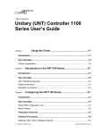
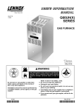
See unit nameplate for manufacturer
and address.
504,558M
8/2002
Supersedes 2/2002
GCS16−024, 030, 036, 048, 060
GCS20−024, 030, 036, 048, 060
GCS20R−024, 030, 036, 042, 048, 060
WARNING
Improper installation, adjustment, alteration, ser
vice or maintenance can cause property damage,
personal injury or loss of life. Installation and ser
vice must be performed by a qualified installer, ser
vice agency or the gas supplier
FBR113270
READ ALL INSTRUCTIONS IN THIS MANUAL
AND RETAIN FOR FUTURE REFERENCE
Litho U.S.A.
E2002
WARNING
If the information in this manual is not
followed exactly, a fire or explosion
may result causing property damage,
personal injury or loss of life.
WHAT TO DO IF YOU SMELL GAS:
Do not store or use gasoline or other
flammable vapors and liquids in the
vicinity of this or any other appliance.
Installation and service must be per
formed by a qualified installer, ser
vice agency or the gas supplier.
08/02
*2P0802*
S Do not try to light any appliance.
S Extinguish any open flames.
S Do not touch any electrical switch; do not
use any phone in your building.
S Leave the building immediately.
S Immediately call your gas supplier from a
neighbor’s phone. Follow the gas suppli
er’s instructions.
S If you cannot reach your gas supplier, call
the fire department.
504,558M
*P504558M*
GCS16, 20, and 20R Parts Arrangement
VENT CAP
COMBUSTION AIR INDUCER
GAS
VALVE
JUNCTION BOX
CONDENSER
COIL
BURNER
COMPRESSOR
Safety
1− Keep unit area clear and free of combustible materi
als, gasoline and other flammable vapors and liquids.
2− Inspect return air duct to ensure duct is sealed to
the unit and terminates outside the space contain
ing appliance.
WARNING
Product contains fiberglass wool.
Disturbing the insulation in this product during
installation, maintenance, or repair will expose you
to fiberglass wool. Breathing this may cause lung
cancer. (Fiberglass wool is known to the State of
California to cause cancer.)
Fiberglass wool may also cause respiratory, skin,
and eye irritation.
To reduce exposure to this substance or for further
information, consult material safety data sheets
available from address shown below, or contact
your supervisor.
P.O. Box 799900
Dallas, TX 75379−9900
WARNING
Do not use this furnace if any part has been under
water. A flood−damaged furnace is extremely dan
gerous. Attempts to use the furnace can result in
fire or explosion. A qualified service agency
should be contacted to inspect the furnace and to
replace all gas controls, control system parts,
electrical parts that have been wet or the furnace
if deemed necessary.
WARNING
Electric shock hazard. Can cause
injury or death. Before attempting to
perform any service or maintenance,
turn the electrical power to unit OFF at
disconnect switch(es). Unit may have
multiple power supplies.
WARNING
Danger of explosion. Can cause injury
or product or property damage. Should
the gas supply fail to shut off or if
overheating occurs, shut off the gas
valve to the furnace before shutting off
the electrical supply.
WARNING
Danger of explosion and fire. Failure to
follow safety warnings exactly could
result in dangerous operation, serious
injury, death or property damage.
CAUTION
Label all wires prior to disconnection when servic
ing controls. Wiring errors can cause improper and
dangerous operation. Verify proper operation after
servicing.
Page 1
4− Remove heat access panel.
WARNING
5− Honeywell VR8205 − Turn knob on gas valve clock
wise
until it stops. Depress knob and turn clock
wise
to OFF.
White Rodgers 36E − Turn knob on gas valve 180° ei
ther way to OFF.
Danger of electrical shock, explosion
and fire. Improper servicing could
result in dangerous operation, serious
inujry, death or property damage.
6− Wait five minutes to clear out any gas. If you then
smell gas, STOP! Immediately call your gas supplier
from your neighbor’s phone. Follow the gas supplier’s
instructions. If you don’t smell gas go to next step.
Unit Operation
FOR YOUR SAFETY READ BEFORE LIGHTING
BEFORE LIGHTING smell all around the furnace area for
gas. Be sure to smell next to the floor because some gas
is heavier than air and will settle on the floor.
Gas Valve Operation (Figure 2)
7− Honeywell VR8205 − Turn knob on gas valve counter
clockwise
until it stops. Allow knob to pop up and
continue counterclockwise to ON position.
Use only your hand to push in or turn the gas control
knob. Never use tools. If the knob will not push in or turn
by hand, do not try to repair it, call a qualified service
technician. Force or attempted repair may result in a fire
or explosion.
This unit is equipped with an automatic spark ignition sys
tem. There is no pilot. In case of a safety shutdown, move
thermostat switch to OFF and return the thermostat
switch to HEAT. Electro−mechanical thermostat is shown
in figure 1. On logic units and units with electronic temper
ature controls, shut main disconnect off and back on to re
set ignition control.
White Rodgers 36E − Turn knob on valve 180° either
way to ON.
8− Replace heat section access panel.
9− Turn on electrical power to unit. If using electrome
chanical thermostat, set to desired setting.
10− The combustion air inducer(s) will start. The burners
will light within 40 seconds.
HONEYWELL VR8205 SERIES GAS VALVE
Unit Operation − Continued
THERMOSTAT
HEAT
COOL
ON
50 60 70 80
10 15 2025 30
OFF
GAS VALVE SHOWN IN OFF POSITION
FAN
WHITE RODGERS 36E GAS VALVE
AUTO
ON
HEAT OFF COOL
MANIFOLD
PRESSURE
ADJUSTMENT
SCREW
FIGURE 1
A−Placing Unit In Heating Operation
WARNING
MANIFOLD
PRESSURE
OUTLET
NO
Danger of explosion and fire. Can
cause injury or product or property
damage. You must follow these
instructions exactly.
OFF
FIGURE 2
1− If using electromechanical thermostat, set to the low
est setting.
11− If unit does not light first time (gas line not fully
purged) it will attempt up to two more ignitions before
locking out.
2− Turn off all electrical power to furnace.
12− If lockout occurs, repeat steps 1 through 10.
3− This furnace is equipped with an ignition device which
automatically lights burner. Do not try to light burner
by hand.
13− If the furnace will not operate, follow the instructions
To Turn Off Gas To Unit" and call your service techni
cian or gas supplier.
Page 2
B−To Turn Off Gas To Unit
1− If using electromechanical thermostat, set to the low
est setting.
2− Turn off all electrical power to unit if service is to be
performed.
3− Remove heat section access panel.
until
4− Turn knob on Honeywell gas valve clockwise
it stops. Depress knob and turn clockwise
to OFF.
Turn knob on White Rodgers 180° either way to off.
Do not force.
5− Replace heat section access panel.
WARNING
Danger of explosion. Can cause injury
or death. Do not attempt to light
manually. Unit has a direct spark
ignition system.
Flue Passage and Vent Inspection
Annually, before heating season, inspect combustion air
louvers, vent cap, heat exchanger, burners and combus
tion air inducer for corrosion, deterioration or deposits of
debris. Remove any obstructions or blockage.
Burner Flame
The primary air is permanently set for normal operation.
The flame will be basically blue with some clear yellow
streaking in the end of the flame. Inspect burner flame pe
riodically during heating season using inspection port
provided on the burner access panel.
Service
To maintain efficiency and longevity, your equipment
must be serviced yearly by a qualified service technician.
Failure to provide proof of proper service can void the
warranty.
A−Servicing Filter
Filters must be installed in the return air system. Filters
should be checked monthly and replaced when neces
sary. Take note of air flow direction marking on filter frame
when reinstalling filters.
NOTE−Filters must be U.L.C. approved or equivalent for
use in Canada.
B−Lubrication
All motors are lubricated at the factory. No further lubrica
tion is required.
Service Reminder
Call a qualified service technician if the unit is inopera
tive. Before calling, always check the following to be
sure service is required:
1− Be sure electrical disconnect switches are ON.
2− Check room thermostat for proper setting.
WARNING
3− Replace any blown fuses or reset circuit breakers.
Danger of explosion and fire. Can cause
injury or product or property damage.
Periodically inspect burner flame to en
sure proper unit operation.
4− Gas valve should be ON.
5− Air filters should not be plugged, limiting air flow.
6− Make sure all access panels are in place.
Repair Parts Listing
The following repair parts are available. When ordering parts, include the complete model number and serial number
listed on the unit rating plate − e.g. GCS20−024−50−1P
HEATING PARTS
COOLING PARTS
ELECTRICAL PARTS
Heat Exchanger
Combustion Air Inducer Assembly
Burner Sub−Assembly
Combustion Air Orifice
Gas Orifices
Ignition Electrode Assembly
Flame Sensor
Burner Gasket
Gas Valve
Limit Control
Flue Cap
Vent Cap Gasket
Secondary Limit
Roll−Out Switch
Combustion Air Inducer Gaskets
Compressor
Compressor Run Capacitor
Expansion Valve
Condenser Fan Motor
Condenser Fan Blade
Condenser Fan Run Capacitor
Condenser Fan Motor Mounting Bracket
Fan Grille
Grille Retaining Nut
Indoor Blower Motor
Blower Motor Run Capacitor
Blower Wheel
Strainer
Distributor
Time Delay
Compressor Contactor (K1)
Blower Relay (K3)
Blower Limit Relay (K20)
Combustion Air Inducer
Relay (K13)
Control Transformer
Ignition Control
Blower Delay Relay (K25 )
Page 3