1
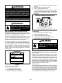
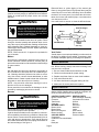
E 2005 Lennox Industries Inc.
Dallas, Texas, USA
15GCSX Series Units
505,040M
08/05
Armstrong #38152A066
WARNING
Improper installation, adjustment, alteration,
service or maintenance can cause property
damage, personal injury or loss of life. Installation and service must be performed by a
qualified installer, service agency or the gas
supplier
READ ALL INSTRUCTIONS IN THIS MANUAL
AND RETAIN FOR FUTURE REFERENCE
Litho U.S.A.
E2005
WARNING
FIRE OR EXPLOSION HAZARD.
Failure to follow safety warnings exactly could result in serious injury, death,
or property damage.
Do not store or use gasoline or other
flammable vapors and liquids in the
vicinity of this or any other appliance.
Installation and service must be
performed by a qualified installer,
service agency or the gas supplier.
08/05
*2P0805*
WHAT TO DO IF YOU SMELL GAS:
D Do not try to light any appliance.
D Do not touch any electrical switch; do not
use any phone in your building.
D Leave the building immediately.
D Immediately call your gas supplier from a
neighbor’s phone. Follow the gas supplier’s
instructions.
D If you cannot reach your gas supplier, call
the fire department.
505,040M
*P505040M*
15GCSX Parts Arrangement
R
Safety Information
1 − Keep unit area clear and free of combustible materials, gasoline and other flammable vapors and liquids.
2 − Inspect return air duct to ensure duct is sealed to
the unit and terminates outside the space containing appliance.
3 − This unit requires air for combustion and ventilation
to ensure both proper and safe operation. Combustion air is brought in through the condenser section.
Do not block or obstruct the condenser coil or condenser fan opening.
4 − Examine the unit periodically to ensure that the physical support of the unit is sound without sagging,
cracks, gaps, etc. There must be no obvious signs of
deterioration of the unit.
WARNING
Electric shock hazard. Can cause
injury or death. Before attempting to
perform any service or maintenance,
turn the electrical power to unit OFF at
disconnect switch(es). Unit may have
multiple power supplies.
WARNING
Danger of explosion. Can cause injury
or product or property damage. Should
the gas supply fail to shut off or if
overheating occurs, shut off the gas
valve to the unit before shutting off the
electrical supply.
Page 1
WARNING
Product contains fiberglass wool.
Disturbing the insulation in this product during
installation, maintenance, or repair will expose you
to fiberglass wool. Breathing this may cause lung
cancer. (Fiberglass wool is known to the State of
California to cause cancer.)
Fiberglass wool may also cause respiratory, skin,
and eye irritation.
To reduce exposure to this substance or for further
information, consult material safety data sheets
available from address shown below, or contact
your supervisor.
P.O. Box 799900
Dallas, TX 75379−9900
WARNING
Danger of electrical shock, explosion
and fire. Improper servicing could
result in dangerous operation, serious
inujry, death or property damage.
WARNING
Danger of explosion and fire. Failure to
follow safety warnings exactly could
result in dangerous operation, serious
injury, death or property damage.
WARNING
Do not use this unit if any part has been under water. A flood−damaged unit is extremely dangerous.
Attempts to use the unit can result in fire or explosion. A qualified service agency should be contacted to inspect the unit and to replace all gas
controls, control system parts, electrical parts that
have been wet orto replace the unit if deemed necessary.
4 − Turn the gas valve knob to the ON position. Refer to
figure 2.
5 − Replace heat section access panel.
6 − Turn on electrical power to unit.
7 − Set room thermostat to desired temperature. (If thermostat setpoint temperature is above room temperature after the pre−purge time expires, main burners
will light).
Honeywell VR8205 Series Gas Valve
Unit Operation
WARNING
Danger of explosion and fire. Can
cause injury or product or property
damage. You must follow these
instructions exactly.
FOR YOUR SAFETY READ BEFORE LIGHTING
BEFORE LIGHTING smell all around the unit area for
gas. Be sure to smell next to the floor because some gas
is heavier than air and will settle on the floor.
Use only your hand to turn the gas control knob. Never
use tools. If the knob will not turn by hand, do not try to
repair it, call a qualified service technician. Force or attempted repair may result in a fire or explosion.
This unit is equipped with an automatic spark ignition system. There is no pilot. In case of a safety shutdown, move
thermostat switch to OFF and return the thermostat
switch to HEAT. An electro−mechanical thermostat is
shown in figure 1. On units with electronic temperature
controls, shut main disconnect off and back on to reset
ignition control.
THERMOSTAT
HEAT
COOL
50 60 70 80
10 15 2025 30
FAN
AUTO
ON
HEAT OFF COOL
Figure 1
To Place Unit into Operation:
1 − Turn off electrical power to unit.
2 − Set thermostat to lowest setting.
3 − Remove heat section access panel.
GAS VALVE SHOWN IN OFF POSITION
Figure 2
To Shut Down:
1 − Set the thermostat to the lowest setting.
2 − Turn off electric power to unit.
3 − Remove heat section access panel.
4 − Turn the gas valve knob to the OFF position.
5 − Replace heat section access panel.
WARNING
Danger of explosion. Can cause injury
or death. Do not attempt to light
manually. Unit has a direct spark
ignition system.
Thermostat Operation
There are many styles of thermostats. Though their appearances may be different, there are many similarities.
System Switch
The thermostat system switch allows you to choose
whether you wish the unit to operate in either the HEAT or
COOL mode. When the HEAT mode is selected, the unit
will operate to satisfy a heating demand. When the COOL
mode is selected, the unit will operate to satisfy a cooling
demand. Some thermostats feature an AUTO system
mode, which automatically switches between the HEAT
and COOL modes to ensure comfort.
Fan Operation
The thermostat fan switch allows you to choose whether
you wish the circulating air blower to operate in either the
AUTO or ON mode. When the AUTO mode is selected,
the circulating air blower will cycle on and off with the cooling or heating demand. When the ON mode is selected,
the circulating air blower will operate continuously.
Page 2
Maintenance
To maintain efficiency and longevity, your equipment
must be serviced yearly by a qualified service technician.
Failure to provide proof of proper service can void the
warranty.
WARNING
Distorted flame or yellow tipping of the natural gas
flame (or long yellow tips on LP/propane flame) may be
caused by one or more of the following: lint or dirt inside
the burner or burner ports; lint or dirt at the air inlet between the burner and manifold pipe; or an obstruction
over the burner orifice.
Use a soft brush or vacuum to clean the affected areas.
Typical Flame Appearance
Electric shock hazard. Can cause
injury or death. Before attempting to
perform any service or maintenance,
turn the electrical power to unit OFF at
disconnect switch(es). Unit may have
multiple power supplies.
Heat Exchanger
Burner
Filters
Filter(s) must be installed in the return air system. Filters
should be checked monthly and replaced when necessary. Take note of air flow direction marking on filter frame
when reinstalling filters. Replace disposable or clean permanent type as necessary. DO NOT replace permanent
type with disposable.
NOTE − Filters must be U.L.C. approved or equivalent for
use in Canada.
Motors
All motors are permanently lubricated and require no
further lubrication. Motors should be cleaned yearly to
prevent the accumulation of dust and dirt on the windings
or motor exterior.
Coil
Dirt and debris should not be allowed to accumulate on
the coil surfaces or other parts in the air conditioning circuit. Cleaning should be performed as often as necessary. Use a brush, vacuum cleaner attachment, or other
suitable means. If water is used to clean the coil, be sure
the power to unit is shut off prior to cleaning.
NOTE − Care should be used when cleaning the coil so
that the coil fins are not damaged.
Do not permit the hot condenser air discharge to be obstructed by overhanging structures or shrubs.
Burners
WARNING
Danger of explosion and fire. Can cause
injury or product or property damage.
Periodically inspect burner flame to ensure proper unit operation.
Inspect the burner flame periodically during heating season to ensure proper burner operation.
Light the burners and allow unit to operate for a few minutes to establish normal burning conditions. Observe the
burner flames. Flames should be predominantly blue in
color and strong in appearance. Verify that all burners
are lit and that the flame does not impinge on the sides of
the heat exchanger. See figure 3.
Burner
Flame
Gas Manifold
(Blue Only)
Figure 3
Vent Outlet
Visually inspect vent outlet periodically to make sure that
the there is no buildup of soot and dirt . If necessary, clean
to maintain adequate opening to discharge flue products.
Service Reminder
Call a qualified service technician if the unit is inoperative. Before calling, always check the following to be
sure service is required:
1 − Be sure electrical disconnect switches are ON.
2 − Check room thermostat for proper setting.
3 − Replace any blown fuses or reset circuit breakers.
4 − Gas valve should be ON.
5 − Air filters should not be plugged, limiting air flow.
6 − Make sure all access panels are in place.
Repair Parts List
The following repair parts are available through Lennox
dealers. When ordering parts, include the complete unit
model number listed on the unit rating plate.
CONTROL PANEL PARTS HEATING PARTS
Ignition control board
Heat exchanger assembly
Contactor
Combustion air inducer
Transformer
Orifices
Capacitor
Burners
BLOWER PARTS
Gas valve
Blower wheel
Manifold
Blower Motor
Ignitor
Motor mounting arm
Limit control
Blower housing
Rollout switch
COOLING PARTS
Pressure switch
Compressor
Condenser fan motor/blades
Coils
Drain pan
Page 3