1
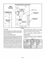
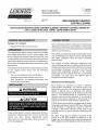
[fT _ _ Technical
_LJ_ Publications
HEAT PUMP KITS
AND ACCESSORIES
@1995 Lennox
Industries
Inc.
503,214M
1/95
Dallas, Texas
INSTALLATION
REPLACEMENT DEFROST
CONTROL BOARD
INSTRUCTIONS
FOR REPLACEMENT
DEFROST CONTROL
(11K71) USED WITH HP29, 10HPB, 12HPB SERIES UNITS
Package 1 of I contains:
1- Replacement
Litho U.S.A.
defrost control
The unit's defrost system includes two components; a
defrost thermostat (see unit installation instructions)
board
and a defrost control. The following
defrost control functions.
The replacement defrost control board for the HP29
and 10HPB series units is part number 68J84. This
board replaces the original control board with part
number 68J24. Unit wiring to the defrost board is the
same. More options are provided in the replacement
board such as ambient thermistor and service light
connections.
The replacement
as the original
functions:
board has the same basic functions
board along with the following
five minute compressor
anti-short
BOARD KIT
delay;
pressure switch safety lockout circuit; and
field connection
for ambient
thermistor
service light connections.
section describes
The defrost control board has the combined
functions
of a time/temperature
defrost control, defrost relay,
time delay, diagnostic
LEDs and field connection
terminal strip.
The control
provides
automatic
switching
from
normal heating operation to defrost mode and back.
During compressor cycle (call for defrost), the control
accumulates compressor
run times at 30, 60 or 90
minute
field adjustable
intervals.
If the defrost
thermostat
remains closed when the accumulated
compressor
run time ends,
energized and defrost begins.
the
defrost
relay
is
and
Defrost
Control
Timing
Pins
Each timing
pin selection
provides
a different
accumulated
compressor
run period during one
thermostat
run cycle. This time period must occur
before a defrost
cycle is initiated.
The defrost
interval can be adjusted to 30, 60 or 90 minutes. See
figure 1. The defrost period is a maximum
of 14
minutes and cannot be adjusted.
If no timing is
selected, the control defaults to 90 minutes. The
factory and recommended
setting is 60 minutes.
WARNING
CAUTION
The provided board is a direct replacement. Remove
wires from original board and remove board from
control
box area. Secure
replacement
board
stand-offs into mounting holes. Wire as shown on
unit wiring diagram.
A TEST option is provided for troubleshooting.
When
the jumper is placed across the TEST pins, the timing
of all functions
is reduced by a factor of 128. For
example, a 90 minute interval during TEST is 42
seconds and the 14 minute defrost is reduced to 6.5
seconds.
The TEST mode may be started at anytime. If the
jumper is in the TEST position at power-up or for
longer than five minutes, the control will ignore the
TEST selection and will default to a 90 minute interval.
Page 1
REPLACEMENT DEFROST CONTROL BOARD
PRESSURE
SWITCH
SAFETY CIRCUIT
CONNECTIONS
/
CONNECTION
ONE OPTIONAL
DIAGNOSTIC
LEDs
FOR
DEFROST INTERVAL
SWITCH
TIMING
PS2
PINS
PS1
24V TERMINAL
CONNECTIONS FOR
TWO OPTIONAL
SWITCHES
[]
STRIP
CONNECTIONS
SERVICE LIGHT
.......
ps2
Psi
ONNECT,ON
.........................
.........................
FIGURE 1
Time-Delay
The timed-off
delay is five minutes long. The delay
feature is provided to help protect the compressor in
case of an interruption
in power to the unit or when a
pressure switch resets.
Pressure
Switch
Safety
Circuit
control board. See figure 1. When only one pressure
switch is used, wire the switch to the two outside
terminals of the pressure switch connections.
NOTE: If not
factory-installed
Diagnostic
The defrost control incorporates a pressure switch
safety circuit that allows the application of up to two
optional pressure switches; high pressure and/or loss
of charge. See figure 1. During a demand cycle, the
defrost control will lock out the unit on the third
instance that the unit goes off on any pressure switch
wired to this circuit. The diagnostic LEDs will display a
pattern for a lockout pressure switch on the third
open pressure switch occurrence. See table 1. The
unit will remain locked out until the switch is reset.
using
jumper
a pressure
switch,
the
wire must be connected.
LEDs
The defrost board uses two LEDs for diagnostics.
The LEDs flash a specific sequence according to the
condition.
TABLE 1
Remove factory-installed
jumper before connecting
optional pressure switches to control board. When
two pressure switches are used, wire each switch to
one set of terminals PS1 and PS2 on the defrost
Page 2
DEFROST CONTROL
MODE
BOARD DIAGNOSTIC
LED 1
LED
LED 2
Normal Operation/
Power to board
Flash together
with LED 2
Flash together
with LED 1
_me Delay
To Protect Compressor
Alternating
Flashes
with LED 2
Alternating
Flashes
with LED 1
Pressure Switch Open
Off
On
Pressure Switch Lockout
On
Off
Board Malfunction
On
On