1
HP29
Corp. 0101−L1
Revised 06−2003
Service Literature
Heat Pumps−7.5 &10 Ton
(26.4 & 35.2 kw)
Litho U.S.A.
HP29 HEAT PUMP SERIES
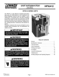
The HP29 7.5 and 10 (26.4 and 35.2 kW) ton heat pump
units are designated for light commercial applications, with
a remotely located blower−coil unit or a furnace with an
add−on evaporator coil. HP29 model units are equipped
with a scroll compressor. The HP29 heat pumps match
with the CB/CBH17 blower−coil units. All HP29 units are
three−phase.
This manual is divided into sections which discuss the ma
jor components, refrigerant system, charging procedure,
maintenance and operation sequence.
Information in this manual is intended for qualified service
technicians only. All specifications are subject to change.
Procedures in this manual are presented as recommenda
tions only and do not supersede or replace local or state
codes.
HP29−090
WARNING
WARNING
Refrigerant can be harmful if it is inhaled. Refriger
ant must be used and recovered responsibly.
Failure to follow this warning may result in person
al injury or death.
Improper installation, adjustment, alteration, ser
vice or maintenance can cause property damage,
personal injury or loss of life. Installation and service
must be performed by a qualified installer or service
agency.
TABLE of CONTENTS
Introduction . . . . . . . . . . . . . . . . . . . . Page 1
IV CHARGING . . . . . . . . . . . . . . . . . Page 15
Specifications / Electrical . . . . . . . . Page 2
Leak Testing . . . . . . . . . . . . . . . . . . . Page 15
Parts Arrangement . . . . . . . . . . . . . . Page 4
Evacuating . . . . . . . . . . . . . . . . . . . . . Page 16
I UNIT COMPONENTS . . . . . . . . . . Page 6
Charging . . . . . . . . . . . . . . . . . . . . . . Page 17
Control Box . . . . . . . . . . . . . . . . . . . . Page 6
V MAINTENANCE . . . . . . . . . . . . . . Page 19
Cooling . . . . . . . . . . . . . . . . . . . . . . . . Page 7
VI WIRING & OPERATION SEQUENCE
Defrost System . . . . . . . . . . . . . . . . . Page 9
HP29−090 . . . . . . . . . . . . . . . . . . . . . . Page 20
II REFRIGERANT . . . . . . . . . . . . . . . Page 13
HP29−120 . . . . . . . . . . . . . . . . . . . . . . .Page 23
III START UP . . . . . . . . . . . . . . . . . . . Page 14
Thermostat Connections . . . . . . . . . .Page 26
Page 1
2001 Lennox Industries Inc.
Litho U.S.A.
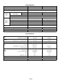
SPECIFICATIONS
Model No.
HP29−090−2
HP29−120−2
7.5 (26.4)
10 (35.2)
Nominal Size − Tons (kW)
Liquid line (o.d.) in. (mm) connection (sweat)
5/8 (15.9)
Vapor line (o.d.) in. (mm) connection (sweat)
Outdoor
Coil
Net face area sq. ft. (m2)
1−3/8 (34.9)
Outer coil
21.80 (2.03)
Inner coil
20.94 (1.95)
Tube diameter in. (mm) & no. of rows
−−−−
3/8 (9.5) − 2
Fins per inch (m)
20 (787)
Diameter in. (mm) & no. of blades
Outdoor
Coil
F ( )
Fan(s)
(2) 29.34 (2.73)
(1) 24 (610) − 4
(2) 24 (610) − 3
Motor hp (W)
(1) 1/2 (373)
(2) 1/3 (249)
Cfm (L/s) total air volume
5300 (2500)
8200 (3870)
Rpm
1075
1100
Motor Input − Watts
350
700
Refrigerant charge
dry air
Shipping weight lbs. (kg) 1 package
506 (230)
604 (284)
83K37
79K91
OPTIONAL ACCESSORIES – Must Be Ordered Extra
Hail Guards
SPECIFICATIONS
G
General
D
Data
Connections
(
(sweat)
t)
Model No.
10 (35.2)
Liquid line (o.d.) − in. (mm) connection
5/8 (15.9)
5/8 (15.9)
Vapor line (o.d.) − in. (mm) connection
1−3/8 (34.9)
1−3/8 (34.9)
dry air holding charge
dry air holding charge
Net face area − sq. ft. (m2) Outer coil
30.0 (2.79)
(2) 29.34 (2.73)
Inner coil
28.94 (2.69)
−−−
Tube diameter − in. (mm) & no. of rows
3/8 (9.5) − 2
3/8 (9.5) − 2
20 (787)
20 (787)
Fins per inch (m)
Outdoor
C il
Coil
Fan(s)
Shipping
HP29−120−3
7.5 (26.4)
Refrigerant
Outdoor
C il
Coil
HP29− 090−3
Nominal Size − Tons (kW)
Diameter − in. (mm) & no. of blades
(1) 24 (610) − 4
(2) 24 (610) − 3
Motor hp (W)
(1) 3/4 (560)
(2) 1/3 (249)
cfm (L/s) total air volume
5400 (2550)
8200 (3870)
Rpm
1075
1100
Motor Input − Watts
600
700
lbs. (kg) 1 package
485 (220)
604 (284)
29M45
79K91
OPTIONAL ACCESSORIES – Must Be Ordered Extra
Hail Guards
Page 2
ELECTRICAL DATA
Model No.
HP29−090−2
Line voltage data 60 hz − 3 phase
HP29−120−2
208/230v
460v
575v
208/230v
460v
575v
Rec. max. fuse or circuit breaker size (amps)
60
30
25
80
40
25
{Minimum circuit ampacity
39
20
15
53
25
18
Rated load amps
28.8
14.7
10.8
37.8
17.2
12.4
Locked rotor amps
195
95
80
239
125
80
Full load amps (total)
3
1.5
1.2
2.4 (4.8)
1.3 (2.6)
1 (2)
Locked rotor amps (total)
6
3
2.9
4.7 (9.4)
2.4 (4.8)
1.9 (3.8)
C
Compressor
(1)
Outdoor Coil
FanMotor (1 phase)
{Refer to National or Canadian Electrical Code manual to determine wire, fuse and disconnect size requirements.
NOTE Extremes of operating range are plus and minus 10% of line voltage.
HACR type (under 100 amps). U.S. only.
ELECTRICAL DATA
G
General
D
Data
Model No.
Line voltage data − 60 hz − 3 phase
Compressor (1)
Outdoor Coil
Fan Motor (1 phase)
FanMotor
HP29−090−3
HP29−120−3
208/230v
460v
575v
208/230v
460v
575v
Rec. max. fuse or circuit breaker size (amps)
60
35
25
80
40
25
{Minimum circuit ampacity
40
21
16
53
25
18
Rated load amps
28.8
14.7
10.8
37.8
17.2
12.4
Locked rotor amps
195
95
80
239
125
80
Full load amps (total)
3.7
1.9
1.6
2.4 (4.8)
1.3 (2.6)
1 (2)
Locked rotor amps (total)
7.3
3.7
3.4
4.7 (9.4)
2.4 (4.8)
1.9 (3.8)
{Refer to National or Canadian Electrical Code manual to determine wire, fuse and disconnect size requirements.
NOTE Extremes of operating range are plus and minus 10% of line voltage.
HACR type (under 100 amps). U.S. only.
Page 3
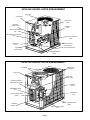
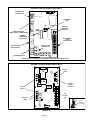
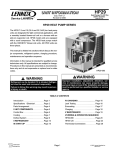
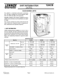
HP29−090−3 MODEL PARTS ARRANGEMENT
fan guard
control box
outdoor fan
(B4)
vapor line
service valve
reversing
valve
defrost thermostat
(S6)
discharge line thermostat
(S5)
high pressure switch
(S4)
compressor
(B1)
defrost pressure
switch (S46)
loss of charge switch (S24)
liquid line
service valve
low ambient switch
(S11)
FIGURE 1
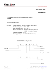
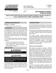
HP29−120−3 MODEL PARTS ARRANGEMENT
outdoor fans
(B4, B5)
fan guard
control box
vapor line
service valve
defrost thermostat
(S6 [S124 not shown])
reversing
valve
low ambient switch
(S11)
compressor
(B1)
loss of charge switch
(S24)
defrost pressure switch
(S46)
liquid line
service valve
high pressure switch
(S4)
FIGURE 2
Page 4
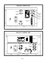
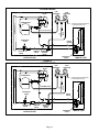
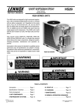
HP29−090−3 CONTROL BOX
transfer relay
K8
low ambient
kit relay
K58
outdoor fan
relay K10
defrost relay
K4
CMCI
defrost/timer
R
latch relay
K6
G
G1
ground
lug
capacitor C1
terminal strip
TB 14
compressor
contactor
K1
W1
W2
Y1
C
FIGURE 3
HP29−120−3 CONTROL BOX
relay switch
K6
terminal strip
TB 14
cmc1 defrost / timer
outdoor fan
relay K10
transfer relay
K8
capacitors
C1, C2
ground
lug
outdoor fan
relay K68
compressor
contactor K1
low ambient
thermostat S41
FIGURE 4
Page 5
low ambient by−
pass realy
K58
defrost relay
K4
I−UNIT COMPONENTS
A latch relay (figure 5 ) has two coils: a SET" coil and a
The HP29−090 and HP29−120 components are shown in
figures 1 and 2.
RESET" coil. When 24VAC is applied to the SET" coil, the
A−CONTROL BOX COMPONENTS
The HP29−090 control box components are shown in fig
ure 3. The HP29−120P control box components are shown
in figure 4.
normally open contacts close and the normally closed con
tacts open. When power is removed from the SET" coil,
nothing happens; the NO. contacts remain closed and the
N.C. contacts remain open. The contacts do not return to
1 − Disconnect Switch S48
(Option −2 Units)
their normal position until the RESET" coil is energized.
HP29 heat pumps units may be equipped with an optional
disconnect switch S48. S48 is a factory−installed toggle
switch used to disconnect power to the unit.
position when power is removed.
Once the contacts are reset, they remain in their normal
HP29 units use a DPDT
2 − Outdoor Fan Capacitors C1 (all units)
and C2 (120P)
latch relay. Each set of nor
All HP29 units use single−phase condenser fan motors.
Motors are equipped with a fan run capacitor to maximize
motor efficiency. Outdoor fan capacitors C1 and C2 assist
in the start up of condenser fan motors B4 and B5. Capaci
tor ratings are on outdoor fan motor nameplates.
LATCH RELAY K6
mally open contacts con
trols a reversing valve.
When the SET" coil is en
ergized, the normally open
3 − Compressor Contactor K1 (all units)
contacts close to energize
All compressor contactors are three−pole−double break
contactors with a 24V coil. K1 energizes compressor B1 in
both HP29−090 and HP29−120 units. The contactor is en
ergized from indoor thermostat terminal Y when thermo
stat demand is present.
the reversing valve (there
by placing the unit in the
1
4
cooling mode). When pow
er is removed from the
5
4 − Low Ambient Thermostat S41
(HP29−120 only)
6
8
9
SET" coil (such as when
thermostat demand is satis
10
12
fied), the normally open
14
contacts remain closed, the
S41 is a N.C. limit which opens on temperature fall at 55+
5_F. The switch resets when temperature rises to 65+ 6_F.
S41 opens and de−energizes K68 which de−energizes out
door fan B5. When S41 closes, fans will be re−energi
zed.This intermittent fan operation increases indoor evap
orator coil temperature to prevent icing.
SET
reversing valve remains en
FIGURE 5
mains in the cooling mode.
ergized and the unit re
5 − Latch Relay K6 (all units)
When a heating demand is initiated, the RESET" coil is
HP29 units are plumbed so that the unit is in cooling mode
when the reversing valve is energized. Latch relay K6 con
trols operation of the reversing valve and is controlled (indi
rectly) by the indoor thermostat. The combined operation
of latch relay K6 and transfer relay K8 allows the HP29
heat pumps to use a conventional heat/cool thermo
stat instead of a heat pump thermostat.
energized. The normally open contacts open and the re
RESET
13
versing valve is deenergized (thereby placing the unit in
the heating mode). When heat demand is satisfied and
power to the RESET" coil is removed, the normally open
contacts remain open, the normally closed contacts re
main closed and the unit remains in the heating mode.
Page 6
6 − Transfer Relay K8 (all units)
B−COOLING COMPONENTS
Transfer relay K8 ensures that the indoor blower will oper
ate during all modes of operation. K8 also completes the
circuit to Y1 on the defrost control board CMC1. The com
bined operation of latch relay K6 and transfer relay K8 al
lows the HP29 unit to use a conventional heat/cool thermo
stat instead of a heat pump thermostat. When there is a de
mand for cooling, K8−1 closes completing the Y1 circuit to
defrost control board CMC1 terminal Y1. Normally open
K6−1 closes energizing the reversing valve. K8−2 normaly
closed contacts ensure an unbroken circuit between in
door thermostat "G" and indoor blower contactor through
terminals "G" and "G1" on terminal strip TB14. When there
is a heat demand, normally closed K8−1 opens breaking
the Y1 circuit to the defrost control CMC1. Power is sent to
the "RESET" coil on K6. K6−1 opens de−energizing the re
versing valve. K8−2 closes sending voltage from "G1" to
the indoor blower control.
IMPORTANT
ALL major components (indoor blower/coil) must
be matched to Lennox recommendations for com
pressor to be covered under warranty. Refer to En
gineering Handbook for approved system match
ups.
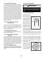
1 − Scroll Compressor B1
All HP29 units utilize a
scroll compressor.
is simple, efficient and re
SCROLL COMPRESSOR
DISCHARGE
quires few moving parts.
A cutaway diagram of the
scroll
7 − Outdoor Fan Relay K10 (all units)
K68 (HP29−120)
The
scroll compressor design
compressor
is
SUCTION
shown in figure 6. The
scrolls are located in the
Outdoor fan relay K10 is a DPDT relay and K68 is a SPDT
relay with a 24V coil. In all units K10 energizes outdoor fan
B4 (fan 1) in response to thermostat demand. In the
HP29−120, K68 energizes outdoor fan B5 (fan 2) in re
sponse to thermostat demand.
top of the compressor can
and the motor is located in
the bottom of the com
pressor can. The oil level
is immediately below the
FIGURE 6
8 − Terminal Strip TB14 (all units)
motor and oil is pressure
TB14 terminal strip distributes 24V power from the thermo
stat to control box components.
fed to the moving parts of the compressor. The lower portion
of the compressor shell is exposed to low side pressure while
only the very top of the shell is exposed to high side pressure.
9 − Low Ambient Bypass Relay K58
(all units)
K58 is a normally closed DPDT relay with a 24V coil, used
in both HP29−090 and HP29−120 units. K58 is wired paral
lel with the reversing valve L1. When L1 is energized in the
cooling cycle, K58 is also energized, opening K58−1. On
the HP29−120, K58−1 and K58−2 will open. This shuts off
power to the outdoor fans but does not by−pass S11 and
S41, which allow fans to cycle during cooling demand. Dur
ing heating demand, K58 remains closed by−passing S11
and S41 so fans can operate.
10 − GFI− J11 (Optional −2 units)
HP29 units may be equipped with a 110v ground fault in
terrupter (GFI). The GFI is located on the control box panel
on the HP29. Separate wiring must be run for the 110v re
ceptacle.
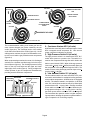
The scroll is a simple compression concept centered
around the unique spiral shape of the scroll and its inherent
properties. Figure 7 shows the basic scroll form. Two iden
tical scrolls are mated together forming concentric spiral
shapes (figure 9). One
scroll remains station
ary, while the other is al
lowed to orbit (figure
8−1). Note that the orbit
ing scroll does not rotate
or turn but merely orbits
the stationary scroll.
FIGURE 7
Page 7
SUCTION
SUCTION
INTERMEDIATE PRESSURE
GAS
2
1
CRECENT SHAPED
ORBITING SCROLL
GAS POCKET
STATIONARY SCROLL
SUCTION
FLANKS SEALED
POCKET
BY CENTRIFIGUAL
FORCE
SUCTION
SUCTION
MOVEMENT OF ORBIT
3
4
HIGH PRESURE GAS
DISCHARGE
POCKET
FIGURE 8
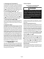
The counterclockwise orbiting scroll draws gas into the
2 − Crankcase Heaters HR1 (all units)
outer crescent shaped gas pocket created by the two
All HP29 units use a belly−band crankcase heater. Heater
scrolls (figure 8−2). The centrifugal action of the orbiting
HR1 is wrapped around compressor B1. HR1 assures
scroll seals off the flanks of the scrolls (figure 8−3). As the
proper compressor lubrication at all times.
orbiting motion continues, the gas is forced toward the cen
3 − High Pressure Switch S4 (all units)
ter of the scroll and the gas pocket becomes compressed
The high pressure switch is a manual−reset SPST N.C.
(figure 8−4).
switch which opens on a pressure rise. The switch is lo
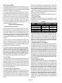
When compressed gas reaches the center, it is discharged
cated on the compressor discharge line and is wired to the
vertically into a chamber and discharge port in the top of
defrost control board CMC1. When discharge pressure
the compressor (figure 6). The discharge pressure forcing
rises to 450 + 10 psig (3103 + 69 kPa) the switch opens and
down on the top scroll helps seal the upper and lower
the compressor is de−energized through the CMC1. The
edges (tips) of the scrolls (figure 9). During a single orbit,
switch will close when discharge pressure drops to 300 +
several pockets of gas are compressed simultaneously
20 psig (2068 + 138 kPA).
providing smooth continuous compression.
4 − Low Ambient Switch S11 (all units)
CROSS−SECTION OF SCROLLS
DISCHARGE
PRESSURE
DISCHARGE
STATIONARY SCROLL
SUCTION
TIPS SEALED BY
DISCHARGE PRESSURE ORBITING SCROLL
FIGURE 9
The low ambient switch is an auto−reset SPST N.O. pres
sure switch, which allows for mechanical cooling operation
at low outdoor temperatures. All HP29 units are equipped
with S11. The switch is located in the liquid line. In all HP29
units, S11 is wired in series with fan relay K10. When liquid
pressure rises to 275 + 10 psig (1896 + 69 kPa), the switch
closes and the condenser fan is energized. When the dis
charge pressure drops to 150 + 10 psig (1034 + 69 kPa),
the switch opens and the condenser fan is de−energized.
This intermittent fan operation results in higher evaporat
ing temperature, allowing the system to operate without ic
ing the evaporator coil and losing capacity.
Page 8
5 − Discharge Line Thermostat S5
C−Defrost System
S5 is an automatic reset SPST N.C. switch which opens on
a temperature rise. The switch is located on the discharge
line and wired in series with the CMCI board and S4 pres
sure switch. When discharge line temperature rises to
275° + 5°F the switch opens and the compressor is de−en
ergized through the CMCI. The switch automatically resets
when discharge temperature drops to 225° + 5°F.
6 − Loss of Charge Switch S24
The loss of charge switch is an auto−reset SPST N.O.
switch, which opens on pressure drop. The switch is lo
cated on the liquid line and is wired to the defrost control
board CMC1. When liquid pressure drops to 25 + 5 psig
(172 + 34 kPa), the switch opens and the compressor is de−
energized. The switch automatically resets when pressure
in the liquid line rises to 55 + 5 psig (379 + 34 kPa).
7 − Reversing Valve L1 (all units)
A reversing valve with an electromechanical solenoid is
used to reverse refrigerant flow during unit operation. L1 is
energized during cooling demand and defrost. See figures
12 and 13.
8 − Expansion Valves
The HP29−120−2 uses two expansion valves in the liquid
line adjacent to the left and right refrigerant coil. The
HP29−090−2 units have one expansion valve. Aliquid line
filter/drier and check valve are connected in parallel with
each expansion valve. The check valve allows for reverse
refrigerant flow. The HP29−120−3 uses two internally
checked expansion valveand the HP29−090−3 uses one in
ternally checked expansion valve. The valves are located
in the liquid line adjacent to the left and right refrigerant coil.
In all units expansion valve control is provided by a super
heat sensing bulb which is connected by a capillary tube to
the expansion valve. The sensing bulb is strapped to the
vapor line where it exits the coil. If the bulb senses low su
perheat, the expansion valve throttles down and restricts
refrigerant flow through the coil. When excessive super
heat is sensed, the valve opens to allow more refrigerant
flow through the coil. See figures 12 and 13.
9 − Condenser Fan B4 (both units)
B5 (HP29−120)
See page 2 for the specifications on the condenser fans
used in the HP29 units. All condenser fans have single−
phase motors. The HP29−090 units are equipped with a
single condenser fan. The HP29−120 is equipped with two
fans. The fan assembly may be removed for servicing by
removing the motor mounts nuts.
Page 9
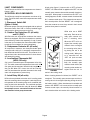
ELECTROSTATIC DISCHARGE (ESD)
Precautions and Procedures
CAUTION
Electrostatic discharge can affect electronic
components. Take precautions during unit instal
lation and service to protect the unit’s electronic
controls. Precautions will help to avoid control
exposure to electrostatic discharge by putting
the unit, the control and the technician at the
same electrostatic potential. Neutralize electro
static charge by touching hand and all tools on an
unpainted unit surface before performing any
service procedure.
The defrost system includes four components: a defrost
thermostat, defrost pressure switch, defrost relay and de
frost control.
Defrost Thermostat Switch S6, S124
Defrost thermostat switches S6 (refrigeration circuit one)
and S124 (refrigeration circuit two) are S.P.S.T. N.O. con
tacts which close on temperature fall (initiating defrost after
minimum run time of 30, 60, or 90 minutes). The switches
are located on each of the expansion valve distributor as
semblies. The switches monitor the outdoor coil saturation
temperature to determine when defrost is needed. When
the outdoor coil temperature falls to 35_ F+ 4_F (1.7_C +
2.2_C), the switch closes (initiating defrost after minimum
run time of 30, 60, or 90 minutes). When the temperature
rises to 60_F + 5_F (15.6_C + 2.8_C), the switch opens.
Defrost Pressure Switch S46
Defrost switch S46 is an auto−reset SPST N.C. pressure
switch which opens on pressure rise of 275 + 10 psi (1896
+ 69 kPa). When S46 opens, defrost operation ends. The
switch will reset when the unit receives a heat call and
pressure falls to 195 + 10 psi (1344 + 69 kPa). All HP29
units are equipped with this switch located on the dis
charge line. See figures 1 and 2. S46 is wired through the
K8 transfer relay to the defrost board CMC1.
Defrost Relay K4
Defrost relay K4 controls defrost in the HP29 units. K4 is
controlled by defrost board CMC1 and defrost pressure
switch S46. When K4 is energized, contacts close and de
frost is initiated.
Defrost Control CMC1
The defrost control board combines functions of a time /
temperature initiated and time / pressure terminated defrost
control, defrost relay, time delay, diagnostic LEDs and field
connection terminal strip. See figure 10.
The control provides automatic switching from normal
heating operation to defrost mode and back. During com
pressor cycle (call for defrost), the control accumulates
compressor run times at 30, 60 or 90 minute field adjust
able intervals. If the defrost thermostat remains closed
when the accumulated compressor run time ends, the de
frost relay is energized and defrost begins. The defrost
cycle is terminated by the defrost pressure switch or in 14
minutes whichever occurs first.
Defrost Control Components
1− Defrost Control Timing Pins
Each timing pin selection provides a different accumu
lated compressor run period during one thermostat run
cycle. This time period must occur before a defrost cycle
is initiated. The defrost interval can be adjusted to 30, 60
or 90 minutes. See figure 10. If no timing is selected, the
control defaults to the factory setting 90 minutes. The de
frost period is a maximum of 14 minutes and cannot be
adjusted.
A TEST option is provided for troubleshooting. When the
jumper is placed across the TEST pins, the timing of all
functions is reduced by a factor of 128. For example, a 90
minute interval during TEST is 42 seconds and the 14−min
ute defrost is reduced to 6.5 seconds.
The TEST mode may be started at anytime. If the jumper is
in the TEST position at power−up or for longer than five min
utes, the control will ignore the TEST selection and will de
fault to a 90 minute interval. In order to test defrost cycle,
defrost thermostat must be closed or jumpered. Once
defrost is initiated, remove jumper immediately. Failure to
remove jumper will reduce defrost time to seconds.
2− Time Delay
The timed−off delay is five minutes long. The delay feature
is provided to help protect the compressor in case of inter
ruption in power to the unit before thermostat demand is
satisfied, or when a pressure switch resets. If thermostat
demand is satisfied and the off cycle is greater than 5 min
utes, the compressor will energize immediately on next
heating or cooling demand.
3− Pressure Switch Safety Circuits
The defrost control incorporates a pressure switch safety
circuit that allows the application of an additional pressure
switch; high pressure switch (S4) is factory−wired to this cir
cuit. See figure 10. PS1 and PS2 terminals are internally
connected in series with a jumper internal to the control
board.
During one demand cycle, the defrost control will lock out
the unit on the third instance that the unit goes off on any
auto−reset pressure switch wired to this circuit. The diag
nostic LEDs will display a pattern for a locked out pressure
switch on the third open pressure switch occurrence. See
table 1. The unit will remain locked out until power is bro
ken then remade to the control.
The PS2 safety circuit terminals are connected to the com
pressor thermostat.
4− Diagnostic LEDs
The defrost board uses two LEDs for diagnostics. The
LEDs flash a specific sequence according to the condi
tion. See table 1.
TABLE 1
DEFROST CONTROL BOARD DIAGNOSTIC LED
MODE
LED 1
LED 2
Normal Operation/
Power to board
Time Delay
To Protect Compressor
Pressure Switch Open
Pressure Switch Lockout
Board Malfunction
Flash together with
LED 2
Alternating Flashes
with LED 2
Off
On
On
Flash together with
LED 1
Alternating Flashes
with LED 1
On
Off
On
5−Anti−Short Cycle
This feature of the board prevents the compressor from be
ing short−cycled which could result in damage. An internal
board timer prevents the compressor from being ener
gized for approximately 5 minutes, after thermostat de
mand is met. During this time off, the system refrigerant
pressure is able to equalize (between low and high sides)
which eases compressor start up.
6−Ambient (outdoor air) Thermistor
The defrost control board has two terminal connections for
an ambient thermistor. The thermistor compensates for
changes in the outdoor air temperature. This change in
temperature can cause thermostat droop. Droop may be
defined as the difference between the room thermostat
set−point and the lowest temperature of the indoor air once
the indoor blower is energized. Cool air (relative to thermo
stat set−point or desired room air temperature) will enter
the home when the indoor blower is energized. The therm
istor raises the thermostat set−point by a fractional amount
(1 or 2° F) to keep the indoor air temperature near the ther
mostat set−point.
7−Service Light Connection
Terminal connections W1, L and C are for the addition of a
thermostat service light. This light can be used with any
thermostat. It is powered from the W1 (second stage heat)
terminal of the indoor thermostat and is controlled by a dis
charge line thermostat (S54). The discharge line thermo
stat will close and activate the service light when discharge
line temperature drops below 110°F 5° during compres
sor operation. The light informs the home owner of a prob
lem with the system (specifically the compressor). When
the light is on, second stage heating may be initiated. The
normally closed thermostat will open when discharge line
reaches 130°F 5° which requires 30 to 40 seconds of
compressor operation, at which time the service light is de−
energized.
Page 10
DEFROST CONTROL BOARD HP29−2 UNITS
COMPRESSOR
CONNECTIONS
DIAGNOSTIC
LEDs
LED
2
DEFROST
INTERVAL
TIMING PINS
PRESSURE SWITCH
SAFETY CIRCUIT CONNECTIONS
AMBIENT
THERMISTOR
CONNECTION
24V TERMINAL
STRIP
CONNECTIONS
SERVICE LIGHT
CONNECTION
DEFROST SWITCH
CONNECTIONS
REVERSING VALVE
NOTE− There is an internal jumper between inside PS1 and PS2 terminals.
FIGURE 10
DEFROST CONTROL BOARD HP29−3 UNITS
service
lights
ambient
thermistor
connection
pressure
switches
24V
terminal
strip
diagnostic
LEDs
timing
jumper
90
60
FIGURE 11
Page 11
test
30
timing pins
(seconds)
COOLING MODE
REVERSING
VALVE
LOW
PRESSURE
HIGH
PRESSURE
COMPRESSOR
ACCUMULATOR
EXPANSION
VALVE
BI−FLOW
DRIER
CHECK
VALVE
INDOOR COIL
TO
REFRIGERANT
DRUM
OUTDOOR COIL
NOTE − ARROWS INDICATE DIRECTION
OF REFRIGERANT FLOW
VAPOR LINE
SERVICE LIQUID LINE
VALVE
SERVICE
VALVE
EXPANSION
VALVE
OUTDOOR UNIT
INDOOR UNIT
FIGURE 12
HEATING MODE
REVERSING
VALVE
LOW
PRESSURE
HIGH
PRESSURE
COMPRESSOR
EXPANSION
VALVE
BI−FLOW
DRIER
CHECK
VALVE
VAPOR LINE
SERVICE
VALVE
INDOOR COIL
ACCUMULATOR
TO
REFRIGERANT
DRUM
OUTDOOR COIL
NOTE − ARROWS INDICATE DIRECTION
OF REFRIGERANT FLOW
LIQUID LINE
SERVICE
VALVE
EXPANSION
VALVE
OUTDOOR UNIT
FIGURE 13
Page 12
INDOOR UNIT
LIQUID LINE SERVICE VALVE (VALVE OPEN)
II− REFRIGERANT SYSTEM
A−Plumbing
INSERT HEX
WRENCH HERE
Field refrigerant piping consists of liquid and vapor lines
from the outdoor unit (sweat connections) to the indoor
evaporator coil (sweat connections). Refer to table 2 for
field−fabricated refrigerant line sizes. Refer to Lennox Re
frigerant Piping manual Corp. #9351−L9 for proper size,
type and application of field−fabricated lines. Separate dis
charge and suction service ports are provided at the com
pressor for connection of gauge manifold during charging
procedure.
STEM CAP
INLET (TO
INDOOR COIL)
VALVE
CORE
OUTLET (TO
COMPRESSOR)
SERVICE PORT
CAP
B−Accumulator
SERVICE PORT
All HP29−2 units are equipped with an accumulator. The
accumulator prevents compressor slugging by holding ex
cess refrigerant and then slowly metering it back into the
system.
TABLE 2
REFRIGERANT LINE SIZES
HP29
UNIT
LIQUID
LINE
VAPOR
LINE
090
5/8 in
(16 mm)
1−3/8 in
(35mm)
5/8 in
(16 mm)
1−3/8 in
(35mm)
120
LIQUID LINE SERVICE VALVE (VALVE CLOSED)
RETAINING RING
(−2 units only)
STEM CAP
INLET (TO
INDOOR COIL)
INSERT HEX
WRENCH HERE
SERVICE
PORT
(VALVE FRONT
SEATED)
SERVICE PORT
CAP
VALVE CORE OPEN
TO LINE SET WHEN VALVE IS
CLOSED (FRONT SEATED)
C−Service Valves
All HP29 units are equipped with service valves located in
the liquid and vapor lines. The service valves are manually
operated. See figures 14 and 15. The service ports are
used for leak testing, evacuating, charging and checking
charge.
OUTLET (TO
COMPRESSOR)
FIGURE 14
To Access Service Port:
1 − Remove service port cap with an adjustable wrench.
2 − Connect gauge to the service port.
1 − Liquid Line Service Valve
A fullservice liquid line valve made by one of several
manufacturers may be used. All liquid line service valves
function the same way, differences are in construction.
Valves are not rebuildable. If a valve has failed, it must be
replaced. The liquid line service valve is illustrated in figure
14.
A schrader valve is factory installed. A service port cap is
supplied to protect the schrader valve from contamination
and to serve as primary leak seal.
Page 13
3 − When testing is completed, replace service port cap.
Tighten finger tight, then an additional 1/6 turn. Do not
over−torque.
Open Liquid Line Service Valve:
1 − Remove stem cap with an adjustable wrench.
2 − Using service wrench and 5/16" hex head extension (part
#49A71) back the stem out counterclockwise until the
valve stem just touches the retaining ring. Make sure
wrench fits properly to avoid stripping stem.
3 − Replace stem cap. Tighten finger tight, then tighten an
additional 1/6 turn.
DANGER
Do not attempt to backseat this valve past the
retaining ring. Attempts to backseat this valve past
the retaining ring will cause snap ring to explode
from valve body under pressure of refrigerant.
Personal injury and unit damage will result.
VAPOR LINE SERVICE VALVE
USE ADJUSTABLE WRENCH
ROTATE STEM CLOCKWISE 90_ TO CLOSE
ROTATE STEM COUNTERCLOCKWISE 90_ TO OPEN
STEM CAP
TO INDOOR COIL
STEM
To Close Liquid Line Service Valve:
BALL
(SHOWN OPEN)
1 − Remove stem cap with an adjustable wrench.
TO OUTDOOR COIL
2 − Using service wrench and 5/16" hex head extension (part
#49A71) turn stem clockwise to seat the valve. Tighten
firmly.
SERVICE
PORT CAP
3 − Replace stem cap. Tighten finger tight, then tighten an
additional 1/6 turn.
SERVICE PORT
VALVE CORE
2 − Vapor Line Service Valve
HP29 units are equipped with a full service ball valve
shown in figure 15. The valve has one service port that
contains a valve core. A cap is provided to seal off the port
and prevent contamination.
Different manufacturers of valves may be used. All vapor
line service valves function the same way; differences are
in construction. If a valve fails it must be replaced.
To Access Service Port:
1 − Remove service port cap with an adjustable wrench.
2 − Connect gauge to the service port.
3 − When testing is completed, replace service port
cap. Tighten finger tight, then tighten an additional
1/6 turn.
To Open Vapor Line Service Valve:
1 − Remove stem cap with an adjustable wrench.
2 − Back the stem out counterclockwise for a 1/4 turn.
3 − Replace stem cap and finger tighten, then tighten an
additional 1/6 turn.
To Close Vapor Line Service Valve:
1 − Remove stem cap with an adjustable wrench.
2 − Turn stem in clockwise for 1/4 turn.
3−
Replace stem cap. Tighten finger tight, then tighten an
additional 1/6 turn.
FIGURE 15
III−STARTUP
The following is a general procedure and does not apply to
all thermostat control systems. Refer to sequence of op
eration in this manual for more information.
WARNING
Crankcase heaters must be energized for 24 hours
before attempting to start compressors. Set ther
mostat so there is no compressor demand before
closing disconnect switch. Attempting to start
compressors during the 24−hour warm −up period
could result in damage or failed compressors.
1 − Rotate the fan to check for frozen bearings or binding.
2 − Inspect all factory and field−installed wiring for loose
connections.
3 − Refer to section IV− to accurately charge and check
the charge on this unit.
4 − Check voltage supply at the disconnect switch. The
voltage must be within range listed on unit nameplate.
If not, do not start equipment until the power company
has been consulted and the voltage condition cor
rected.
5 − Set thermostat for a cooling demand, turn on power to
blower and close heat pump unit disconnect switch to
start.
6 − Recheck unit voltage with unit running. Power must be
within range shown on unit nameplate. Check amper
age draw of unit. Refer to unit nameplate for correct
running amps.
Page 14
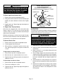
Three−Phase Compressor Rotation
Threephase scroll compressors must be phased se
quentially to ensure that the compressor rotates and
operates correctly. When the compressor starts, a rise
in discharge and drop in suction pressures indicate
proper compressor phasing and operation. If dis
charge and suction pressures do not perform normal
ly, follow the steps below to correctly phase in the unit.
1 − Disconnect the power to the unit.
2 − Reverse any two field power leads to the unit.
3 − Reconnect the power to the unit.
The discharge and suction pressures should operate with
in their normal startup ranges.
NOTE − The compressor’s noise level will be significantly
higher when the phasing is incorrect. The compressor will
not provide cooling when the unit is not correctly phased.
Continued backward operation of the compressor to due to
incorrect phasing will cause the compressor to cycle on in
ternal protector.
IV− CHARGING
HP29 units are field charged with the amount of HCFC−22
refrigerant indicated in the charging procedure. This
charge is based on a matching indoor coil and outdoor coil
with a 25 foot (7.6 m) line set. For varying lengths of line
set, refer to table 3 for refrigerant charge adjustment for
HP29 series units. Units are designed for line sets up to 50 ft.
(15.24 m). Consult Lennox Refrigerant Piping Manual for line
sets over 50 ft. (15.24 m).
WARNING
Never use oxygen to pressurize refrigeration or
air conditioning system. Oxygen will explode on
contact with oil and could cause personal injury.
Use nitrogen only for this purpose and be sure
to use a regulator that can control the pressure
down to 1 or 2 psig (6.9 to 13.8 kPa).
Page 15
CAUTION
Any nitogen cylinder connected to system must
have a 150 psig maximum setting regulator. Never
introduce pressures greater than 150 psig to any
refrigerant system.
A−Leak Testing
Using an Electronic Leak Detector or Halide
1 − Connect a cylinder of nitrogen with a pressure regulat
ing valve to the center port of the manifold gauge set.
2 − Connect the high pressure hose of the manifold gauge
set to the service port of the suction valve. (Normally,
the high pressure hose is connected to the liquid line
port, however, connecting it to the suction port better
protects the manifold gauge set from high pressure
damage.)
3 − With both manifold valves closed, open the valve on
the HCFC−22 bottle (vapor only).
4 − Open the high pressure side of the manifold to allow
HCFC−22 into the line set and indoor unit. Weigh in a
trace amount of HCFC−22. [A trace amount is enough
refrigerant to equal 3 pounds (31 kPa) pressure].
Close the valve on the HCFC−22 bottle and the valve
on the high pressure side of the manifold gauge set.
Disconnect HCFC−22 bottle.
5 − Adjust nitrogen pressure to 300 psig (2068 kPa). Open
the valve on the high side of the manifold gauge set which
will pressurize the system.
6 − After a short period of time, open a refrigerant port to
make sure the refrigerant added is adequate to be de
tected. (Amounts of refrigerant will vary with line
lengths.) Check all joints for leaks. Purge nitrogen and
HCFC−22 mixture. Correct any leaks and recheck.
7 − If brazing is necessary for repair, bleed enough nitrogen
through the system to ensure all oxygen is displaced.
Brazing with oxygen in the system will create copper ox
ides which may cause restrictions, the failure of compo
nents and will affect the dielectric of refrigerant oil causing
premature compressor failure.
TABLE 3
UNIT MODEL
NUMBER
MATCHED
INDOOR UNIT
HCFC22 FOR 25 FEET
(7.6 m) OF LINE
HP29 090 2
HP29−090−2
HP29−090−3
CB17/CBH17 95
CB17/CBH17−95
23 lbs. (10.4 kg)
21.5 lbs. (9.8 kg)
HP29 120 2
HP29−120−2
HP29−120−3
CB17/CBH17 135
CB17/CBH17−135
31 lbs. (14.1 kg)
30 lbs. (13.6 kg)
LIQUID LINE
DIAMETER
ADJUSTMENT PER
FOOT (.3 m) OF LINE*
5/8 in. (16 mm)
1.8 oz.. (51g)
3/4 in. (19 mm)
2.6 oz.. (74g)
5/8 in. (16 mm)
1.8 oz.. (51g)
3/4 in. (19 mm)
2.6 oz.. (74g)
* If line length is greater than 25 feet (7.62 m), add this amount. If line length is less than 25 feet (7.62 m), subtract this amount.
NOTE − Refrigerant line sets should not be longer than 100 feet (30.5 m). Refrigerant line losses deduct from the net capac
ity of the system. Additional refrigerant required for such systems may also upset the refrigeranttooil ratio.
NOTE − The term absolute pressure means the total
actual pressure within a given volume or system,
above the absolute zero of pressure. Absolute pres
sure in a vacuum is equal to atmospheric pressure mi
nus vacuum pressure.
B−Evacuating the System
Evacuating the system of non−condensables is critical for
proper operation of the unit. Non−condensables are defined
as any gas that will not condense under temperatures and
pressures present during operation of an air conditioning
system. Non−condensable such as water vapor, nitrogen,
helium and air combines with refrigerant to produce sub
stances that corrode copper piping and compressor parts.
1 − Connect manifold gauge set to the service valve ports
as follows: low pressure gauge to vapor line service
valve; high pressure gauge to liquid line service valve.
CAUTION
Danger of Equipment Damage.
Avoid deep vacuum operation. Do not use com
pressors to evacuate a system.
Extremely low vacuums can cause internal arcing
and compressor failure.
Damage caused by deep vacuum operation will
void warranty.
IMPORTANT
A temperature vacuum gauge, mercury vacuum
(U−tube), or thermocouple gauge should be used.
The usual Bourdon tube gauges are not accurate
enough in the vacuum range.
2 − Connect the vacuum pump (with vacuum gauge) to
the center port of the manifold gauge set.
5 − When the absolute pressure reaches 23mm of mercu
ry, close the manifold gauge valves, turn off the vacu
um pump and disconnect the manifold gauge center
port hose from vacuum pump. Attach the manifold
center port hose to a nitrogen cylinder with pressure
regulator set to 150 psig (1034 kPa) and purge the
hose. Open the manifold gauge valves to break the
vacuum in the line set and indoor unit. Close the man
ifold gauge valves.
6 − Shut off the nitrogen cylinder and remove the manifold
gauge hose from the cylinder. Open the manifold
gauge valves to release the nitrogen from the line set
and indoor unit.
7 − Reconnect the manifold gauge to the vacuum pump,
turn the pump on and continue to evacuate the line set,
indoor unit and outdoor until the absolute pressure
does not rise above .5mm of mercury within a 20 min
ute period after shutting off the vacuum pump and
closing the manifold gauge valves.
3 − Open both manifold valves and start vacuum pump.
8 − Depending on the equipment used to determine the
vacuum level, absolute pressure of .5mm of mercury is
equal to 500 microns.
4 − Evacuate the line set, indoor unit and outdoor unit to an
absolute pressure of 23mm of mercury or approxi
mately 1 inch of mercury. During the early stages of
evacuation, it is desirable to close the manifold gauge
valve at least once to determine if there is a rapid rise in
absolute pressure. A rapid rise in pressure indicates
a relatively large leak. If this occurs, the leak testing
procedure must be repeated after the leak is repaired.
9− When the absolute pressure requirement above has
been met, disconnect the manifold hose from the vacu
um pump and connect it to an upright bottle of HCFC22
refrigerant. Open the manifold gauge valves to break
the vacuum in the line set and indoor unit. Close man
ifold gauge valves and shut off HCFC22 bottle and re
move manifold gauge set.
Page 16
C−Charging
If the system is completely void of refrigerant, the recom
mended and most accurate method of charging is to weigh
the refrigerant into the unit according to table 3.
If weighing facilities are not available or if unit is just low on
charge, the following procedure applies.
The following procedures are intended as a general
guide for use with expansion valve systems only. For
best results, indoor temperature should be between 70
°F(21_C) and 80 °F (26.6 C_). Outdoor temperature
should be 60 °F (15.5 C_) or above. Slight variations in
charging temperature and pressure should be ex
pected. Large variations may indicate a need for further
servicing.
IMPORTANT
Use tables 5 and 6 as a general guide for performing
maintenance checks. Tables 5 and 6 are not a pro
cedure for charging the system. Minor variations in
these pressures may be expected due to differ
ences in installations. Significant deviations could
mean that the system is not properly charged or that
a problem exists with some component in the sys
tem. Used prudently, table 5 could serve as a useful
service guides.
IMPORTANT
The following procedure requires accurate read
ings of ambient (outdoor) temperature, liquid tem
perature and liquid pressure for proper charging.
Use a thermometer with accuracy of +2 °F and a
pressure gauge with accuracy of +5 PSIG.
1 − Attach gauge manifolds and operate unit in cooling
mode until system stabilizes (approximately 5 min
utes).
2 − Check each circuit separately with all stages operat
ing.
3 − Use a thermometer to accurately measure the outdoor
ambient temperature.
4 − Apply the outdoor temperature to table 5 or 6 to deter
mine normal operating pressures.
Page 17
5 − Compare the normal operating pressures to the pres
sures obtained from the gauges. Minor variations in
these pressures may be expected due to differences
in installations. Significant differences could mean that
the system is not properly charged or that a problem
exists with some component in the system. Correct
any system problems before proceeding.
6 − If liquid pressure is high, remove refrigerant from the
system. If discharge pressure is low, add refrigerant to
the system.
D Add or remove charge in increments.
D Allow the system to stabilize each time
refrigerant is added or removed.
7 − Use the following approach method along with the nor
mal operating pressures to confirm readings.
APPROACH METHOD (TXV SYSTEMS)
(Ambient Temperature of 60_F [16_C] or above)
1 − Use the same thermometer to take both the liquid
line temperature and the outdoor ambient tempera
ture. Compare liquid line temperature to the outdoor
ambient temperature. Approach temperature
equals the liquid line temperature minus the outdoor
ambient temperature.
2 − The approach temperature should match values giv
en in table 4. An approach temperature greater than
the value shown indicates an undercharge. An ap
proach temperature less than the value shown indi
cates an overcharge.
3 − Do not use the approach method if system pres
sures do not match the pressures given in table
5. The approach method is not valid for grossly
over or undercharged systems.
TABLE 4
MODEL NO.
LIQUID TEMP. MINUS AMBIENT TEMP. _F (_C)
HP29−090−2
9.2_F + 1 (5.0_C + 0.5)
HP29−090−3
14.5_F + 1 (8.0_C + 0.5)
HP29−120−2
11.3_F + 1 (6.0_C + 0.5)
HP29−120−3
10.0_F + 1 (5.6_C + 0.5)
Note− For best results, the same thermometer should be used to
check both outdoor ambient and liquid temperatures.
D−Oil Charge
Refer to compressor nameplate.
TABLE 5
Normal Operating Pressures
Outdoor Coil
Entering Air
Temperature
HP29−090−2*
Discharge
+ 10 psig
HP29−090−2*
Vapor
+ 5 psig
HP29−120−2**
Discharge
+ 10 psig
HP29−120−2**
Vapor
+ 5 psig
65_F (18_C)
188
69
180
64
75_F (24_C)
216
71
206
66
85_F (29_C)
248
72
236
67
95_F (35_C)
283
74
269
69
105_F (41_C)
319
76
304
70
115_F (46_C)
360
78
345
72
* HP29−090 tested with CB17/CBH17−95V. **HP29−120 tested with CB17/CBH17−135V.
TABLE 6
NORMAL OPERATING PRESSURES
Outdoor Coil
Entering Air
Temperature
HP29−090−3*
Discharge
+ 10 psig
HP29−090−3*
Vapor
+ 5 psig
HP29−120−3**
Discharge
+ 10 psig
HP29−120−3**
Vapor
+ 5 psig
65°F (18°C)
75°F (24°C)
175
202
66
69
180
206
64
66
85°F (29°C)
232
71
236
67
95°F (35°C)
263
72
269
69
105°F (41°C)
298
74
304
70
115°F (46°C)
336
76
345
* HP29−090 tested with CB17/CBH17−95V. **HP29−120 tested with CB17/CBH17−135V.
72
Page 18
V−MAINTENANCE
At the beginning of each cooling season, the system
should be checked as follows:
WARNING
Electric shock hazard. Can cause inju
ry or death. Before attempting to per
form any service or maintenance, turn
the electrical power to unit OFF at dis
connect switch(es). Unit may have
multiple power supplies.
Check amp−draw of the compressor.
Unit nameplate _________ Actual ____________ .
NOTE − If the owner complains of insufficient cooling,
gauge the unit and check the refrigerant charge. Re
fer to section on refrigerant charging in this instruc
tion.
Indoor Coil
1 − If necessary, clean the coil.
2 − Check connecting lines and coils for evidence of oil
leaks.
3 − If necessary, check the condensate line and clean it.
Indoor Unit
Outdoor Unit
1 − Clean or change filters.
1 − Clean and inspect the condenser coil. You can flush
the coil with a water hose.
2 − The outdoor fan motor is prelubricated and sealed. No
further lubrication is necessary.
3 − Visually inspect connecting lines and coils for evi
dence of oil leaks.
2 − Adjust the blower speed for cooling. Measure the pres
sure drop over the coil to determine the correct blower
CFM. Refer to the unit information service manual for
pressure drop tables and procedure.
3 − On belt drive blowers, check the belt for wear and
proper tension.
4 − Check wiring for loose connections.
5 − Check for correct voltage at the unit while the unit is op
erating and while it is off.
6 − Check amp−draw of the outdoor fan motor.
Unit nameplate _________ Actual ____________ .
4 − Check all wiring for loose connections.
Page 19
5 − Check for correct voltage at the unit (blower operat
ing).
6 − Check amp−draw on blower motor.
Unit nameplate_________ Actual ____________.
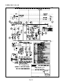
VI−Wiring Diagram and Sequence of Operation
A−HP29−090−2 Y, G, J, M
7
4
1
2
6
3
5
Page 20
B−HP29−090−3 Y, G, J, M
7
4
1
2
6
3
5
Page 21
SEQUENCE OF OPERATION HP29−090
1−
2−
3−
4−
5−
6−
7−
After each thermostat demand, time delay locks
out the circuit to compressor contactor coil and
defrost control for 5 + 2 minutes. At the end of the
time period, the time delay allows the compressor
contactor and defrost control to be energized
upon demand.
COOLING
Cooling demand energizes through terminal Y1 at the
indoor thermostat provided 5−minute time delay is sat
isfied.
Voltage passes through N.C. K8−1 to CMCI defrost
control. K6 set coil is enegized.
N.O. K6−1 latching relay contacts close, energizing L1
reversing valve.
K58 low ambient relay is energized. N.C. K58−1 con
tacts open eliminating S11 by−pass.
Voltage passes through S11 low pressure switch
(switch will close provided liquid line pressure rises to
275 + 10 psig.), energizing outdoor fan relay K10. N.O.
K10−1 contacts close, energizing outdoor fan B4. N.C.
K10−2 contacts open, de−energizing HR1 crankcase
heater.
Compressor contactor K1 is energized. N.O. K1−1
contacts close, energizing compressor B1.
"G" from indoor thermostat sends 24V through K8−2
N.C. contacts to "G1" energizing indoor blower.
HEATING
1 − Heating demand energizes through terminal W1 at the
indoor thermostat provided 5−minute time delay is sat
isfied.
2 − K8 transfer relay is energized. N.C. K8−1 contacts
open and N.O. contacts close, sending voltage to
CMCI defrost control. K6 re−set coil is energized.
3 − N.O. K6−1 latching relay contacts open, de−energizing
L1 reversing valve.
4 − K58 low ambient relay is de−energized. N.C. K58−1
contacts close, by−passing S11 low ambient switch.
5 − K10 outdoor fan relay is energized. N.O. K10−1 con
tacts close, energizing outdoor fan B4. N.C. K10−2
contacts open, de−energizing HR1 crankcase heater.
6 − Compressor contactor K1 is energized. N.O. K1−1
contacts close, energizing compressor B1.
7 − K8−2 N.O. contacts close sending 24V from "G1" ener
gizing indoor blower.
DEFROST MODE
7 − During heating operation, when outdoor coil drops be
low 35 + 4_ F, the defrost thermostat S6 closes. When
S6 closes, K4 defrost relay is energized. If defrost ther
mostat remains closed at the end of 30, 60, or 90 min
utes, defrost control energizes and defrost begins.
8 − When defrost control energizes, reversing valve L1
and indoor heat relay are energized. Outdoor fan is de−
energized.
9 − Defrost continues until 14 + 1 minutes have elapsed or
until S46 defrost pressure switch opens. When defrost
pressure switch opens to terminate defrost, the defrost
timer loses power and resets. Defrost timing is
stopped until the next call for defrost (when defrost
thermostat closes).
Page 22
C−HP29−120−2 Y, G, J, M
4
1
2
6
7
3
5
Page 23
D−HP29−120−3 Y, G, J, M
1
2
4
6
7
3
5
Page 24
SEQUENCE OF OPERATION HP29−120
1−
2−
3−
4−
5−
6−
7−
8−
1−
2−
After each thermostat demand, time delay locks
out the circuit to compressor contactor coil and
defrost control for 5 + 2 minutes. At the end of the
time period, the time delay allows the compressor
contactor and defrost control to be energized
upon demand.
COOLING
Cooling demand energizes through terminal Y1 at the
indoor thermostat.
Voltage passes through N.C. K8−1 to CMCI defrost
control. K6 set coil is energized.
N.O. K6−1 latching relay contacts close, energizing L1
reversing valve.
K58 low ambient relay is energized. N.C. K58−1 con
tacts open, eleminating the S11 and S41 by−pass.
Voltage passes through S11 low pressure switch,
(switch will close provided liquid line pressure rises to
275 + 10 psig.), energizing K10 outdoor fan relay 1.
N.O. K10−1 contacts close, energizing outdoor fan B4.
N.C. K10−2 contacts open de−energizing HR1 crank
case heater.
Voltage passes through S41 low ambient switch ener
gizing K68 outdoor fan relay 2. N.O. K68−1 contacts
close, energizing outdoor fan B5.
Compressor contactor K1 is energized. N.O. K1−1
contacts close, energizing compressor B1.
"G" from indoor thermostat sends 24V through K8−2
N.C. contacts to "G1" energizing indoor blower.
HEATING
Heating demand energizes through terminal W1 at the
indoor thermostat.
K8 transfer relay is energized. N.C. K8−1 contacts
open and N.O. contacts close, sending voltage to
CMCI defrost control. K6 set−coil is energized.
Page 25
3 − N.O. K6−1 latching relay contacts open, de−energizing
L1 reversing valve.
4 − K58 low ambient relay is de−energized. N.C. K58−1
contacts close by passing S11 low ambient switch and
S41 low ambient thermostat.
5 − K10 outdoor fan relay is energized. N.O. K10−1 con
tacts close, energizing outdoor fan B4. N.C. K10−2
contacts open, de−energizing HR1 crankcase heater.
6 − Voltage passes through S41 low ambient switch
(switch will close provided ambient is high enough),
energizing K68 outdoor fan relay 2. N.O. K68−1 con
tacts close energizing outdoor fan B5.
7 − Compressor contactor K1 is energized. N.O. K1−1
contacts close energizing compressor B1.
8 − K8−2 N.O. contacts close sending 24V from "G1" ener
gizing indoor blower.
DEFROST MODE
8 − During heating operation, when outdoor coil drops be
low 35 + 4_ F, defrost thermostats S6 (circuit 1) and
S124 (circuit 2) close. When S6 or S124 close, K4 de
frost relay is energized. If defrost thermostat remains
closed at the end of 30, 60, or 90 minutes, defrost con
trol energizes and defrost begins.
9 − When defrost control energizes, reversing valve L1
and indoor heat relay are energized. Outdoor fan is de−
energized.
10− Defrost continues until 14 + 1 minutes have elapsed,
or until S46 defrost pressure switch opens. When de
frost pressure switch opens to terminate defrost, the
defrost timer loses power and resets. Defrost timing is
stopped until the next call for defrost (when defrost
thermostat closes).
E− THERMOSTAT CONNECTIONS
Page 26
SERVICE NOTES
Page 27