1
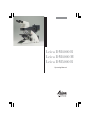
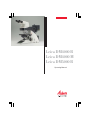
Leica DM4000 B Leica DM4000 M Leica DM5000 B Operating Manual 1 Published 2003 by: Leica Microsystems Wetzlar GmbH Ernst-Leitz-Straße D-35578 Wetzlar (Germany) Responsible for contents: Katja Peter, Karin Schwab Marketing CM, Compound Microscopy, Product Management In case of questions, please contact: 2 Phone +49(0)6441-292261 Fax +49(0)6441-292255 E-mail: [email protected] Leica DM4000 B Leica DM4000 M Leica DM5000 B Operating Manual 3 Copyrights Copyrights All rights to this documentation are held by Leica Microsystems Wetzlar GmbH. Reproduction of text or illustrations (in whole or in part) by print, photocopy, microfilm or other methods (including electronic systems) is not allowed without express written permission from Leica Microsystems Wetzlar GmbH. The term "Windows" can be used in the following text without further identification. It is a registered trademark of the Microsoft Corporation. Otherwise, no inference with regard to the free usability of product names may be drawn from the use of those names. The instructions contained in the following documentation reflect state-of-the-art techno-logy and knowledge standards. We have compiled the texts and illustrations as accurately as possible. Nevertheless, no liability of any kind may be assumed for the accuracy of this manual’s contents. Still, we are always grateful for comments and suggestions regarding potential mistakes within this documentation. The information in this manual is subject to modification at any time and without notification. 4 Contents Contents 1. Important Notes about this Manual ..... 7 2. Safety Notes .............................................. 2.1. General Safety Notes ............................... 2.2. Electrical Safety ........................................ 8 8 8 3. Overview of the Instrument .................... 10 4. Unpacking the Microscope .................... 14 5. 5.1 5.2 5.3 5.4 5.5 Assembling the Microscope .................. Stage ........................................................... Condenser .................................................. Tube and Eyepieces ................................. Objectives .................................................. Light Sources for the Transmitted Light Axis ............................. Light Sources for the Incident Light Axis .................................... Equipping the Incident Light filter turret ........................ Polarizer and Analyzer ............................. DIC Prisms .................................................. Optional Accessories ............................... Connection to the Power Supply ............ Connection to the CTR5000 Electronics Box ......................... 5.6 5.7 5.8 5.9 5.10 5.11 5.12 16 17 18 19 19 20 21 26 27 28 29 30 6. 6.1 6.2 6.3 Startup ........................................................ Functional Principle .................................. Switching on the Microscope ................ The Display (Leica DM4000 B/DM4000 M) ................. 6.4 The Function Keys .................................... 6.5 Köhler Illumination .................................... 6.6. Checking Phase Contrast Rings ............. 6.7 Adjusting the Light Sources .................... 7. 7.1 7.2 7.3 7.4 48 7.5 7.6 7.7 7.8 7.9 8. 8.1 30 31 31 34 35 36 37 39 40 Operation ................................................... Switching on the Microscope ................ Stages and Specimen Displacement .... Focusing ..................................................... Tubes ........................................................... 46 46 46 47 Eyepieces ................................................... Objectives .................................................. Magnification Changer ............................ Light Sources ............................................. Aperture Diaphragm and Field Diaphragm ........................................ 49 50 51 52 Imaging Procedure for Leica DM4000 B/Leica DM5000 B ......... Transmitted Light ...................................... 8.1.1 Bright Field ...................................... 8.1.2 Phase Contrast ............................... 8.1.3 Dark Field ......................................... 8.1.4 Polarization ..................................... 8.1.5 Differential Interference Contrast .................... 52 53 53 53 53 54 55 56 5 Contents 8.2 Fluorescence ............................................. 9. Imaging Procedure for Leica DM4000 M ....................................... 9.1 Incident Light ............................................. 9.1.1 Bright Field ...................................... 9.1.2 Dark Field ......................................... 9.1.3 Polarization ..................................... 9.1.4 Interference Contrast .................... 9.2 Transmitted Light ...................................... 9.2.1 Bright Field ...................................... 57 58 58 58 58 59 60 60 60 10. Trouble Shooting ...................................... 61 11. 11.1 11.2 11.3 6 Care of the Microscope ........................... Dust Cover .................................................. Cleaning ...................................................... Handling Acids and Bases ...................... 64 64 64 65 12. Essential Wear and Spare Parts ............................. 66 13. Abbreviations and Pictograms .............. 67 14. Index ........................................................... 68 15. EU Declaration of Conformity ................ 69 1. Important Notes about this Manual 1. Important Notes about this Manual Caution! This operating manual is an essential component of the microscope, and must be read carefully before the microscope is put into operation or used. This operating manual contains important instructions and information for the operational safety and maintenance of the microscope and accessories. Therefore, it must be kept and taken care of. Text symbols and their meanings: (1.2) Numbers in parentheses, such as "(1.2)", correspond to illustrations (in the example, Figure 1, Item 2). → p. 20 Numbers with pointer arrows (for example → p.20), point to a certain page of this manual. Special safety instructions are indicated with the triangle symbol shown here, and have a gray background. ! Caution! The microscope and accessories can be damaged when operated incorrectly. Explanatory note. * Item not contained in all configurations. 7 2. Safety Notes 2. Safety Notes 2.1 General Safety Notes 2.2 Electrical Safety This safety class 1 device is constructed and tested in accordance with EN 61010-1/IEC 1010-1, safety regulations for electrical measuring, control, and laboratory devices. General specifications Caution! In order to maintain this condition and to ensure safe operation, the user must follow the instructions and warnings contained in this operating manual. Caution! The devices and accessories described in this operating manual have been tested for safety and potential hazards. The responsible Leica affiliate or the main plant in Wetzlar must be consulted whenever the device is altered, modified or used in conjunction with non-Leica components that are outside of the scope of this manual. Unauthorized alterations to the device or noncompliant use shall void all rights to any warranty claims! 8 Leica CTR5000 electronics box (for DM5000 B) For indoor use only. Supply voltage: Frequency: Power input: Fuses: Ambient temperature: Relative humidity: Overvoltage category: Pollution degree: 90-250 V~ 50-60 Hz max. 290 VA T6,3 A (IEC 60127-2/3) 15-35°C max. 80% to 30°C II 2 Microscope For indoor use only. Supply voltage: Frequency: Power input: DM4000 DM5000 Fuses: DM4000 DM5000 Ambient temperature: Relative humidity: Overvoltage category: Pollution degree: 90-250 V~ 50-60 Hz max. 180 VA max. 290 VA T6,3 A (IEC 60127-2/3) See CTR5000 15-35°C max. 80% to 30°C II 2 2. Safety Notes Supply unit ebq 100 For indoor use only. Supply voltage: Frequency: Power input: Fuses: Ambient temperature: Relative humidity: Overvoltage category: Pollution degree: (see enclosed manual) Caution! 90-250 V~ 50-60 Hz max. 155 VA 2xT2A (IEC 127) 15-35°C max. 80% to 30°C II 2 Never use any fuses as replacements other than those of the types and the current ratings listed here. Using patched fuses or bridging the fuse holder is not permitted. Caution! The microscope’s electrical accessory components are not protected against water. Water can cause electric shock. Caution! The power plug may only be plugged into an outlet equipped with a grounding contact. Do not interfere with the grounding function by using an extension cord without a ground wire. Any interruption of the ground wire inside or outside of the device, or release of the ground wire connection, can cause the device to become hazardous. Intentional ground interruption is not permitted! Caution! Through connection to the grounding connection, ancillary equipment with its own and/or extra power supply may be brought to the same ground wire potential. For connections without a ground connector, Leica Service must be consulted. Caution! Protect the microscope from excessive temperature fluctuations. Such fluctuations can lead to the accumulation of condensation, which can damage the electrical and optical components. Ambient temperature: 15-35°C. Caution! Before exchanging the fuses or lamps, be absolutely certain to switch-off the main power switch and remove the power cable. 9 3. Overview of the Instrument 3. Overview of the Instrument Specification Leica DM4000 B / DM5000 B Leica DM4000 M Imaging Procedure • transmitted light: BF, DF, PH, Pol (DM5000 B also ICT) • incident light: fluorescence • transmitted BF, DF, PH light: ICT, Pol • incident light: BF, DF, ICR, Pol Transmitted Light Axis Incident Light Axis Z Pinion • automatic Illumination Manager (motorized aperture diaphragm and field diaphragm, motorized intensity control) • automatic Constant Color Intensity Control (CCIC) • motorized shutter • integrated into the stand • motorized 5x filter turret (DM5000 B 8x optional) • with FIM (Fluorescence Intensity Managemer) for decreasing light intensity in 5 stages • mechanical “Booster Lens” for increasing fluorescence intensity • motorized shutter • integrated into the stand • motorized 4x filter turret • automatic Illumination Manager • motorized shutter • manual Objective nosepiece • manual • absolute coded • 6x with M25 thread (DM5000 B: 7x; mot. DIC objective prism turret with 4 positions optional) • • • • X/Y Stage • manual • replaceable specimen stage • coaxial pinion length: 155 mm • manual • replaceable specimen stage • coaxial pinion length: 140 mm Tube 10 manual absolute encoded 6x with M32 thread slot for DIC prisms and Pol compensators (optional) • manual or motorized • optionally with two camera outputs 3. Overview of the Instrument Specification Condenser Magnification Changer Leica DM4000 B / DM5000 B Leica DM4000 M • motorized condenser head • motorized condenser turret for light rings, DF stop, DIC prisms • optional polarizer integrated and motorized • automatic Köhler Illumination • manual • absolute coded • 1x; 1.25x; 1.6x • manual • absolute coded • 1x; 1.5x; 2x Control Panels • • • • • Computer Interface • RS232C Software Tools • Leica DMControl for WindowsTM 2000, XP, NT; • with plugins for: • customitsation • DM Operation (remote control) • basic Image Viewer CTR5000 Electronics Box operating buttons for all motorized microscope functions additional variable function keys focusing knobs LC display DM5000 B with LeicaScreen (touchscreen) For Leica DM5000 B only: Separate control unit with power supply for 100W halogen lamp see p. 8 (electrical safety) 11 3. Overview of the Instrument 1 2 3 14 4 5 6 7 13 Fig. 1 1 2 3 4 5 6 7 12 12 11 10 9 8 Leica DM4000 M left side of the stand with AET22 advanced ergotube Eyepiece Eyepiece tube Tube Objective nosepiece with objectives Specimen stage with specimen holder Condenser LC display 8 9 10 11 12 13 14 Function keys field diaphragm Transmitted light/incident light switch Function keys aperture diaphragm Function keys: Light intensity Focus dial with coarse and fine adjustment Variable function keys (factory pre-assigned) Lamp adjustment window 3. Overview of the Instrument 15 22 16 21 Fig. 2 15 16 17 18 19 20 21 22 20 19 18 17 Leica DM4000 B right side of the stand with Advanced Ergotube AET22 Lamp housing for incident light Lamp housing for transmitted light Transmitted light filter, optional Transmitted light filter, optional Variable function keys (factory pre-assigned) X/Y coaxial drive, height adjustable Focus fine adjustment Motorized filter cube exchanger 13 4. Unpacking the Microscope 4. Unpacking the Microscope The device is delivered in two boxes. The stand box contains the following components: • Stand with integrated incident light axis and objective nosepiece • Specimen stage with stage bracket The external ebq 100 supply unit* is delivered in separate packaging. For the Leica DM5000 B microscope: The CTR5000 electronics box is also delivered in separate packaging. First, carefully remove all components from the transportation and packaging materials. • Power cable and PC connecting cable • CD with Leica software package • Instructions and list of microscope default settings (“Identification Sheet”) The system box contains the microscope accessories: • Tube Note: Avoid touching the lens surfaces of the objectives. If fingerprints do appear on the glass surfaces, remove them with a soft leather or linen cloth. Even small traces of finger perspiration can damage the surfaces of optical surfaces in a short time. See the chapter, "Care of the microscope" → p. 64, for additional instructions. • Eyepieces • Objectives • Condenser • Lamp housings with accessories • Fitting tool • Depending on configuration, additional microscope accessories such as filter cubes, etc. 14 Caution! Do not yet connect the microscope and peripherals to the power supply at this point! 4. Unpacking the Microscope Installation location Transport Work with the microscope should be performed in a dust-free room, which is free of oil vapors and other chemical vapors, as well as extreme humidity. At the workplace, large temperature fluctuations, direct sunlight and vibrations should be avoided. These conditions can distort measurements and micrographic images. For shipping or transporting the microscope and its accessory components, the original packaging should be used. Allowable ambient conditions Temperature 15-35°C Relative humidity maximum 80% up to 30°C • Unscrew the objectives. Microscopes in warm and warm-damp climatic zones require special care in order to prevent the build up of fungus. See the chapter, "Care of the microscope" → p. 64, for additional instructions. • Remove the stage. As a precaution to prevent damage from vibrations, the following components should be disassembled and packaged separately: • Remove the condenser. • Remove the lamp housings. • Disassemble the burner of 106 z lamp housing. • Remove all moving or loose parts. Caution: Electrical components must be assembled at least 10 cm from the wall and away from flammable substances. 15 5. Assembly 5. Assembling the Microscope The microscope components are logically assembled in this order: • • • • • • • Stage Condenser Tube Eyepieces Objectives Light sources Filter cubes/reflectors* Only a few commonly used screwdrivers and keys are necessary for assembly, which are included in the delivery package. 16 When using intermediate systems and optical accessories, the sequence may vary. In this case, read Chapter, "5.10 Optional accessories" → p. 29 5. Assembly 5.1 Stage ! Caution: Before assembling the stage, make sure no objectives are installed! • From above, set the stage clamp onto the dovetail guide (4.2) and push the stage downwards until the upper end of the dovetail guide is tightly fastened to the upper end of the stage clamp. • Firmly tighten the stage clamp (4.1). • Place the specimen holder on the stage and fasten it with the two screws (3.1). • Using the condenser height adjuster (3.2), turn the condenser holder completely upwards, i.e. as close to the stage as possible. • Loosen the stage clamp (3.3) slightly. Fig. 3 Mechanical object stage 1 Locking screws for specimen holder 2 Condenser height adjuster 3 Stage clamp Note: For thicker specimens (Leica DM4000 M) the stage can be set to a correspondingly lower level. Fig. 4 Assembling the stage 1 Stage clamp 2 Dovetail guide 1 1 2 2 3 17 5. Assembly 5.2 Condenser • Using the condenser height adjuster (5.4), turn the condenser holder (5.1) completely downwards. • Unscrew the clamping screw for the condenser (5.3) far enough so that the condenser can be inserted from the front. Note: The condenser must be centered before using the microscope. → Köhler illumination p. 37. Fig. 6 Underside of condenser 1 Orientation pin 1 • From the front, insert the condenser into the condenser holder as far as it will go. On the underside of the condenser, there is an orientation pin (6.1), which must be located in the guiding notch (7.1). • Pull the condenser’s clamping screw (5.3) so that the condenser is locked in place. Fig. 7 Condenser holder 1 Guiding notch • Connect the condenser over the connection (8.1) with the stand. 1 Fig. 5 Condenser holder 1 Condenser holder 2 Condenser centering 3 Clamping screw for condenser 4 Condenser height adjuster Fig. 8 Condenser connector 1 Condenser cable socket 1 2 3 18 4 1 5. Assembly 5.3 Tube and Eyepieces The tube is mounted to the stand either directly or with the use of intermediate modules. It is fastened in place with the side clamping screw (9.1). Fig. 9 Fastening the tube 1 Clamping screw 1 • Loosen the clamping screw (9.1). • Insert the tube in the circular receptacle (dovetail ring). • Retighten the clamping screw (9.1). • Only for the MBDT motorized tube: Connect the tube to the stand with the connector socket (10.1). • The eyepieces are inserted into the eyepiece tubes on the tube. Fig. 10 Motorized tube connection 1 Connector socket 6.4 Objectives The receptacles on the objective turrets are numbered (Fig. 11). The individual objectives have already pre-assigned positions at the factory according to their configuration. A list of the exact objective positions is provided in shipment. (“Identification Sheet”) ! 1 Caution: Cover unoccupied threads on the turret with dust protector caps! Fig. 11 Objective turret with labeled objective receptacles 19 5. Assembly 5.5 Light Sources for the Transmitted Light Axis Caution: Fig. 12 Lamp housing 107/2 Releasing the fastening screw Be sure that the lamp housing is disconnected from the power supply. Unplug the power plug and the power supply during assembly. 107/2 Lamp Housing This lamp housing is used with a 12V 100W halogen lamp, which is already mounted. In case the lamp has to be removed: • Remove the fastener screw on the housing (Fig. 12). • Remove the housing by pulling it upwards. • Remove the lamp • Insert the new 12V 100W lamp (13.1) with dust cover straight into the socket until it stops. Be sure that the lamp is inserted straight. • Remove the lamp’s dust cover. Caution: Do not remove the lamp’s dust cover until you have installed the lamp. Avoid fingerprints on the lamp. Fig. 13 Lamp housing 107/2, opened 1 Mount with halogen lamp 2 Collector 1 2 Fig. 14 Rear side of stand 1 Incident light lamp housing receptacle 2 Transmitted light lamp housing receptacle 3 12 V 100 W connection for transmitted light (symbol: ) 4 12 V 100 W connection for incident light (symbol: ) • Replace the housing and fasten it in place using the fastening screw. • Place the lamp housing in the transmitted light lamp housing receptacle (14.2) and fasten it with the clamping screw on the side. • Connect the lamp housing to the power supplyfor transmitted light (symbol: ) (14.3). 20 1 2 3 4 5. Assembly 5.6 Light Sources for the Incident Light Axis Caution: During assembly, always unplug the power supply unit of the 106 z lamp housing from its socket. Never touch the glass parts of the burner with bare hands. This lamp housing is used with a 12V 100W halogen lamp or various gas discharge lamps. Inserting the 12V 100W halogen lamp into the 106 z lamp housing • Unscrew the fastening screws of the cover and lift up the cover (16.1). • Unscrew the fastening screws of the lamp mount (16.8) and pull out the mount (Fig. 17). Never look directly into the beam path (blinding hazard). During assembly work on xenon burners, always wear the supplied protective gloves and face protection (Fig. 15) (risk of explosion). 106 z lamp housing Fig. 16 106 z lamp housing (on the side, open) 1 Cover raised 2 Collector 3 12 V 100 W lamp or gas discharge lamp in mount 4 Reflector (mirror) 5, 6, 7 Adjusting screw for x-y reflector 8 Fastening screw for lamp mount 9 Socket for contact plug Fig. 15 Protective gloves and mask 1 4 2 5 3 6 7 8 9 8 21 5. Assembly • Insert the lamp with the dust cover straight into the socket until it stops. • Place the lamp housing in the incident light lamp housing receptacle (18.1) and fasten it with the clamping screw on the side. • Remove the dust cover. • Reinsert the lamp mount and retighten the fastening screw (16.8). • Connect the lamp housing to the power supply for incident light (symbol ) (18.4). Caution: Do not remove the lamp’s dust cover until after you have installed the lamp. Be certain to avoid getting fingerprints on the lamp. • Close the lamp housing and retighten the fastening screws. Fig. 17 Lamp mount with 12 V 100 W halogen lamp Fig. 18 Rear side of stand 1 Incident light lamp housing receptacle 2 Transmitted light lamp housing receptacle 3 12 V 100 W connection for transmitted light (symbol: ) 4 12 V 100 W connection for incident light (symbol: ) 1 2 22 3 4 5. Assembly Inserting the gas discharge lamps (Hg and Xe) into the 106z lamp housing Hg and Xe lamps are powered by the separate ebq 100 supply unit. Read the separate instruction manual provided with this supply unit. The following gas discharge lamps may be used and require different lamp mounts (Fig. 19): Type Typical bulb life* 50 W high-pressure mercury burner (alternating current) 100 W high-pressure mercury burner (direct current, stabilized/not stabilized 100 W high-pressure mercury burner (direct current, stabilized/not stabilized, type 103 W/2) 75 W High-pressure xenon burner (direct current, stabilized) 100 hrs. 200 hrs. 300 hrs. 400 hrs. * Please regard the data sheets of the burners. 23 5. Assembly • To open the 106 z lamp housing, unscrew the fastening screws on the cover. Caution: • Remove the transport anchorage (red plastic rod in place of the burner) in the lamp mount. To do so, remove the lower clamp (19.1). Pull up the cooling element (19.3) and turn it to the side. Detach the lower clamp system (19.2) and remove the transport anchorage. Hg 50 burner: After installation, the labeling must be upright. If a glass melt nipple is present (19a.4), position it by turning the burner so that the nipple does not come in the way of the beam path later, but instead is positioned sideways. • Install the burner in mirror image fashion. Xe 75 burner: Remove the burner’s dust cover (19b.5) after you have installed the burner. Fig. 19 a-d Lamp mounts for gas discharge lamps 1 Upper clamping system, 2 Lower clamping system, 3 Cooling element 4 Nipple of the mercury 50 burner, 5 Dust cover of the mercury 75 burner Hg 50 a 3 Xe 75 1 1 2 2 Hg 100 c 3 Hg 100 Stab. 1 2 2 24 b 5 4 1 3 3 d 5. Assembly • Insert the lamp mount, with the burner installed, into the lamp housing and tighten it with the screws (20.8). • Put the lid down again. Plug in the contact plug as far as it goes and retighten the screws. • Place the lamp housing in the incident light lamp housing receptacle (21.1) and fasten it with the clamping screw on the side. • Connect the lamp housing to the power supply (22.1). Fig. 20 106 z lamp housing (on the side, open) 1 Cover raised 2 Collector 3 12 V 100 W lamp or gas discharge lamp in mount 4 Reflector (mirror) 5, 6, 7 Adjusting screw for x-y reflector 8 Fastening screw for lamp mount 9 Socket for contact plug 1 4 2 5 3 6 7 Fig. 21 Rear side of stand 1 Incident light lamp housing receptacle 2 Transmitted light lamp housing receptacle 3 12 V 100 W connection for transmitted light (symbol: ) 4 12 V 100 W connection for incident light (symbol: ) 8 9 8 Fig. 22 Rear side of the ebq 100 supply unit 1 Lamp connection 1 1 2 3 4 25 5. Assembly 5.7 Equipping the Incident Light filter turret The receptacles on the turret are numbered. According to your equipment, the individual filter and/or reflector cubes have already preassigned positions. A list is provided along with your shipment (“Identification Sheet”). Fig. 23 Filter cube front side Fig. 24 Filter cube back side Insert the filter and reflector cubes in the following manner: • Equip the incident light turret only when the microscope is switched off. • Remove the face plate from the upper part of the microscope (Fig. 25). Turn the turret in any direction until the locking pin engages. Fig. 25 Removing the front panel 1 Filter receptacle 2 Retention pin 3 Front panel • Insert the filter or reflector cube into the mounting in front of you according to the identification sheet provided. To do so, place the filter or reflector cube on the right side and press it to the left into the mounting (Fig. 26). 1 2 3 • Push the retention pin (25.2) and continue to turn the filter turret until you reach the next locking position. • Again make sure that the turret engages (retention pin unlocks) and insert the next filter and/or reflector cube as described above. • When all filters and reflector cubes have been inserted, close the front cover plate again. 5.8 Polarizer and Analyzer 26 Fig. 26 Inserting the filter or reflector cubes 1 Mounting 1 1 5. Assembly ICT/P transmitted light polarizer • Using the left clamping screw, fasten the ICT/P transmitted light polarizer to the underside of the condenser holder (Fig. 27). Fig. 27 Assembly of the ICT/P transmitted light polarizer 1 Clamping screw • Make sure that the red index point on the front of the polarizer is aligned with 0. • If necessary, insert the compensators (λ- and λ/4 plates) into the polarizer’s receptacle (Fig. 28). 1 Fig. 28 Inserting the compensators Incident light polarizers: R/P polarizer, rotating polarizer L/ICR, R/ICR polarizer • Remove the plug cap on the right side of the incident light axis (Fig. 29). Fig. 29 Inserting the polarizer 1 The plug cap is replaced with the polarizer. • Insert the polarizer into the receptacle until it latches in place. Motorized polarizer 1 • A motorized polarizer is already installed and ready for operation in the DIC condenser. Transmitted light and incident light analyzer 27 5. Assembly • Remove the plug cap on the left side of the stand. • Insert the polarizer into the receptacle until it latches in place (Fig. 30). Motorized analyzer • Insert the analyzer cube as described in section 5.7 "Equipping the Incident Light filter turret" → p. 26, in the corresponding position on the filter turret. See the list provided (“identification Sheet”) for the correct position. 6.9 DIC Prisms Fig. 30 Inserting the analyzer 1 The plug cap is replaced with the analyzer. • Insert the objective prism into the tube slot (Fig. 31.1). The code letter must match the code letter on the objective. • With the microscope Leica DM5000 B the DIC objective prisms are already mounted in the DIC turret above the objective revolving nosepiece(Fig. 68). 5.10 Optional Accessories Fig. 31 Inserting the objective prism slide 1 Objective prism slide 1 1 28 5. Assembly Ergomodule • Remove the clamping ring from the filter slide. For raising the eye level of the tube opening, the ergomodule may be used. It is fastened in place with the side clamping screw. • Insert the Manager. Booster Lens or Excitation • Push the cover back. • Insert the clamping ring. Mirror Housing • Place the mirror housing directly onto the lamp housing receptacle on the back of the stand and attach it using the side clamping screw. • Place the lamp housing onto the mirror housing and fasten it using the corresponding clamping screw on the side. • Insert the filter slide into the front receptacle on the right side of the stand (32.1, 33.1). • Using two filter sliders, the Excitation Manager can be inserted into the back receptacle. 5.11 Connection to the Power Supply Booster Lens / Excitation Manager Fig. 32 1 Insert of Booster Lens Fig. 33 1 Insert of Excitation Manager 1 1 29 5. Assembly After completing the assembly work, connect the stand to the power supply using the power cable (Fig. 34.2). 5.12 Connection to the CTR5000 Electronics Box Fig. 34 Rear side of stand Leica DM4000 B/M 1 Power switch 2 Power supply Only for the Leica DM5000 B: • Connect the microscope (36.1) to the "Microscope" jack (35.1) on the rear of the electronics box. Use the cable with the 25-pin plug. • Connect the electronics box to the power supply using the power cable (35.2). 1 2 Fig. 35 Rear side of electronics box CTR5000 1 Microscope connection 2 Power supply Fig. 36 Rear side of stand Leica DM5000 B 1 Connection to the CTR5000 electronics box 1 1 2 30 2 6. Startup 6. Startup 6.1 Functional Principle The microscope’s most important functions may be easily accessed using function keys. • The microscope may be switched between various contrast processes by pressing a single button. • The microscope recognizes the objective chosen and the respective contrast process. Therefore, the values for intensity (INT), aperture diaphragm (AP) and field diaphragm (FD) are always set correctly. • The values for INT, AP and FD can be changed individually. This overwrites the previous setting. Actual settings are stored automatically. • The specifications for INT, AP and FD always relate to the currently activated light axis (transmitted light or incident light). • In addition to the preset function keys for INT, AP and FD, there are also variable function keys. Variable function keys: • These function keys are assigned logical functions before delivery(see “Identification Sheet”) • These functions can be reprogrammed according to your individual wishes. Note: (Reset-Function) The microscope can be reset to the default functions programmed at the factory: • When the microscope is switched off, press all 3 variable function keys on the left stand section. • Switch on the stand. • Hold the keys pressed down until initialization is complete. • The standard information is shown in the display. • Switch off the instrument and switch it on again. The settings are stored now. 6.2 Switching on the Microscope • First, swivel the objective with the least magnification into position. 31 6. Startup Possible Assignments for the Function Keys For Leica DM4000 B/DM5000 B: Function key Meaning BF PH ICT DF POL CHANGE TL | Bright field (Transmitted light) Phase contrast (Transmitted light) Interference contrast (Transmitted light) Dark field (Transmitted light) Polarization (Transmitted light) Switch through all transmitted light processes INT INT AP AP FD FD ↑ ↓ ↑ ↓ ↑ ↓ Increase brightness (transmitted light) Reduce brightness (transmitted light) Open aperture diaphragm (transmitted light) Close aperture diaphragm (transmitted light) Open field diaphragm (transmitted light) Close field diaphragm (transmitted light) SHUTTER TL Open/close transmitted light shutter FLUO CUBE 1 CHANGE CUBE CHANGE CUBE SHUTTER FLUO Fluorescence (last filter cube) Select fluorescence cube at position 1 Switch through fluorescence cubes in clockwise fashion Switch through fluorescence cubes in counterclockwise fashion Open/close fluorescence shutter INT FLUO INT FLUO FD FLUO FD FLUO | | ↑ ↓ ↑ ↓ COMBI | CHANGE COMBI | 32 Increase brightness (fluorescence) Reduce brightness (fluorescence) Open field diaphragm (fluorescence) Open field diaphragm (fluorescence) Combination mode (PH / fluorescence or ICT / fluorescence) Switch through all combination modes 6. Startup For Leica DM4000 M: Function key Meaning BF ICR DF POL CHANGE RL | Bright field (Incident light) Interference contrast (Incident light) Dark field (Incident light) Polarization (Incident light) Switch through all incident light processes INT INT AP AP FD FD ↑ ↓ ↑ ↓ ↑ ↓ Increase brightness (incident light) Reduce brightness (incident light) Open aperture diaphragm (incident light) Close aperture diaphragm (incident light) Open field diaphragm (incident light) Close field diaphragm (incident light) SHUTTER RL Open/close incident light shutter FLUO CUBE 1 CHANGE FLUO Fluorescence (last filter cube) Select fluorescence cube at position 1 Switch through fluorescence cubes FOCUS FINDER Select smallest field diaphragm and switch back to original field diaphragm by pressing the key again BF TL INT ↑ INT ↓ AP ↑ AP ↓ FD ↑ FD ↓ Bright field (Transmitted light ) Increase brightness (transmitted light) Reduce brightness (transmitted light) Open aperture diaphragm (transmitted light) Close aperture diaphragm (transmitted light) Open field diaphragm (transmitted light) Close field diaphragm (transmitted light) COMBI | Combination process (BF and BF TL) 33 6. Startup • Switch-on the microscope at the power switch (34.1,36.1). All motorized microscope components first undergo an initialization phase. After initialization is complete, the display on the stand shows the current microscope setting (Fig. 37). After turning on the gas discharge lamps, the burner must be immediately adjusted. Therefore, do not turn on the power supply unit yet. First, work in transmitted light in order to familiarize yourself with the microscope’s controls. 6.3 The Display (Leica DM4000 B/DM4000 M) The microscopic components such as diaphragms, condenser, light and phase rings are already pre-centered in the factory. However, re-centering may be necessary due to transportation and assembly. Before proceeding with the necessary steps, first familiarize yourself with the stand’s display and control panel. Caution: Fig. 37 34 Display after initialization 6. Startup The display shows the current microscope settings. The display depends on the microscope’s configuration. In the first column, corresponding pictograms indicate the type of information: contrast method, magnification, light intensity, diaphragms, light splitting for photo tubes. Please see the abbreviation index for a list of abbreviations and pictograms used → p. 67. Light Intensity The actual brightness setting is graphically depicted by a beam. Additionally, the light intensity is indicated in 20 (coarse adjustment) or in 255 (fine adjustment) increments → p. 52. Diaphragms Contrast Method In the first row, you find an indication of the active light axis (transmitted light or incident light) of the current contrast method and the current filter cube. The shutter status is displayed for the transmitted light or incident light shutter: Transmitted light shutter open ↑ ↑ ↓ The values for the field diaphragm (FD) and the aperture diaphragm (AP) are indicated numerically. The field diaphragm may be either round or rectangular. Accordingly, the FD designation is set in parentheses or in brackets: (FD) or [FD]. Note: When using a digital camera, rectangular field diaphragms are recommended. Transmitted light shutter closed Incident light shutter open Incident light shutter closed ↓ Magnification + The current objective magnification, sometimes followed by the re-magnification of the magnification changer, appears along with the total magnification: Σ = Objective x Re-magnification x Eyepiece 6.4 The Function Keys Beam splitting If a motorized tube is used, the light splitting between ocular (Eye) and photo output (Docu) is indicated in %. Note: The display may flash after the initialization phase or even during microscopy session. This always occurs when the contrast method selected can not be performed with the actual microscopic settings. For example, an objective may be swiveled in that is not suited to the contrast method chosen. Then check your settings. 35 6. Startup There is a row of function keys both on the right and left side of the stand. Some of these keys are defined, and some of them are variable. The variable function keys have various meanings depending on the microscope configuration. Defined Function Keys on the left side of the stand The TL/IL key (38.1) switches between incident light and transmitted light. The last contrast method used is restored. The INT (38.3) keys adjust the light intensity individually. Settings can be made either in large or small increments. Pushing both INT buttons at the same time switches between coarse and fine setting. The display indicator changes accordingly → p. 52. The AP (38.4) keys for the aperture diaphragm and FD (38.2) for the field diaphragm are used to set each diaphragm. The optimal values are automatically preset when selecting the contrast method. Fig. 38 Defined Function Keys 1 Transmitted light/incident light 2 Field diaphragm 3 Light Intensity 4 Aperture diaphragm 3 2 4 1 36 Variable function keys: A factory preset is performed which fits your microscope configuration. The function keys are labeled accordingly, and a separate description of the key occupation accompanies the microscope (“Identification Sheet”). Abbreations are listed on p.32f. 6.5 Köhler Illumination For each objective, optimal values for the aperture diaphragm and the field diaphragm are already set. The condenser is also already adjusted in the factory. 6. Startup However, depending on how the condenser is disassembled and reassembled, it may be necessary to re-adjust the condenser in some cases. Therefore, check the condenser centering. The following procedure is provided for the transmitted light-bright field illumination. • Select an objective magnification (10x-40x). with moderate • Activate the transmitted light axis by pushing the TL/IL button (38.1). "TL" appears in the first line of the display. • Choose "bright field" as the contrast method by pressing the BF (one of the variable function keys, behind the focus dials). "TL BF" appears in the first line of the display. • Insert the specimen in the stage’s specimen holder (39.3). • Focus on the specimen. The focus wheel on the left side of the stage allows focus adjustment in large and small increments. On the right side of the stage, there is also a focus wheel for fine focus adjustment. • Set the light intensity using the INT keys (38.3). • Close the field diaphragm with the FD function key (38.2) until the edge of the diaphragm appears in the specimen plane. • Using the condenser height adjuster (39.4), adjust the condenser until the edge of the field diaphragm appears in sharp relief. • If the image does not appear in the middle of the field of view (41c), the condenser must be moved into the middle of the field of view with the help of the two leveling screws (40.1). Fig. 39 Stage with specimen holder 1 Object motion (X direction) 2 Object motion (Y direction) 3 Specimen holder 4 Condenser height adjuster 3 2 1 4 37 6. Startup • Open the field diaphragm just enough for it to disappear from the field of view (41d). Do not adjust the aperture diaphragm. The aperture diaphragm is already set optimally for each objective. 6.6. Checking Phase Contrast Rings Caution: Fig. 40 Condenser centering 1 Centering bolts 1 38 Fig. 41 Köhler Illumination a Field diaphragm not focused, not centered b Field diaphragm focused, but not centered c Field diaphragm focused and centered Diameter is too small, however d Field diameter (light) = Field diameter (view) (Köhler Illumination) 1 A B C D 6. Startup If your microscope is equipped for the use of phase contrast, the light rings that fit the objectives are built into the condenser. The light rings are already leveled in the factory. However, the leveling should be rechecked. • In the place of an eyepiece, insert the focusing telescope (Fig. 42) into the observation tube. • Swivel in the phase contrast objective with the least magnification. Note: Every objective is assigned its own light ring in the condenser disc. Therefore, a check must be performed for each objective. When swiveling in a suitable objective for phase contrast, the corresponding light ring is set automatically. • Press the BF (Bright Field) button (one of the variable function keys, behind the focus dials). • Focus the ring structure (43a) by slightly loosening the clamping ring (42.2) and moving the eyelens (42.1). • Retighten the clamping ring. • Press the PH (Phase Contrast) button. The ring diaphragm in the condenser is pivoted in. • If the light ring and the phase ring are not shown as arranged in Fig. 43c, the light ring must be leveled. Fig. 42 Focusing telescope 1 Adjustable eyelens 2 Clamping ring for fixing the focus position 1 Fig. 43 Phase contrast centering procedure PH=phase contrast ring, LR=light ring a Condenser in bright field (BF) position b Condenser in phase contrast (PH) position Light ring (LR) not centered c Light ring and phase ring centered A B C 2 PH LR 39 6. Startup • Insert the centering key through the corresponding openings (44.1) in the condenser holder. • Turn the centering screws until the dark ring (phase ring in the objective) is congruent with the slightly narrower bright ring (light ring in condenser) (43 c). • Repeat the process for all other phase contrast objectives. • Remove the centering keys after the centering procedure. Note: During change of objectives the centering keys must not remain in the openings of the condenser. 6.7 Adjusting the Light Sources Transmitted Light Axis (TL) with 107/2 Lamp housing 40 Fig. 44 Light ring centering 1 Clamping screw 1 6. Startup The 107/2 lamp housing with 12 V 100 W halogen lamp has a defined presetting. The lamp need not to be centered. When switching to the BF or Smith reflectors, there is a danger of being glared! • When a supply unit is used, it is turned on first. For the 106 z lamp housing, the direct filament image (for halogen lamps) or direct arc image (for gas discharge lamps), and its mirror image are focused separately and adjusted to each other. • Activate the incident light axis using the TL/IL function key. FLUO (Leica DM4000 B/ DM5000 B) or IL (Leica DM4000 M) appears in the display. On the left side of the microscope, there is an adjustment window (1.14, p. 12) for mapping the light source. • Insert the reflector for lamp adjustment (Fig. 45) into the filter turret in place of a filter cube. (See → p. 26). Note the name of the exchanged filter cube. While observing the light source in the adjustment window, the lamp is adjusted as follows: Incident light axis (IL) with 106 z lamp housing Centering the 12 V 100 W Halogen Lamp • Turn the reflector into the light path. The reflector has reached the correct position when the name of the exchanged filter cube is shown in the upper right of the display. Caution: Never look directly into the light path! Fig. 46 106 z lamp housing 1 Lamp height adjustment 2,4 Mirror image height and side adjustment 3 Focusing the reflector 5 Lamp side adjustment 6 Collector (focusing of the lamp image) 5 Fig. 45 1 6 Reflector cube for lamp adjustment (similar to illustration) 2 3 4 41 6. Startup • In the adjustment window, you see the direct filament image and the mirror image, which in most cases are shifted together. Fig. 47 Direct lamp filament image focused, but not centered (in reality, the image is less focused) Fig. 48 Direct lamp filament image in target position (in reality, the image is less focused) Fig. 49 Direct lamp filament image and mirror image in target position (in reality, the image is less focused) • Focus the direct filament image with the collector (46.6). • Use the adjusting buttons on the rear side of the lamp housing (46.2, 46.4) to pivot the lamp filament’s mirror image to the side or completely out of the beam path. The lamp filament’s focused image remains visible (Fig. 47). • Adjust the direct filament image using the adjusting knobs (46.1) and (46.5) so that the centering surface is halfway covered (Fig. 48). • Then pivot the lamp filament’s mirror image with the adjusting knobs (46.2 and 4), and focus it using the reflector (46.3). • Align the mirror image symmetrically to the filament image (Fig. 49). To do so, use the adjusting knobs (46.2) and (46.4) again. • Defocus the image with the collector head (46.6) until the filament image and mirror image are no longer recognizable and the image is uniformly illuminated. • Exchange the reflector cube for lamp adjustment for the original filter cube. Note: Turn off the microscope before exchanging the reflector cube. Centering the Hg 50 W mercury lamp • In the adjustment window, you see the direct arc image and the mirror image, which in most cases are shifted together. 42 6. Startup Fig. 50 Direct arc image focused but decentered (in reality, the image is less focused) Fig. 51 Direct arc image in target position (in reality, the image is less focused) Fig. 52 Direct arc image and mirror image in target position (in reality, the image is less focused) • Focus the direct image with the collector (46.6). • Use the adjusting buttons on the rear side of the lamp housing (46.2,46.4) to pivot the arc’s mirror image to the side or completely out of the beam path. The lamp filament’s focused image remains visible (Fig. 50). • Use the adjusting buttons (46.1) and (46.5) to place the direct arc image right or left on an imaginary center line of the centering plane (Fig. 51). • Then pivot the arc’s mirror image with the adjusting knobs (46.2 and 4) and focus it using the reflector (46.3). • Use the adjusting knobs (46.2 and 4) to orient the mirror image symmetrically to the direct image (Fig. 52). • Defocus the image with the collector knob (46.6) until the arc image and mirror image are no longer recognizable and the image is uniformly illuminated. • Exchange the reflector cube for lamp adjustment for the original filter cube. Centering the Hg 100 W and Xe 75 W mercury lamps • In the adjustment window, you see the direct arc image and the mirror image, which in most cases are shifted together. 43 6. Startup Fig. 53 Direct arc image focused but not centered (in reality, the image is less focused) Fig. 54 Direct arc image in target position (in reality, the image is less focused) Fig. 55 Direct arc image and mirror image in target position (in reality, the image is less focused) • Focus the direct image with the collector (46.6). • Use the adjusting buttons to pivot the arc’s mirror image on the rear side of the lamp housing (46.2,46.4) to the side or completely out of the beam path. The arc’s focused image remains visible (Fig. 53). • Use the adjusting buttons (46.1 and 5) to place the direct arc image in the middle of the centering plane, whereby the bright tip of the arc, the focal spot, should lie slightly outside the center (Fig. 54). • Then pivot the arc’s mirror image with the adjusting knobs (46.2) and (46.4) and focus it using the reflector (46.3). • Use the adjusting knobs (46.2 and 4) to orient the mirror image symmetrically to the direct image (Fig. 55). The V-shaped irradiation of the direct image and mirror image arcs can be superimposed. Caution: The bright tips of the arcs, the focal spots, must never be projected onto each other, as this results in a danger of explosion by overheating. 44 6. Startup In older lamps, the structure of the arc is no longer clearly recognizable. The image is then more like that of a HG 50 lamp. The image and mirror image can no longer be superimposed exactly. In this case, align both images. • Using the collector, defocus the image with the knob (46.6) until the arc image and mirror image are no longer recognizable and the image is uniformly illuminated. • Exchange the reflector cube for lamp adjustment for the original filter cube. Note: Turn off the microscope before exchanging the reflector cube. 45 7. Operation 7. Operation 7.1 Switching on the Microscope When using a gas discharge lamp, the ebq 100 external supply unit must be turned on separately (56.1). Then switch-on the microscope at the power switch. All motorized microscope components first undergo an initialization phase. After the initialization is complete, the display on the stand (Fig. 57) shows the current microscope setting. 7.2 Stages and Specimen Displacement Lengthening the coaxial pinion • For lengthening, pull the lower grip (58.2) downwards. Repeat with the upper grip (58.1). Torque adjustment The torque is already optimally set at the factory, however, it can be individually adjusted using two knurled rings (58.3, 58.4). Fig. 56 Front view of the ebq 100 supply unit 1 Power switch 2 Lamp status Fig. 58 Revolving object stage 1 Object motion (Y direction) 2 Object motion (X direction) 3 Torque adjustment (Y direction) 4 Torque adjustment (X direction) 5 Focus dial for fine focusing 1 Fig. 57 2 Display after initialization 3 5 1 2 4 46 7. Operation Rotating the Stage 7.3 Focusing The swiveling range of the rotating stages is 0°- 110°. There is a focus dial on the left side of the stage for coarse and fine focus adjustment (Fig. 59). • In order to revolve the stage, loosen the fastening screw (59.1). On the right side of the stand, there is also a focus dial, which is used exclusively for fine focusing (58.4). The special design of this dial makes it possible to simultaneously grasp the coaxial drive with your hand while operating the fine drive with one finger. • Bring the table into the desired position. • Retighten the fastening screw. Fig. 59 Revolving object stage 1 Clamping screw 2 Fine focusing 3 Coarse focusing 1 2 3 47 7. Operation 7.4 Tubes Adjusting the Viewing Angle • For the AET22 and EDT22 ergotubes, the viewing angle can be adjusted by tilting the binocular viewer in the range of 5° - 32° (Fig. 61). Note: Close any unused tube openings, as otherwise stray light can interfere with observation. Note: Make sure that the connector cable is plugged in on the MBDT25+ motorized tube (60.1). Adjusting the Eyepiece Extension to the Arm Length • With the AET22 tube, the eyepieces can be extended up to 30 mm (Fig. 61). Adjusting the Viewing Distance • Adjust the viewing distance of the eyepieces so that a congruent total image is seen (Fig. 60). Fig. 60 Tube setting ↔ Personal eyebase settings 1 Motorized tube connection 1 48 Fig. 61 ↔ With AET22 tube individual adjustments 7. Operation Beam Splitting in Photo Tubes 7.5 Eyepieces EDT22 tube: The beam splitting between the observation and documentation outputs has a definite presetting (50:50). BDT25+ tube: The beam splitting is set manually by pulling out a control bar. Control Bar VIS 50/50 PHOTO Observation 100 % 150 % 110 % Photo 0% 50 % 100 % MBDT25+ tube: This tube is similar to the documentation tube BDT25+, but it is motorized. The control positions are selected using a variable function key on the stand. Note: The eyepiece’s aperture protector must be removed,or at least folded back, during microscopy while wearing eyeglasses. Eyeglasses with multifocal lenses (bifocals and smooth view glasses) must be removed while operating the microscope. • For the adjustable tubes with documentation output, choose the 100% position. Eyepieces with Inlaid Reticle • Focus the reticle by adjusting the eyelens. • Focus on the object through this eyepiece. HC L 2TU tube: The beam splitting is set manually by pulling out a control bar. Control Bar VIS PHOTO Observation 100 % 110 % Photo 0% 100 % • Then, close that eye and focus on the specimen by adjusting only the second ocular. Correction for Vision Problems • With your right eye, look through the right eyepiece and bring the specimen into sharp focus. Fig. 62 BDT25+ tube with digital camera 1 Control bar • Then, with your left eye, view the same specimen and rotate the left eyepiece tube until the object is brought into sharp focus. Do not use the focus dial. 1 49 7. Operation 7.6 Objectives The objective must be moved manually into the light path. Be sure that the nosepiece turret locks into place. The objective’s position in the turret is factoryset and must be adhered to while screwing in the objectives (see Objective Assembly → p. 19) When you rotate the objective into position, the microscope automatically recognizes: • the selected contrast method • the optimal settings for field and aperture diaphragm • the optimal condenser setting The objective magnification and the total magnification appear in the display → p. 35. 50 • Start with a small level of magnification. Then switch to the next higher objective. • For immersion objectives use the appropriate immersion medium. OIL: only use optical immersion oil according to DIN/ISO standards. Cleaning → p. 65. W: Water immersion. IMM: Universal objective for water, glycerol, oil immersion. Caution! Follow safety instructions for immersion oil! 7. Operation For lockable immersion objectives: 7.7 Magnification Changer • Lock these by pushing the front part upwards until it stops (approx. 2 mm). Optionally, a coded magnification changer can be used, which is manually operated. On the knurled ring, the following magnification factors can be set: For objectives with corrective mounts: • Turn the knurl to adjust the objective to the thickness of the cover glass. Immersion objective (released) ↔ Fig. 63 B Stand 1x 1.25x 1.6x M Stand 1x 1.5x 2x The selected factor is indicated in the display and included in the total magnification. Fig. 64 Immersion objective (locked) ↔ • Then, after a gentle turning motion to the right, the objective is locked (Fig. 64). 51 7. Operation 7.8 Light Sources 7.9 Aperture Diaphragm and Field Diaphragm • The brightness is set using the function keys (65.5). Then, the INT function keys are assigned to the currently active axis for transmitted light (TL) or incident light (IL). Both diaphragms are already factory-set to the optimum setting for the current objective. • For TL and IL: Settings can be made either in large or small increments. Pushing both INT buttons simultaneously switches between coarse and fine setting. The display indicator changes accordingly. 0-20 ====== Coarse adjustment: 0-255 Fine adjustment: ---------- • For Fluo: The brightness is set in 5 fixed steps (FIM): 100% / 55% / 35% / 20% / 10% Fig. 645 Control panel 1 Variable function keys 2 Aperture diaphragm 3 Transmitted light/incident light 4 Field diaphragm 5 Light intensity 1 52 2 3 4 5 • The AP (65.2) keys for the aperture diaphragm and the FD keys (65.4) for the field diaphragm may be used to change each diaphragm’s setting at any time. Then, the function keys are assigned to the currently active axis for transmitted light (TL) or incident light (IL). Caution: When doing so, old values are overwritten and the new values are stored! Caution: While using PH or DF the aperture diaphragm is completely opened and locked. 8. Imaging Procedure for Leica DM4000 B/DM5000 B 8. Imaging Procedure for Leica DM4000 B/ Leica DM5000 B 8.1 Transmitted Light 8.1.1 Bright Field (TL) • Switch to the transmitted light axis (TL) by pushing the TL/IL button. • Select the BF (bright field) contrast method. Do so by pressing the BF variable key. Alternatively: Press the CHANGE TL | variable key. (For key occupation please see “Identification Sheet”.) The display indicates BF. • Insert a transmitted light specimen. • Rotate an appropriate objective into place. • Bring the image into focus using the focus dial and set the brightness using the INT function key. 8.1.2 Phase Contrast • Switch to the transmitted light axis (TL) by pushing the TL/IL button. • Select the PH contrast (phase contrast) method. Do so by pressing the PH variable key. Alternatively: Press the CHANGE TL | variable key. (For key occupation please see “Identification Sheet”.) The display indicates PH. • Insert a transmitted light specimen. • Rotate an appropriate objective into place. Objectives that are suitable for phase contrast are engraved with PH. • Bring the image into focus using the focus dial and set the brightness using the INT function key. 53 8. Imaging Procedure for Leica DM4000 B/DM5000 B 8.1.3 Dark Field (TL) Notes: • The microscope automatically selects the correct light ring in the condenser. • When selecting the phase contrast method, the aperture diaphragm is opened completely and may not be adjusted. To avoid errors in operation, the function keys for setting the aperture diaphragm (AP) are locked. • Switch to the transmitted light axis (TL) by pushing the TL/IL button. • Select the DF (dark field) contrast method. Do so by pressing the DF variable key. Alternatively: Press the CHANGE TL | variable key. (For key occupation please see “Identification Sheet”.) The display indicates DF. The dark field ring (dark field stop) is set automatically. • Insert a transmitted light specimen. • Rotate an appropriate objective into place. • Bring the image into focus using the focus dial and set the brightness using the INT function key. Notes: • The maximum objective aperture which may be used for dark field is 0.75. All objectives with greater aperture are automatically blocked for this procedure ("DF" flashes in the display). • The microscope automatically selects the correct light ring in the condenser. • When selecting the dark field method, the aperture diaphragm is opened completely and may not be adjusted. To avoid errors in operation, the function keys for setting the aperture diaphragm (AP) are locked. 54 8. Imaging Procedure for Leica DM4000 B/DM5000 B 8.1.4 Polarization (TL) • Switch to the transmitted light axis (TL) by pushing the TL/IL button. • Select the POL (polarization) contrast method. Do so by pressing the POL variable key. Alternatively: Press the CHANGE TL | variable key. (For key occupation please see “Identification Sheet”.) The display indicates POL. Mechanical procedure: • Turn the polarizer on the underside of the condenser in the light path (Fig. 66). Make sure that the red index point on the front of the polarizer is aligned with 0. • Bring the polarizer and analyzer into cross position until they reach maximum darkness. • Insert a specimen and rotate a suitable objective into place. Motorized procedure: • After selecting the POL contrast method, the condenser automatically switches to the position of the polarizer. The analyzer cube is also automatically brought into the light path. Combined procedure: • For the Leica DM4000 B and Leica DM5000 B microscopes, it is possible to combine mechanical and motorized components. • Insert the analyzer into the left side of the stand (67.1). Fig. 66 Swivel in polarizer 1 Polarizer Fig. 67 Insert analyzer 1 Analyzer 1 1 55 8. Imaging Procedure for Leica DM4000 B/DM5000 B 8.1.5 Differential Interference Contrast (TL) (only for DM5000 B) • Switch to the transmitted light axis (TL) by pushing the TL/IL button. • Insert a specimen and rotate a suitable objective into place. • Select the DIC contrast method. Do so by pressing the DIC variable key. Alternatively: Press the CHANGE TL | variable key. (For key occupation please see “Identification Sheet”.) The display indicates ICT. Alternatively: • Manually rotate the polarizer on the underside of the condenser into the light path (Fig. 66). • Likewise, manually insert the analyzer into the left side of the stand (Fig. 67). Objective and coindenser prisms are automatically moved into the light path as well. • Fine adjustment is possible using the knurled ring above the objective nosepiece. • The polarizer located in the condenser and the fitting condenser prism are automatically brought into the light path. The corresponding objective prism and the analyzer cube are also positioned automatically. • For fine adjustment use the knurled ring above the objective nose piece (Fig. 68). Fig. 68 Objective prism slide 1 Knurled wheel for fine adjusting 1 56 8. Imaging Procedure for Leica DM4000 B/DM5000 B 8.2 Fluorescence • Switch to the fluorescent light axis (FLUO) by pushing the TL/IL button. • Insert a specimen and rotate a suitable objective into place. • The current fluorescence cube is indicated on the display. • Closing the incident light shutter protects your specimen from fading. Do so by pressing the SHUTTER variable key. (For key occupation please see “Identification Sheet”.) • The fluorescence intensity can be increased using the Booster Lens on the right side of the stand (Fig. 69). • For multifluorescence, use of a Excitation Manager is recommended. The Excitation Manager is inserted into the right side of the stand up to the last stop (Fig. 70). • Using Booster Lens and Excitation Manager, the Excitation Manager can be inserted into the back receptacle. The display indicates the symbol: ↓ • Selecting the fluorescence filter cube: Press the variable keys Cube | or Cube | Fig. 69 Inserting the Booster Lens Fig. 70 Inserting the Excitation Manager 57 9. Imaging Procedure for Leica DM4000 M 9. Imaging procedure for Leica DM4000 M 9.1 Incident Light 9.1.2 Dark Field 9.1.1 Bright Field • Switch to the incident light axis (IL) by pushing the TL/IL button. • Switch to the incident light axis (IL) by pushing the TL/IL button. • Select the BF (bright field) contrast method. Do so by pressing the BF variable key. Alternatively: Press the CHANGE RL | variable key. (For key occupation please see “Identification Sheet”.) The display indicates BF. • Insert a specimen. • Rotate an appropriate objective into place. • Bring the image into focus using the focus dial and set the brightness using the INT function key. • Select the DF (dark field) contrast method. Do so by pressing the DF variable key. Alternatively: Press the CHANGE RL | variable key. (For key occupation please see “Identification Sheet”.) The display indicates DF. The DF reflector is turned into the beam path. • Insert a specimen. • Rotate an appropriate objective into place. • Bring the image into focus using the focus dial and set the brightness using the INT function key. Notes: • The maximum objective aperture which may be used for dark field is 0.75. All objectives with greater aperture are automatically blocked for this procedure ("DF" flashes in the display). • When selecting the dark field method, the aperture diaphragm is opened completely and may not be adjusted. To avoid errors in operation, the function keys for setting the aperture diaphragm (AP) are locked. 58 9. Imaging Procedure for Leica DM4000 M 9.1.3 Polarization Automatic procedure: • Switch to the incident light axis (IL) by pushing the TL/IL button. • Select the POL (polarization) contrast method. Do so by pressing the POL variable key. Alternatively: Press the CHANGE RL | variable key. (For key occupation please see “Identification Sheet”.) The display indicates POL. • The ICR filter cube is automatically brought into the light path. Mechanical procedure: • Rotate the appropriate polarizer (71.3) and the IC/P analyzer (72.1) on the stand manually into the light path. Also bring the polarizer and analyzer into cross position until they reach maximum darkness. • Insert a specimen and rotate a suitable objective into place. Fig. 71 Objective prism slide 1 Knurled wheel for fine focusing 2 Prism slot with inserted objective prism slide 3 Insert polarizer Fig. 72 1 Insert analyzer 1 3 1 2 59 9. Imaging Procedure for Leica DM4000 M 9.1.4 Interference Contrast 9.2 Transmitted Light • Switch to the incident light axis (IL) by pushing the TL/IL button. 9.2.1 Bright Field • Insert a specimen and rotate a suitable objective into place. • Select the DIC contrast method. Do so by pressing the DIC variable key. Alternatively: Press the CHANGE RL | variable key. (For key occupation please see “Identification Sheet”.) The display indicates ICR. • The ICR filter cube (containing polarizer and analyzer) is automatically brought into the light path on the incident light axis. Insert the objective prism slide into the prism slot (71.2). Alternatively: • Rotate the ICR polarizer (71.3) and the IC/P analyzer (72.1) on the stand manually into the light path. • Insert the objective prism slide into the prism slot (71.2). • For fine adjustment, rotate the knurled screw (71.1) on the objective prism slide. 60 • Switch to the transmitted light axis by pushing the TL/IL button. • Select the BF (bright field) contrast method. Do so by pressing the BF variable key. Alternatively: Press the CHANGE RL | variable key. (For key occupation please see “Identification Sheet”.) The display indicates BF. • Insert a transmitted light specimen. • Rotate an appropriate objective into place. • Use the focus dial to bring the image into focus and set the brightness using the INT function key. 10. Trouble Shooting 10. Trouble Shooting Problem Cause/Remedy Stand The microscope does not respond. Make sure that voltage is impressed. Make sure that the microscope is connected to the power supply. Check the cable connections. Inform service technician to change the fuses. Illumination The image is completely dark. Open the shutter (→ p. 35). Check the connection of the lamp houses to the microscope. Transmitted axis: Incident (Fluo) axis: Make sure that the lamps are connected to the power supply. Inform service technician to change the fuses of the ebq 100. The image is unevenly or not uniformly illuminated. Remove all unneeded filters from the light path. Center the lamp (→ p. 41ff). Replace the old lamp (→ p. 20ff). The illumination "flickers." Be sure that there is no loose connection at the power supply. Replace the old lamp (→ p. 20ff). The lamp does not illuminate immediately upon being switched on. The ebq 100 must be switched-on repeatedly. Hot Hg lamps should cool down before switching on again. 61 10. Trouble Shooting Problem Cause/Remedy Bright Field The specimen can not be brought into focus. Use the correct immersion medium. Lay the specimen with the cover glass towards the top. Make sure that the cover glass thickness is correct and that is conform to the indication on the objective. Check the condenser centering. Dark Field No definite DF contrast is possible. Be sure that a DF objective is being used. The objective aperture setting is too high (maximum 0.75). If necessary, reduce the objective aperture using the iris diaphragm on the objective. Check the condenser centering. The image is unevenly or not uniformly illuminated. The magnification is too weak. Use a higher magnification. Undesirable stray light Clean the specimen and neighboring lenses (→ p. 65). Phase contrast No phase contrast is possible. 62 The specimen is too thick. The refraction index of embedding material and object is identical. The cover glass is not placed evenly. Therefore, check the centering of the light rings (→ p. 39). 10. Trouble Shooting Problem Cause/Remedy Polarization No polarization contrast is possible. Bring the polarizer and analyzer into cross position until they reach maximum darkness (without specimen) (→ p. 55, 59). Fluorescence The image is completely dark (no fluorescence). Open the shutter (→ p. 57). Select the incident light axis (IL) (→ p. 36). Check the antigen-antibody combination. The fluorescence is too weak. Insert the Booster Lens (→ p. 29). Center the lamp (→ p. 41ff). Insert a new lamp (→ p. 20f). Display The display flashes. Rotate an appropriate objective for the contrast method into the light path. FAIL! appears. Check insertion of objectives, cubes, etc. 63 11. Care of the Microscope 11. Care of the Microscope Caution! Unplug the power supply before performing cleaning and maintenance work! Protect electrical components from moisture! ! Caution: Residual fiber and dust can create unwanted background fluorescence. Cleaning Coated Parts Microscopes in warm and warm-damp climatic zones require special care in order to prevent fungus contamination. The microscope should be cleaned after each use, and the microscope optics should be kept strictly clean. 11.1 Dust Cover Note: To protect against dust, cover the microscope and accessories with the dust cover after each use. Caution! Let lamps cool down before covering the stand with a dust cover. The dust cover is not heat-resistant. In addition condensation water may occur. 11.2 Cleaning 64 Dust and loose dirt particles can be removed with a soft brush or lint-free cotton cloth. Clinging dirt can be cleaned with all commercially available water solutions, benzine or alcohol. For cleaning coated parts, use a linen or leather cloth that is moistened with one of these substances. ! Caution: Acetone, xylene or nitro-containing thinner can harm the microscope and thus may not be used. Test cleaning solutions of unknown composition first on a less visible area of the unit. Be sure that coated or plastic surfaces do not become matted or etched. Cleaning the Stage Remove light-colored spots on the stage by rubbing with paraffin oil or acid-free Vaseline. 11. Care of the Microscope Cleaning Glass Surfaces Removing Immersion Oil Remove dust on glass surfaces with a fine, dry and fat-free hair brush, by blowing with a blow bag or vacuum suction. Caution! Follow safety instructions for immersion oil! Carefully remove stubborn dirt on glass surfaces with a clean cloth moistened with distilled water. If the dirt still can not be removed, use pure alcohol, chloroform or benzine. First, wipe off the immersion oil with a clean cotton cloth, and then re-wipe the surface several times with ethyl alcohol. Cleaning Objectives 11.3 Handling Acids and Bases Caution! The objective may not be unscrewed during cleaning. If damage appears on inner surfaces, the objectives must be sent to your Leica subsidiary for repair. We also advise against cleaning the inside surfaces of the eyepieces. For examinations using acids or other aggressive chemicals, particular caution must be taken. ! Caution: Be absolutely certain to prevent the optics and mechanical parts from coming these chemicals. The front lenses of objectives are cleaned as described under "Cleaning Glass Surfaces". The upper lens is cleaned by being blown off with a pneumatic pump. 65 12. Wear and Spare Parts 12. Essential Wear and Spare Parts Order No. Material No. Replacement Lamp 500 974 500 137 500 138 500 321 500 139 Name Used for Halogen lamp 12 V 100 W High-pressure mercury burner 50 W High-pressure mercury burner 100 W High-pressure mercury burner 100 W (103 W/2) High-pressure xenon burner 75 W 107/2 lamp housing 106 z lamp housing 106 z lamp housing 106 z lamp housing Screw cap for unused objective receptacles 020-422.570-000 Screw cap M 25 Objective turret Replacement eyecup (diaphragm protection) for HC PLAN eyepiece 021-500.017-005 HC PLAN eyecup 021-264.520-018 HC PLAN eyecup 021-264.520-018 HC PLAN eyecup 10x/25 eyepiece 10x/22 eyepiece 10x/20 eyepiece Immersion Oil conforming to DIN/ISO standards, fluorescence-free 513 787 110 ml 513 522 100 ml 513 788 500 ml 66 106 z lamp housing OIL and IMM objectives and oil condenser heads 13. Abbreviations and Pictograms 13. Abbreviations and Pictograms Contrast method + Magnification Light intensity/diaphragms Beam splitting ↑ Transmitted light shutter open ↑ Transmitted light shutter closed ↓ Incident light shutter open ↓ Incident light shutter closed AET Advanced Ergo Tube AP Aperture diaphragm BF Brifght field COMBI Combination contrast method CUBE Filter cube DF Darkfield DIC Differentiated interference contrast FD Field diaphragm FLUO Fluo axis (incident light) ICR Interference contrast reflected light ICT Interference contrast transmitted light IL Incident light (axis) INT Intensity MBDT PH Motorized Basic Documentation Tube Phase contrast POL Polarization TL Transmitted light (axis) 67 14. Index 14. Index Adjusting the light sources 41 Allowable ambient conditions 15 Ambient temperature 8, 9 Ambient conditions 15 Analyzer 28, 55, 56, 59 Analyzer cube 55, 56 Aperture diaphragm 12, 35, 38, 52 Fluorescence 57 Fluorescence intensity 57 Focus finder 33 Focusing 37, 47 Focusing telescope 39 Function keys 12, 31, 36 Gas discharge lamps 23, 24 Beam splitting 49 Bright field 53, 58 Booster Lens 29, 57 Cleaning 64 Cleaning objectives 65 Coaxial pinion 46 Condenser connector 18 Condenser 11, 12, 18 Condenser centering 38 Condenser height adjuster 17, 18 Condenser holder 18 Connection to power supply 30 Dark field 54, 58 Dark field stop 54 Defined function keys 36 DICprisms 28 Differentiated interference contrast 56 Display 12, 35 DMControl 11, 14 Electrical safety 8 Electronics box Leica CTR5000 8, 30 Ergomodule 29 Excitation Manager 10, 29, 57 Eyepiece 12, 49 Field diaphragm 12, 35, 52 Filter block exchanger 13 Filter cube 26 Filter cube ICR 59, 60 FIM (Fluo Intensity Manager) 10, 52 68 Halogen lamp 21, 22, 42 Hg 50 burner 24 ICT/P transmitted light polarizator 27 Identification Sheet 19, 26, 28, 53 Imaging procedure10, 53, 58 Immersion oil 50, 65 Incident light axis 10 Incident light nosepiece disc 26 Incident light polarizators 27 Incident light shutter 35 Initialization 34 Interference contrast 60 Intermediate systems 16 Köhler illumination 18, 37 Lamp housing 13 Lamp housing 106 z 21, 41 Lamp housing 107/2 20, 41 Lamp housing receptacle 20, 22, 25 Light intensity 35 Light sources 41, 52 Light sources (incident light axis) 21 Light sources (transmitted light axis) 20 Magnification changer 11, 51 Mercury lamp Hg 50 W 43 Mercury lamp Hg 100W /Xe 75W 44 Mirror housing 29 Motorized analyzer 28 Motorized polarizer 27 Objective aperture 54 Objective prism slide 60 Objectives 19, 50 Objective turret 10, 12 Object stage 17, 46 Phase contrast 39, 53 Phase contrast rings (checking) 39 Polarization 55, 59 Polarizer 55, 56, 59 Polarizer L/ICR 27 Polarizer R/ICR 27 Polarizer R/P 27 Prism slot 60 Reflector cube 26 Reflector cube for lamp adjustment 41 Reset function 31 Retention pin 26 Rotating polarizer 27 Shutter 57 Software Leica DMControl 11, 14 Specimen holder 17 Supply unit ebq 100 9, 25, 46 Switch transmitted/incident light 12 Touchscreen 11 Transmitted light and incident light analyzer 28 Transmitted light axis 10 Transmitted light filter 13 Transmitted light shutter 35 Variable function keys 12, 13, 31, 36 Vision problems 49 Xe 75 burner 24 15. EU Declaration of Conformity 15. EU Declaration of Conformity 69