1
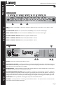
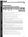
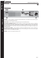
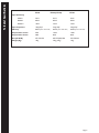
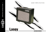
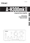
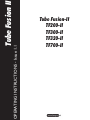
OPERATING INSTRUCTIONS - Issue 1.1
Tube Fusion II
Tube Fusion-II
TF200-II
TF300-II
TF320-II
TF700-II
Laney
OPERATING INSTRUCTIONS
IMPORTANT SAFETY INSTRUCTIONS
WARNING: When using electric products, basic cautions should always be followed, including the following.
1.
2.
3.
4.
5.
6.
7.
8.
9.
10.
11.
12.
13.
14.
15.
16.
17.
18.
Read all safety and operating instructions before using this product
All safety and operating instructions should be retained for future reference
Obey all cautions in the Operating instructions and on the back of the unit
All operating instructions should be followed
This product should not be used near water, i.e. a bathtub, sink, swimming pool, wet basement, etc.
This product should be located so that its position does not interfere with its proper ventilation. It should not
be placed flat against a wall or placed in a built up enclosure that will impede the flow of cooling air.
This product should not be placed near a source of heat such as stove, radiator, or another heat producing
amplifier.
Connect only to a power supply of the type marker on the unit adjacent to the power supply cord.
Never break off the ground pin on a power supply cord.
Power supply cords should always be handled carefully. Never walk or place equipment on power supply
cords. Periodically check cords for cuts or signs of stress, especially at the plug and the point where the
chord exits the unit.
The power supply cord should be unplugged when the unit is to be unused for long periods of time.
If this product is to be mounted in an equipment rack, rear support should be provided.
The user should allow easy access to any mains plug, mains coupler and mains switch used in conjunction
with this unit thus making it readily operable.
Metal parts can be cleaned with a damp cloth. The vinyl covering used on some units can be cleaned with
a damp cloth or ammonia based household cleaner if necessary. Disconnect the unit from the power
supply before cleaning.
Care should be taken so that objects do not fall and liquids are not spilled into the unit through any
ventilation holes or openings. On no account place drinks on the unit.
A qualified service technician should check the unit if:
The power cord has been damaged
Anything has fallen or spilled into the unit
The unit does not appear to operate correctly
The unit has been dropped or the enclosure damaged.
The user should not attempt to service the equipment. All service work is done by a qualified
service technician.
Exposure to extremely high noise levels may cause a permanent hearing gloss. Individuals vary
considerably in susceptibility to noise induced hearing loss, but nearly everyone will lose some hearing if
exposed to sufficiently intense noise for a sufficient time. The U.S. Government's Occupational Safety and
Health Administration (OSHA) has specified the following permissible noise level exposure.
Duration Per Day In Hours
8
6
4
3
2
1 12
1
12
14
or less
Sound Level dBA, slow response
90
92
95
97
100
102
105
110
115
According to OSHA, any exposure in excess of the above permissible limits could result in some hearing loss. Ear
plugs or protectors in the ear canals or over the ears must be worn when operating this amplification system in
order to prevent a permanent hearing loss if exposure exceeds the limits set forth above. To ensure against
potentially dangerous exposure to high sound pressure levels it is recommended that all persons exposed to
equipment capable of producing high sound pressure levels such as this amplification system be protected by
hearing protectors while this unit is in operation.
SAVE THESE INSTRUCTIONS
Laney
A
!
OPERATING INSTRUCTIONS
Intended to alert the user to the presence of uninsulated dangerous voltage within the product s enclosure that
may be of sufficient to constitute a risk of electrical shock to persons
Intended to alert the user of the presence of important operating and maintainance (servicing)
instructions in the literature accompanying the product
CAUTION:
Risk of electrical shock - DO NOT OPEN
CAUTION:
To reduce the risk of electircal shock, do not remove the cover. No user servicable parts inside. Refer
servicing to qualified service personnel.
WARNING:
A
!
To prevent electrical shock or fire hazard, do not expose this appliance to rain or moisture. Before using this
appliance please read the operating instructions for further warnings
Este simbolo tiene el proposito de alertar al usuario de la presencia de (voltaje) peligroso que no tiene
aislamiento dentro de la caja del producto que puede tener una magnitud suficiente como para constituir riesgo
de corrientazo
Este simbolo tiene el proposito de alertar al usario de la presencis de instruccones
importantes sobre la operacion y mantenimiento en la literatura que viene con el producto
PRECAUCION:
Riesgo de corrientazo - no abra
PRECAUCION:
Para disminuir el riesgo de carrientazo, no abra la cubierta. No hay piezas adentro que el pueda
reparar. Deje todo mantenimiento a los tecnicos calificadod
evitar corrientazos o peligro de incendio, no deja expuesto a la lluvia o humedad este aparato Antes de
ADVERTENCIA: Para
usar este aparato, lea mas advertcias en la guia de operacion
A
!
Ce symbole est utilise pur indiquer a l utilisateur de ce produit de tension non-isolee dangereuse pouvant etre
d intensite suffisante pour constituer un risque de choc electrique.
Ce symbole est utilise pour indiquer a l utilisanter qu il ou qu elle trouvera d importantes instrucions sur
l utilisation et l entrerien (service) de l appareil dans la litterature accompagnant le produit
ATTENTION:
Risques de choc electrique - NE PAS OUVIRIR
ATTENTION:
Afin de reduire le risque de choc electrique, ne pas enlever le couvercle. Il ne se trouve a l interieur
aucune piece pouvant etre reparee par l utilisateur. Confier l entretien a un personnel qualifie.
AVERTISSEMENT:
A
!
Afin de prevenir les risques de decharge electrique ou de feu, n exposez pas cet appareil a la pluie ou
a l humidite. Avant d utiliser cet appareil, lisez les avertissements supplentaires situes dans le guide.
Dieses Symbol soll den Anwender vor unsolierten gefahrlichen Spannungen innerhalb des Gehauses warnen,
die von Ausreichender Starke sind, um einen elektrischen Schlag verursachen zu konnen.
Dieses Symbol soll den Benutzer auf wichtige Instruktionen in der Bedienungsanleitung
aufmerksam machen, die Handhabung und Wartung des Produkts betreffen.
VORSICHT:
Risiko - Elektrischer Schlag! Nicht offen!
VORSICHT:
Um das Risiko eines elektrischen Schlages zu vermeiden, nicht die Abdeckung enfernen. Es befinden
sich keine Teile darin, die vom Anwender repariert werden Konnten. Reparaturen nur von qualifiziertem
Fachpersonal durchfuhren lassen
ACHTUNG
Um einen elektrischen Schlag oder Feuergefahr zu vermeiden, sollte dieses Gerat nicht dem Regen oder
Feuchtigkeit ausgesetzt werden. Vor Inbetriebnahme unbedingt die Bedienungsanleitung lesen.
Laney
OPERATING INSTRUCTIONS
Eng
INTRODUCTION
Congratulations on your decision to purchase a LaneyTube Fusion amplifier.
Laney products are designed with ease of operation as a primary objective, however to ensure you derive the
best from your new amplifier, it is important you take time to read this user manual and to familiarise yourself
with the control functions and facilities available.
BEFORE SWITCHING ON
After unpacking your amplifier check that it is factory fitted with a three pin 'grounded' (or earthed) plug. Before
plugging into the power supply ensure you are connecting to a grounded earth outlet.
If you should wish to change the factory fitted plug yourself, ensure that the wiring convention applicable to the
country where the amplifier is to be used is strictly conformed to. As an example in the United Kingdom the
cable colour code for connections are as follows.
EARTH OR GROUND - GREEN/YELLOW
NEUTRAL - BLUE
LIVE - BROWN
This manual has been written for easy access of information. The front and rear panels of each unit are graphically
illustrated, with each control and feature numbered. For a description of the function of each control feature,
simply check the number with the explanations adjacent to each panel.
Your Laney amplifier has undergone a thorough two stage,pre-delivery inspection,involving actual play testing,as
well as burn in.
When you first receive your LaneyTube Fusioin amp,follow these simple procedures:
(i) Ensure that the amplifier is set at the correct voltage for the country it is to be used in.
(Ii) Connect your instrument with a high quality shielded instrument cable. Use of cheap cables will compromise
the sound of your instrument and your amplifier.
Care of your Laney amplifier will prolong it's life.....and yours!.
Page 2
Tube Fusion -II
Laney
OPERATING INSTRUCTIONS
Eng
TF200-II Front Panel
3
2
1
3
4
5
8
1
5
6
7
9
0
CLEAN
19
3
4
5
6
7
82
1
10
VOLUME
4
2
9
0
INPUT
3
7
10
BASS
3
4
5
1
9
0
10
MIDDLE
3
7
82
8
1
5
6
7
9
0
DRIVE1
20
3
4
5
10
GAIN
3
7
8
1
0
4
5
6
7
1
10
9
0
VOLUME DRIVE2
10
GAIN
15 16 17
DRIVE EQ
3
4
5
6
7
82
2
9
14
13
12
DRIVE 2
SCOOP
6
82
1
10
TREBLE
4
2
9
0
DRIVE 1
SCOOP
6
9 10 11
8
7
6
5
CLEAN CHANNEL
BRIGHT
6
2
4
3
5
4
6
7
82
1
9
0
10
4
5
9
10
0
BASS
REVERB
6
7
82
1
VOLUME
3
3
4
5
6
9
0
10
MIDDLE
3
7
82
1
18
8
1
6
7
9
0
VIBE
3
4
5
6
7
82
1
10
TREBLE
5
2
9
0
4
10
CLEAN
REVERB
8
1
9
0
10
USION
TUBE F
DRIVE
REVERB
0
POWER
21
1
INPUT: This socket should be used for connecting the instrument to the amplifier.
2
VOLUME: Adjusts the overall volume of the clean channel.
3
BRIGHT SWITCH: Adds brightness and sparkle to the upper frequencies of the clean channel.
4
BASS: Controls the clean channel low-frequency-EQ in the pre-amplifier.
5
MIDDLE: Controls the clean channel mid-frequency-EQ in the pre-amplifier.
6
TREBLE: Controls the clean channel high-frequency-EQ in the pre-amplifier.
7
SCOOP - Drive 1: The scoop control radically cuts the level of mid range frequencies present in the
sound giving you a very modern, aggressive lead tone.
8
GAIN: Sets the level of gain on the drive channel 1. For optimum results the gain control should be
used in conjunction with the volume control (9). Setting low levels of gain with high levels of volume will
result in a nice crisp bluesy lead tone. Setting the gain control to midway with a medium volume level will
give you a punchy hard rock lead tone and setting the gain to maximum and backing the volume off, gives
you a full on metal lead tone. Obviously the type of guitar you use will have an effect on the overall sound
you hear, but the above settings are meant as an indication of the different sounds that can be achieved.
9
VOLUME: Adjusts the overall volume of the drive channel 1.
10
1
SCOOP- Drive 2: The scoop control radically cuts the level of mid range frequencies present in the
sound giving you a very modern, aggressive lead tone.
11
GAIN: Sets the level of gain on the drive channel 2. For optimum results the gain control should be
used in conjunction with the volume control (12). Setting low levels of gain with high levels of volume will
result in a nice crisp bluesy lead tone. Setting the gain control to midway with a medium volume level will
give you a punchy hard rock lead tone and setting the gain to maximum and backing the volume off, gives
you a full on metal lead tone. Obviously the type of guitar you use will have an effect on the overall sound
you hear, but the above settings are meant as an indication of the different sounds that can be achieved.
12
VOLUME: Adjusts the overall listening volume of the drive channel 2.
13
BASS: Shared Bass EQ control for drive channels 1 & 2, sets low end frequency response.
14
MIDDLE: Shared MIDs EQ control for drive channels 1 & 2, sets Mid frequency response.
15
TREBLE: Shared Treble EQ control for drive channels 1 & 2, sets high end frequency response.
Page 3
Tube Fusion -II
Laney
OPERATING INSTRUCTIONS
Eng
TF200-II Front Panel
3
2
1
3
4
5
3
7
8
1
6
7
9
4
5
6
7
BASS
3
4
5
9
0
10
8
6
7
3
4
5
9
10
GAIN
3
7
8
1
0
4
5
6
7
1
10
9
0
VOLUME DRIVE2
10
GAIN
15 16 17
DRIVE EQ
3
4
5
6
7
82
2
9
14
13
12
DRIVE 2
SCOOP
6
82
0
DRIVE1
20
19
5
1
10
TREBLE
4
2
9
0
MIDDLE
3
7
1
DRIVE 1
SCOOP
6
82
1
10
0
CLEAN
3
82
1
10
VOLUME
5
2
9
0
4
9 10 11
8
7
6
5
CLEAN CHANNEL
BRIGHT
6
2
INPUT
4
3
4
5
6
7
82
1
9
0
10
4
5
9
0
10
BASS
REVERB
6
7
82
1
VOLUME
3
3
4
5
6
9
0
8
1
10
MIDDLE
3
7
82
1
18
6
7
9
0
VIBE
3
4
5
6
7
82
1
10
TREBLE
5
2
9
0
4
10
CLEAN
REVERB
8
1
9
0
10
1
USION
TUBE F
0
DRIVE
REVERB
POWER
21
16
VIBE: Generates a radical EQ cut and boost. Difficult to explain but easy to hear! Give it a try. Works on both
channels.
17
CLEAN REVERB LEVEL: Sets the overall level of REVERB present in the clean channel signal.
18
DRIVE REVERB LEVEL: Sets the overall level of REVERB present in the drive channel signal.
19
CLEAN CHANNEL SWITCH: Selects the amplifiers CLEAN channel.
20
DRIVE 1 CHANNEL SWITCH: Selects the amplifiers DRIVE 1 channel.
21
DRIVE 2 CHANNEL SWITCH: Selects the amplifiers DRIVE 2 channel.
TF200-II Rear Panel
22
MADE IN CHINA
MAXIMUM POWER CONSUMPTION
120 WATTS ~50/60 HZ
T2A L ~115V
T1A L ~230V
FUSE RATING & SUPPLY VOLTAGE.
23
WARNING - TO REDUCE THE RISK OF FIRE OR ELECTRIC SHOCK
DO NOT EXPOSE THIS APPLIANCE TO RAIN OR MOISTURE.
CAUTION - FOR CONTINUED PROTECTION AGAINST RISK OF FIRE
REPLACE ONLY WITH SAME TYPE AND RATED FUSE.
CAUTION - TO REDUCE THE RISK OF ELECTRIC SHOCK DO NOT
REMOVE COVERS.NO USER SERVICEABLE PARTS INSIDE. REFER
SERVICING TO QUALIFIED PERSONNEL ONLY.
WARNING - THIS EQUIPMENT MUST BE EARTHED.
ATTENTION - REMPLACER LE FUSIBLE SEULEMENT PAR LE MEME
TYPE ET LE MEME CALIBRE.
AVIS - RISQUE DE CHOC ELECTRIQUE - NE PAS OUVRIR.
ATTENTION - DEBRANCHER LE CORDON D, ALIMENTATION
AVANT TOUTE INTERVENTION.
CAUTION
RISK OF ELECTRIC SHOCK DO NOT OPEN
!
Designed in the UK by BLT Industries LTD.
Laney
Footswitch
Use With Dedicated
TF3 Way Footswitch only.
Extension
Loudspeaker
8 OHM
MINIMUM IMPEDANCE
Head Phones
FX Return
FX Send
26
27
N1646
Serial Number
24
25
22
POWER: Socket for connecting external power source.
23
FOOTSWITCH SOCKET: Socket provided for connecting the supplied TF footswitch. The TF footswitch is a
dedicated footswitch forTF amplifiers please do not attempt to connect anything other than theTF footswitch supplied
as this may result in serious damage to your amplifier.
24
HEADPHONES: Socket provided for connecting pair of quality headphones. When headphones are connected to
the amplifier the output from the on board speaker is muted.
25
EXTENSION SPEAKER SOCKET: Socket provided for connecting an external speaker enclosure. NOTE The
minimum impedance of any speaker cabinet connected to you amplifier must not be less than 8 Ohms. Connecting a
load of less than 8 Ohms will result in your amplifier overheating. Whilst this is not a problem in the short term,
prolonged use in this manner will result in permanent damage to your amplifier and voiding of your amplifiers guarantee.
26
FX RETURN : Socket provided for connecting the output of an external effects device.
27
FX SEND : Socket provided for connecting an external effects device. The output from this socket should be
connected to the external effect devices input.
Page 4
Tube Fusion -II
Laney
OPERATING INSTRUCTIONS
Eng
TF300-II/TF320-II/TF700-II* Front Panel
3
2
1
3
4
5
8
1
5
6
7
9
0
CLEAN
19
3
4
5
6
7
82
1
10
VOLUME
4
2
9
0
INPUT
3
7
10
BASS
3
4
5
1
9
0
10
MIDDLE
SCOOP
6
3
7
82
8
1
5
6
7
9
0
DRIVE1
20
3
4
5
10
GAIN
3
7
8
1
0
4
5
6
7
10
1
9
0
VOLUME DRIVE2
10
GAIN
15 16 17
DRIVE EQ
3
4
5
6
7
82
2
9
14
13
DRIVE 2
SCOOP
6
82
1
10
TREBLE
DRIVE 1
4
2
9
0
9 10 11 12
8
7
6
5
CLEAN CHANNEL
BRIGHT
6
2
4
3
4
5
6
7
82
1
9
0
10
VOLUME
3
4
5
1
9
0
7
10
3
4
5
6
9
0
10
MIDDLE
3
7
82
1
BASS
REVERB
6
82
18
8
1
6
7
VIBE
3
4
5
6
7
82
9
0
10
TREBLE
5
1
9
0
4
2
10
CLEAN
REVERB
21
9
0
10
DRIVE
REVERB
INPUT: This socket should be used for connecting the instrument to the amplifier.
2
VOLUME: Adjusts the overall volume of the clean channel.
3
BRIGHT SWITCH: Adds brightness and sparkle to the upper frequencies of the clean channel.
4
BASS: Controls the clean channel low-frequency-EQ in the pre-amplifier.
5
MIDDLE: Controls the clean channel mid-frequency-EQ in the pre-amplifier.
6
TREBLE: Controls the clean channel high-frequency-EQ in the pre-amplifier.
8
9
10
11
0
POWER
*TF700 - features identical pre amp to TF300
apart from being reversed
1
7
1
8
1
SCOOP - Drive 1: The scoop control radically cuts the level of mid range frequencies present in the
sound giving you a very modern, aggressive lead tone.
GAIN: Sets the level of gain on the drive channel 1. For optimum results the gain control should be
used in conjunction with the volume control (9). Setting low levels of gain with high levels of volume will
result in a nice crisp bluesy lead tone. Setting the gain control to midway with a medium volume level will
give you a punchy hard rock lead tone and setting the gain to maximum and backing the volume off, gives
you a full on metal lead tone. Obviously the type of guitar you use will have an effect on the overall sound
you hear, but the above settings are meant as an indication of the different sounds that can be achieved.
VOLUME: Adjusts the overall volume of the drive channel 1.
SCOOP- Drive 2: The scoop control radically cuts the level of mid range frequencies present in the
sound giving you a very modern, aggressive lead tone.
GAIN: Sets the level of gain on the drive channel 2. For optimum results the gain control should be
used in conjunction with the volume control (12). Setting low levels of gain with high levels of volume will
result in a nice crisp bluesy lead tone. Setting the gain control to midway with a medium volume level will
give you a punchy hard rock lead tone and setting the gain to maximum and backing the volume off, gives
you a full on metal lead tone. Obviously the type of guitar you use will have an effect on the overall sound
you hear, but the above settings are meant as an indication of the different sounds that can be achieved.
12
VOLUME: Adjusts the overall listening volume of the drive channel 2.
13
BASS: Shared Bass EQ control for drive channels 1 & 2, sets low end frequency response.
14
MIDDLE: Shared MIDs EQ control for drive channels 1 & 2, sets Mid frequency response.
15
TREBLE: Shared Treble EQ control for drive channels 1 & 2, sets high end frequency response.
Page 5
Tube Fusion -II
Laney
OPERATING INSTRUCTIONS
Eng
TF300-II/TF320-II/ TF700-II* Front Panel
3
2
1
4
CLEAN CHANNEL
9 10 11
8
7
6
5
DRIVE 1
DRIVE 2
B
S
S Front Panel
TF300-II/ TF320-II/TF700-II*
3
4
5
1
INPUT
RIGHT
6
3
7
8
2
1
0
2
10
VOLUME
9
4
5
6
7
3
CLEAN
3
4
5
6
7
1
9
4
10
0
BASS
3
4
5
1
9
0
5
10
MIDDLE
COOP
6
3
7
82
82
2
8
1
9
0
10
TREBLE
6D
RIVE1
20
19
5
4
6
7
1
3
4
5
7G
0
9
10
AIN
COOP
6
3
7
82
2
8
1
8V
0
9
10
OLUME
4
5
6
7
1
9
5
4
6
7
10
AIN
3
4
5
6
7
82
1
11V
9 10
G
0
15 16 17
DRIVE EQ
3
82
2
DRIVE2
14
13
12
0
9
10
OLUME
3
4
5
1
12B
0
9
10
ASS
REVERB
6
7
82
3
4
5
6
13
M
0
9
10
IDDLE
1
3
7
82
1
18
8
14
T
0
9
10
REBLE
4
5
6
7
3
4
5
6
7
82
2
1
9
8
1
15RC 16 RD17
0
VIBE
10
LEAN
EVERB
10
0
RIVE
EVERB
9
USION
1
TUBE F
0
18
POWER
21
16
VIBE: Generates a radical EQ cut and boost. Difficult to explain but easy to hear! Give it a try. Works on both
channels.
17
CLEAN REVERB LEVEL: Sets the overall level of REVERB present in the clean channel signal.
18
DRIVE REVERB LEVEL: Sets the overall level of REVERB present in the drive channel signal.
19
CLEAN CHANNEL SWITCH: Selects the amplifiers CLEAN channel.
20
DRIVE 1 CHANNEL SWITCH: Selects the amplifiers DRIVE 1 channel.
21
DRIVE 2 CHANNEL SWITCH: Selects the amplifiers DRIVE 2 channel.
TF300-II/ TF320-II Rear Panel
22
WARNING - TO REDUCE THE RISK OF FIRE OR ELECTRIC SHOCK
MADE IN CHINA
NOT EXPOSE THIS APPLIANCE TO RAIN OR MOISTURE.
MAXIMUM POWER CONSUMPTION CDOAUTION
- FOR CONTINUED PROTECTION AGAINST RISK OF
300 WATTS ~50/60 HZ FIRE REPLACE ONLY WITH SAME TYPE AND RATED FUSE.
CAUTION - TO REDUCE THE RISK OF ELECTRIC SHOCK DO NOT
REMOVE COVERS.NO USER SERVICEABLE PARTS INSIDE. REFER
SERVICING TO QUALIFIED PERSONNEL ONLY.
WARNING - THIS EQUIPMENT MUST BE EARTHED.
ATTENTION - REMPLACER LE FUSIBLE SEULEMENT PAR LE
MEME TYPE ET LE MEME CALIBRE.
AVIS - RISQUE DE CHOC ELECTRIQUE - NE PAS OUVRIR.
ATTENTION - DEBRANCHER LE CORDON D ALIMENTATION
AVANT TOUTE INTERVENTION.
T5A L ~115V
T2A L ~230V
CAUTION
RISK OF ELECTRIC SHOCK DO NOT OPEN
!
FUSE RATING & SUPPLY VOLTAGE. Designed in the UK by BLT Industries LTD.
Laney
23
Footswitch
Extension
Loudspeaker
Use WithDedicated
TF3 Way Footswitch only.
8 OHM
MINIMUM IMPEDANCE
FXReturn
FXSend
N1646
SERIAL NUMBER
24
25
26
22
POWER: Socket for connecting external power source.
23
FOOTSWITCH SOCKET: Socket provided for connecting the supplied TF footswitch. The TF footswitch is a
dedicated footswitch forTF amplifiers please do not attempt to connect anything other than theTF footswitch supplied
as this may result in serious damage to your amplifier.
24
EXTENSION SPEAKER SOCKET: Socket provided for connecting an external speaker enclosure. NOTE The
minimum impedance of any speaker cabinet connected to you amplifier must not be less than 8 Ohms. Connecting a
load of less than 8 Ohms will result in your amplifier overheating. Whilst this is not a problem in the short term,
prolonged use in this manner will result in permanent damage to your amplifier and voiding of your amplifiers
guarantee.
25
FX RETURN : Socket provided for connecting the output of an external effects device.
26
FX SEND : Socket provided for connecting an external effects device. The output from this socket should be
connected to the external effect devices input.
Page 6
Tube Fusion -II
Laney
OPERATING INSTRUCTIONS
Eng
TF700-II Rear Panel
23
22
FXSend
FXReturn
24
Loudspeakers
4 OHM TOTAL MINIMUM IMPEDANCE
REFER TO USER MANUAL FOR
RECOMMENDED CONNECTION
Footswitch
Use With Dedicated
TF3 Way Footswitch only.
Laney
WARNING - TO REDUCE THE RISK OF FIRE OR ELECTRIC SHOCK
DO NOT EXPOSE THIS APPLIANCE TO RAIN OR MOISTURE.
CAUTION - FOR CONTINUED PROTECTION AGAINST RISK OF
FIRE REPLACE ONLY WITH SAME TYPE AND RATED FUSE.
CAUTION - TO REDUCE THE RISK OF ELECTRIC SHOCK DO NOT
REMOVE COVERS.NO USER SERVICEABLE PARTS INSIDE. REFER
SERVICING TO QUALIFIED PERSONNEL ONLY.
WARNING - THIS EQUIPMENT MUST BE EARTHED.
ATTENTION - REMPLACER LE FUSIBLE SEULEMENT PAR LE
MEME TYPE ET LE MEME CALIBRE.
AVIS - RISQUE DE CHOC ELECTRIQUE - NE, PAS OUVRIR.
ATTENTION - DEBRANCHER LE CORDON D ALIMENTATION
AVANT TOUTE INTERVENTION.
CAUTION
RISK OF ELECTRIC SHOCK DO NOT OPEN
MADE IN CHINA
FUSE RATING & SUPPLY VOLTAGE.
T5A L ~115V
T2A L ~230V
!
Designed in the UK by BLT Industries LTD.
N1646
MAXIMUM POWER CONSUMPTION
300 WATTS ~50/60 HZ
SERIAL NUMBER
25
26
22
FX SEND : Socket provided for connecting an external effects device. The output from this socket should be
connected to the external effect devices input.
23
FX RETURN : Socket provided for connecting the output of an external effects device.
24
EXTENSION SPEAKER SOCKET: Sockets provided for connecting external speaker enclosures. NOTE The
minimum impedance of any single speaker cabinet connected to you amplifier must not be less than 8 Ohms.
Connecting a total load of less than 4 Ohms will result in your amplifier overheating. Whilst this is not a problem in the
short term, prolonged use in this manner will result in permanent damage to your amplifier and voiding of your
amplifiers guarantee.
25
FOOTSWITCH SOCKET: Socket provided for connecting the supplied TF footswitch. The TF footswitch is a
dedicated footswitch forTF amplifiers please do not attempt to connect anything other than theTF footswitch supplied
as this may result in serious damage to your amplifier.
26
POWER: Socket for connecting external power source.
Page 7
Notes
Page 8
Technical Specificatioins
TF200
TF300 /(TF320)
TF700
Input Sensitivity
Clean
20mV
20mV
20mV
Drive 1
850uV
850uV
850uV
Drive 2
100uV
100uV
100uV
Input Impedance
1Meg/47pF
1Meg/47pF
1Meg/47pF
FX Loop
850mV(Zout 1K/Zin 22K)
850mV(Zout 1K/Zin 22K)
850mV(Zout 1K/Zin 22K)
Output Power 4 ohm
65W
120W
120W
Output Power 8 ohm
48W
80W
80W
Size (H*W*D)
475*534*270
485*575(680)*280
255*578*242
Weight (Kg)
16Kg
18Kg (24kg)
12Kg
Page 9
Laney
POWER TO THE MUSIC
In the interest of continued product development BLT Industries Ltd. Reserves the right to amend product specification without prior notification.