1
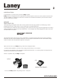
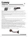
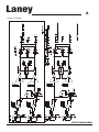
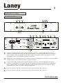
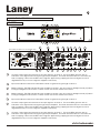
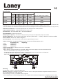
Laney
CA
SERIES
Power Amplifiers
OPERATING MANUAL
V1
Laney
2
INTRODUCTION
Congratulations on your decision to purchase a Laney amplifier.
Laney products are designed with ease of operation as a primary objective, however to ensure you derive the best from
your new amplifier, it is important you take time to read this user manual and to familiarise yourself with the control
functions and facilities available
BEFORE
SWITCHING ON
After unpacking your amplifier check that it is factory fitted with a three pin 'grounded' (or earthed) plug. Before
plugging into the power supply ensure you are connecting to a grounded earth outlet.
If you should wish to change the factory fitted plug yourself, ensure that the wiring convention applicable to the country
where the amplifier is to be used is strictly conformed to. As an example in the United Kingdom the cable colour code
for connections are as follows.
EARTH OR GROUND - GREEN/YELLOW
NEUTRAL - BLUE
LIVE - BROWN
This manual has been written for easy access of information. The front and rear panels of each unit are graphically
illustrated, with each control and feature numbered. For a description of the function of each control feature, simply
check the number with the explanations adjacent to each panel.
When you first recieve your Laney CA amp, follow these simple procedures:
(i) Ensure that the amplifier is set at the correct voltage for the country it is to be used in.
(ii) Connect your instrument with a high quality shielded instrument cable. Use of cheap cables will compromise the
sound of your instrument and your amplifier.
If there is a problem with your Laney CA amplifier
DON'T
DO
PHONE YOUR DEALER!
Care of your Laney amplifier will prolong it's life.....and yours!.
CA MANUAL
Laney
3
IMPORTANT SAFETY INSTRUCTIONS
WARNING: When using electric products, basic cautions should always be followed, including the following.
1.
2.
3.
4.
5.
6.
7.
8.
9.
10.
11.
12.
13.
14.
15.
16.
17.
Read all safety and operating instructions before using this product
All safety and operating instructions should be retained for future reference
Obey all cautions in the Operating instructions and on the back of the unit
All operating instructions should be followed
This product should not be used near water, i.e. a bathtub, sink, swimming pool, wet basement, etc.
This product should be located so that its position does not interfere with its proper ventilation. It should not
be placed flat against a wall or placed in a built up enclosure that will impede the flow of cooling air.
This product should not be placed near a source of heat such as stove, radiator, or another heat producing
amplifier.
Connect only to a power supply of the type marked on the unit adjacent to the power supply cord.
Never break off the ground pin on a power supply cord.
Power supply cords should always be handled carefully. Never walk or place equipment on power supply
cords. Periodically check cords for cuts or signs of stress, especially at the plug and the point where the
chord exits the unit.
The power supply cord should be unplugged when the unit is to be unused for long periods of time.
If this product is to be mounted in an equipment rack, rear support should be provided.
Metal parts can be cleaned with a damp cloth. The vinyl covering used on some units can be cleaned with
a damp cloth or ammonia based household cleaner if necessary. Disconnect the unit from the power
supply before cleaning.
Care should be taken so that objects do not fall and liquids are not spilled into the unit through any
ventilation holes or openings.
A qualified service technician should check the unit if:
The power cord has been damaged
Anything has fallen or spilled into the unit
The unit does not appear to operate correctly
The unit has been dropped or the enclosure damaged.
The user should not attempt to service the equipment. All service work is done by a qualified
service technician.
Exposure to extremely high noise levels may cause a permanent hearing loss. Individuals vary
considerably in susceptibility to noise induced hearing loss, but nearly everyone will lose some hearing if
exposed to sufficiently intense noise for a sufficient time. The U.S. Government's Occupational Safety and
Health Administration (OSHA) has specified the following permissible noise level exposure.
Duration Per Day In Hours
Sound Level dBA, slow response
8
90
6
92
4
95
3
97
2
100
1½
102
1
105
½
110
¼ or less
115
According to OSHA, any exposure in excess of the above permissible limits could result in some hearing loss. Ear
plugs or protectors in the ear canals or over the ears must be worn when operating this amplification system in
order to prevent a permanent hearing loss if exposure exceeds the limits set forth above. To ensure against
potentially dangerous exposure to high sound pressure levels it is recommended that all persons exposed to
equipment capable of producing high sound pressure levels such as this amplification system be protected by
hearing protectors while this unit is in operation.
Lightning Bolt Symbol:
This symbol is used to alert the user to the presence
of dangerous voltages and the possible risk of
electric shock.
!
Exclamation Mark Symbol:
This symbol is used to alert the user to make special note of
important operating or maintenance instructions found in the
reference manual.
SAVE THESE INSTRUCTIONS
CA MANUAL
Laney
4
Indroduction
The CA range of amplifiers use a new power output topology. This enables a design which has all the high
efficiency benefits of a class D type digital topology but without the usual draw backs of poor distortion and
difficult to control EMC problems. The CA design uses microprocessor-controlled high frequency switching of state
of the art output power FETs.
Most switching amplifiers work at frequencies of around 200kHz. The CA runs at varying rates depending on the
input signal from 600kHz to 1.2Mhz. This has many benefits both to efficiency and sonic performance.
The heart of the design uses thick film technology for high reliability and consistency. The power supply is a
conventional massive oversized toroidal design avoiding the problems of instant transient power delivery and
unreliability associated with many switch mode designs.
Due to the very high efficiency (typically 85-90%), noisy unreliable, fans are eliminated in favor of an aluminium
chassis and side mounted heat-sink extrusions.
The amplifier has the unique ability to look like a near perfect "audio modulated" power supply. This gives big
advantages when driving difficult loads where impedance's vary over the frequency spectrum the CA amplifier is
unaffected and drives the loads much more perfectly giving a dramatically improved performance to many
speaker systems.
The amplifiers also contain microprocessor controlled soft clipping and user switchable limiter* circuitry.
*(Factory fitted option only together with VCA control - Part Number LMT3000)
Speakon(TM) connectors are used for the outputs and a combination of electronically balanced XLR/Jack inputs.
The input gain is internally selectable by jumper links from +4dBu to 0dbu or to 26dB gain. (See later for
description) There are also input level controls on the fascia panel to attenuate down from the preset levels with
associated five band LED level displays.
The rear panel features bridge /mono mode switching and a signal earth lift.
The amplifier avoids the use of conventional unreliable fuses and uses automatically resetting devices for the
internal electronics and a front panel mounted manual re-settable overload cutout.
Protection circuitry covers over and under voltage operation, short /open circuit load conditions, DC Voltage and
excessive input signals.
Soft start circuitry is included to reduce switch on surges from the mains power. Automatic output muting is
included to avoid extraneous noise appearing at the speakers at turn on and turn off from the amplifier or other
units in the sound system.
Much work has been carried out to ensure EMC compliance is well within European and US standards for present
and future standards.
Three models are currently available:
CA600
CA1500
CA3000
Applications include, use as recording studio monitor and stereo broadcast amplifier, Professional PA amplifier,
and Esoteric hi-fi amplifier etc.
To gain maximum benefit from your amplifier please read and understand the instructions in this handbook. The
amplifiers have been created to meet any condition you may use them for. Enjoy.
CA MANUAL
Laney
5
Input Wiring
The CA amplifier is factory set to +4dB input sensitivity, and internally selectable to either 0dB, +4dB or 26dB
system. Setting the input sensitivity requires the removal of the top cover. If in any doubt, consult a qualified
service engineer. For details on changing sensitivity setting see page 13
The 1/4“ Jack and 3pin XLR inputs are wired in parallel,
1
2
3
Pin1. Ground
Pin2. Hot
Pin3. Col
Sleeve = Screen (GND)
Ring = Cold
Tip = Hot
Tips.
1. For all input wiring use good quality shielded wire only. Cables with foil wrap shield or a high density braid are
superior. Cables with stranded spiral shield, although flexible, will break down over time and coase noise
problems.
2. Try to avoid unbalanced lines with professional equipment. If you have no choice, keep the cables as short as
possible.
3. To minimise hum and crosstalk, avoid running low level input, high level output and AC power feeds in the same
path. Try to run differing signal paths at 90 degrees to each other. If you must use a common path for all cables,
use a star-quad cable for the low level signals.
4. When changing input connectors or wiring, Always turn the amplifier volume controls all the way down(anticlockwise)
5. When changing output connectors, always turn the amplifier volume levels fully down, and preferably, switch off
mains supply.
Output Wiring
1. To maintain good bass response, Always use the lowest DC resistance cable you can afford which will terminate
safely in your connector
2 To prevent short circuits, Always wrap or otherwise insulate exposed loudspeaker cable connectors.
3. Do not use connectors that could accidently tie conductors together. Eg. Standard 1/4“ jacks.
4. Never use connectors that could accidentally be plugged into an AC power outlet.
5. Avoid connectors with low current carrying capacity, such as XLRs
6. Never use the 2+,2- pins on the output speakon(tm) unless you specifically need them. Eg for biamping.
What gauge speaker wire should I use in my system? For the best speaker damping and least amount of power
loss you will want to use the heaviest gauge that is practical. The length of the speaker wire should be considered
when considering wire gauge. The shorter the run, the smaller gauge you can use with minimum power and
damping factor loss. The longer the run, the heavier gauge you will need to minimise power and damping factor
loss. You will also want to consider the size of power amplifier you are using. The larger the amplifier, the heavier
gauge you will want to use. For general use consider 2mm2 or above.
Can I run one channel of my CA Amplifier at a different impedance than the other channel?
Yes. All CA amplifiers can be treated as if they are two separate "mono" amplifiers (One channel completely
independent of the other) For example: A CA1500 can function with a single 8 ohm speaker on channel one and
two 8 ohm speakers on channel two.
- Pin configuration. Wiring a standard Neutrik NL4 Speakon ™ For normal operation.
2+
2-
1+
1-
+
CA MANUAL
(via a single cable)
(via a single cable)
Laney
6
System Diagram
CA MANUAL
Laney
7
explanation of terms
CA600/CA1500
2
1
4
7
Laney
Concept Power
Clip
-3-9-12Signal
0dB
Channel 1
5
8
8
Bridge
0dB
Channel 2
6
Protect
0
A
CA600
Min Load
4 Ohms
15
L oc
16
17
ck
Made in the United Kingdom by BLT Industries Ltd.
nlo
Dual Mono
Stereo Bridge
L oc
k
18
Channel 1/
Dual Mono/
Bridge
Limiter
On
Off
In
Out
Ground Link
k
L oc
Amp2
1+ Amp2 Hot
1 - Amp2 Cold
2+ n/a
Min Load
2 - n/a
2 Ohms
14
ck
Bridge
13
nlo
1+ Hot
1 - Cold
2+ n/a
2 - n/a
12
Channel 2
XLR Pin Connections
Pin1 - 0V
Pin2 - Hot
Pin3 - Cold
ck
Avis
Risque de choc electrique - ne pas ouvrir.
Warning
To reduce the risk of fire or electric shock do not
expose this appliance to rain or moisture.
Caution
To reduce the risk of electric shock do not remove covers.
No user serviceable parts inside. Refer servicing to
qualified personnel only.
Attention.
Debrancher le cordon d’alimentation avant toute intervention.
1
Serial No:
nlo
Caution
When using “BRIDGE”
mode only connect
speakers to the
“BRIDGE” terminal.
Push to reset
Power
k
U
CA1500 - 750Watts
CA600 - 350Watts
~115V
~230V
11
U
Power Consumption
~50-60Hz
Amp1
1+ Amp1 Hot
1 - Amp1 Cold
2+Amp2 Hot Min Load
2 - Amp2 Cold 2 Ohms
U
Supply voltage
8a
9
10
Warning
This Equipment must be earthed.
8
(Optional)
CAUTION
RISK OF ELECTRIC SHOCK DO NOT OPEN
!
Jack Pin Connections
Tip - Hot
Ring - Cold
Shield - 0V
19
1
2
4
5
6
Channel 1 input gain: Sets the level of the input signal to channel 1. The visual LED's give the user an
indication of the signal level running through the pre amplifier. The levels should be set as to minimize the
level of clipping. When the red LED is lit the signal is approaching clipping and some degree of sound
degradation may occur if the signal is clipped continuously.
Bridge indicator: This LED indicates that the amplifier is running in bridged mode (14) When running in bridged
mode channel 1's level control acts as the master level control.
Channel 2 input gain: Sets the level of the input signal to channel 1. The visual LED's give the user an
indication of the signal level running through the pre amplifier. The levels should be set as to minimise the
level of clipping. When the red LED is lit the signal is approaching clipping and some degree of sound
degradation may occur if the signal is clipped continuously.
Input level indicator channel 1: Indicates the level of signal running through channel 1
Input level indicator channel 2: Indicates the level of signal running through channel 2
CA MANUAL
Laney
7
8
8a
9
10
8
Power LED: Indicates the unit is powered up.
Reset Button: Should the unit be connected in error and experience a continuous overload situation such as
connecting the unit to an incorrect supply voltage or should the amplifier experience a catastrophic
component failure then the reset button will trip. This will cause the unit to completely shut down and all
power to the amplifier will be removed. Once the unit has tripped the reset button needs to be pushed in. If
the unit fails to reset itself immediately then the amplifier should be looked at by a qualified technician.
Consult your dealer.
Power Switch: Disable mains power to the unit.
Protect: This LED indicates that the output section of the CA amplifier has been run into extreme conditions
such as too low an impedance at too high a level for too long a period. In the situation that Protection is
engaged the output section is automatically disconnected from the speakers and then shut down. All the
other functions of the amplifier continue to function as normal but the amplifier will produce no sound. To
reactivate the amplifier it must be switched off, left for a few seconds and switched back on again, via the
main power switch (8a).
Speakon Connector amp 1: Used to connect an external speaker cabinet. The signal present at this
connection is dependent on the mode of operation of the power amp (14). In Stereo mode input signals
from channel 1 and Channel 2 are present at this socket. In Dual Mono mode only signals from Channel 1
are present. In Bridge mode this connector should not be used. Minimum impedance 2 Ohms.
11
Speakon Connector Bridge: Used to connect an external speaker cabinet when running the power amplifier
section in Bridged Mode (14). In Bridge mode only signals from Channel 1 are present. Minimum impedance
4 Ohms.
12
XLR Input Channel 2: An XLR input option is provided for Channel 2 here. Pin connections for the XLR
connection are Pin 1 0V, Pin 2 Hot and Pin 3 Cold.
13
Jack Socket Channel 2: A jack-input option is provided for Channel 2 here
14
15
16
17
18
19
Power amp mode switch: This switch selects the mode of operation of the CA power amplifier section. Three
modes of operation are available Stereo, Dual Mono and Bridge. In Stereo mode the two onboard power
amplifiers run independently supplying 300 watts (CA600) 750 watts RMS (CA1500) of each channel input to
each of the two output connections (10,19). In Dual Mono mode the signal present at Channel 1 input is sent
to both amp 1 output (10) and amp 2 output (19). In Dual Mono mode channel 2 is not active. The final
mode of the power amplifier is Bridge mode. In Bridge mode each individual power amplifier section is
summed together producing maximum output. In Bridge mode Channel 1 acts as the master channel.
Please note when selecting Bridge Mode the minimum impedance is 4 Ohms.
Ground Link Switch: This switched is used to reduce unwanted interference such as multiple earth loops etc
and does so by isolating the grounds of the input sockets only.
Limiter: Activates the onboard (Optional factory fitted) Limiter which prevents the output section being driven
into clipping allowing the amplifier to be run at maximum output without experiencing unwanted distortion.
Jack Socket Channel 1: A jack-input option is provided for Channel 2 here. When the power amplifier section
is running in either Dual Mono or Bridge mode, channel 1 acts as the master input channel.
XLR Input Channel 1: An XLR input option is provided for Channel 2 here. Pin connections for the XLR
connection are Pin 1 0V, Pin 2 Hot and Pin 3 Cold. When the power amplifier section is running in either Dual
Mono or Bridge mode, channel 1 acts as the master input channel.
Speakon Connector amp 2: Used to connect an external speaker cabinet. The signal present at this
connection is dependent on the mode of operation of the power amp (14). In Stereo mode input signals
from channel 1 and Channel 2 are present at this socket. In Dual Mono mode only signals from Channel 1
are present. In Bridge mode this connector should not be used. Minimum impedance 2 Ohms.
CA MANUAL
Laney
9
explanation of terms
CA3000
53
21
Channel 2
8
Laney
Clip
-3
-9
-12
Sig
25
Channel 4
Clip
-3
-9
-12
Sig
Push To Reset
0
29
27
Push To Reset
30
Concept Power
0dB
Channel 3
8
8
24
00
CA30
1
Clip
-3
-9
-12
Sig
0dB
23
Bridge
Protect
Power
Clip
-3
-9
-12
Sig
0dB
Channel 1
26
22
8
20
0dB
31 32
28
33
34
36
35
37
38
39
40
41
Two mains sockets on 115V model only!
EUT R
N
N
IK
Min
Load
2 Ohms
IK
EUT R
Amp4
IK
N
Channel 4
Amp2
Min Load
2 Ohms
Ground Link
Out
Dual Mono In
Limiter
Stereo Bridge
On
Off
22
23
24
25
26
EUT R
N
21
Min Load
4 Ohms
(Optional)
Serial No:
NOTE: Speakon™ Pin Configuration
Amp1. 1+Hot1,1-Cold1,2+Hot2,2-Cold2
Amp3. 1+Hot3,1-Cold3,2+Hot4,2-Cold4
Made in the United Kingdom by BLT Industries Ltd.
Amp2. 1+Hot2,1-Cold2
Amp4. 1+Hot4,1-Cold4
Bridge, 1+Hot,1-Cold
Dual Mono
Stereo Bridge
Limiter
On
Off
Dual Mono/Bridge
Jack Pins
Tip - Hot
Ring - Cold
Shield - 0V
XLR Pins
Pin1 - 0V
Pin2 - Hot
Pin3 - Cold
Channel 1
(See Note)
IK
43
N
IK
20
N
42
IK
Amp3
Bridge
Channel 2
EUT R
!
EUT R
Bridge
EUT R
Supply voltage
Power Consumption
Power Consumption
Caution
~115V
1000 Watts
To reduce the risk of electric 1000 Watts
~50/60Hz
~230V
shock do not remove covers. ~50/60Hz
Attention - Remplacer le fusible seulement
No user serviceable parts
Min Load
par le meme type et le meme calibre.
inside. Refer servicing to
Attention - Se referer au manuel d’utilisation
4 Ohms
qualified personnel only.
pour la connection haut-parleurs.
Warning
Caution - For continued protection against risk of
To reduce the risk of
fire replace only with same type and rated fuse
fire or electric shock do not
Warning This equipment must be earthed.
Caution Refer to users
expose this appliance
manual for recommended (See Note)
CAUTION
to rain or moisture.
speaker connections.
RISK OF ELECTRIC SHOCK DO NOT OPEN
Attention.
Caution When using Min Load
Attention En utilisant
Avis
Debrancher le cordon bridge mode only
en mode “Bridge”,ne
Risque de choc
2 Ohms
d’alimentation avant connect speakers
electrique - ne pas ouvrir. connecter que la
toute intervention. to the bridge terminal.
sortie “BRIDGE”.
Dual Mono/Bridge
Channel 3
44
Amp1
MinLoad
2 Ohms
45
In
Out
Ground Link
46
47
48
49
(Optional)
Part:8P-5075
50
51
52
Channel 2 input gain: Sets the level of the input signal to channel 2. The visual LED's give the user an
indication of the signal level running through the pre amplifier. The levels should be set as to minimize the
level of clipping. When the red LED is lit the signal is approaching clipping and some degree of sound
degradation may occur if the signal is clipped continuously.
Input level indicator channel 2: Indicates the level of signal running through channel 2
Bridge indicator: This LED indicates that the amplifier channels 1 & 2 are running in bridged mode (37) When
running in bridged mode channel 1's level control acts as the master level control
Bridge indicator: This LED indicates that the amplifier channels 3 & 4 are running in bridged mode (37) When
running in bridged mode channel 1's level control acts as the master level control
Input level indicator channel 4: Indicates the level of signal running through channel 4
Channel 4 input gain: Sets the level of the input signal to channel 4. The visual LED's give the user an
indication of the signal level running through the pre amplifier. The levels should be set as to minimise the
level of clipping. When the red LED is lit the signal is approaching clipping and some degree of sound
degradation may occur if the signal is clipped continuously.
Channel 1 input gain: Sets the level of the input signal to channel 1. The visual LED's give the user an
indication of the signal level running through the pre amplifier. The levels should be set as to minimise the
level of clipping. When the red LED is lit the signal is approaching clipping and some degree of sound
degradation may occur if the signal is clipped continuously.
CA MANUAL
Laney
27
28
29
30
31
32
33
34
10
Input level indicator channel 1: Indicates the level of signal running through channel 1
Reset Button AMP 1 (CH1 + CH2): Should the unit be connected in error and experience a continuos overload
situation such as connecting the unit to an incorrect supply voltage or should the amplifier experience a
catastrophic component failure then the reset button will trip. This will cause the unit to completely shut down
and all power to the amplifier will be removed. Once the unit has tripped the reset button needs to be
pushed in. If the unit fails to reset itself immediately then the amplifier should be looked at by a qualified
technician. Consult your dealer.
Power switches: Used to switch each separate power amplifier unit on and off.
Reset Button AMP 1 (CH3 + CH4): Should the unit be connected in error and experience a continuos overload
situation such as connecting the unit to an incorrect supply voltage or should the amplifier experience a
catastrophic component failure then the reset button will trip. This will cause the unit to completely shut down
and all power to the amplifier will be removed. Once the unit has tripped the reset button needs to be
pushed in. If the unit fails to reset itself immediately then the amplifier should be looked at by a qualified
technician. Consult your dealer.
Input level indicator channel 3: Indicates the level of signal running through channel 3
Channel 3 input gain: Sets the level of the input signal to channel 3. The visual LED's give the user an
indication of the signal level running through the pre amplifier. The levels should be set as to minimise the
level of clipping. When the red LED is lit the signal is approaching clipping and some degree of sound
degradation may occur if the signal is clipped continuously.
Speakon Connector amp 4: Speakon connector for connecting external speaker. The signal present at this
connector is determined by the power amp mode setting (37) for this power amplifier. In Stereo Mode the
signal present is derived from Channel 4 input. In Dual Mono mode the signal present is derived from
Channel 3 input. In Bridge Mode NO signal is present at this connector.
Speakon Connector amp 2: Speakon connector for connecting external speaker. The signal present at this
connector is determined by the power amp mode setting (48) for this power amplifier. In Stereo Mode the
signal present is derived from Channel 2 input. In Dual Mono mode the signal present is derived from
Channel 1 input. In Bridge Mode NO signal is present at this connector.
35
XLR Input Channel 4: An XLR input option is provided for Channel 4 here. Pin connections for the XLR
connection are Pin 1 0V, Pin 2 Hot and Pin 3 Cold.
36
Jack Socket Channel 4: A jack-input option is provided for Channel 4 here
Speakons(TM)
For amplifiers, the most popular termination device on professional products has been the dual banana.
However, recent regulatory requirements in Europe have outlawed the use of the dual banana. It is
possible that similar regulatory controls will appear worldwide over the next few years. One solution to this
problem is to use the Neutrik Speakon™ connector. The major loudspeaker manufacturers have been
using Speakon connectors for the input termination on their products for several years now, so you can
be assured of the connector's reliability in the workplace. With Speakon (tm) connectors, you can plug
straight from the amp to the speaker, and start making those great sounds right away. The Speakon
connectors used on our amplifiers meet all known safety regulations. Once wired correctly, the
connector cannot be plugged in backwards, causing the type of inverted polarity situations that are
common with banana hookups. It will provide a safe, secure and reliable method of interfacing your
amplifier to the load.
Speakon
™
Trademark of Neutrik AG
CA MANUAL
Laney
37
11
Power amp mode switch: The CA3000 is a four channel power amplifier, Arranged as channels 1,2,3 and 4.
These are configured as two totally separate stereo amplifiers. Channel 1 and 2 are treated as a pair,
Channel 3 and 4 are treated as a pair. These channels can be used:(A) Stereo Mode. All channels run independently
(B) Dual Mono. One signal sent to both amps.
(C) Bridge.
Channel 1 and 2 can be bridged together as can 3,4
(Cont)These modes are controlled via the mode selector switch on the rear panel. Channel 1 and 2 are
controlled by (37) and channel 3 and 4 are controlled by (48)
Stereo Mode.
Dual Mono.
Bridge.
Each input is sent to its respective output.
Channel 1 input is routed to outputs 1 and 2
Channel 3 input is routed to outputs 3 and 4
Channels 2 and 4 inputs are not used.
Channel 1 input is routed to bridge connector (60)
Channel 3 input is routed to bridge connector (70)
Only the bridge terminals should be used in bridge mode
The NL4 Speakon (TM) output connectors have four pins, 1+,1-,2+,2-.
In normal operation the 1+ pin carries the hot signal, 1- the cold signal.
Channel 1 output also carries channel 2 output on 2+(hot),2-(cold)
Channel 3 output also carries channel 4 output on 2+(hot),2-(cold)
This is to aid the connection of biamped enclosures and the use of four core loudspeaker cable.
IMPORTANT! Take care not to use 2+,2- if they are not needed as some manufacturers actually join 1+
and 2+ together on their loudspeakers!
Typical wiring for Biamp use would be:
Channel 1 - Lo frequency ( 1+, 1- Channel 1 Speakon output)
Channel 2 - Hi frequency ( 1+, 1- Channel 2 speakon output)
Channel 1-2 Stereo mode
Typical wiring for Triamp use would be:
Channel 1+2 - Lo frequency ( 1+, 1- Bridge Speakon output)
Channel 3 - Mid frequency ( 1+, 1- Channel 3 speakon output)
Channel 4 - Hi frequency ( 1+,1- Channel 4 speakon output)
(Channel 3 and 4 could also be wired biamped as above using one four-pole connector on channel 3 output.)
Channel 1/2 Bridge mode
Channel 3/4 Stereo mode.
38
Ground Link Switch: This switched is used to reduce unwanted interference such as multiple earth loops etc
and does so by isolating the grounds of the input sockets only.
39
Limiter: (OPTIONAL) Activates the onboard Limiter which prevents the output section being driven into clipping
allowing the amplifier to be run at maximum output without experiencing unwanted distortion.
40
Jack Socket Channel 1: A jack-input option is provided for Channel 1 here
41
XLR Input Channel 1: An XLR input option is provided for Channel 1 here. Pin connections for the XLR
connection are Pin 1 0V, Pin 2 Hot and Pin 3 Cold.
CA MANUAL
Laney
42
43
44
12
Speakon Connector Bridge Speakon connector for connecting external speaker. The signal present at this
connector is determined by the power amp mode setting (48) for this power amplifier. The Bridge speakon
connector should only be used when the power amplifier mode switch (48) is set to Bridge. When in Bridge
mode the signal present at the connector is derived from the input of Channel 3.
Speakon Connector Amp 3: Speakon connector for connecting external speaker. The signal present at this
connector is determined by the power amp mode setting (38) for this power amplifier. In Stereo Mode the
signal present is derived from Channel 3 input. In Dual Mono mode the signal present is derived from
Channel 3 input, but whatever signal is present at (33) is also available at this speakon on the 2+/2- terminals
of the NL4 connector . In Bridge Mode NO signal is present at this connector.
Speakon Connector Amp 1: Speakon connector for connecting external speaker. The signal present at this
connector is determined by the power amp mode setting (48) for this power amplifier. In Stereo Mode the
signal present is derived from Channel 1 input. In Dual Mono mode the signal present is derived from
Channel 1 input, but whatever signal is present at (34) is also available at this speakon on the 2+/2- terminals
of the NL4 connector . In Bridge Mode NO signal is present at this connector.
45
Speakon Connector Bridge: Speakon connector for connecting external speaker. The signal present at this
connector is determined by the power amp mode setting (48) for this power amplifier. The Bridge speakon
connector should only be used when the power amplifier mode switch (48) is set to Bridge. When in Bridge
mode the signal present at the connector is derived from the input of Channel 1.
46
XLR Input Channel 2: An XLR input option is provided for Channel 2 here. Pin connections for the XLR
connection are Pin 1 0V, Pin 2 Hot and Pin 3 Cold.
47
Jack Socket Channel 2: A jack-input option is provided for Channel 2 here.
48
Power amp mode switch: See (37) for explanation
49
Ground Link Switch: This switched is used to reduce unwanted interference such as multiple earth loops etc
and does so by isolating the grounds of the input sockets only.
50
Limiter: (OPTIONAL) Activates the onboard Limiter which prevents the output section being driven into
clipping allowing the amplifier to be run at maximum output without experiencing unwanted distortion.
51
Jack Socket Channel 1: A jack-input option is provided for Channel 1 here.
XLR Input Channel 1: An XLR input option is provided for Channel 1 here. Pin connections for the XLR
connection are Pin 1 0V, Pin 2 Hot and Pin 3 Cold.
53
Protect: This LED indicates that one or both output sections of the CA3000 amplifier have been run into
extreme conditions such as to low an impedance at to high a level for to long a period. In the situation that
Protection is engaged the output section is automatically disconnected from the speakers and then shut
down. All the other functions of the amplifier continue to function as normal but the amplifier will produce no
sound. To reactivate the amplifier it must be switched off, left for a few seconds and switched back on
again, via the main power switch (29).
CA MANUAL
Laney
13
Specification
Model
Output Power per Channel @ 1%THD
Bridge
Bridge
2 Ohms 4 Ohms 8 Ohms 4 Ohms
8 Ohms
CA600
300W
200W
160W
600W
CA1500
750W
550W
350W 1500W
Typical Total Power Consumption
@ 1/3rd power music 4 Ohms
400W
220W
1000W
500W
CA3000
750W 550W 350W 1500W
1000W
1000W
x4
x4
x4
x2
x2
In bridge mode the amplifiers will operate comfortably at 4 Ohms enabling very high output levels to be achieved. This
together with very low output impedance gives exceptional power delivery into bass bin enclosures.
* (1/3rd power is based on worst case severely compressed dance music. 1/8th power is average for normal minimally compressed music material just clipping on peaks)
Total Harmonic Distortion - All models typically less than 0.03% Across audio spectrum.
Intermodulation Distortion - All Models typically less than 0.03%
Input Sensitivity - User selectable, 0dB, +4dB and 26dB fixed.
Input Impedance - 15K ohms minimum
Damping Factor (8ohms) - Greater than 500 (minimum) with typical loudspeaker setups and cable.
Frequency Response - Flat across the entire audio spectrum (20Hz, 20Khz +- 0.5dBu), -1dB down at 10Hz and 25KHz
Hum and Noise - Better than -95dB ‘A’ Weighted
Input Connectors - One 1/4inch Jack socket and one 3pin XLR per channel
Output Connectors - One Speakon(TM) per output, One speakon(TM) per Bridge output.
Size(WxHxD) (mm)
Weight (Kg)
CA600
483x88x320
CA1500
483x88x320
CA3000
483x88x435
Centre of gravity approx 160mm from front on all models.
Input Sensitivity
Before starting, Unplug all leads to the amplifier. Make sure mains supply is removed and switched off.
- Remove all screws from top cover, place to one side.
- Locate the input pcb that requires the gain changing. (Model shown pcb 9339, no VCA/limiter)
- Locate HD6 and HD1. Swap the jumper link as required.
- Refit cover.
+4dB
26dB
0dB
+4dB
26dB
0dB
Servicing
The CA series contains no user servicable parts.
Warning. Dangerous voltages may remain inside the unit for a short period after the amplifier has been turned off.
Do not operate with the covers removed.
Refer servicing to factory or qualified service engineer.
In the unlikely event of service being required, The amplifier should always be shipped in its original protective carton.
CA MANUAL
BLT Industries Ltd.,
Newlyn Road,
Cradley Heath,
West Midlands.
B64 6BE.
Tel: (0044) (0)1384 633821
Fax: (0044) (0)1384 639186
Http://www.laney.co.uk
In the interest of continued product development BLT Industries Ltd. Reserves the
right to amend product specification wihtout prior notification.