1
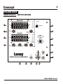
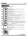
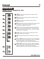
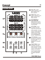
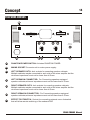
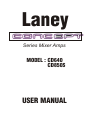
Laney
Series Mixer Amps
MODEL : CD640
CD850S
USER MANUAL
Intended to alert the user to the presence of uninstalled "dangerous voltage" within the product's enclosure
that may be of sufficient magnitude to constitute a risk of electric shock to persons.
Intended to alert the user of the presence of important operating and maintenance (servicing) instructions in
the literature accompanying the product.
Caution: Risk of electrical shock - DO NOT OPEN!
Caution: To reduce the risk of electrical shock, do not remove cover. No user servicable parts inside. Refer servicing to
qualified service personnel.
WARNING: To prevernt electrical shock or fire hazard, do not expose this appliance to rain or moisture. Before using this
appliance, read the operating guide for further warnings.
This apparatus must be earthed.
EMC warning
It is inherent in the design of a loudspeaker and in the design of guitar pickups that they should emit or be affected by electro magnetic fields. Loudspeaker enclosures should not
be used less than two meters away from equipment, which is likely to be affected by electro magnetic interference.
Likewise, guitar fitted with electro magnetic pickups should not be used less than two meters away from any source of emissions such as loudspeakers. Emissions from
loudspeakers are dependent on the frequency characteristics of the drive unit. Levels were measured direct from the driver of 30 dBuV. These levels are reduced to a safe level at
a distance of 1,27 meters from the drivers.
IMPORTANT SAFETY INSTRUCTIONS
WARNING: When using electric products, basic cautions should always be followed, including the following.
1.
2.
3.
4.
5.
6.
7.
8.
9.
10.
11.
12.
13.
14.
15.
16.
17.
Read all safety and operating instructions before using this product
All safety and operating instructions should be retained for future reference
Obey all cautions in the Operating instructions and on the back of the unit
All operating instructions should be followed
This product should not be used near water, i.e. a bathtub, sink, swimming pool, wet basement, etc.
This product should be located so that its position does not interfere with its proper ventilation. It should not be placed
flat against a wall or placed in a built up enclosure that will impede the flow of cooling air.
This product should not be placed near a source of heat such as stove, radiator, or another heat producing amplifier.
Connect only to a power supply of the type marker on the unit adjacent to the power supply cord.
Never break off the ground pin on a power supply cord.
Power supply cords should always be handled carefully. Never walk or place equipment on power supply cords.
Periodically check cords for cuts or signs of stress, especially at the plug and the point where the chord exits the unit.
The power supply cord should be unplugged when the unit is to be unused for long periods of time.
If this product is to be mounted in an equipment rack, rear support should be provided.
Metal parts can be cleaned with a damp cloth. The vinyl covering used on some units can be cleaned with a damp
cloth or ammonia based household cleaner if necessary. Disconnect the unit from the power supply before cleaning.
Care should be taken so that objects do not fall and liquids are not spilled into the unit through any ventilation holes or
openings.
A qualified service technician should check the unit if:
The power cord has been damaged
Anything has fallen or spilled into the unit
The unit does not appear to operate correctly
The unit has been dropped or the enclosure damaged.
The user should not attempt to service the equipment. All service work is done by a qualified service technician.
Exposure to extremely high noise levels may cause a permanent hearing gloss. Individuals very considerably in
susceptibility to noise induced hearing loss, but nearly everyone will lose some hearing if exposed to sufficiently intense
noise for a sufficient time. The U.S. Government's Occupational Safety and Health Administration (OSHA) has
specified the following permissible noise level exposure.
Duration Per Day In Hours
8
6
4
3
2
1½
1
½
¼ or less
Sound Level dBA, slow response
90
92
95
97
100
102
105
110
115
According to OSHA, any exposure in excess of the above permissible limits could result in some hearing loss. Ear plugs or
protectors in the ear canals or over the ears must be worn when operating this amplification system in order to prevent a
permanent hearing loss if exposure exceeds the limits set forth above. To ensure against potentially dangerous exposure to
high sound pressure levels it is recommended that all persons exposed to equipment capable of producing high sound
pressure levels such as this amplification system be protected by hearing protectors while this unit is in operation.
SAVE THESE INSTRUCTIONS
Concept
1
THANK YOU
We at Laney are extremely pleased that you have decided to select a Concept product for
your sound requirements and we wish to reinforce your judgement by ensuring you get
off to a flying start by including this comprehensive user manual to assist you in getting
to know your equipment.
Before switching on please read this manual carefully since, whilst you may well be an
experienced user, no two brands are the same, and on reading this manual you will
become aware of the subtle advantageous differences that Concept offers over its
competitors.
UNPACKING
On unpacking your Concept mixer amp, please check carefully for any signs of damage
that may have occurred whilst in transit from the Laney factory to your dealer. In the unlikely
event that there has been damage, please re-pack your unit in its original carton and
consult your dealer.
We would strongly advise you to store away your original transit carton, since, in the
unlikely event that some time in the future your unit should develop a fault, you will be able
to return it to your dealer for rectification securely packed.
IMPORTANT SAFETY INFORMATION
Your Concept mixer amp should be fitted with a three pin 'grounded' (or 'earthed') plug.
Please make sure that the unit is powered from a 'grounded/earthed' outlet.
If changing or fitting a plug yourself, ensure that the applicable wiring code is adhered to;
for example, in the UK, the cable colour code for connections is as follows:
EARTH OR GROUND
NEUTRAL
LIVE
GREEN/YELLOW
BLUE
BROWN
The Concept product should never be exposed to moisture or wetness under any
circumstances, since this would represent a possible shock or fire hazard, and may cause
expensive damage to your valuable possession.
In the unlikely event that a fuse should blow, it is imperative that you or your engineer, use
a correctly rated replacement.
Details of the fuses required are printed on the back panel of the mixer amp. Please take
special care to use a 'time delay' fuse wherever stated.
CD640 CD850S Manual
Concept
2
FRONT PANEL FEATURES:
CD640
1
-0+
1
2
1
3
4
5
5
1
-0+
4
1
1
-0+
2
3
Bass
4
5
Bass
6
3
4
8
1
4
5
1
4
8
2
1
4
5
1
4
8
1
9
4
8
10
0
4
Level
Pad
Level
Pad
1
2
3
4
Line
Line
Line
Line
4
8
0
6
10
7
10
Main EQ
8
9
10
+15
+3
0
Limiter
Active
0dB
0dB
-5
Main
Bridged
10
0
5
4
6
3
6
8
9
10
0
Line2
5
4
6
3
7
1
Line1
-18
-15
60Hz 160Hz 400Hz 1KHz 2.5KHz 6KHz 16KHz
Master
Volume
FX Out
Level
Line2
6
+15
8
9
2
Line1
5
Master 1
Volume 0
-15
7
1
5
4
2
9
Phantom 48V
-10
2
Level
Off
9
5
3
7
9
On
3
8
10
0
6
1
10
0
Level
Pad
8
1
-5
-10
FX
7
FX
2
9
Level
Pad
9
3
8
1
6
2
10
5
5
4
1
0
9
10
0
8
FX
7
2
9
1
3
6
7
0
Digital
Effects
8
Mon
5
4
3
FX
2
Return 1
6
7
6
7
6
3
7
1
5
5
2
10
0
FX
9
4
5
2
10
0
3
8
6
2
10
0
5
1
Mon
7
60Hz 160Hz 400Hz 1KHz 2.5KHz 6KHz 16KHz
On
5
3
8
6
2
4
Power
-18
-15
3
4
Bass
7
0dB
-15
2
4
6
2
10
5
5
1
3
5
3
9
4
3
9
4
8
9
1
0
10
0
3
7
1
10
0
1
FX
4
8
Mon
8
Bass
7
6
7
6
2
9
5
2
9
5
3
7
1
4
3
4
5
5
-0+
0dB
Small
Hall
2
2
4
Large
Hall
3
4
5
1
+3
0
4
1
3
6
2
9
10
0
10
0
6
3
2
1
3
8
FX
8
Mon
7
5
3
7
6
2
9
10
0
FX
5
3
4
-0+
+15
1
3
5
+15
Vocal
2
Mid
2
3
4
Bass
3
4
1
-0+
1
2
5
5
5
5
1
4
Monitor EQ
3
4
5
5
Treb
3
Mid
2
4
5
-0+
2
4
2
1
3
6
2
9
10
0
Mon
7
5
3
8
6
3
4
7
2
9
10
0
Mon
Bass
-0+
2
3
4
6
3
7
2
5
3
4
1
5
5
1
1
3
4
2
5
5
2
4
1
4
Mid
3
5
-0+
1
2
2
Treb
2
1
3
4
5
5
-0+
-0+
3
4
2
3
4
1
1
4
5
2
-0+
3
4
5
5
5
1
3
Treb
3
4
1
2
2
1
3
Mid
2
3
4
5
5
-0+
1
4
2
1
2
2
4
1
2
4
-0+
5
-0+
3
4
5
5
5
1
3
Treb
3
4
1
2
2
1
3
Mid
1
4
2
1
3
-0+
2
4
5
5
5
5
-0+
3
4
Treb
3
3
Mid
3
4
2
1
2
2
1
2
1
3
4
Treb
-0+
2
2
3
FX
Return
4
8
2
1
9
10
0
5
6
3
7
8
2
Aux In1 0
9
10
5
4
6
4
3
7
7
8
2
Tape In1 0
9
Main
Main
Monitor
Power Amp Mode
6
7
8
2
1
10
9
10
0
Tape Rec
In Out
Laney
Footswitch
5
3
Main
Aux In
Aux In
CD640 PORTABLE POWERED MIXER
Mic
Mic
Mic
Mic
Mic
Mic
Main Out
FX Out
CD850S
1
-0+
1
2
1
2
3
3
4
4
5
5
Treb
1
-0+
Mid
5
1
-0+
1
4
5
5
4
5
4
8
2
1
9
10
0
Mon
4
5
3
4
8
FX
9
1
- 0+
2
3
4
Pan
4
8
5
3
4
8
1
9
0
4
Pan
7
5
3
4
8
1
9
0
4
Pan
7
5
3
Pan
4
7
8
1
9
0
5
3
4
8
1
9
0
4
Pan
7
5
9
0
1
3
4
5
Pan
4
7
8
1
10
9
0
10
3
4
5
9
0
- 0+
10
Level
-5
+15
+15
0dB
0dB
4
2
2
-15
-15
3
4
5
7
8
1
9
0
6
7
8
2
9
10
0
Headphone
6
3
2
5
1
60Hz 160Hz 400Hz 1KHz 2.5KHz 6KHz 16KHz
4
5
10
Level
4
5
6
3
4
7
8
2
1
9
0
10
Level
Pad
Level
Pad
Level
Pad
Level
Pad
Level
Pad
Level
Pad
1
2
3
4
5
6
Line
Line
Line
Line
Line
Line
Left+Mono
Left+Mono
Left Send
Mic
Mic
Mic
Mic
Mic
Mic
Right
Right
Left Return
7-8
-10
3
9-10
Left Master
5
6
3
4
7
8
2
1
9
0
10
Right Master
5
6
3
4
7
8
2
1
9
0
10
Monitor Out
5
Monitor
Right Return Aux In (Stereo)
Program
12 13 14
15
11
16
10
9
1
8
2
7
3
6 5 4
4
5
6
3
7
8
1
7
8
2
9
0
Bank Select
6
3
2
1
10
9
0
Tape/Aux In
CD850S PORTABLE POWERED MIXER
Right Send
Digital
Effects
Dly.M
Dly.S
Room
Hall
-18
1
3
4
8
1
8
9
Pan
7
0
Right EQ
10
0
5
6
3
2
-15
7
1
5
Phantom On 48V
6
3
1
2
4
9
10
5
2
FX
-18
Right Level
+3
60Hz 160Hz 400Hz 1KHz 2.5KHz 6KHz 16KHz
8
1
1
2
5
6
3
- 0+
3
5
2
8
-15
6
2
4
9
0dB
7
0
10
0
5
5
Mon
7
1
FX
2
4
4
8
3
0dB
3
3
6
2
1
2
Pan
7
1
- 0+
5
6
3
10
3
5
2
10
8
9
1
9
5
4
2
4
10
0
7
1
0
1
On
-5
4
5
8
+15
-10
1
4
Bass
7
Mon
-0+
2
3
6
2
6
3
FX
2
4
5
2
1
2
5
6
3
- 0+
3
5
2
10
8
9
1
4
4
10
0
9
10
0
5
4
8
1
5
5
0
+15
5
1
4
3
3
4
Mid
3
Bass
2
Power
Left Level
+3
Left EQ
1
4
5
2
4
-0+
2
3
1
2
6
2
Mon
7
1
5
5
7
6
3
FX
2
4
5
2
1
2
5
6
3
- 0+
3
5
2
10
8
1
9
4
9
4
-0+
1
4
3
5
3
5
1
3
Mid
3
4
5
2
Laney
2
4
Treb
4
1
2
3
1
4
1
4
5
10
0
10
0
1
-0+
-0+
2
3
5
3
Bass
8
2
5
2
6
7
Mon
7
1
5
5
3
6
3
FX
2
4
5
2
1
2
5
6
3
- 0+
3
5
2
10
8
1
9
4
9
4
10
0
10
0
1
4
5
8
1
5
1
3
2
4
5
2
3
3
4
-0+
1
2
Treb
4
1
2
3
1
4
Mid
3
Bass
-0+
2
3
1
4
5
5
2
6
2
Mon
7
1
5
7
6
3
FX
2
4
5
2
1
2
5
6
3
2
- 0+
3
5
5
4
9
1
9
10
0
10
0
4
8
1
5
5
5
2
4
1
3
-0+
4
-0+
1
3
5
2
1
2
Treb
4
3
-0+
2
3
1
4
1
4
3
-0+
2
Mid
3
Bass
5
5
2
4
4
3
1
2
6
2
Mon
7
1
5
7
6
3
FX
2
4
5
2
1
3
9
10
0
10
0
4
8
1
5
5
5
-0+
4
1
3
1
3
5
2
1
2
Treb
4
3
-0+
2
3
1
4
1
4
3
-0+
2
Mid
3
Bass
5
5
2
4
4
3
1
2
6
2
Mon
7
1
5
7
6
2
5
5
5
-0+
4
1
3
1
3
5
2
1
2
Treb
4
3
-0+
2
3
1
4
1
4
3
-0+
2
Mid
3
Bass
7
5
5
2
4
4
3
1
2
6
3
5
-0+
4
1
3
1
3
5
2
1
2
Treb
4
3
-0+
2
3
1
4
Mid
3
Bass
-0+
2
5
2
4
5
3
1
2
3
4
1
3
5
4
5
4
1
3
Treb
2
4
1
2
1
2
3
-0+
2
3
10
FX Level
FX
L Tape In R
L Tape out R
FX Send
Tip=L
Ring=R
FX Return (Stereo)
CD640 CD850S Manual
Concept
3
FEATURES CD640
CD640 Features - Channels 1 - 4
1
-0+
2
1
3
4
4
5
5
1
-0+
3
3
4
5
5
Mid
1
-0+
3
3
4
4
Bass
4
4 MON: Controls the amount of signal sent from the channel
to the ‘Monitor’ output socket, giving the user the
versatility of a separate monitor mix.
5
5
6
3
7
8
2
1
9
10
0
Mon
4
5
5 FX: Controls the amount of signal sent by the individual
channel to the onboard DSP section. The overall level of
effects is controlled via the FX return controls for the Main
and Monitor mix. See below.
6
3
7
8
2
1
9
10
0
FX
4
5
6
3
7
6 LEVEL: Adjusts the channel level, enabling the user to
balance levels across channels.
8
2
1
9
0
7
individual channel.
2
5
6
3 BASS: Adjusts the low frequency response of the
1
2
5
individual channel.
2
4
4
2 MID: Adjusts the mid range frequency response of the
1
2
3
individual channel.
2
3
Treb
2
1 TREBLE: Adjusts the high frequency response of the
1
Level
Pad
10
7 PAD: Reduces the input gain of the channel, allowing the
user to match the input level of the channel with the output
level of the device to be amplified. This is especially useful
when amplifying instruments, mics., processors, etc. with
a very high output level.
1
8 LINE INPUT: Jack input socket, for all line level signals
(Keyboard, Signal Processor, Sampler, Drum Machine,
etc.).
8
Line
9
9
MIC INPUT: XLR input for low impedance microphone
(200-600 Ohm).
Mic
CD640 CD850S Manual
Concept
4
FEATURES CD640
CD640 Features - Channels 5 & 6
1
-0+
2
1
2
4
4
5
5
1
-0+
1
2
2
4
5
5
Mid
1
-0+
3
3
4
4
Bass
4
5
5
6
3
7
4 MON: Controls the amount of signal sent from the channel
to the ‘Monitor’ output socket, giving the user the versatility
of a separate monitor mix.
8
2
1
9
10
0
Mon
4
5
6
3
7
8
2
1
9
4
5 FX: Controls the amount of signal sent by the individual
channel to the onboard DSP section. The overall level of
effects is controlled via the FX return controls for the Main
and Monitor mix. See below.
10
0
FX
5
6
3
6
3 BASS: Adjusts the low frequency response of the
2
5
5
individual channel.
individual channel.
1
2
4
2 MID: Adjusts the mid range frequency response of the
3
3
4
3
individual channel.
3
3
Treb
2
1 TREBLE: Adjusts the high frequency response of the
1
7
8
2
1
6 LEVEL: Adjusts the channel level, enabling the user to
balance levels across channels.
9
0
Level
1
10
9 MIC INPUT: XLR input for low impedance microphone
(200-600 Ohm).
10 DUAL LINE INPUT: Jack input socket, for all line level
signals (Keyboard, Signal Processor, Sampler, Drum
Machine, etc.).
10
Line
9
Mic
CD640 CD850S Manual
Concept
5
FEATURES CD640
CD640 Features - DSP
11 VOCAL: Selects the VOCAL effect from the onboard DSP.
11
to any channel with an FX setting of more than zero.
Overall level of VOCAL DSP is controlled by the FX return
controls for the MONITOR and MAIN power amp sections.
Vocal
12
13
Large
Hall
12 LARGE HALL: Selects the LARGE HALL reverb effect from
Small
Hall
14
the onboard DSP. to any channel with an FX setting of
more than zero. Overall level of LARGE HALL DSP is
controlled by the FX return controls for the MONITOR and
MAIN power amp sections.
On
13 SMALL HALL: Selects the SMALL HALL reverb effect from
Digital
Effects
the onboard DSP. To any channel with an FX setting of
more than zero. Overall level of SMALL HALL DSP is
controlled by the FX return controls for the MONITOR and
MAIN power amp sections.
FX
14 ON: Switches the onboard DSP on.
FX Out
4
5
6
3
15
7
8
2
1
9
0
10
15 FX OUT: The FX mix per channel is also able to be sent to
an external effects device connected to the FX OUT
SOCKET. The overall level of signal sent to the external
effects device is controlled by the FX OUT control. The
return signal form the external effects device should be
connected to the AUX IN.
16 FOOTSWITCH: Allows the remote switching of the
16
onboard DSP, either on or off. Uses a mono footswitch.
Footswitch
17 FX OUT SOCKET: Jack provided for connecting an
external effects device to the amplifier. The level of signal
present at the jack in contorlled by the individual channel
FX controls along with the FX OUT control
17
FX Out
CD640 CD850S Manual
Concept
6
FEATURES CD640
CD640 Features - OUTPUT SECTION
Monitor EQ
+15
+15
+3
Power
0
18
0dB
0dB
-15
4
5
6
3
19
4
8
Main EQ
6
31
8
9
10
+15
0dB
32
Phantom 48V
7
Master 1
Volume 0
+15
20
5
2
9
10
Off
3
7
0
On
-10
-18
-15
60Hz 160Hz 400Hz 1KHz 2.5KHz 6KHz 16KHz
FX
2
Return 1
-5
+3
0dB
0
Limiter
Active
-5
Main
Bridged
30
-10
-15
-18
-15
60Hz 160Hz 400Hz 1KHz 2.5KHz 6KHz 16KHz
4
5
6
3
21
FX
Return
4
7
8
2
1
9
0
10
5
6
3
8
2
Aux In1 0
4
9
10
5
6
3
7
Master
Volume
4
7
8
2
Tape In1 0
9
10
5
6
3
Main
Main
Main
Monitor
Power Amp Mode
7
29
8
2
1
9
10
0
28
Tape Rec
In Out
Laney
Aux In
Aux In
27
CD640 PORTABLE POWERED MIXER
Main Out
22
23
24
25 26
CD640 CD850S Manual
Concept
7
18
MONITOR EQ: 7 band graphic equalizer, for the ‘Monitor/Main’ section of
the amplifier. This also acts as EQ for the line level ‘Monitor’ output socket.
19
FX RETURN: Controls the overall effects level of the on board DSP present in
the monitor signal.
20
MAIN EQ: 7 band graphic equalizer, for the ‘Main’ section of the amplifier.
This also acts as EQ for the line level ‘Main’ output socket.
21
FX RETURN: Controls the overall effects level of the on board DSP present in
the main signal.
22
AUX IN: Determines the overall level of signal connected to the AUX IN jack.
When used with an external effects device this control sets to overall level of
the effects device in the master mix.
23
TAPE IN: Determines the level of an external device connected to the TAPE
IN jacks.
24
AUX IN: Jack socket line in, designed to work in conjunction with the ‘Effect
Out’ socket, as the return of an effects loop.
25
TAPE IN: Dual phono, line level input sockets, ideal for connecting an
external tape machine, CD player, etc. to the amplifier.
26
REC OUT: Dual phono, line level output sockets, ideal for connecting an
external recording device.
27
MAIN OUT: Provides a line level signal for connecting to external power amp
sources. Signal level is determined by the MAIN MASTER VOLUME.
28
MONITOR OUT: Line level signal provided for connecting to an external
powered monitor or connecting to an external power amplier supplying unpowered monitors. The Level of signal present at this socket is determined
by the individual MONITOR level of each channel. With the AMP MODE
SELECTOR set to MAIN/MONITOR the MONITOR OUTPUT SOCKET on
the rear of the amplifier should be used for connecting to unpowered
monitors. A line level signal is always present at this front panel MONITOR
OUT socket.
29
MASTER VOLUME: Sets the overall listening level of the powered mixer.
CD640 CD850S Manual
Concept
8
30
AMP MODE SELECTOR SWITCH: This selects the functions of the two
power amp modules within the unit, whether bridged together as one mono
amp (set switch to ‘Bridge’), running in dual mono mode, as two separate
front-of-house amps (set switch to ‘Main-Main’), or running as two
independent amps, one for the front-of-house mix, and one for the monitors
(set switch to ‘Main-Mon’).
31
MASTER VOLUME: Determines the overall level sent to the monitor out.
32
PHANTOM POWER: 48V phantom power, provided for condenser mics. and
active DI boxes. It is globally switched to all of the mic. inputs, when the
switch is set to ‘48V’. It is vital to ensure that phantom power is switched ‘Off’
when using passive mics., DI boxes, etc., in the mic. inputs, otherwise the
source may be damaged. All connections should be made before switching
phantom power on.
FEATURES CD640
CD640 Features - REAR PANEL
33
34
35
MONITOR BRIDGED
36
37
MAIN OUT
0
Power
CAUTION
RISK OF ELECTRIC SHOCK - DO NOT OPEN
Warning
To reduce the risk of fire or electric shock do not
expose this appliance to rain or moisture.
!
Caution
For continued protection against risk of fire replace
only with same type and rated fuse
32
POWER SWITCH: Activates the unit.
33
MONITOR OUT: This socket should be used to connect an unpowered
monitor when the AMP MODE SWITCH is set to MAIN/MONITOR. Total
monitor impedance must not be lower than 4 Ohms.
34
BRIDGED: Socket for connecting speakers when the AMP MODE SWITCH is
set to BRIDGED MODE. Total impedance should not be less than 8 Ohms.
35
MAIN OUT: Sockets for connecting main front of house speakers.
Minimimum impedance 4 Ohms each side.
CD640 CD850S Manual
Concept
9
FEATURES CD850S
CD850S Features - Channels 1 - 6
1
-0+
1
2
1
2
3
3
4
4
1
-0+
1
2
2
2
3
3
4
5
5
1
-0+
2
2
4
5
5
4
5
6
3
7
8
2
1
10
0
4
5
7
channel to the onboard DSP section.
8
2
1
9
10
0
FX
1
- 0+
6 LEVEL: Adjusts the channel level, enabling the user to
balance levels across channels.
1
2
2
3
3
4
4
5
5
Pan
4
5
6
3
7
8
2
1
9
0
7
to the ‘Monitor’ output socket, giving the user the
versatility of a separate monitor mix.
5 FX: Controls the amount of signal sent by the individual
6
3
6
4 MON: Controls the amount of signal sent from the channel
9
Mon
33
individual channel.
3
4
5
individual channel.
3 BASS: Adjusts the low frequency response of the
1
3
Bass
4
2 MID: Adjusts the mid range frequency response of the
4
Mid
3
individual channel.
5
5
Treb
1 TREBLE: Adjusts the high frequency response of the
Level
Pad
1
10
7 PAD: Reduces the input gain of the channel, allowing the
user to match the input level of the channel with the output
level of the device to be amplified. This is especially useful
when amplifying instruments, mics., processors, etc. with
a very high output level.
8 LINE INPUT: Jack input socket, for all line level signals
(Keyboard, Signal Processor, Sampler, Drum Machine,
etc.).
MIC INPUT: XLR input for low impedance microphone
9 (200-600 Ohm).
8
Line
33 PAN: Determines the position of the input in the stereo
mix.
9
Mic
CD640 CD850S Manual
Concept
10
FEATURES CD850S
CD850S Features - Channels 7/8 - 9/10
-0+
1
1
2
1
2
3
3
4
4
-0+
1
1
2
2
3
3
4
-0+
1
2
2
4
5
5
5
4
6
3
7
1
5 FX: Controls the amount of signal sent by the individual
10
0
5
4
6
3
7
8
2
1
9
10
0
1
- 0+
1
2
2
3
3
4
4
4
channel to the onboard DSP section. The overall level of
effects is controlled via the FX return controls for the Main
and Monitor mix. See below.
6 LEVEL: Adjusts the channel level, enabling the user to
balance levels across channels.
5
5
Pan
5
6
3
6
to the ‘Monitor’ output socket, giving the user the
versatility of a separate monitor mix.
9
Mon
33
4 MON: Controls the amount of signal sent from the channel
8
2
FX
individual channel.
3
4
5
individual channel.
3 BASS: Adjusts the low frequency response of the
1
3
Bass
4
2 MID: Adjusts the mid range frequency response of the
4
5
5
Mid
3
individual channel.
5
5
Treb
2
1 TREBLE: Adjusts the high frequency response of the
7
8
2
1
33
7 PAN: Determines the position of the input in the stereo
mix.
9
0
10
Level
7-8
34 LEFT + MONO: Jack input socket for all line level signals,
where a stereo signal is required this socket if provided for
the left output from a stereo instrument such as
Keyboard, Signal Processor, Sampler, Drum Machine, etc.
RIGHT INPUT: Jack input socket for all line level signals,
35 where a stereo signal is required this socket if provided for
the right output from a stereo instrument such as
Keyboard, Signal Processor, Sampler, Drum Machine, etc
34
Left+Mono
34
Right
CD640 CD850S Manual
Concept
11
FEATURES CD850S
36 LEFT EQ: 7 band
graphic equalizer, for the
LEFT channel of the
Mixer amplifier.
Laney
37 RIGHT EQ: 7 band
Left EQ
36
+15
+15
0dB
0dB
graphic equalizer, for the
Right channel of the
Mixer amplifier.
38 LEFT MASTER &
-15
RIGHT MASTER:
Determines the overall
listening level of the left
and right outputs of the
mixer amplifier.
-15
60Hz 160Hz 400Hz 1KHz 2.5KHz 6KHz 16KHz
Right EQ
37
+15
+15
0dB
0dB
-15
39 LEFT SEND: Socket
-15
60Hz 160Hz 400Hz 1KHz 2.5KHz 6KHz 16KHz
4
5
6
3
38
4
8
2
1
6
8
1
10
9
0
Left Master
4
7
2
9
0
5
3
7
10
Right Master
5
6
3
7
8
2
1
45
9
10
0
Monitor Out
CD850S PORTABLE POWERED MIXER
41 LEFT RETURN: Socket
40
44
39
Left Send
Right Send
Monitor
40
Right Return Aux In (Stereo)
Left Return
41
42
43
providing a line level
signal from the left hand
power amplifier. Can be
used to connect external
graphics and speaker
control systems. Signal
level is determined by
the LEFT MASTER level
provided for connecting
the return signal from an
external device
connected to the LEFT
SEND.
41 RIGHT SEND: Socket
providing a line level
signal from the left hand
power amplifier. Can be
used to connect external
graphics and speaker
control systems.Signal
level is determined by
the RIGHT MASTER
level
CD640 CD850S Manual
Concept
12
FEATURES CD850S
0
LEFT RETURN: Socket
provided for connecting the
return signal from an external
device connected to the LEFT
SEND.
43
AUX IN: Stereo Aux socket.
44
MONITOR OUT: Line level
signal provided for connecting
to an external powered
monitor or connecting to an
external power amplier
supplying un- powered
monitors. The Level of signal
present at this socket is
determined by the individual
MONITOR level of each
channel.
45
DUAL 5 DOT LED: Level
indicator for the left hand
power amplifer.
46
DUAL 5 DOT LED: Level
indicator for the Right hand
power amplifer.
47
HEADPHONE : Sets the overall
listening level for headphones
connected to the headphone
socket.
48
TAPE IN/AUX IN: Sets the
overall level in the mix of any
external devices connected to
the TAPE IN and AUX IN
sockets.
49
HEADPHONE SOCKET:
Socket Provided for conencting
a pair of stereo headphones.
Power
Left Level
+3
45
42
58
On
-5
-10
-18
Phantom On 48V
57
Right Level
+3
46
Digital
Effects
0
Dly.M
Dly.S
Room
Hall
-5
-10
-18
4
5
6
3
47
7
8
2
1
9
10
0
Headphone
4
5
Program
12 13 14
15
11
16
10
9
1
8
2
7
3
6 5 4
4
8
2
1
5
7
8
2
9
1
10
54
9
0
Tape/Aux In
55
6
3
7
0
56
6
3
48
Bank Select
10
FX Level
FX
53
49
L Tape In R
FX Send
Tip=L
Ring=R
50
52
L Tape out R
51
FX Return (Stereo)
CD640 CD850S Manual
Concept
13
50
TAPE IN: Dual phono, line level input sockets, ideal for connecting an
external tape machine, CD player, etc. to the amplifier.
51
TAPE OUT:Dual phono, line level output sockets, ideal for connecting an
external recording device.
52
FX RETURN: Stereo socket for output of external effects processing devices
connected to FX send.
53
FX SEND: Socket for connecting external effects devices. The level of each
individual channel signal present at this socket is determined by the
individual channels FX level setting. Line level signal.
54
FX Level: Controls the overall effects level on the on board DSP. The level of
effects for each individual channel is determined by the individual channels
FX level setting.
55
DSP PROGRAM SELECTOR: Selects the desired program from the on
board DSP.
56
BANK SELECT: Selects the type of on board DSP effect.
57
PHANTOM POWER LED: 48V phantom power, provided for condenser mics.
and active DI boxes. It is globally switched to all of the mic. inputs, when the
switch is set to ‘48V’. It is vital to ensure that phantom power is switched ‘Off’
when using passive mics., DI boxes, etc., in the mic. inputs, otherwise the
source may be damaged. All connections should be made before switching
phantom power on. Switch located on rear panel.
58
POWER SWITCH: Powers up the unit.
CD640 CD850S Manual
Concept
14
FEATURES CD850S
59
PHANTOM
POWER
+48V
CAUTION
RISK OF ELECTRIC SHOCK - DO NOT OPEN
Warning
To reduce the risk of fire or electric shock do not
expose this appliance to rain or moisture.
CAUTION
RISK OF ELECTRIC SHOCK - DO NOT OPEN
!
Warning
To reduce the risk of fire or electric shock do not
expose this appliance to rain or moisture.
!
Caution
For continued protection against risk of fire replace
Caution
For continued protection against risk of fire replace
only with same type and rated fuse
only with same type and rated fuse
RIGHT
LEFT
4 ohm
200W
4 ohm
200W
EFFECT
FOOT SW
60
61 62
63 64
65
59
PHANTOM POWER SWITCH: Activates PHANTOM POWER.
60
MAINS SOCKET: Connects unit to mains power supply.
61
LEFT SPEAKER OUTS: Jack sockets for conecting speaker cabinets.
Multiple cabinets maybe connected to each side of the mixer amplifer but the
minimum impedance must not be lower than 4 Ohms.
62
LEFT SPEAKON CONNECTOR: For Connecting speakon equipped
speaker cabinets,minimum impedance must not be lower than 4 Ohms.
63
RIGHT SPEAKER OUTS: Jack sockets for conecting speaker cabinets.
Multiple cabinets maybe connected to each side of the mixer amplifer but the
minimum impedance must not be lower than 4 Ohms.
64
RIGHT SPEAKON CONNECTOR: For Connecting speakon equipped
speaker cabinets,minimum impedance must not be lower than 4 Ohms.
65
EFFECT FOOTSWITCH: Socket for connecting external mono footswitch
that will allow remote switching of the onboard DSP.
CD640 CD850S Manual
BLT Industries Ltd.,
Newlyn Road,
Cradley Heath,
West Midlands.
B64 6BE.
Tel: (0044) (0)1384 633821
Fax: (0044) (0)1384 639186
Web site: http://www.laney.co.uk
In the interest of continued product development BLT Industries Ltd. reserves the
right to amend product specification without prior notification.