1
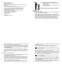
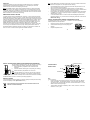
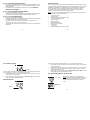
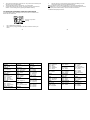
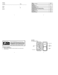
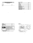
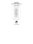
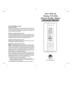
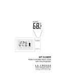
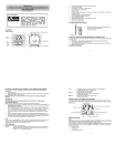
WIRELESS 915 MHz TEMPERATURE STATION Instruction Manual Contents Language Page ___________________________________________________________ TABLE OF CONTENTS Topic English 2 French 53 Spanish 103 Page Inventory of Contents Features Setting Up WWVB Radio Controlled Time Battery Installation Function Keys LCD Screen and Settings Manual Settings Alarm setting Weather Forecast and Tendency Display of Temperature and Humidity Readings Sunrise, sunset, sun duration Moon phases 915 MHz Reception Positioning 1 Care and maintenance Specifications Warranty FCC Disclaimer This product offers: 1. 2. 3. 2 46 47 48 51 INSTANT TRANSMISSION is the state-ofthe-art new wireless transmission technology, exclusively designed and developed by LA CROSSE TECHNOLOGY. INSTANT TRANSMISSION offers you an immediate update (every 4 seconds!) of all your outdoor data measured from the transmitters: follow your climatic variations in real-time! INVENTORY OF CONTENTS Wireless Temperature Station WS-9711U-IT Wireless Temperature Transmitter TX29U-IT Instruction Manual 3 3 4 6 9 10 12 14 18 33 34 38 41 42 43 44 FEATURES: The Weather Station LCD Display Function Keys Battery compartment cover Hanging hole Function Keys WWVB Radio controlled time with manual setting options WWVB Time reception ON/OFF 12/24 hour display Hour, minute and second time display Calendar (weekday, date, month and year) 4 Foldout Stand Time zone option ±12 hours Alarm with snooze function Daylight saving time (DST) function Weather forecasting with 15 easy-to-read weather forecast signs featured by "Weather girl" Weather forecasting icon sensitivity setting Temperature display in Fahrenheit (°F) or degrees Celsius (°C) selectable Indoor and outdoor temperature display with MIN/MAX recording Indoor humidity reading displayed as RH% with MIN/MAX recordings All MIN/MAX temperature recordings show date and time received All MIN/MAX recordings can be reset Display of sunrise time, sunset time and sun duration in 99 cities 12 Moon phases display throughout the year Can take up to three outdoor transmitters LCD contrast setting Low battery indicator LED backlight Table standing/ Wall mounting The Outdoor Temperature Transmitter (TX29U-IT) Note: Sensor must be outside to transmit outdoor temperature. The sensor reads data from the environment it is currently in. SETTING UP: When one transmitter is used 1. First, insert the batteries into the Temperature transmitter (see “Install and replace batteries in the Temperature transmitter“). 2. Immediately after and within 30 seconds, insert the batteries into Weather station (see “Install and replace batteries in the Weather station”). Once the batteries are in place, all segments of the LCD will light up briefly. Next, the time shows 12:00 and the "Weather girl" icon will be displayed. If these are not displayed after 60 seconds, remove the batteries and wait for at least 10 seconds before reinserting them. 3. After inserting the batteries, the Weather station will start receiving data from the transmitter. The outdoor temperature and the signal reception icon should then be 5 4. 5. displayed on the Weather station. If this does not happen after 3 minutes, the batteries will need to be removed from both units and reset from step 1. In order to ensure sufficient 915 MHz transmission however, this should under good conditions be a distance no more than 330 feet (100 meters) in open air between the final position of the Weather Station and the transmitter (see notes on “Positioning” and “915 MHz Reception”). Once the remote temperature has been received and displayed on the Weather station, the WWVB time (radio controlled time) code reception is automatically started. This takes typically between 3-5 minutes in good conditions. If after 10 minutes, the WWVB time has not been received, press the SET key to manually enter a time initially. 6 5. 2. 3. 4. User shall remove all the batteries from the Weather Station and transmitters and wait for 60 seconds if setting has been done with one transmitter before. Insert the batteries to the first transmitter. Within 30 seconds of powering up the first transmitter, insert the batteries to the Weather Station. Once the batteries are in place, all segments of the LCD will light up briefly. Following this, the time (shown as 12:00) and the weather girl icon will be displayed. If they are not shown in the LCD after 60 seconds, remove the batteries and wait for at least 60 seconds before reinserting them. The outdoor temperature from the first transmitter (channel 1) should then be displayed on the Weather station. Also, the signal reception icon will be displayed. If 7 this does not happen after 2 minutes, the batteries will need to be removed from both units and reset from step 1. Insert the batteries to the second transmitter as soon as the outdoor temperature readings from the first transmitter are displayed on the Weather station. Note: User must insert the batteries into the second transmitter within 10 seconds of reception of the first transmitter. 6. 7. When more than one transmitter is used 1. Remote transmission of outdoor temperature to Weather Station by 915 MHz Water resistant casing Wall mounting case (Mounting at a sheltered place. Avoid direct rain and sunshine) The outdoor data from the second transmitter and the "channel 2" icon should then be displayed on the Weather station. If this does not happen after 2 minutes, the batteries will need to be removed from all the units and reset from step 1. Insert the batteries in the third transmitter as soon as the "channel 2" icon and outdoor data are displayed on the Weather station. Within 2 minutes, the channel 3 outdoor data from the third transmitter will be displayed and the channel icon will shift back to "1". If this does not happen, you must restart from step 1. Note: User must insert the batteries into the third transmitter within 10 seconds of reception of the second transmitter. 8. 9. In order to ensure sufficient 915 MHz transmission however, this should under good conditions be a distance no more than 330 feet (100 meters) in open air between the final position of the Weather Station and the transmitter (see notes on “Positioning” and “915 MHz Reception”). Once the remote temperature has been received and displayed on the Weather station, the WWVB time (radio controlled time) code reception is automatically started. This takes typically between 6-8 minutes in good conditions. 8 IMPORTANT: Transmission problems will arise if the setting for additional sensors is not followed as described above. Should transmission problems occur, it is necessary to remove the batteries from all units and start the setup again from step 1. Note: If the WWVB tower icon flashes on the top left of the LCD, but does not set the time or the tower does not appear at all, then please note the following: Note: Daily WWVB reception (Atomic time) is attempted at the top of each hour between 12:00 am to 6:00 am. If the reception is successful, there is no reception attempt until the following day. When this is successful, the received time will override the manually set time. The date is also updated with the received time. (Please also refer to the notes on “WWVB Radio Controlled time” and “Manual Time Setting”) WWVB RADIO CONTROLLED TIME The NIST (National Institute of Standards and Technology – Time and Frequency Division WWVB radio station is located in Ft. Collins, Colorado, and transmits the exact time signal continuously throughout the United States at 60 kHz. The signal can be received up to 2,000 miles away through the internal antenna in the Wireless Weather Station. However, due to the nature of the Earth’s ionosphere, reception is very limited during daylight hours. The Wireless Weather Station will search for a signal every night when reception is best. The WWVB radio station receives the time data from the NIST Atomic clock in Boulder, Colorado. A team of atomic physicists is continually measuring every second, of every day, to an accuracy of ten billionths of a second per day. These physicists have created an international standard, measuring a second as 9.192.631.770 vibrations of a Cesium-133 atom in a vacuum. This atomic clock regulates the WWVB transmitter. Recommended distance from any interfering sources like computer monitors or TV sets is a minimum of 6 feet (2 meters). With ferro-concrete rooms (basements, superstructures), the received signal is naturally weakened. In extreme cases, please place the unit close to a window and/ or point its front or back towards the Fort Collins, Colorado transmitter. During nighttime, the atmospheric disturbances are usually less severe and reception is possible in most cases. A single daily reception is adequate to keep the accuracy deviation below 1 second. In case the Weather Station is not able to detect the WWVB-signal (disturbances, transmitting distance, etc.), the time can be manually set (please refer to the notes on Manual time setting). INSTALL OR REPLACE BATTERIES IN THE WEATHER STATION The Weather Station uses 2 x AA, IEC LR6, 1.5V batteries. To install or replace the batteries, please follow the steps below: 1. 2. 3. Remove the cover at the back of the Weather Station. Insert batteries observing the correct polarity (see marking). Replace compartment cover. 9 10 SNOOZE/ SUN key INSTALL OR REPLACE BATTERIES IN THE TEMPERATURE TRANSMITTER The Temperature Transmitter uses 2 x AA, IEC LR6 and a 1.5V battery. To install or replace the batteries, please follow the steps below: 1. Remove the battery compartment cover at the back of the transmitter. 2. Insert the batteries, observing the correct polarity (see marking). 3. Replace the battery compartment cover on the unit. Note: When changing batteries in any of the units, all units need to be reset by following the setup procedures. This is because a random security code is assigned by the transmitter at start-up and this code must be received and stored by the Weather station in the first 3 minutes of power being supplied to it. BATTERY CHANGE: It is recommended to replace the batteries in all units regularly to ensure optimum accuracy of these units (Battery life See Specifications below). Please participate in the preservation of the environment. Return used batteries to an authorized depot. 11 FUNCTION KEYS: Weather Station: ALM key SET key MIN/ MAX key CH/ + key SET: This key is used to: Enter the set mode for the following functions: LCD contrast, Time zone, Daylight saving time ON/OFF, Time Reception ON/OFF, 12/24 hour display, Manual time, Year, Month, Date, Sunrise/ Sunset city location, Snooze time duration, °F/°C, and Weather forecast sensitivity settings. Toggle between the display of "Weekday + date + month", "Second", "Alarm time", and "Date + month + year". 12 Press and hold for 3 seconds to reset the maximum/ minimum temperature and humidity records of indoor and the currently selected outdoor channel at the same time (will reset all records to current level). Stop the alarm Switch on the backlight MIN/ MAX This key is used to: Toggle between the maximum/ minimum outdoor temperature and maximum/ minimum indoor temperature and humidity data CH/ + key This key is used to: Toggle between the Outdoor transmitters 1, 2 and 3 (if more than 1 transmitter is used) Adjust LCD contrast, time zone, Time Reception ON/OFF, 12/24 hour display, hour, minute, year, month, day, snooze time duration, °F/°C and weather forecasting icon sensitivity in setting modes Adjust the alarm time in alarm setting mode Stop the alarm Switch on the backlight Note: The Time/date shown is corresponding to MIN/MAX temperature data. SNOOZE/ SUN key This key is used to: Activate the snooze function for the alarm Toggle between the sunrise time, sunset time, sun duration in the Sun display Exit manual setting mode and alarm setting mode Switch on the backlight Stop the alarm Switch on the backlight ALM key (alarm) This key is used to: Press for about 3 seconds to enter the Alarm set mode Activate/ deactivate the alarm Stop the alarm Switch on the backlight LCD SCREEN AND SETTINGS: The LCD screen is split into 5 sections displaying the information for time, date, weather forecast, indoors and outdoors. 13 WWVB Tower Icon Alarm icon (for time reception) Daylight saving time 14 Weather Tendency icon indicates whether the last reception was successful (“ON” icon) or not (“OFF” icon). If this icon is blinking, the Temperature Station is currently receiving data. Weather station low battery icon Indoor Temperature Time Relative Humidity in % Calendar Transmitter low battery icon Sunrise/ sunset display Outdoor Temperature Moon phase display Weather Forecast icon (Weather girl) Outdoor Reception Signal* Number showing Transmitter unit Section 1 - TIME AND CALENDAR Normal mode display of radio controlled time. A reception tower symbol will be shown indicating that the WWVB time signal is scanned for (flashing) or received (steady). Note: The symbol will not be shown when radio time reception is not successful or when time reception function is turned off. Display of "Weekday + date + month", "Second", "Alarm time" or "Date + month + year" In normal display, the alarm icon will be shown when the alarm is turned on. Or when the snooze function is activated, the alarm icon will be flashing. Section 2 - Moon phase and Sunrise / Sunset Displays the sunrise, sunset, and sun duration time Displays the 12 different moon phases. *When the signal from the transmitter is successfully received by the Temperature Station, this icon will be switched on. (If not successful, the icon will not be shown on the LCD). This 15 16 Section 3 - WEATHER ICON (WEATHER GIRL) MANUAL SETTINGS: The weather is represented in the form of 15 weather symbols (Weather Girl), which changes appearance depending on the air pressure development and the current outdoor temperature. The weather girl icon representations can be seen in the section "WEATHER FORECAST AND TENDENCY". Section 4 - INDOOR TEMPERATURE AND HUMIDITY Current indoor temperature and humidity. By pressing the MIN/ MAX key, display of the stored MIN/MAX indoor temperature and humidity, with simultaneous display of MIN/ MAX symbol in Section 5. Section 5 - OUTDOOR TEMPERATURE Displays the current outdoor temperature. By pressing the MIN/ MAX key, display of the stored MIN/MAX outdoor temperature with simultaneous display of a MIN or MAX symbol. By pressing the CH/ + key, display of outdoor sensors (up to three outdoor transmitters). The number 1, 2 or 3 will be shown. A signal reception symbol will be shown indicating that receiver is receiving outdoor temperature. To enter the manual setting mode, press and hold the SET key for approximately 3 seconds until the first setting option appears and flashes (LCD contrast setting). From here, each time the SET key is pressed the next available setting option will be selected and will flash to indicate the current option. Once a setting has been made according to the specific instructions that follow, press the SET button once to move the next desired setting or repeatedly until the display returns to normal operating mode. Note: If no buttons are pressed within approximately 15 seconds while in any setting option, the unit will return to normal operating mode. LCD contrast setting Time zone setting Daylight saving time (DST) ON/OFF setting Time reception ON/OFF setting 12/24-Hour setting Manual time setting Manual calendar setting Sunrise/ Sunset city location Snooze setting °F/ °C setting Weather forecasting icon sensitivity setting 17 18 LCD CONTRAST SETTING Flashing The LCD contrast can be set to 8 different levels (0 to 7) to suit the user’s needs (default LCD contrast setting is LCD 5). To set the desired contrast level: 1. Press and hold the SET key until the above display is seen. Press the CH/ + key to select the level of contrast desired. 2. Press the SET key to confirm and enter the “Time Zone setting” or exit the setting mode by pressing the SNOOZE/ SUN key. The time zone default of the Weather Station is -5. To change to another time zone: 1. Press the SET key after completing the LCD contrast setting in order to enter the time zone setting (flashing). 2. Using the CH/ + key, set the time zone. The range runs from 12 to -12 in consecutive 1hour intervals. The U.S. time zones are (negative numbers) -5h (EST), -6h (CST), 7h (MST) and –8h (PST) zones. 3. Press the SET key to confirm and enter the “Daylight Saving Time” (DST) or exit the setting mode by pressing the SNOOZE/ SUN key DAYLIGHT SAVING TIME (DST) ON/OFF SETTING Flashing TIME ZONE SETTING: Note: The DST default is “ON”, meaning that the received time will automatically be adjusted according to Daylight Saving Time in the spring and fall. For areas that do not recognize DST changes turn the DST ‘’OFF’’. Flashing Flashing 19 20 The default is ON for the daylight saving time setting 1. DST starts flashing in the top left black bar and ‘’on” flashing in the bottom left section above the city selection. 2. Use the CH/+ key to toggle between and select on or off. 3. Confirm selection with the SET key and enter the Radio Controlled Time Reception ON/OFF Setting. RADIO CONTROLLED TIME RECEPTION ON/OFF SETTING 2. 3. Use the CH/ + key to turn OFF the time reception function. Confirm with the SET key and enter the “12/24-Hour Display setting” or exit the setting mode by pressing the SNOOZE/ SUN key. Note: If the Time Reception function is turned OFF manually, the clock will not attempt any reception of the WWVB time as long as the Time Reception OFF function is activated. The Time Reception icon will not be displayed on the LCD. 12/24 HOUR TIME DISPLAY SETTING Flashing (time reception icon) Flashing Digit flashing In area where reception of the WWVB time is not possible, the WWVB time reception function can be turned OFF. The clock will then work as a normal Quartz clock (Default setting is ON). 1. The digit “ON” and the time reception icon will start flashing on the LCD. 1. 2. 3. After setting time reception ON/OFF, press the SET key, “12h” or “24h” flashes in the LCD. (default 12h) Press the CH/ + key to select the “12h” or “24h” display mode. Press the SET again to confirm and to enter the “Manual Time setting” or exit the setting mode by pressing the SNOOZE/ SUN key. 21 22 Note: When 24h mode display is selected, the calendar format will be date and month display. When 12h mode display is selected, the calendar format will be month and date display. MANUAL TIME SETTING In case the Weather Station is not able to detect the WWVB-signal (for example due to disturbances, transmitting distance, etc.), the time can be manually set. The clock will then work as a normal Quartz clock. Note: The unit will still try to receive the signal between 12:00 to 6:00 a.m. every day even if the time has been manually set and if the WWVB time reception function has been set ON. When it does receive the signal, it will change the manually set time into the received time. During reception attempts the WWVB tower icon will flash. If reception has been unsuccessful, then the WWVB tower icon will not appear but reception will still be attempted the following hour. CALENDAR SETTING The date default of the Weather Station is 1. 1. of the year 2005 after initial set-up. Once the radiocontrolled time signals are received, the date is automatically updated. However, if the signals are not received, the date can also be set manually. To do this: Minutes (Flashing) Hours (Flashing) To set the clock: 1. The hour digits start flashing in the time display section. 2. Use the CH/ + key to adjust the hours and then press SET key to go to the minute setting. 3. The minute will be flashing. Press the CH/ + key to adjust the minutes. 4. Confirm with the SET key and enter the “Calendar Setting” or exit the setting mode by pressing the SNOOZE/ SUN key. 23 Year "Date. Month." (for 24h time display) "Month. Date." (for 12h time display) 1. 2. Using the CH/ + key, set the year required. The range runs from 2005 to 2029 (default is 2005). Press the SET key to enter the month setting mode. 24 3. 4. 5. The month digit will be flashing. Press the CH/ + key to set the month and then press the SET key to go to the date setting. The date digit will be flashing. Press the CH/ + key to set the date. Confirm with the SET key and enter the “City Setting for Sunrise, Sunset and Sun duration” or exit the setting mode by pressing the SNOOZE / SUN key. 3. Press the SET key to confirm selection and enter the Snooze Setting or exit the manual setting mode by pressing the SNOOZE/ SUN key. Note: City Selection is done in the Program Menu, not by pressing and releasing the SNOOZE button. If your City is not available please choose a city directly North or South of your location (even in different state) for the most accurate sunrise/set time. The US cities are displayed as follows: CITY SELECTION FOR SUNRISE, SUNSET AND SUN DURATION The wireless Weather Station will display the sun rise/ sun set/ or sun duration for 99 selected US and Canada cities: Short form of City location (Flashing) 1. 2. The city abbreviation starts flashing. Use the CH/+ key to toggle through the 99 cities and select cit closest to your location. 25 State, Code – City Alabama MGM – Montgomery MOB – Mobile Arkansas LIT – Little Rock Arizona PHX – Phoenix California FAT – Fresno LAS – Los Angeles ROD – Redding SAN – San Diego SFO – San Francisco Colorado DEN – Denver DRO – Durango GUT – Grand Junction PUB – Pueblo District of Columbia DCA – Washington D.C. State, Code – City Kentucky LEX – Lexington Louisiana NEW – New Orleans SHV – Shreveport Massachusetts BOS – Boston Maine AUG – Augusta CAR – Caribou Michigan DET – Detroit PZQ – Rogers city Minnesota DLH – Duluth INL – International Falls Missouri JEF – Jefferson City 27 26 State, Code – City Oklahoma OKC – Oklahoma City TUL – Tulsa Oregon MFR – Medford PDX – Portland Pennsylvania CXY – Harrisburg PIT – Pittsburgh SCR – Scranton South Carolina CHS – Charleston CUB – Columbia South Dakota FSD – Sioux Falls RAP – Rapid City Tennessee MEM – Memphis BNA – Nashville DKX – Knoxville Florida JAX – Jacksonville MIA – Miami ORL – Orlando TLH – Tallahassee TPA – Tampa Georgia ATL – Atlanta Hawaii HNL – Honolulu Iowa DSM – Des Moines DVN – Davenport Idaho BOI – Boise Illinois ORD –Chicago SPI – Springfield Mississippi JAN – Jackson Montana BIL – Billings HLN – Helena North Carolina CLT – Charlotte RDU – Raleigh North Dakota BIS – Bismarck FAR – Fargo Nebraska LNK – Lincoln SNY – Sidney New Hampshire CON – Concord New Jersey TTN – Trenton 28 Texas AMA – Amarillo AIN – Austin BRO – Brownsville DFW – Dallas/Ft. Worth ELP – El Paso HOU – Houston ODO – Odessa SAT – San Antonio Utah SLC – Salt Lake City Virginia LYH – Lynchburg ORF – Norfolk Vermont BTV – Burlington Washington SEA – Seattle SFF – Spokane Indiana EVV – Evansville IND – Indianapolis Kansas DDC – Dodge City K32 – Wichita TOP – Topeka New Mexico ABQ – Albuquerque Nevada LAS – Las Vegas RNO – Reno SNOOZE SETTING: New York BUF – Buffalo JFK – New York City SYR – Syracuse Wisconsin GBR – Green Bay LSE – La Crosse Ohio CLE – Cleveland CMH – Columbus Wyoming CPR – Casper The Canadian cities are displayed as follows: Code – City ALB – Calgary OTT – Ottawa Code – City QUE – Quebec TOR – Toronto Flashing West Virginia CRW – Charleston Code – City Van – Vancouver WIN – Winnipeg The snooze time can be set OFF or to a maximum time of 30 minutes (default is 10 minutes): 1. The snooze time (in minutes) digit will be flashing. Use the CH/ + key to set the snooze time (in minutes). Each pressing of the key will increase the snooze time by 5 minutes. The snooze can also be set OFF when the “OFF” digit is being displayed. 2. Confirm with the SET key and enter the “ºF/ºC temperature unit setting” or exit the manual setting mode by pressing the SNOOZE/ SUN key. Note: If the snooze time has been set “OFF”, the snooze function will not be activated. 29 30 Flashing °F/°C TEMPERATURE UNIT SETTING pm Flashing Flashing The default temperature reading is set to °F (degree Fahrenheit). To select °C (degree Celsius): 1. The “°F” will be flashing, use the CH/ + key to toggle between “°F” and “°C”. 2. Once the desired temperature unit has been chosen, confirm with the SET key and enter the “Weather Forecast Icon Sensitivity setting” or exit the setting mode by pressing the SNOOZE/ SUN key. WEATHER FORECASTING ICON SENSITIVITY SETTING For locations with rapid changes of weather conditions, the threshold can be set to a different level for faster display of changing weather conditions. 1. 2. 3. 31 The current sensitivity value will start flashing. Using the CH/ + key to set the weather sensitivity level. There are 3 levels of setting: 1, 2 and 3; level 1 is the most sensitive setting, level 3 is the least sensitive setting (default setting is "2"). Confirm with the SET key and exit the Manual settings. 32 ALARM SETTING: SNOOZE SETTING AND STOPPING THE ALARM: Alarm icon flashing 1. 2. When the alarm is sounding, press the SNOOZE/ SUN key to activate the snooze function. The alarm will stop and re-activate after the time interval of the snooze time pre-set by user. To stop the alarm completely, press any keys other than the SNOOZE/ SUN key. WEATHER FORECAST AND TENDENCY: Flashing The weather forecast icons (Weather girl): To set alarm: 1. Press and hold ALM for about 3 seconds until the alarm time display flashes. 2. The hour digit and the alarm icon will be flashing. Press the CH/ + key to adjust the hour. 3. Press ALM button once and minute digit will be flashing. User shall then press CH/ + button to set the minute. 4. Press ALM button once to confirm the setting. 5. To activate/ deactivate the alarm function, press the ALM button once. The display of the alarm icon represents that the alarm is "ON". One of the 15 different weather icons (featured by Weather girl with different clothing) is displayed in the centre of LCD, which indicates the different forecast weather condition due to air pressure level (Sunny, Sunny + Cloudy or Cloudy + Rainy) and the current outdoor temperature (Temperature value detected by Channel 1): 78.8F 66.2 – 78.6F 50 – 66F 32 – 49.8F < 32F Sunny Note: The duration of alarm sounding is 120 seconds 33 78.8F 66.2 – 78.6F 34 50 – 66F 32 – 49.8F < 32F Sunny + Cloudy For every sudden or significant change in the air pressure, the weather icons will update accordingly to represent the change in weather. If the icons do not change, then it means either the air pressure has not changed or the change has been too slow for the Weather Station to register. However, if the icon displayed is a sun or raining cloud, there will be no change of icon if the weather gets any better (with sunny icon) or worse (with rainy icon) since the icons are already at their extremes. The icons displayed forecasts the weather in terms of getting better or worse and not necessarily sunny or rainy as each icon indicates. For example, if the current weather is cloudy and the rainy icon is displayed, it does not mean that the product is faulty because it is not raining. It simply means that the air pressure has dropped and the weather is expected to get worse but not necessarily rainy. 78.8F 66.2 – 78.6F 50 – 66F Cloudy + Rainy 32 – 49.8F < 32F Note: After setting up, readings for weather forecasts should be disregarded for the next 4860 hours. This will allow sufficient time for the Weather Station to collect air pressure data at a constant altitude and therefore result in a more accurate forecast. Common to weather forecasting, absolute accuracy cannot be guaranteed. The weather forecasting feature is estimated to have an accuracy level of about 75% due to the varying areas the Weather Station has been designed for use in. In areas that experience sudden changes in weather (for example from sunny to rain), the Weather Station will be more accurate compared to use in areas where the weather is stagnant most of the time (for example mostly sunny). 35 36 If the Weather Station is moved to another location significantly higher or lower than its initial standing point (for example from the ground floor to the upper floors of a house), remove the batteries and re-insert them after about 30 seconds. By doing this, the Weather Station will not mistake the new location as being a possible change in air-pressure when really it is due to the slight change of altitude. Again, disregard weather forecasts for the next 48-60 hours as this will allow time for operation at a constant altitude. DISPLAY OF TEMPERATURE AND HUMIDITY READINGS: INDOOR TEMPERATURE The indoor temperature and humidity are measured automatically and displayed on the fourth section of the LCD. Indoor Temperature in °F THE WEATHER TENDENCY INDICATOR Working together with the weather icons are the weather tendency indicators (the upward and downward arrow located near the Weather girl). When the indicator points upwards, it means that the air-pressure is increasing and the weather is expected to improve, but when indicator points downwards, the air-pressure is dropping and the weather is expected to become worse. Therefore, user may see how the weather has changed and is expected to change. For example, if the indicator is pointing downwards together with cloudy icons, it means that the last noticeable change in the weather was when it was sunny (the sunny icon only). Therefore, the next change in the weather will be the cloudy icons since the indicator is pointing downwards. Indoor Relative Humidity % OUTDOOR TEMPERATURE: The last LCD section shows the outdoor temperature, a reception symbol and a channel number under the temperature will also show if more than one transmitter has been used. Outdoor Reception Symbol Note: Once the weather tendency indicator has registered a change in air pressure, it will remain permanently visualized on the LCD. Outdoor temperature in F Maximum icon Transmitter Identification No. (only shown when more than one transmitter is used) 37 38 DISPLAY OF INDOOR MAXIMUM AND MINIMUM RECORDS: RESETTING THE OUTDOOR MAXIMUM/ MINIMUM RECORDS 1. Note: It is required to reset the outdoor MAX/MIN temperature records of different channels separately. 2. In normal display mode, press the MIN/ MAX button three times. The maximum indoor temperature and humidity will be shown. Also the date and time of recording this temperature will be displayed. Press the MIN/ MAX button once more to display the minimum indoor temperature and humidity. Also the date and time of recording this temperature will be displayed. 1. In normal display mode, press the CH/ + button to select a channel (1, 2 or 3). The channel ID will be displayed above the outdoor temperature reading. Note: The transmitter number will only be displayed if more than one transmitter is applied. RESETTING THE INDOOR MAXIMUM/ MINIMUM RECORDS 1. 2. In normal display mode, press the MIN/ MAX button to advance to the MIN/ MAX display. Press and hold the SET key for about 3 seconds; this will reset all indoor minimum and maximum data recorded to the current time, date, temperature and humidity. The max/ min temperature of the currently selected outdoor channel will also be reset at the same time. DISPLAY OF OUTDOOR MAXIMUM AND MINIMUM RECORDS: 1. 2. 3. In normal display mode, press the CH/ + button to select the desired channel. The channel ID will be displayed above the outdoor temperature reading. Press the MIN/MAX button, the max temperature of the selected channel will be displayed. Also the date and time of recording this temperature will be displayed. Press the MIN/MAX button once more, the min temperature of the selected channel will be shown. Press the ALM button to go back to the normal display mode. 39 2. 3. Press the MIN/ MAX button once. The max icon will be displayed. Press and hold the SET button for about 3 seconds; this will reset all outdoor minimum and maximum temperature recorded to the current time, date and temperature. Note: The max/ min temperature records of the indoor channel will also be reset at the same time. SUNRISE/ SUNSET/ SUN DURATION TIME: Sunrise time/ Sunset time/ Sun duration time Sunrise/ sunset display Short form of City name (For example, JFK - New York) 40 Press the SNOOZE/ SUN key to toggle between the sunrise, sunset, and sun duration time: Sunrise time Sunrise icon Sunrise time Sunset time THE MOON PHASE The Moon icon of the Weather Station will also display 12 different Moon phases according to the set calendar. Note: In the southern hemisphere, the phases of the moon are same but the shape of the moon is mirror inverted. Full Moon Sunset icon Large Waning Gibbous Small Waning Gibbous Last Quarter Large Waning Crescent Small Waning Crescent Sunset time New Moon Sun duration time (total number of hours of sunlight on the day) Sun duration time icon Sun duration time (hh:mm) Small Waxing Crescent Large Waxing Crescent TEMPERATURE TRANSMITTER: 915 MHz RECEPTION If the outdoor temperature data is not being received within 5 minutes after setting up (the display shows ‘’ - -. - F’’ on the outdoor section for a long time during normal operation) please Small Waxing Gibbous Large Waxing Gibbous LED BACK-LIGHT The LED back-light will be automatically switched ON when any key is pressed. The LED back-light will be switched on for approximately 9 seconds before automatically switching OFF. 41 The range of the Temperature transmitter may be affected by the temperature. At cold temperatures the transmitting distance may be decreased. Please bear this in mind when placing the transmitter. First Quarter 42 The transmission range is about 330 feet (100 m) from the transmitter to the Weather Station (in open space). However, this depends on the surrounding environment and interference levels. If no reception is possible despite the observation of these factors, all system units have to be reset (see Setting up). Note: Sensor must be outside to transmit outdoor temperature. The sensor reads data from the environment it is currently in. check the following items: 1. 2. 3. 4. The distance of the Weather Station or transmitter should be at least 5 to 6.5 feet away from any interfering sources such as computer monitors or TV sets. Avoid positioning the Weather Station onto or in the immediate proximity of metal window frames. Using other electrical products such as headphones or speakers operating on the same signal frequency (915MHz) may prevent correct signal transmission and reception. Neighbors using electrical devices operating on the 915MHz signal frequency can also cause interference. POSITIONING TEMPERATURE TRANSMITTER: The Transmitter is supplied with a holder that may be attached to a wall with the two screws supplied. The Transmitter can also be position on a flat surface by securing the stand to the bottom to the Transmitter. Note: When the 915MHz signal is received correctly, do not re-open the battery cover of either the transmitter or Weather Station, as the batteries may spring free from the contacts and force a false reset. Should this happen accidentally then reset all units (see Setting up above) otherwise transmission problems may occur. 43 44 To wall mount: 1. Secure the bracket onto a desired wall using the screws and plastic anchors. 2. Clip the remote temperature sensor onto the bracket. Note: Before permanently fixing the transmitter wall base, place all units in the desired locations to check that the outdoor temperature reading is receivable. In event that the signal is not received, relocate the transmitters or move them slightly as this may help the signal reception. POSITIONING THE WEATHER STATION: The Weather Station comes complete with a foldout stand that gives the option of table standing or wall mounting. To wall mount: 1. Fix a screw into the desired wall, leaving the head extended out about 0.2” (5mm). 2. Using the Weather Station’s hanging hole, carefully hang it onto the screw. CARE AND MAINTENANCE: Extreme temperatures, vibration and shock should be avoided as these may cause damage to the unit and give inaccurate forecasts and readings. Precautions shall be taken when handling the batteries. Injuries, burns, or property damage may be resulted if the batteries are in contact with conducting materials, heat, corrosive materials or explosives. The batteries shall be taken out from the unit before the product is to be stored for a long period of time. Immediately remove all low powered batteries to avoid leakage and damage. Replace only with new batteries of the recommended type. When cleaning the display and casings, use a soft damp cloth only. Do not use solvents or scouring agents as they may mark the LCD and casings. Do not submerge the unit in water. Special care shall be taken when handling a damaged LCD display. The liquid crystals can be harmful to user's health. Do not make any repair attempts to the unit. Return them to their original point of purchase for repair by a qualified engineer. Opening and tampering with the unit may invalidate their guarantee. Never touch the exposed electronic circuit of the device as there is a danger of electric shock should it becomes exposed. Do not expose the units to extreme and sudden temperature changes, this may lead to rapid changes in forecasts and readings and thereby reduce their accuracy. Note: Always ensures that the unit locks onto the screw head before releasing. 45 46 SPECIFICATIONS: LIABILITY DISCLAIMER Temperature measuring range: Indoor : 14.1°F to +139.8°F with 0.2°F resolution (-9.9ºC to +59.9ºC with 0.1ºC resolution, “OF.L” displayed if outside this range) Outdoor : -39.8°F to +139.8°F with 0.2°F resolution, (-39.9ºC to +59.9ºC with 0.1ºC resolution, “OF.L” displayed if outside this range) Relative humidity measuring range: Indoor : 1% to 99% with 1% resolution (displays “- -” when lower than 1 %; displays "99" % if higher than 99 %) Indoor temperature checking interval : every 15 seconds Indoor humidity checking interval : every 20 seconds Outdoor temperature reception : every 4 seconds Transmission range : up to 330 feet (100 meters) in open air Power consumption: Weather Station Temperature transmitter : : 2 x AA, IEC, LR6, 1.5V 2 x AA, IEC, LR6, 1.5V Battery life cycle (Alkaline batteries recommended) Weather station : Approximately 24 months Temperature transmitter : Approximately 24 months Dimensions (H x L x D) Weather Station Temperature transmitter : : 3.64 x 4.89 x 1.12 inches (92.5 x 124.3 x 28.4 mm) 5.05 x 0.83 x 1.50 inches (128.3 x 38.2 x 21.2 mm) 47 The manufacturer and supplier cannot accept any responsibility for any incorrect readings and any consequences that occur should an inaccurate reading take place. This product is not to be used for medical purposes or for public information. This product is only designed to be used in the home as indication of the future weather and is not 100% accurate. Weather forecasts given by this product should be taken as an indication and not as being totally accurate. The specifications of this product may change without prior notice. This product is not a toy. Keep out of the reach of children. No part of this manual may be reproduced without written consent of the manufacturer. WARRANTY INFORMATION La Crosse Technology ®, Ltd provides a 1-year limited warranty on this product against manufacturing defects in materials and workmanship. This limited warranty begins on the original date of purchase, is valid only on products purchased and used in North America and only to the original purchaser of this product. To receive warranty service, the purchaser must contact La Crosse Technology ®, Ltd for problem determination and service procedures. Warranty service can only be performed by a La Crosse Technology ®, Ltd authorized service center. The original dated bill of sale must be presented upon request as proof of purchase to La Crosse Technology ®, Ltd or La Crosse Technology ®, Ltd’s authorized service center. 48 La Crosse Technology ®, Ltd will repair or replace this product, at our option and at no charge as stipulated herein, with new or reconditioned parts or products if found to be defective during the limited warranty period specified above. All replaced parts and products become the property of La Crosse Technology ®, Ltd and must be returned to La Crosse Technology ®, Ltd. Replacement parts and products assume the remaining original warranty, or ninety (90) days, whichever is longer. La Crosse Technology ®, Ltd will pay all expenses for labor and materials for all repairs covered by this warranty. If necessary repairs are not covered by this warranty, or if a product is examined which is not in need or repair, you will be charged for the repairs or examination. The owner must pay any shipping charges incurred in getting your La Crosse Technology ®, Ltd product to a La Crosse Technology ®, Ltd authorized service center. La Crosse Technology ®, Ltd will pay ground return shipping charges to the owner of the product to a USA address only. Your La Crosse Technology ®, Ltd warranty covers all defects in material and workmanship with the following specified exceptions: (1) damage caused by accident, unreasonable use or neglect (including the lack of reasonable and necessary maintenance); (2) damage occurring during shipment (claims must be presented to the carrier); (3) damage to, or deterioration of, any accessory or decorative surface; (4) damage resulting from failure to follow instructions contained in your owner’s manual; (5) damage resulting from the performance of repairs or alterations by someone other than an authorized La Crosse Technology ®, Ltd authorized service center; (6) units used for other than home use (7) applications and uses that this product was not intended or (8) the products inability to receive a signal due to any source of interference.. This warranty covers only actual defects within the product itself, and does not cover the cost of installation or removal from a fixed 49 FCC DISCLAIMER This device complies with part 15 of the FCC rules. Operation is subject to the following two conditions: (1) This device may not cause harmful interference. (2) This device must accept any interference received, including interference that may cause undesired operation. All rights reserved. This handbook must not be reproduced in any form, even in excerpts, or duplicated or processed using electronic, mechanical or chemical procedures without written permission of the publisher. This handbook may contain mistakes and printing errors. The information in this handbook is regularly checked and corrections made in the next issue. We accept no liability for technical mistakes or printing errors, or their consequences. All trademarks and patents are acknowledged. 51 installation, normal set-up or adjustments, claims based on misrepresentation by the seller or performance variations resulting from installation-related circumstances. LA CROSSE TECHNOLOGY ®, LTD WILL NOT ASSUME LIABILITY FOR INCIDENTAL, CONSEQUENTIAL, PUNITIVE, OR OTHER SIMILAR DAMAGES ASSOCIATED WITH THE OPERATION OR MALFUNCTION OF THIS PRODUCT. THIS PRODUCT IS NOT TO BE USED FOR MEDICAL PURPOSES OR FOR PUBLIC INFORMATION. THIS PRODUCT IS NOT A TOY. KEEP OUT OF CHILDREN’S REACH. This warranty gives you specific legal rights. You may also have other rights specific to your State. Some States do no allow the exclusion of consequential or incidental damages therefore the above exclusion of limitation may not apply to you. For warranty work, technical support, or information contact: La Crosse Technology ®, Ltd 2809 Losey Blvd. South La Crosse, WI 54601 Phone: 608.782.1610 Fax: 608.796.1020 To contact Customer Support / Warranty work by email www.lacrossetechnology.com/support/ La Crosse Technology ® on the Web: www.lacrossetechnology.com 50