1
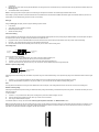
Wireless Weather Station
Instruction Manual
Congratulations on purchasing this state-of-the-art Weather Station as an example of fine design and quality piece of engineering. The operation of this product is simple and
straightforward. By reading this instruction manual, users will receive a better understanding of the Weather Station together with the optimum benefit of all its features.
The Weather Station
Hanging Hole
LCD
Display
Battery
compartment
RESET
key
Function keys
The Temperature Transmitter
Features of the Weather Station
•
4 digits LCD time display
Holder
•
Current indoor temperature display in degree Fahrenheit
•
Simultaneous minimum and maximum indoor temperature recordings
•
Current relative humidity display with “☺“ Smilling or “ “ Sad face for comfort level
reading.
•
3 weather icons for weather forecasting
•
Weather tendency indicator
•
Relative air pressure inHg with adjustable reading ranges
•
Air pressure history for the past 72 hours (electronic barometer with barometric pressure and trend)
•
Current outdoor temperature display in degree Fahrenheit
•
Simultaneous minimum and maximum outdoor temperature recordings.
•
LCD contrast changeable to 8 different tones
•
Low battery indicator
•
Wall mounting
Features of the Temperature Transmitter:
•
Remotely transmits outdoor temperature at 433MHz to the Weather Station
•
With wall mounting holder
Getting Started
Please follow these steps to ensure that your new Weather Station and Temperature Transmitterwork correctly together:
Remove all pieces from the packaging and place onto a table in front of you.
Check that you have complete:
1.
2.
3.
Weather Station
433MHz temperature transmitter
Sealed pack with 3 screws and double-sided tape for wall mounting the transmitter
Setting up
Battery
compartment
Battery
cover
Battery
cover
SET Key
Battery compartment
+ key
1.
2.
3.
4.
Slide open the battery cover of the transmiter as indicated above.
Checking the correct polarization, insert the 2 x AAA, IEC LR3, 1.5V batteries into the battery compartment.
Replace the cover while ensuring the batteries do not spring free from the contacts as this may cause transmission start up problems.
Within 2 minutes of step 3, checking the correct polarization, insert 2 x AA, IEC LR6, 1.5V battery into the battery
5.
6.
compartment.
Replace the front cover while ensuring that the batteries do not spring free from the contacts as this may cause transmission start up problems (should this happen see
Resetting below)
Your Weather Station is now operational.
Note: For securing the product into place, please see “Positioning the Temperature Transmitter“ and “Positioning the Weather Station“ below.
When setting up, always remember to insert the batteries into the transmitter first as this will start the 433MHz transmission signal for the Weather Station to pick when it is
actived (always ensure batteries being used are new and of correct sizes).
Setting up
Going into Setting up, the display will run through the following sequence modes:
•
•
•
•
LCD contrast
Time setting unit (hour followed by minutes)
Relative air pressure setting
Weather sensitivity setting
LCD contrast setting
There are 8 different LCD contrast tones to suit the hanging level of the Weather Sation (default at Level 5). Simply hang the Weather station in the desired place and adjust
the contrast level so that the LCD digits are sharp and clear from that particular level.
1.
2.
3.
Flip open the front cover of the Weather Station from the slot at the base of the unit and then press and hold the “SET“ key until the “LCD5“ start flashing.
Press the “+“ key to select and go through each of the 8 different contrast tones
Once the desired contrast tone is selected, press the “SET“ key once to move to the time setting mode.
Time setting mode
Hour setting
(flashing)
Minutes setting
(flashing)
The hour digits will now start flashing.
1.
Using the “+“ key, sety the required time in hours. Each press will increase the digits by one.
2.
Once the hours are selected, press the “SET“ key to move into the minutes mode.
3.
Press the “+“ key to set the required time in minutes. Each press will increase the digits by one.
4.
When the time has been set, press the “SET“ key. The LCD will now enter the Relative Air pressure inHg setting mode.
Relative air pressure (inHg) setting
Relative air pressure
(flashing)
Following from the manual setting mode, the Relative air pressure inHg on the LCD will start flashing. The air pressure inHg range can be set between 28.60 to 30.45 inHg as
follow:
1.
2.
Press the “+“ key to change the Relative air pressure setting. Each press or holding the key down will increase the digits by 0.01inHg.
When the desired Relative air pressure is set, press the “SET“ key. The LCD will now enter the Weather sensitivity setting mode.
Note:
The inHg feature is beneficial for user living at various altitudes who want for example, to set readings base at sea level and not from their current surrounding area.
Weather sensitivity setting
Following from the Relative air pressure setting, the Weather sensitivity setting will start flashing in the Relative air pressure inHg section. The Weather sensitivity can be set
between the range of
2-4 hPa as follows:
1.
2.
3.
Press the “+“ key to select the hPa. Each press or holding the key down will increase the digit by one hPa.
When the desired hPa is selected, press the “SET“ key to return to the normal mode.
Now hang the Weather Station into place.
Your Weather Station is now fully set. Please read “Positioning the temperature transmitter“ and “Weather Station“ below.
Note: The hPa setting feature can be used in area where there may be constant changes in air pressure which do not necessarily reflect the changes in the weather. In such
areas for example, the hPa might be set to every 3hPa (millibars) meaning that there will be no change of weather icons if the air pressure does not drop or increase by at
least 3hPa. For areas where the weather is stagnant, the hPa can be set lower.
1.
Temperature in degree Fahrenheit
Smilling / Sad face
icons for comfort
reading
Minimum and maximum indoor
temperature reading
Relative humidity
Weather icons
Weather tendency
indicator
Relative air
pressure inHp
Air pressure history
Outdoor temperature
in degree Fahrenheit
Minimum and maximum
outdoor temperature reading
After inserting the batteries, all the segments on the LCD will light up briefly before displaying the time and all the other modes.
Note:
Please check that the outdoor temperature is received on the LCD. Should the signal not be received, then see Checking for 433MHz reception below.
Indoor temperature reading:
The indoor temperature is displayed underneath the time and will automatically appear after few seconds when the batteries are inserted.
Minimum and maximum indoor temperature recordings:
Underneath the current indoor temperature readings are the minimum and maximum indoor temperature recordings. This feature is useful for displaying the recorded
temperatures of the room where the Weather Station has been placed. When a new temperature low or high is reached, it will be automatically updated and displayed.
Relative humidity reading with comfort level reading (face icons)
The relative humidity with comfort level reading is displayed underneath the indoor temperature. With this feature, users can determine how comfortable the reletive humidity
is within their current surroundings. Again, as with the indoor temperature, the relative humidity reading will automatically be taken once the batteries are inserted.
Working together with relative humidity, the Weather Station will register a comfort level reading by representation of a “☺““Smilling“ face or “ ““Sad“ face. The temperature
range between +68ºF to +78.7ºF and relative humidity range between 45% to 65% will register the “Smilling“ face. The “Sad“ face will appear should either the temperature
or humidity readings be outside these set level and the “Sad“ face represents un uncomfortable one.
When the “ ““Sad“ face appears with the word “DRY“ or “WET“, it means that the relative humidity reading is outside its comfort range. However, “DRY“ or “WET“will not
appear if only the temperature reading is outside its comfort level range. The “ ““Sad“ face and “DRY“ will appear of the relative humidity level is below 45% or “WET“ will
appear if the level is above 65%.
Weather tendency icons
There are 3 weather icons on the fourth line of LCD which can be displayed in any one of the following combinations:
Sunny
Cloudy with sunny
intervals
Rainy
For every sudden or significant change in the air pressure, the weather icons will update accordingly to represent the change in weather. If the icons do not change, then it
means either the air pressure has not changed or the change has been too slow for the Weather station to register. However, if the icon displayed is a sun or raining cloud,
there will be no change of icon if the weather gets any better (with sunny icon) or worse (with rainy icon) since the icons are already at their extremes.
The icons displayed forecasts the weather in terms of getting better or worse and not necessarily sunny or rainy as each icon indicates. For example, if the current weather is
cloudy and the rainy icon is displayed, it does not mean that the product is faulty because it is not raining. It simply means that the air pressure has dropped and the weather
is expected to get worse but not necessarily rainy.
Note:
After setting up, readings for weather forecasts should be disregarded for the next 12-24 hours. This will allow sufficient time for the Weather Station to collect air pressure
data at a constant altitude and therefore result in an more accurate forecast.
Common to weather forecasting, absolute accuracy cannot be guaranteed. The weather forecasting feature is estimated to have an accuracy level of about 75% due to the
varying areas the Weather Station has been designed for use in. In areas that experience sudden changes in weather (for example from sunny to rain), the Weather Station
will be more accurate compared to use in areas where the weather is stagnant most of the time (for example mostly sunny).
If the Weather Station is moved to another location significantly higher or lower than its initial standing point (for example from the ground floor to the upper floors of a house),
remove the batteries from both the Weather Station and transmitter and re-insert them after about 30 seconds. By doing this, the Weather Station will not mistake the new
location as being a possible change in air-pressure when really it is due to the slight change of altitude. Again, disregard weather forecasts for the next 12 to 24 hours as this
will allow time for operation at a constant altitude.
The weather tendency indicator
Working together with the weather icons are the weather tendency indicators (located above and belowthe weather icons). When the indicator points upwards, it means that
the air-pressure is increasing and the weather is expected to improve, but when indicator points downwards, the air-pressure is dropping and the weather is expected to
become worse.
Taking this into account, one can see how the weather has changed and is expected to change. For example, if the indicator is pointing downwards together with cloud and
sun icons, then the last noticeable change in the weather was when it was sunny (the sun icon only). Therefore, the next change in the weather will be the cloud with rain
icons since the indicator is pointing downwards.
Note:
Once the weather tendency indicator has registered a change in air pressure, it will remain permanently visualized on the LCD.
Storm warning indicator:
The downward tendency indicator will flash if the air pressure has dropped by 4 hPa or more in the last 6 hours.
Relative air pressure inHg
Underneath the weather icons is the air pressure reading which is recorded constantly in inHg and the Weather Station displays this reading as the relative air pressure.
Air pressure history (electronic barometer with barometric pressure and trend)
Air pressure over
the last 72 hours
Air pressure scale
(Each bar represents one hPa (millibar); 0.03 inHg (inches of mercury) = 1hPa)
The bar chart indicates the air pressure trend over the last 72 hours in 8 steps, 0, -1, -3, -6, -12, -24, -48 and -72 hours. The bar is plotted at each of the right (0, ±1, ±3, ±5,
and ±7) compares the result. The “0“ in the middle of this scale is equal to the current pressure and each change (±1, ±3, ±5, and ±7) is how high or low in “hPa“ the past
pressure was compared to the current.
If the bars are rising, it means that the weather is getting better due to the increase of air pressure. If the bars go down, it means the air pressure has dropped and the weather
is expected to get worse from the present time “0“.
Note:
For accurate barometric pressure trends, the Weather Station should operate at the same altitude for example, it should not be moved from the ground to the second floor of
the house. Should the unit be moved to a new location, reset both the transmitter and Weather Station as this will prevent the slight change in lication registrering as a
possible change in air pressure.
After the resetting or setting up, weather readings should be discarded for the next 12 to 24 hours as this will allow sufficient time for the Weather Station to operate at a
constant altitude and thus enabling a more accurate reading.
Outdoor temperature reading
The outdoor temperature is displayed underneath the weather icon section. The Weather Station will automatically start scanning for the transmitter’s 433MHz signal after the
batteries are inserted and once received, the outdoor temperature will appear on the LCD.
Minimum and maximum oudoor temperature readings
Underneath the current outdoor temperature, are the outdoor minimum and maximum temperature recordings. When a new temperature low or high is reached, it will be
updated and recorded into the Weather Station memory.
Automatic minimum and maximum indoor and outdoor temperature resetting
The Weather Station is programmed to automatically reset the indoor and outdoor minimum and maximum temperature recordings once a day. The maximum temperatures
are reset at 8:00am and the minimum temperatures at 8:00pm.
Note:
There is also a reset button located on the front of the unit for manual resetting of minimum and maximum temperatures (see Manual resetting temperature below)
Manual resetting of minimum and maximum temperatures
The minimum and maximum temperatures of the Weather Station can also be reset manually anytime by simply pressing the RESET key on front on the unit. Once the
RESET key is pressed, the data updates to the current indoor and outdoor temperatures.
Note:
Although the minimum and maximum temperature have been reset manually during the day, the Weather station will still be programmed to reset all minimum and maximum
temperatures once a day.
Checking for 433MHz reception
The Weather Station will automatically start scanning for the 433MHz signal after the batteries are inserted. If the outdoor temperature is not displayed after about 30 seconds,
then check the following list before resetting the units (see Resetting below):
1.
2.
3.
4.
The distance of the receiver or transmitter should be at least 1.5 to 2 meters away from any interfering sources such as computer monitors or TV sets.
Avoid placing the receiver onto or in the immediate proximity of metal window frames.
Using other electrical products such as headphones or speakers operating on the same signal frequency (433MHz) may prevent correct signal transmission and
reception.
Neighbours using electrical devices operating on the 433MHz signal frequency can also cause interference.
Note:
When the 433MHz signal is received correctly, do not re-open the battery cover of either the transmitter or Temperature station, as the batteries may spring free from the
contacts and force a false reset. Should this happen accidentally then reset all units (see Resetting below) otherwise transmission problems may occur.
The transmission range is around 25 m from the transmitter to the Temperature station (in open space). However, this depends on the surrounding environment and
interference levels. If no reception is possible despite the observation of these factors, all system units have to be reset (see Resetting below).
The transmitter’s transmitting range may be affected by exposure to extreme cold condition (-25°C) for long periods of time due to the nature of Alkaline batteries. Should this
happen, the 433MHz signal may be weakenend and therefore result in a shorter transmitting distances caused by temperature level.
Resetting:
1.
2.
Remove batteries from both the outdoor transmitter and the Temperature station.
Wait at least 30 seconds and then repeat the procedures specified in Setting up (above).
Note:
Always wait at least 30 seconds after removing the batteries before reinserting, otherwise start up and transmission problems may occur. Also, remember when insertting, that
both units have to reset and to always reinsert the batteries to the transmitter first.
Positioning the temperature transmitter:
TheTemperature Transmitter is supplied with a holder that may be attached to a wall with the three screws supplied. To attach to the wall, please follow the steps below:
1.
2.
3.
Mark the wall using a pen through the holes in the holder to obtain the exact drilling position.
Drill holes in the wall at the points marked.
Screw holder onto wall.
There is also double sided tape included with the wall mount. This can be used instead of drilling. Please mount this on a smooth surface instead of
a brick one. The surface can, however, affect the transmission range, for example: if the unit is attached to a piece of metal, it may then either
reduce or increase the transmitting range. For this reason, we recommend not placing the unit on any metal surfaces or in any position where a
large metal surface is in the immediate proximity (garage doors, double glazing etc.). Before securing in place, please ensure that the Temperature Station can receive the
signal from the Temperature Transmitter at the positions that you wish to situate them. The Temperature Transmitter clicks in or out of the holder easily. When inserting or
removing the Temperature Transmitter from the wall holder please hold both units securely.
Positioning the Weather Station:
For wall mounting, please check that the outdoor temperature can be received outdoors from the desired locations. To wall mount:
1.
2.
Fix a screw (not supplied) into the desired wall, leaving the head extended out by about 5mm.
Using the Weather Station’s hanging hole, carefully hang it onto the screw. Remember to ensure that it locks into place before releasing.
Important notes:
•
•
•
Avoid placing the units where they can be exposed to sudden changes in temperatures; i.e. direct sunlight, extreme cold and wet/moist conditions. This will help avoid
any inaccurate readings and any possible damage to the unit.
Should the unit be exposed to extreme and sudden temperature changes, it will lead to rapid changes in its forecast reading and thereby reduce its accuracy.
Should the unit be moved to another location that is significantly higher or lower than its standing point (for example from the ground floor to the first floor of a house),
then either reset the units or discard the readings weather forecasts for the next 12-24 hours. By doing so, this will allow allow sufficient time for the unit to operate at a
constant altitude and thus enabling a more accurate forecest.
Care and Maintenance:
•
•
•
•
•
•
Extreme temperatures, vibration and shock should be avoided as these may cause damage to the unit and give inaccurate forecasts and readings.
When cleaning the display and casing, use a soft damp cloth only. Do not use solvents or scouring agents as they may mark the LCD and casing.
Do not submerge the unit in water.
Immediately remove all low powered batteries to avoid leakage and damage. Replace only with new batteries of the recommended size.
Do make any repairs to the unit. Return it to its original point of purchase for repair by a qualified engineer. Opening and tampering with the unit may invalidate its
guarantee.
Do not expose the unit to extreme and sudden temperature changes, this may lead to rapid changes in forecasts and readings and thereby reduce its accuracy.
Battery Change:
It is recommended to replace the batteries in all units on an annual basis to ensure optimum accuracy of these units.
Please participate in the preservation of the environment. Return used batteries to an authorised depot.
Specifications
Temperature measuring range
Indoor
:
Outdoor
:
+14ºF to+140ºF with 0.2ºF
resolution
(“OFL“ display if outside of this range)
-22ºF to+158ºF with 0.2ºF
resolution
(“OFL“ display if outside of this range)
Relative humidity measuring range: 25% to 95% with 1% resolution
(“--.-” displayed if outside this
range)
Relative air pressure hPa
: 28.69hPa to 30.45hPa
Hekto –Pascal setting (hPa)
: 2hPa to 4hPa
Air pressure history
: for the past 72 hours
(1hPa = 0.03 inch mercury (inHg))
(0, -1, -3, -6, -12, -24, -48, -72)
Temperature checking intervals
Indoor
: 10 seconds
Outdoor to the weather Station
: twice in 10 minutes
Transmitter temperature reading
update
: 30 seconds
Transmitting frequency
: 433MHz
Temperature transmitting range : max. 25 meters
Power souces
Weather Station
: 2 x AA, IEC LR6, 1.5V batteries
Transmitter
: 2 x AAA, IEC LR3, 1.5 V
Batteries
Battery life for both unit
(Alkaline batteries recommended) : approximately 12 months
Dimensions (L X W H)
Weather Station
: 145 x 32 x 400mm
Transmitter
: 59 x 21 x 65mm
Liability Disclaimer
•
•
•
•
•
•
The manufacturer and supplier cannot accept any responsibility for any incorrect readings and any consequences that occur should an inaccurate reading take place.
This product is not to be used for medical purposes or for public information.
This product is only designed to be used in the home as indication of the future weather and is not 100% accurate. Weather forecasts and barometric readings given by
this product should be taken only as an indication and not as being totally accurate.
The specifications of this product may change without prior notice.
This product is not a toy. Keep out of the reach of children.
No part of this manual may be reproduced without written consent of the manufacturer.
WARRANTY INFORMATION
La Crosse Technology, Ltd provides a 1-year limited warranty on this product against manufacturing defects in materials and workmanship.
This limited warranty begins on the original date of purchase, is valid only on products purchased and used in North America and only to the original purchaser of this product.
To receive warranty service, the purchaser must contact La Crosse Technology, Ltd for problem determination and service procedures. Warranty service can only be
performed by a La Crosse Technology, Ltd authorized service center. The original dated bill of sale must be presented upon request as proof of purchase to La Crosse
Technology, Ltd or La Crosse Technology, Ltd’s authorized service center.
La Crosse Technology, Ltd will repair or replace this product, at our option and at no charge as stipulated herein, with new or reconditioned parts or products if found to be
defective during the limited warranty period specified above. All replaced parts and products become the property of La Crosse Technology, Ltd and must be returned to La
Crosse Technology, Ltd. Replacement parts and products assume the remaining original warranty, or ninety (90) days, whichever is longer. La Crosse Technology, Ltd will
pay all expenses for labor and materials for all repairs covered by this warranty. If necessary repairs are not covered by this warranty, or if a product is examined which is not
in need or repair, you will be charged for the repairs or examination. The owner must pay any shipping charges incurred in getting your La Crosse Technology, Ltd product to
a La Crosse Technology, Ltd authorized service center. La Crosse Technology, Ltd will pay ground return shipping charges to the owner of the product to a USA address
only.
Your La Crosse Technology, Ltd warranty covers all defects in material and workmanship with the following specified exceptions: (1) damage caused by accident,
unreasonable use or neglect (including the lack of reasonable and necessary maintenance); (2) damage occurring during shipment (claims must be presented to the carrier);
(3) damage to, or deterioration of, any accessory or decorative surface; (4) damage resulting from failure to follow instructions contained in your owner’s manual; (5) damage
resulting from the performance of repairs or alterations by someone other than an authorized La Crosse Technology, Ltd authorized service center; (6) units used for other
than home use (7) applications and uses that this product was not intended or (8) the products inability to receive a signal due to any source of interference.. This warranty
covers only actual defects within the product itself, and does not cover the cost of installation or removal from a fixed installation, normal set-up or adjustments, claims based
on misrepresentation by the seller or performance variations resulting from installation-related circumstances.
LA CROSSE TECHNOLOGY, LTD WILL NOT ASSUME LIABILITY FOR INCIDENTAL, CONSEQUENTIAL, PUNITIVE, OR OTHER SIMILAR DAMAGES ASSOCIATED
WITH THE OPERATION OR MALFUNCTION OF THIS PRODUCT. THIS PRODUCT IS NOT TO BE USED FOR MEDICAL PURPOSES OR FOR PUBLIC INFORMATION.
THIS PRODUCT IS NOT A TOY. KEEP OUT OF CHILDREN’S REACH.
This warranty gives you specific legal rights. You may also have other rights specific to your State. Some States do no allow the exclusion of consequential or incidental
damages therefore the above exclusion of limitation may not apply to you.
For warranty work, technical support, or information contact:
La Crosse Technology
2809 Losey Blvd. S.
La Crosse, WI 54601
Phone: 608.782.1610
Fax: 608.796.1020
e-mail:
[email protected]
(warranty work)
[email protected]
(information on other products)
web:
www.lacrossetechnology.com
THIS DEVICE COMPLIES WITH PART 15 OF THE FCC RULES.
OPERATION IS SUBJECT TO THE FOLLOWING TWO CONDITIONS:
1.
2.
THIS DEVICE MAY NOT CAUSE HARMFUL INTERFERENCE, AND
THIS DEVICE MUST ACCEPT INTERFERENCE RECEIVED, INCLUDING INTERFERENCE THAT MAY CAUSE UNDESIRED OPERATION.