1
FS-C8008N
FS-C8008DN
Color Laser Printer
FS-C8
FS-C8008N
008N
Operation Guide
Cautions
•
•
To prevent the printer from tipping over, the optional CA-31B caster kit must be installed when the printer is installed
with more than one paper feeder or a duplex unit. For detailed information on the CA-31B caster kit, see page A-11.
Do not block the cooling air in and out vents and the exhaust duct against walls or with other objects. If the flow of
cooling air is blocked, heat will be built up in the printer, and there will be a risk of fire.
Note
Moisture condensation inside the printer can cause blurred printing. When a heavily blured printing occurred, turn printer
power off while the power cable is plugged to power. Then, open the front cover, draw the paper transfer unit fully out, and
draw the primary transfer unit out. Allow approximately 2 hours before use.
Please read the Operation Guide before using the printer. Keep it close to the printer for
easy reference.
The sections of this guide and parts of the printer marked with symbols are safety warnings meant to protect the user,
other individuals and surrounding objects, and ensure correct and safe usage of the printer. The symbols and their
meanings are indicated below.
WARNING: Indicates that serious injury or even death may result from insufficient attention to or incorrect
compliance with the related points.
CAUTION: Indicates that personal injury or mechanical damage may result from insufficient attention to or
incorrect compliance with the related points.
Symbols
The
symbol indicates that the related section includes safety warnings. Specific points of attention are indicated
inside the symbol.
....................[General warning]
....................[Warning of danger of electrical shock]
....................[Warning of high temperature]
The
symbol indicates that the related section includes information on prohibited actions. Specifics of the prohibited
action are indicated inside the symbol.
....................[Warning of prohibited action]
....................[Disassembly prohibited]
The
symbol indicates that the related section includes information on actions which must be performed. Specifics
of the required action are indicated inside the symbol.
....................[Alert of required action]
....................[Remove the power plug from the outlet]
....................[Always connect the printer to an outlet with a ground connection]
Please contact your service representative to order a replacement if the safety warnings in the guide are illegible or if
the guide itself is missing. (fee required)
i
Caution
NO LIABILITY IS ASSUMED FOR ANY DAMAGE CAUSED BY IMPROPER INSTALLATION.
Notice on Software
SOFTWARE USED WITH THIS PRINTER MUST SUPPORT THE PRINTER'S EMULATION MODE. The printer
is factory-set to emulate the PCL. The emulation mode can be changed by following the procedures described in
Chapter 3.
Notice
The information in this guide is subject to change without notification. Additional pages may be inserted in future
editions. The user is asked to excuse any technical inaccuracies or typographical errors in the present edition.
No responsibility is assumed if accidents occur while the user is following the instructions in this guide. No responsibility is assumed for defects in the printer's firmware (contents of its read-only memory).
This guide, any copyrightable subject matter sold or provided with or in connection with the sale of the page printer,
are protected by copyright. All rights are reserved. Copying or other reproduction of all or part of this guide, any
copyrightable subject matter without the prior written consent of Kyocera Mita Corporation is prohibited. Any copies
made of all or part of this guide, any copyrightable subject must contain the same copyright notice as the material from
which the copying is done.
Regarding Tradenames
PRESCRIBE is a registered trademark of Kyocera Corporation. KPDL is trademark of Kyocera Corporation.
Diablo 630 is a product of Xerox Corporation. IBM Proprinter X24E is a product of International Business Machines
Corporation. Epson LQ-850 is a product of Seiko Epson Corporation.
Hewlett-Packard, PCL, and PJL are registered trademarks of Hewlett-Packard Company. Centronics is a trade name
of Centronics Data Computer Inc. PostScript is a registered trademark of Adobe Systems Incorporated. Macintosh is
a registered trademark of Apple Computer, Inc. Microsoft, Windows, and Windows NT are registered trademarks of
Microsoft Corporation. PowerPC and Microdrive are trademarks of International Business Machines Corporation.
CompactFlash is a trademark of SanDisk Corporation. ENERGY STAR is a U.S. registered mark. All other brand and
product names are registered trademarks or trademarks of their respective companies.
This Kyocera Mita page printer uses PeerlessPrintXL to provide the HP LaserJet compatible PCL 6 language emulation. PeerlessPrintXL is a trademark of The Peerless Group, Redondo Beach, CA 90278, U.S.A.
This product was developed using the Tornado™ Real Time Operating System and Tools from Wind River Systems.
This product contains UFST™ and MicroType® from Agfa Monotype Corporation.
ii
IBM PROGRAM LICENSE AGREEMENT
THE DEVICE YOU HAVE PURCHASED CONTAINS ONE OR MORE SOFTWARE PROGRAMS ("PROGRAMS") WHICH BELONG TO INTERNATIONAL BUSINESS MACHINES CORPORATION ("IBM"). THIS
DOCUMENT DEFINES THE TERMS AND CONDITIONS UNDER WHICH THE SOFTWARE IS BEING
LICENSED TO YOU BY IBM. IF YOU DO NOT AGREE WITH THE TERMS AND CONDITIONS OF THIS
LICENSE, THEN WITHIN 14 DAYS AFTER YOUR ACQUISITION OF THE DEVICE YOU MAY RETURN THE
DEVICE FOR A FULL REFUND. IF YOU DO NOT SO RETURN THE DEVICE WITHIN THE 14 DAYS, THEN
YOU WILL BE ASSUMED TO HAVE AGREED TO THESE TERMS AND CONDITIONS.
The Programs are licensed not sold. IBM, or the applicable IBM country organization, grants you a license for the
Programs only in the country where you acquired the Programs. You obtain no rights other than those granted you under
this license.
The term "Programs" means the original and all whole or partial copies of it, including modified copies or portions
merged into other programs. IBM retains title to the Programs. IBM owns, or has licensed from the owner, copyrights
in the Programs.
1. License
Under this license, you may use the Programs only with the device on which they are installed and transfer possession
of the Programs and the device to another party.
If you transfer the Programs, you must transfer a copy of this license and any other documentation to the other party.
Your license is then terminated. The other party agrees to these terms and conditions by its first use of the Program.
You may not:
1) use, copy, modify, merge, or transfer copies of the Program except as provided in this license;
2) reverse assemble or reverse compile the Program; or
3) sublicense, rent, lease, or assign the Program.
2. Limited Warranty
The Programs are provided "AS IS."
THERE ARE NO OTHER WARRANTIES COVERING THE PROGRAMS (OR CONDITIONS), EXPRESS OR
IMPLIED, INCLUDING, BUT NOT LIMITED TO, THE IMPLIED WARRANTIES OF MERCHANTABILITY
AND FITNESS FOR A PARTICULAR PURPOSE.
Some jurisdictions do not allow the exclusion of implied warranties, so the above exclusion may not apply to you.
3. Limitation of Remedies
IBM's entire liability under this license is the following;
1) For any claim (including fundamental breach), in any form, related in any way to this license, IBM's liability will
be for actual damages only and will be limited to the greater of:
a) the equivalent of U.S. $25,000 in your local currency; or
b) IBM's then generally available license fee for the Program
This limitation will not apply to claims for bodily injury or damages to real or tangible personal property for which IBM
is legally liable.
IBM will not be liable for any lost profits, lost savings, or any incidental damages or other economic consequential
damages, even if IBM, or its authorized supplier, has been advised of the possibility of such damages. IBM will not be
liable for any damages claimed by you based on any third party claim. This limitation of remedies also applies to any
developer of Programs supplied to IBM. IBM's and the developer's limitations of remedies are not cumulative. Such
developer is an intended beneficiary of this Section. Some jurisdictions do not allow these limitations or exclusions,
so they may not apply to you.
4. General
You may terminate your license at any time. IBM may terminate your license if you fail to comply with the terms and
conditions of this license. In either event, you must destroy all your copies of the Program. You are responsible for
payment of any taxes, including personal property taxes, resulting from this license. Neither party may bring an action,
regardless of form, more than two years after the cause of action arose. If you acquired the Program in the United States,
this license is governed by the laws of the State of New York. If you acquired the Program in Canada, this license is
governed by the laws of the Province of Ontario. Otherwise, this license is governed by the laws of the country in which
you acquired the Program.
Typeface Trademark Acknowledgement
All resident fonts in this printer are licensed from Agfa Corporation.
Helvetica, Palatino and Times are registered trademarks of Linotype-Hell AG. ITC Avant Garde Gothic, ITC
Bookman, ITC ZapfChancery and ITC Zapf Dingbats are registered trademarks of International Typeface Corporation.
iii
Agfa Monotype License Agreement
1) "Software" shall mean the digitally encoded, machine readable, scalable outline data as encoded in a special
format as well as the UFST Software.
2) You agree to accept a non-exclusive license to use the Software to reproduce and display weights, styles and
versions of letters, numerals, characters and symbols ("Typefaces") solely for your own customary business or
personal purposes at the address stated on the registration card you return to Agfa Japan. Under the terms of this
License Agreement, you have the right to use the Fonts on up to three printers. If you need to have access to the
fonts on more than three printers, you need to acquire a multi-user license agreement which can be obtained from
Agfa Japan. Agfa Japan retains all rights, title and interest to the Software and Typefaces and no rights are granted
to you other than a License to use the Software on the terms expressly set forth in this Agreement.
3) To protect proprietary rights of Agfa Japan, you agree to maintain the Software and other proprietary information
concerning the Typefaces in strict confidence and to establish reasonable procedures regulating access to and use
of the Software and Typefaces.
4) You agree not to duplicate or copy the Software or Typefaces, except that you may make one backup copy. You
agree that any such copy shall contain the same proprietary notices as those appearing on the original.
5) This License shall continue until the last use of the Software and Typefaces, unless sooner terminated. This License
may be terminated by Agfa Japan if you fail to comply with the terms of this License and such failure is not
remedied within thirty (30) days after notice from Agfa Japan. When this License expires or is terminated, you
shall either return to Agfa Japan or destroy all copies of the Software and Typefaces and documentation as
requested.
6) You agree that you will not modify, alter, disassemble, decrypt, reverse engineer or decompile the Software.
7) Agfa Japan warrants that for ninety (90) days after delivery, the Software will perform in accordance with Agfa
Japan-published specifications, and the diskette will be free from defects in material and workmanship. Agfa
Japan does not warrant that the Software is free from all bugs, errors and omissions.
THE PARTIES AGREE THAT ALL OTHER WARRANTIES, EXPRESSED OR IMPLIED, INCLUDING
WARRANTIES OF FITNESS FOR A PARTICULAR PURPOSE AND MERCHANTABILITY, ARE
EXCLUDED.
8) Your exclusive remedy and the sole liability of Agfa Japan in connection with the Software and Typefaces is repair
or replacement of defective parts, upon their return to Agfa Japan.
IN NO EVENT WILL AGFA JAPAN BE LIABLE FOR LOST PROFITS, LOST DATA, OR ANY OTHER
INCIDENTAL OR CONSEQUENTIAL DAMAGES, OR ANY DAMAGES CAUSED BY ABUSE OR MISAPPLICATION OF THE SOFTWARE AND TYPEFACES.
9) New York, U.S.A. law governs this Agreement.
10) You shall not sublicense, sell, lease, or otherwise transfer the Software and/or Typefaces without the prior written
consent of Agfa Japan.
11) Use, duplication or disclosure by the Government is subject to restrictions as set forth in the Rights in Technical
Data and Computer Software clause at FAR 252-227-7013, subdivision (b)(3)(ii) or subparagraph (c)(1)(ii), as
appropriate. Further use, duplication or disclosure is subject to restrictions applicable to restricted rights software
as set forth in FAR 52.227-19 (c)(2).
12) YOU ACKNOWLEDGE THAT YOU HAVE READ THIS AGREEMENT, UNDERSTAND IT, AND AGREE
TO BE BOUND BY ITS TERMS AND CONDITIONS. NEITHER PARTY SHALL BE BOUND BY ANY
STATEMENT OR REPRESENTATION NOT CONTAINED IN THIS AGREEMENT. NO CHANGE IN THIS
AGREEMENT IS EFFECTIVE UNLESS WRITTEN AND SIGNED BY PROPERLY AUTHORIZED REPRESENTATIVES OF EACH PARTY. BY OPENING THIS DISKETTE PACKAGE, YOU AGREE TO ACCEPT
THE TERMS AND CONDITIONS OF THIS AGREEMENT.
iv
FCC statement (for users in the United States)
This device complies with Part 15 of the FCC Rules. Operation is subject to the following two conditions: (1) This
device may not cause harmful interference, and (2) this device must accept any interference received, including interference that may cause undesired operation.
Note:
This equipment has been tested and found to comply with the limits for a Class B digital device, pursuant to Part 15 of
the FCC Rules. These limits are designed to provide reasonable protection against harmful interference in a residential
installation. This equipment generates, uses, and can radiate radio frequency energy and, if not installed and used in
accordance with the instructions, may cause harmful interference to radio communications. However, there is not
guarantee that interference will not occur in a particular installation. If this equipment does not cause harmful interference to radio or television reception, which can be determined by turning the equipment off and on, the user is encouraged to try to correct the interference by one or more of the following measures:
•
•
•
•
Reorient or relocate the receiving antenna.
Increase the distance between the equipment and the receiver.
Connect the equipment into an outlet on a circuit different from that used for the receiver.
Consult the dealer or an experienced radio/TV technician for help.
Changes or modifications not expressly approved by the manufacturer for compliance could void the user's authority
to operate the equipment. Shielded circular cables should be used for interfacing with the computer.
Cautions to the user:
•
•
•
Any modifications without prior permission of Kyocera may cause harmful interference.
If any modifications or changes are made to this equipment without prior permission of Kyocera, Kyocera as the
manufacturer does not guarantee the compliance with the FCC Rules.
The use of equipment that does not comply with the FCC Rules is prohibited.
v
Important Notes for Interface connectors
Be sure to power off the printer before connecting or disconnecting an interface cable. For protection against static
electricity discharge to the printer's internal electronics through the interface connector(s), cover any interface connector that is not in use with the protective cap supplied.
Use shielded interface cables.
Safety information
Laser safety:
This printer is certified as a Class 1 laser product under the U.S. Department of Health and Human Services (DHHS)
Radiation Performance Standard according to the Radiation Control for Health and Safety Act of 1968. This means
that the printer does not produce hazardous laser radiation. Because radiation emitted inside the printer is completely
confined within the protective housings and external covers, the laser beam cannot escape from the printer during any
phase of user operation.
Laser notice:
This printer is certified in the United States to conform to the requirements of DHHS 21 CFR Subchapter for Class I
(1) laser products, and is certified elsewhere as a Class I laser product conforming to the requirements of IEC 825-1.
Cautions:
•
•
Laser radiation will open. DO NOT STARE INTO THE BEAM OR VIEW THE BEAM DIRECTLY WITH
OPTICAL INSTRUMENTS.
Use of controls or adjustments or performance of procedures other than those specified herein may result in hazardous radiation exposure.
Cautionary Labels
The printer bears any of the following labels.
Inside
For Europe, Asia,
and other countries
For U.S.A. and Canada
vi
U.S. CDRH regulations
The Center of Devices and Radiological Health (CDRH) of the U.S. Food and Drug Administration implemented
regulations for laser products on August 2, 1976. These regulations apply to laser products manufactured on and after
August 1, 1976. Compliance is mandatory for products marketed in the United States. A label indicating compliance
with the CDRH regulations must be attached to laser products marketed in the United States.
Ozone concentration
The printers generate ozone gas (O3) which may concentrate in the place of installation and cause an unpleasant smell.
To minimize the concentration of ozone gas to less than 0.1 ppm, we recommend you not to install the printer in a
confined area where ventilation is blocked.
vii
Declaration of Conformity for U.S.A.
Model name: Color Laser Printer FS-C8008N
Trade name: Kyocera Mita
Responsible party: Kyocera Mita America, Inc.
Address: 225 Sand Road PO Box 40008 Fairfield, New Jersey 07004-0008, U.S.A.
Telephone: (973) 808-8444
Fax: (973) 882-6000
Contact person for technical matter: Ryozo Kojima
Phone: (973)-882-6019
Manufacturer: Kyocera Mita Corporation Tamaki Plant
Manufacturer’s address: 704-19, Nojino, Tamaki-cho, Watarai-gun, Mie-ken 519-0497, Japan
This device complies with Part 15 of the FCC Rules. Operation is subject to the following two conditions: (1) this
device may not cause harmful interference, and (2) this device must accept any interference received, including interference that may cause undesired operation.
The manufacturer and its merchandising companies retain the following technical documentation in anticipation of the
inspection that may be conducted by the authorities concerned.
User’s instruction that conforms to the applicable specifications.
Technical drawings.
Descriptions of the procedures that guarantee the conformity.
Other technical information.
Kyocera Mita America Inc.
CE Marking Directive
According to Council Directive 89/336/EEC and 73/23/EEC
Manufacturer: Kyocera Mita Corporation Tamaki Plant
Manufacturer’s address: 704-19, Nojino, Tamaki-cho, Watarai-gun, Mie-ken 519-0497, Japan
Declares that the product
Product name: Color Laser Printer
Model number: FS-C8008N
(as tested with enhancement optional units; Duplex unit PD-800, Paper Feeder PF-30A, Document
Finisher DF-31 etc.)
Conforms to the following product specifications:
EN 55 022: 1998 Class B
EN 61 000-3-2: 1995
EN 61 000-3-3: 1995
EN 55 024: 1998
EN 60 950: 1992+A1+A2+A3+A4+A11
EN 60 825-1: 1994+A11
The manufacturer and its merchandising companies retain the following technical documentation in anticipation of the
inspection that may be conducted by the authorities concerned.
User’s instruction that conforms to the applicable specifications.
Technical drawings.
Descriptions of procedures that guarantee conformity.
Other technical information.
viii
Declaration of Conformity for Australia
Manufacturer: Kyocera Mita Corporation Tamaki Plant
Manufacturer’s address: 704-19, Nojino, Tamaki-cho, Watarai-gun, Mie-ken 519-0497, Japan
declares that the product
Product name: Color Laser Printer
Model name: FS-C8008N
Description of devices: This Page Printer Model FS-C8008N is the 31 ppm (monochrome)/8 ppm (color), A4 size and
utilized plane paper; laser; dry toner; etc. The printer can be equipped with several enhancement optional units as a
paper feeder as PF-30A, a duplex unit as PD-800, a mailbox/sorter as SO-30, IB-21E, etc.
conforms to the following product specifications:
AS/NZS 3548: 1995 (EN 55 022: 1998 Class B)
IEC60950 (EN 60 950: 1992+A1+A2+A3+A4+A11)
IEC60825-1 (EN 60 825-1: 1994+A11)
The manufacturer and its merchandising companies retain the following technical documentation in anticipation of the
inspection that may be conducted by the authorities concerned.
User’s instruction that conforms to the applicable specifications
Technical drawings
Descriptions of procedures that guarantee conformity
Other technical information
The manufacturer has been employed with ISO9001 scheme. JQA and BS have attested the manufacturer.
Kyocera Mita Australia Pty., Ltd.
6-10 Talavera Road, North Ryde, NSW 2113, Australia
Telephone: +61 2-9888-9999
Fax: +61 2-9888-9588
Canadian Department of Communications compliance statement
This Class B digital apparatus complies with Canadian ICES-003.
Avis de conformité aux normes du ministere des Communications du Canada
Cet appareil numérique de la classe B est conforme a la norme NMB-003 du Canada.
ISO 7779
Maschinenlärminformationsverordnung 3. GSGV, 18.01.1991: Der höchste Schalldruckpegel beträgt 70 dB (A) oder
weniger gemäß ISO 7779.
Disclaimer
Kyocera Mita will not be liable to customers or any other person or entity for any loss or damage caused or alleged to
be caused directly or indirectly by equipment sold or furnished by us, including but not limited to, any interruption of
service, loss of business or anticipatory profits, or consequential damages resulting from the use or operation of the
equipment or software.
ix
ENERGY STAR®
As an ENERGY STAR Partner, we have determined that this product meets the ENERGY STAR
guidelines for energy efficiency.
The basic objective of the ENERGY STAR Program is to reduce environmental pollution by
encouraging the manufacture and sale of equipment that uses energy more efficiently.
This printer is equipped with a sleep timer function that conforms with the standards of the ENERGY STAR Program.
This function makes it possible to reduce the amount of electrical power consumed by the printer. For maximum power
savings, turn off the printer’s power supply when not using the printer for extended periods of time.
For details on the sleep timer function and printer power consumption, refer to this manual.
Initial settings of the sleep timer function and power saved using the sleep timer function:
Power consumption in
sleep mode
Initial sleep mode setting
FS-C8008N
30 minutes (30 minutes)
22 W (35 W) [for U.S.A. and Canada]
26 W (35 W) [For Europe, Asia, and
other countries]
( ): ENERGY STAR program guideline
Group for Energy Efficient Appliances (GEEA)
The goal of GEEA is efficient use of energy. This product has a high-efficiency profile
and meets the criteria for receiving the GEEA-Label.
Initial sleep mode setting
30 min. (30 min.)
( ): GEEA criteria
x
Power Consumption
Power off
Sleep mode
1 W (1 W)
26 W (30 W)
Installation Precautions
Environment
CAUTION
• Avoid placing the printer on or in locations which are unstable or not level. Such locations may
cause the printer to fall down or fall over. This type of situation presents a danger of personal
injury or damage to the printer. .......................................................................................
• Avoid locations with humidity or dust and dirt. If dust or dirt becomes attached to the power
plug, clean the plug to avoid the danger of fire or electrical shock. ......................................
• Avoid locations near radiators, heaters, or other heat sources, or locations near flammable
items, to avoid the danger of fire. ....................................................................................
• To keep the printer cool and facilitate changing of parts and maintenance, allow access space
as shown below. Leave adequate space, especially around the side cover, to allow air to be
properly ventilated out of the printer. ...............................................................................
Left: 50 cm
(19-11/16 inches)
• Always use the caster stoppers to stabilize the printer once it is in place to keep it from moving
and/or falling over and causing injury. .............................................................................
Other Precautions
• Adverse environmental conditions may affect the safe operation and performance of the
printer. Install in an air-conditioned room (recommended room temperature: around 20 °C,
humidity: around 65 % RH) and avoid the following locations when selecting a site for the
printer.
• Avoid locations near a window or with exposure to direct sunlight.
• Avoid locations with vibrations.
• Avoid locations with drastic temperature fluctuations.
• Avoid locations with direct exposure to hot or cold air.
• Avoid poorly ventilated locations.
• If the floor is delicate against casters, when this product is moved after installation, the floor
material may be damaged.
xi
Power Supply/Grounding the Printer
WARNING
• DO NOT use a power supply with a voltage other than that specified. Avoid multiple connections in the same outlet. These types of situations present a danger of fire or electrical shock...
• Plug the power cord securely into the outlet. If metallic objects come in contact with the prongs
on the plug, it may cause a fire or electric shock. ...............................................................
• Always connect the printer to an outlet with a ground connection to avoid the danger of fire or
electrical shock in case of an electric short. If an earth connection is not possible, contact your
service representative. ...................................................................................................
Other Precautions
• Connect the power plug to the closest outlet possible to the printer.
Handling of Plastic Bags
WARNING
• Keep the plastic bags that are used with the printer away from children. The plastic may cling
to their nose and mouth causing suffocation. ............................................................................
xii
Precautions for Use
Cautions when Using the Printer
WARNING
• DO NOT place metallic objects or containers with water (flower vases, flower pots, cups, etc.)
on or near the printer. This type of situation presents a danger of fire or electrical shock should
they fall inside. .............................................................................................................
• DO NOT remove any of the covers from the printer as there is a danger of electrical shock from
high voltage parts inside the printer. ................................................................................
• DO NOT damage, break or attempt to repair the power cord. DO NOT place heavy objects on
the cord, pull it, bend it unnecessarily or cause any other type of damage.These types of situations present a danger of fire or electrical shock. ...............................................................
• NEVER attempt to repair or disassemble the printer or its parts as there is a danger of fire,
electrical shock or damage to the laser. If the laser beam escapes, there is a danger of it causing
blindness. ....................................................................................................................
• If the printer becomes excessively hot, smoke appears from the printer, there is an odd smell,
or any other abnormal situation occurs, there is a danger of fire or electrical shock. Turn the
power switch OFF ({) immediately, remove the power plug from the outlet and contact your
service representative. ...................................................................................................
• If anything harmful (paper clips, water, other fluids, etc.) falls into the printer, turn the power
switch OFF ({) immediately. Next, remove the power plug from the outlet to avoid the danger
of fire or electrical shock. Then contact your service representative. ...................................
• DO NOT remove or connect the power plug with wet hands, as there is a danger of electrical
shock. .........................................................................................................................
• ALWAYS contact your service representative for maintenance or repair of internal parts. ......
CAUTION
• DO NOT pull the power cord when removing it from the outlet. If the power cord is pulled, the
wires may become broken and there is a danger of fire or electrical shock. (ALWAYS grasp the
power plug when removing the power cord from the outlet.) ..............................................
• ALWAYS remove the power plug from the outlet when moving the printer. If the power cord is
damaged, there is a danger of fire or electrical shock. ........................................................
• If the printer will not be used for a short period of time (overnight, etc.), turn the power switch
OFF ({). If it will not be used for an extended period of time (vacations, etc.), remove the power
plug from the outlet for safety purposes during the time the printer is not in use. ...................
• For safety purposes. ALWAYS remove the power plug from the outlet when performing cleaning operations. .............................................................................................................
• If dust accumulates within the printer, there is a danger of fire or other trouble. It is therefore
recommended that you consult with your service representative in regard to cleaning of internal
parts. This is particularly effective if accomplished prior to seasons of high humidity. Consult
with your service representative in regard to the cost of cleaning the internal parts of the printer.
xiii
Other Precautions
• DO NOT place heavy objects on the printer or cause other damage to the printer.
• DO NOT open the front cover, turn off the main switch, or pull out the power plug during
printing.
• During printing, some ozone is released, but the amount does not cause any ill effect to one's
health. If, however, the printer is used over a long period of time in a poorly ventilated room or
when printing an extremely large number of copies, the smell may become unpleasant. To
maintain the appropriate environment for print work, it is suggested that the room be properly
ventilated.
• DO NOT touch electrical parts, such as connectors or printed circuit boards. They could be
damaged by static electricity.
• DO NOT attempt to perform any operations not explained in this handbook.
• CAUTION: Use of controls or adjustments or performance of procedures other than those specified herein may result in hazardous radiation exposure.
• If the printer will not be used for an extended period of time, remove the paper from the cassette,
return it to its original package and reseal it.
Cautions for Toner Handling
CAUTION
• Do not incinerate toner and toner containers. Dangerous sparks may cause burn. ..................
• Never open the toner container. .......................................................................................
• Make sure not to inhale the toner, and not to rub your eyes or touch your mouth with the hands
stained with the toner. And make sure not to stick to your skin. ................................................
• For the disposal of old toner container, consult your dealer. Or dispose of the toner or toner
containers in accordance with Federal, State and Local rules and regulations. ......................
• Keep away the toner container. .......................................................................................
xiv
For More Information...
Item
Description
Installation Guide
(paper manual)
Describes procedures from printer setup to printing a test page.
Quick Reference Guide
(paper manual)
Describes common information about the printer such as loading paper, understanding messages, etc. This guide can be
retained in the plastic pocket at the printer.
The following documents are stored in the CD-ROM as PDF documents.
Operation Guide (this manual)
Guides you through topics concerning the operations and maintenance of the printer.
KX Printer Drivers Operation Guide
Describes how to install and set the printer driver.
PRESCRIBE Commands Technical
Reference
PRESCRIBE is the native language of the Kyocera Mita
printers. This Technical Reference contains the information
about how the printing is performed using the PRESCRIBE
commands as well as the font and emulation description. Also
included is a list of permanent parameters and their explanation
needed when customizing your printer.
PRESCRIBE Commands Command
Reference
Gives a detailed explanation of the PRESCRIBE command
syntax and parameters with the aid of print examples.
xv
Guide to the Operation Guide
This Operation Guide has the following chapters:
Chapter 1 Introduction
This chapter explains printer features and the names of parts.
Chapter 2 Handling Paper
This chapter explains the types of paper that can be used with the printer.
Chapter 3 Using the Operator Panel
This chapter explains the message display, indicators and keys on the operator panel, and
how to make various settings from the operator panel.
Chapter 4 Troubleshooting
This chapter explains how to handle printer problems that may occur, such as paper jams.
Chapter 5 Maintenance
This chapter explains how to replace the toner container and how to care for your printer.
Appendix A Options
This appendix introduces the available options to be used with the printer.
Appendix B Computer Interface
This appendix explains the pin assignment and specifications for the printer’s parallel
interface, USB interface, and serial interface.
Appendix C Technical Specifications
This appendix lists the printer’s specifications.
xvi
Contents
Contents
Chapter 1
1.1
1.1.1
1.1.2
1.1.3
1.1.4
1.2
1.2.1
1.2.2
1.2.3
Features . . . . . . . . . . . . . . . . . . . . . . . . . . . . . . . . . . . . . . . . . . . . . . . 1-2
General . . . . . . . . . . . . . . . . . . . . . . . . . . . . . . . . . . . . . . . . . . . . . . . . 1-2
Hardware . . . . . . . . . . . . . . . . . . . . . . . . . . . . . . . . . . . . . . . . . . . . . . 1-2
Software . . . . . . . . . . . . . . . . . . . . . . . . . . . . . . . . . . . . . . . . . . . . . . . 1-3
Networking . . . . . . . . . . . . . . . . . . . . . . . . . . . . . . . . . . . . . . . . . . . . . 1-4
Parts and Functions . . . . . . . . . . . . . . . . . . . . . . . . . . . . . . . . . . . . . 1-5
Front . . . . . . . . . . . . . . . . . . . . . . . . . . . . . . . . . . . . . . . . . . . . . . . . . . 1-5
Internal . . . . . . . . . . . . . . . . . . . . . . . . . . . . . . . . . . . . . . . . . . . . . . . . 1-7
Rear . . . . . . . . . . . . . . . . . . . . . . . . . . . . . . . . . . . . . . . . . . . . . . . . . . 1-9
Chapter 2
2.1
2.1.1
2.1.2
2.1.3
2.1.4
2.2
2.2.1
2.2.2
2.2.3
2.3
2.3.1
2.3.2
2.4
2.4.1
Handling Paper
General . . . . . . . . . . . . . . . . . . . . . . . . . . . . . . . . . . . . . . . . . . . . . . . 2-2
Available paper types . . . . . . . . . . . . . . . . . . . . . . . . . . . . . . . . . . . . . 2-2
Paper specifications . . . . . . . . . . . . . . . . . . . . . . . . . . . . . . . . . . . . . . 2-2
Minimum and Maximum Paper Sizes . . . . . . . . . . . . . . . . . . . . . . . . . 2-3
Recommended Paper . . . . . . . . . . . . . . . . . . . . . . . . . . . . . . . . . . . . . 2-3
Selecting the Right Paper . . . . . . . . . . . . . . . . . . . . . . . . . . . . . . . . 2-4
Guidelines . . . . . . . . . . . . . . . . . . . . . . . . . . . . . . . . . . . . . . . . . . . . . . 2-4
Paper properties . . . . . . . . . . . . . . . . . . . . . . . . . . . . . . . . . . . . . . . . . 2-5
Other properties of paper . . . . . . . . . . . . . . . . . . . . . . . . . . . . . . . . . . 2-7
Loading Paper . . . . . . . . . . . . . . . . . . . . . . . . . . . . . . . . . . . . . . . . . . 2-8
Loading Paper into the Cassette . . . . . . . . . . . . . . . . . . . . . . . . . . . . 2-8
Loading Paper into the MP (Multi-Purpose) Tray . . . . . . . . . . . . . . . 2-10
Special Paper . . . . . . . . . . . . . . . . . . . . . . . . . . . . . . . . . . . . . . . . . 2-11
Selecting the Special Paper . . . . . . . . . . . . . . . . . . . . . . . . . . . . . . . 2-11
Chapter 3
3.1
3.1.1
3.1.2
3.1.3
3.2
3.2.1
3.2.2
3.3
3.3.1
3.3.2
3.4
3.4.1
3.4.2
3.4.3
3.4.4
3.4.5
3.5
3.5.1
3.5.2
3.5.3
3.5.4
3.6
3.6.1
3.6.2
Introduction
Using the Operator Panel
Understanding the Operator Panel . . . . . . . . . . . . . . . . . . . . . . . . . 3-2
Message Display . . . . . . . . . . . . . . . . . . . . . . . . . . . . . . . . . . . . . . . . 3-2
Indicators in Message Display . . . . . . . . . . . . . . . . . . . . . . . . . . . . . . 3-3
Keys . . . . . . . . . . . . . . . . . . . . . . . . . . . . . . . . . . . . . . . . . . . . . . . . . . 3-6
Using the Menu Selection System . . . . . . . . . . . . . . . . . . . . . . . . . 3-8
Menu Selection System . . . . . . . . . . . . . . . . . . . . . . . . . . . . . . . . . . . 3-8
Menu System Road Map . . . . . . . . . . . . . . . . . . . . . . . . . . . . . . . . . 3-10
Menu Map and Status Pages . . . . . . . . . . . . . . . . . . . . . . . . . . . . . 3-15
Printing a Menu Map . . . . . . . . . . . . . . . . . . . . . . . . . . . . . . . . . . . . . 3-15
Printing a Status Page . . . . . . . . . . . . . . . . . . . . . . . . . . . . . . . . . . . 3-17
e-MPS . . . . . . . . . . . . . . . . . . . . . . . . . . . . . . . . . . . . . . . . . . . . . . . . 3-20
Using Quick Copy . . . . . . . . . . . . . . . . . . . . . . . . . . . . . . . . . . . . . . . 3-21
Using Proof-and-Hold . . . . . . . . . . . . . . . . . . . . . . . . . . . . . . . . . . . . 3-23
Printing a Private Print/Job Retention . . . . . . . . . . . . . . . . . . . . . . . . 3-24
Retrieving Jobs from Virtual Mailbox (VMB) . . . . . . . . . . . . . . . . . . . 3-28
Changing e-MPS Configuration . . . . . . . . . . . . . . . . . . . . . . . . . . . . 3-30
Changing the Interface Parameters . . . . . . . . . . . . . . . . . . . . . . . 3-34
Changing Parallel Interface Mode . . . . . . . . . . . . . . . . . . . . . . . . . . . 3-34
Changing Serial Interface Parameters . . . . . . . . . . . . . . . . . . . . . . . 3-35
Changing Network Interface Parameters . . . . . . . . . . . . . . . . . . . . . 3-37
Resolving IP Address . . . . . . . . . . . . . . . . . . . . . . . . . . . . . . . . . . . . 3-39
Making Default Settings . . . . . . . . . . . . . . . . . . . . . . . . . . . . . . . . . 3-42
Default Emulation . . . . . . . . . . . . . . . . . . . . . . . . . . . . . . . . . . . . . . . 3-42
KC-GL Pen Width and Color . . . . . . . . . . . . . . . . . . . . . . . . . . . . . . . 3-43
xviii
Contents
3.6.3
3.6.4
3.6.5
3.7
3.7.1
3.7.2
3.7.3
3.7.4
3.7.5
3.8
3.8.1
3.8.2
3.9
3.9.1
3.9.2
3.9.3
3.10
3.10.1
3.10.2
3.10.3
3.10.4
3.10.5
3.10.6
3.10.7
3.10.8
3.10.9
3.10.10
3.10.11
3.11
3.12
3.12.1
3.12.2
3.13
3.13.1
3.13.2
3.13.3
3.13.4
3.13.5
3.13.6
3.13.7
3.13.8
3.13.9
3.13.10
3.13.11
3.13.12
Alternative Emulation for KPDL Emulation . . . . . . . . . . . . . . . . . . . . 3-44
Printing KPDL Errors . . . . . . . . . . . . . . . . . . . . . . . . . . . . . . . . . . . . 3-45
Default Font . . . . . . . . . . . . . . . . . . . . . . . . . . . . . . . . . . . . . . . . . . . 3-46
Pagination . . . . . . . . . . . . . . . . . . . . . . . . . . . . . . . . . . . . . . . . . . . . 3-53
Number of Copies . . . . . . . . . . . . . . . . . . . . . . . . . . . . . . . . . . . . . . 3-53
Print Orientation . . . . . . . . . . . . . . . . . . . . . . . . . . . . . . . . . . . . . . . . 3-54
Page Protect Mode . . . . . . . . . . . . . . . . . . . . . . . . . . . . . . . . . . . . . . 3-55
Linefeed (LF) Action . . . . . . . . . . . . . . . . . . . . . . . . . . . . . . . . . . . . . 3-56
Carriage-Return (CR) Action . . . . . . . . . . . . . . . . . . . . . . . . . . . . . . 3-57
Setting Print Quality . . . . . . . . . . . . . . . . . . . . . . . . . . . . . . . . . . . . 3-58
Tone Mode . . . . . . . . . . . . . . . . . . . . . . . . . . . . . . . . . . . . . . . . . . . . 3-58
Gloss Mode . . . . . . . . . . . . . . . . . . . . . . . . . . . . . . . . . . . . . . . . . . . 3-59
Operating the Storage Device . . . . . . . . . . . . . . . . . . . . . . . . . . . . 3-60
Using the Memory Card . . . . . . . . . . . . . . . . . . . . . . . . . . . . . . . . . . 3-60
Using the Option Hard Disk . . . . . . . . . . . . . . . . . . . . . . . . . . . . . . . 3-67
Using the RAM Disk . . . . . . . . . . . . . . . . . . . . . . . . . . . . . . . . . . . . . 3-67
Paper Handling . . . . . . . . . . . . . . . . . . . . . . . . . . . . . . . . . . . . . . . . 3-69
MP Tray Mode . . . . . . . . . . . . . . . . . . . . . . . . . . . . . . . . . . . . . . . . . 3-69
Setting MP Tray Paper Size . . . . . . . . . . . . . . . . . . . . . . . . . . . . . . . 3-70
Setting the MP Tray Paper Type . . . . . . . . . . . . . . . . . . . . . . . . . . . 3-72
Setting the Cassette Paper Type . . . . . . . . . . . . . . . . . . . . . . . . . . . 3-73
Selecting the Paper Feed Source . . . . . . . . . . . . . . . . . . . . . . . . . . 3-74
Duplex Printing (FS-C8008DN) . . . . . . . . . . . . . . . . . . . . . . . . . . . . 3-75
Overriding Difference between A4 and Letter . . . . . . . . . . . . . . . . . 3-77
Creating Custom Paper Types . . . . . . . . . . . . . . . . . . . . . . . . . . . . . 3-78
Resetting the Custom Paper Type . . . . . . . . . . . . . . . . . . . . . . . . . . 3-80
Selecting the Output Stack . . . . . . . . . . . . . . . . . . . . . . . . . . . . . . . . 3-81
Selecting the Option Sorter Mode . . . . . . . . . . . . . . . . . . . . . . . . . . 3-82
Selecting Monochrome or Color Printing . . . . . . . . . . . . . . . . . . 3-85
Reading Life Counters . . . . . . . . . . . . . . . . . . . . . . . . . . . . . . . . . . 3-86
Displaying the Total Printed Pages . . . . . . . . . . . . . . . . . . . . . . . . . 3-86
Resetting the Toner Counter . . . . . . . . . . . . . . . . . . . . . . . . . . . . . . 3-87
Other Modes . . . . . . . . . . . . . . . . . . . . . . . . . . . . . . . . . . . . . . . . . . 3-88
Selecting the Message Language . . . . . . . . . . . . . . . . . . . . . . . . . . 3-88
Automatic Form Feed Timeout Setting . . . . . . . . . . . . . . . . . . . . . . . 3-89
Setting the Sleep Timer . . . . . . . . . . . . . . . . . . . . . . . . . . . . . . . . . . 3-90
Received Data Dump . . . . . . . . . . . . . . . . . . . . . . . . . . . . . . . . . . . . 3-92
Printer Resetting . . . . . . . . . . . . . . . . . . . . . . . . . . . . . . . . . . . . . . . . 3-93
Resource Protection . . . . . . . . . . . . . . . . . . . . . . . . . . . . . . . . . . . . . 3-94
Alarm (Buzzer) Setting . . . . . . . . . . . . . . . . . . . . . . . . . . . . . . . . . . . 3-95
Auto Continue Setting . . . . . . . . . . . . . . . . . . . . . . . . . . . . . . . . . . . 3-96
Setting the Auto Continue Recovery Time . . . . . . . . . . . . . . . . . . . . 3-97
Duplex Printing Error Detection Setting . . . . . . . . . . . . . . . . . . . . . . 3-98
Printing the Service Status Page . . . . . . . . . . . . . . . . . . . . . . . . . . . 3-99
Color Calibration . . . . . . . . . . . . . . . . . . . . . . . . . . . . . . . . . . . . . . . 3-100
Chapter 4
4.1
4.1.1
4.2
4.3
4.4
4.4.1
4.4.2
4.4.3
4.4.4
4.4.5
Troubleshooting
General Guidelines . . . . . . . . . . . . . . . . . . . . . . . . . . . . . . . . . . . . . . 4-2
Tips . . . . . . . . . . . . . . . . . . . . . . . . . . . . . . . . . . . . . . . . . . . . . . . . . . . 4-2
Print Quality Problems . . . . . . . . . . . . . . . . . . . . . . . . . . . . . . . . . . . 4-3
Error Messages . . . . . . . . . . . . . . . . . . . . . . . . . . . . . . . . . . . . . . . . 4-6
Clearing Paper Jams . . . . . . . . . . . . . . . . . . . . . . . . . . . . . . . . . . . 4-12
Possible Paper Jam Locations . . . . . . . . . . . . . . . . . . . . . . . . . . . . . 4-12
General considerations for clearing jams . . . . . . . . . . . . . . . . . . . . . 4-13
Paper Jam — Right Cover # . . . . . . . . . . . . . . . . . . . . . . . . . . . . . . 4-14
Paper Jam — Cassette # . . . . . . . . . . . . . . . . . . . . . . . . . . . . . . . . . 4-14
Paper Jam — MP Tray . . . . . . . . . . . . . . . . . . . . . . . . . . . . . . . . . . . 4-15
xix
Contents
4.4.6
4.4.7
4.4.8
4.4.9
Paper Jam — Duplexer . . . . . . . . . . . . . . . . . . . . . . . . . . . . . . . . . . . 4-16
Paper Jam — Paper Transfer Unit . . . . . . . . . . . . . . . . . . . . . . . . . . 4-17
Paper Jam — Left Cover . . . . . . . . . . . . . . . . . . . . . . . . . . . . . . . . . 4-22
Paper Jam — Option Stacker/Finisher/Sorter . . . . . . . . . . . . . . . . . . 4-23
Chapter 5
5.1
5.1.1
5.1.2
5.1.3
5.2
5.3
5.3.1
5.3.2
Maintenance
Toner Container Replacement . . . . . . . . . . . . . . . . . . . . . . . . . . . . . 5-2
Frequency of toner container replacement . . . . . . . . . . . . . . . . . . . . . 5-2
Understanding Messages Requesting Toner Container Replacement 5-3
Replacing the Toner Container . . . . . . . . . . . . . . . . . . . . . . . . . . . . . . 5-4
Replacing the Waste Toner Box . . . . . . . . . . . . . . . . . . . . . . . . . . . 5-6
Cleaning the Printer . . . . . . . . . . . . . . . . . . . . . . . . . . . . . . . . . . . . . 5-8
Cleaning the Paper Transfer Unit . . . . . . . . . . . . . . . . . . . . . . . . . . . . 5-8
Cleaning the Main Charger Unit . . . . . . . . . . . . . . . . . . . . . . . . . . . . 5-12
Appendix A Options
A.1
A.2
A.2.1
A.3
A.3.1
A.3.2
A.3.3
A.3.4
A.3.5
A.3.6
A.3.7
A.3.8
A.3.9
Options . . . . . . . . . . . . . . . . . . . . . . . . . . . . . . . . . . . . . . . . . . . . . . .A-2
Expansion Memory Modules . . . . . . . . . . . . . . . . . . . . . . . . . . . . . .A-3
Installing the Memory Modules . . . . . . . . . . . . . . . . . . . . . . . . . . . . . .A-4
General Description of Options . . . . . . . . . . . . . . . . . . . . . . . . . . . .A-7
Memory Card . . . . . . . . . . . . . . . . . . . . . . . . . . . . . . . . . . . . . . . . . . .A-7
PF-30A Paper Feeder . . . . . . . . . . . . . . . . . . . . . . . . . . . . . . . . . . . . .A-8
PD-800 Duplex Unit . . . . . . . . . . . . . . . . . . . . . . . . . . . . . . . . . . . . . .A-9
SO-30 Sorter . . . . . . . . . . . . . . . . . . . . . . . . . . . . . . . . . . . . . . . . . . .A-10
ST-30 Bulk Stacker . . . . . . . . . . . . . . . . . . . . . . . . . . . . . . . . . . . . . .A-10
DF-31 Document Finisher . . . . . . . . . . . . . . . . . . . . . . . . . . . . . . . . .A-11
CA-31 Casters and CA-31B Caster Kit . . . . . . . . . . . . . . . . . . . . . . .A-11
Hard Disk . . . . . . . . . . . . . . . . . . . . . . . . . . . . . . . . . . . . . . . . . . . . .A-12
IB-20/IB-21E/IB-22 Network Interface Cards . . . . . . . . . . . . . . . . . .A-13
Appendix B Computer Interface
B.1
B.1.1
B.1.2
B.2
B.2.1
B.2.2
B.3
B.3.1
B.3.2
B.4
B.4.1
B.4.2
B.5
B.5.1
B.5.2
Parallel Interface . . . . . . . . . . . . . . . . . . . . . . . . . . . . . . . . . . . . . . . .B-2
Communication Modes . . . . . . . . . . . . . . . . . . . . . . . . . . . . . . . . . . . .B-2
Interface Signals . . . . . . . . . . . . . . . . . . . . . . . . . . . . . . . . . . . . . . . . .B-3
USB Interface . . . . . . . . . . . . . . . . . . . . . . . . . . . . . . . . . . . . . . . . . .B-5
Specifications . . . . . . . . . . . . . . . . . . . . . . . . . . . . . . . . . . . . . . . . . . .B-5
Interface Signals . . . . . . . . . . . . . . . . . . . . . . . . . . . . . . . . . . . . . . . . .B-5
Serial Interface (Option) . . . . . . . . . . . . . . . . . . . . . . . . . . . . . . . . . .B-6
Interface Signals . . . . . . . . . . . . . . . . . . . . . . . . . . . . . . . . . . . . . . . . .B-6
Interface voltage levels . . . . . . . . . . . . . . . . . . . . . . . . . . . . . . . . . . . .B-6
RS-232C Protocol . . . . . . . . . . . . . . . . . . . . . . . . . . . . . . . . . . . . . . .B-7
Parameters of the RS-232C Protocol . . . . . . . . . . . . . . . . . . . . . . . .B-7
PRESCRIBE FRPO D0 Command . . . . . . . . . . . . . . . . . . . . . . . . . . .B-8
RS-232C Cable Connection . . . . . . . . . . . . . . . . . . . . . . . . . . . . . . .B-9
Preparing an RS-232C Cable . . . . . . . . . . . . . . . . . . . . . . . . . . . . . . .B-9
Connecting the Printer to the Computer . . . . . . . . . . . . . . . . . . . . . . .B-9
Appendix C Technical Specifications
C.1
C.2
Printer Specification . . . . . . . . . . . . . . . . . . . . . . . . . . . . . . . . . . . . .C-2
Printing Speeds . . . . . . . . . . . . . . . . . . . . . . . . . . . . . . . . . . . . . . . .C-4
Index
xx
Chapter 1
Introduction
Welcome to the professional color printer from Kyocera Mita. Using the Ecosys Color Printer,
you can now print top quality documents at 31 pages per minute for monochrome and 8 pages
per minute for color in A4, Letter, and A5 paper sizes.
The Kyocera Mita Ecosys Color FS-C8008N/DN Series printers are available in the following
two models:
Ecosys Color FS-C8008N
Basic model of the FS-C8008 Series. Equipped with two paper cassettes, each with a capacity
for holding 500 standard-size sheets of paper.
Ecosys Color FS-C8008DN
FS-C8008 Series model which is equipped with a duplexer (for two-sided printing) and a
paper cassette with a capacity for holding 500 standard-size sheets of paper.
1.1 Features
1.1
Features
This section outlines the common major printer features of the FS-C8008N and the
FS-C8008DN Ecosys color laser printers.
1.1.1
General
Components with an ultra-long product life
The main printer components such as the imaging drum, development units, and fuser unit
have an ultra-long product life.
The imaging drum has been developed using Kyocera’s leading-edge ceramic technology
that makes full use of amorphous silicon.
USB (Universal Serial Bus) Interface
This printer supports Full-Speed USB 2.0. Connection to a computer with a USB interface
gives a higher communication speed than parallel interface connection.
High-speed printing
The printer supports print speeds of 31 pages per minute for monochrome outputs; and 8
pages per minute for color outputs. (Actual time varies according to page complexity.)
Superb color printing quality and versatile color control
This printer contains a mode that allows you to switch the gray level of each pixel between
2 bpp and 4 bpp (bits per pixel). The intelligent color calibration system automatically
optimizes colors every time the printer is powered.
Variety of paper sizes and types
In addition to ordinary paper, you can use print media such as transparencies, labels, and
other special papers for printouts.
Sleep mode
Conserves energy while printing is in standby.
1.1.2
Hardware
Advanced Performance Data Processing
A 400 MHz CPU, 128 MB of RAM, and the optional hard disk deliver ideal throughput for
wide varying printing applications.
1-2
1.1 Features
Two expansion slots for hardware interfaces
The printer is equipped with two expansion slots for plugging in an optional network
interface card and a hard disk.
Standard bidirectional parallel interface
Ensures high-speed data transfer between the host computer and printer.
Memory card slot
You can select and read the data in a memory card set in this slot from the printer operator
panel.
Large-capacity paper cassettes
Each paper cassette can hold approximately 500 sheets of 80 g/m² paper which is 0.1 mm
thick. The printer also has a multipurpose tray that can hold approximately 150 sheets of
nonstandard size paper. Printed sheets can be stacked in the face-down output tray or an
optional face-up output tray.
Displaying printer messages in any of eight languages
Printer messages can be displayed in English, French, German, Italian, Dutch, Danish,
Spanish, or Swedish.
1.1.3
Software
e-MPS
‘e-MPS’ is an abbreviation for ‘enhanced-Multiple Printing System,’ which is a
post-processing function that combines electronic sorting, job retention, and virtual
mailboxing.
When printing multiple copies of a document, the data is transferred from the computer to
the printer only for the first copy; the data is then stored on the printer’s hard disk. Copies of
the document are printed using the stored data.
Printing is performed faster with less computer spooling time and less network traffic.
Furthermore, printed data that is stored on the hard disk can be called up using job retention
functions, such as Quick Copy etc., allowing you to quickly print additional copies of a
document from the printer at any time, without needing to re-spool the document or start up
the computer system.
Printer control language PRESCRIBE
The printer uses PRESCRIBE, Kyocera Mita’s page printer control language with enhanced
color graphics capabilities. The simple commands of PRESCRIBE allow the programmers
to easily define pagination and device control.
1-3
1.1 Features
KPDL3 (Kyocera Printer Description Language 3)
The printer uses KPDL3, Kyocera’s implementation of the PostScript page description
language Level 3. The printer has 136 fonts that are compatible with Adobe PostScript
fonts. (The printer also has 80 PCL fonts.)
PDF417 two-dimensional bar codes
The printer has the built-in two-dimensional stacked bar codes of PDF 417 (Portable Data
File 417).
Account Management System
This printer comes equipped with an Account Management System function which records
the number of pages printed by each department. The administrator can preset the maximum
number of pages that each department will be allowed to print.
1.1.4
Networking
Built-in and external network interfaces
Because the network interface supports TCP/IP, IPX/SPX, NetBEUI and EtherTalk
protocols, network printing is possible with various environments including Windows,
Macintosh, UNIX and NetWare, etc.
Support for network printer monitor utility (KM-NET VIEWER)
Allows network wide management of printers. See the readme file in the CD-ROM
(supplied with the printer) for details.
1-4
1.2 Parts and Functions
1.2
Parts and Functions
This section provides explanations and illustrations for you to determine the parts and their
functions. Try to be familiar with the names and functions of these parts for correct use and
optimal performance.
1.2.1
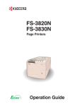
Front
Figure 1-1
1
Operator Panel
Used to specify printer functions and display the printer operating status.
2
Front Cover
When open, this cover gives you access to the internal component for replacing toner
containers. The cover must also be open to clear paper jam.
3
Top Paper Cassette (FS-C8008N)/Duplex Drawer (FS-C8008DN)
The cassette holds up to 500 sheets of A5 to A3 sizes. For the FS-C8008DN, the top
drawer includes the duplexer for two-sided printing.
4
Bottom Paper Cassette
The cassette holds up to 500 sheets of A5 to A3 sizes as a second paper source (for the
FS-C8008N).
5
MP (Multi-Purpose) Tray
The MP tray holds up to 150 sheets of standard and non-standard sizes with the
following weight:
• 150 sheets for 64 to 90 g/m²
• 30 sheets for 160 g/m² or more
Transparencies, envelopes, etc. must be fed using this tray.
1-5
1.2 Parts and Functions
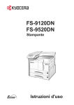
Figure 1-2
6
Paper Stopper
This stopper, when flipped up, prevents the printed sheet of large size from falling.
7
Face-down Tray
This tray receives printouts face down.
8
Power Switch
This switch turns printer power on and off.
Caution
In order to maintain operability and print quality, this printer operates a cooling fan for 30
minutes even after the power is turned off. For this reason, you should not unplug the
power cord even after turning off the power.
9
Left Cover
This cover is open by pulling the handle to clear paper jams.
10
Face-up Tray
This tray receives printouts face up.
1-6
1.2 Parts and Functions
1.2.2
Internal
Figure 1-3
1
Black Toner Container
This container holds black (K) toner. You must replace the container when the toner
run out.
2
Main Charger Unit
This is an electrical component used to transfer the toner onto the drum unit. The main
charger unit must be cleaned when you replace the toner container.
3
Yellow Toner Container
This container holds yellow (Y) toner. You must replace the container when the toner
run out.
4
Magenta Toner Container
This container holds magenta (M) toner. You must replace the container when the toner
run out.
5
Cyan Toner Container
This container holds cyan (C) toner. You must replace the container when the toner run
out.
6
Power Cord Connector
This connector accepts the power cord supplied with the printer.
Caution
In order to maintain operability and print quality, this printer operates a cooling fan for 30
minutes even after the power is turned off. For this reason, you should not unplug the
power cord even after turning off the power.
1-7
1.2 Parts and Functions
7
Waste Toner Box
This plastic box collects waste toner for later disposal. The box has a cap which is used
to seal the box opening when being disposed of.
8
Fuser Unit
The fuser unit fixes the toner permanently on the paper. The fuser becomes very hot
during printing.
9
Paper Transfer Unit
The paper transfer unit transports paper from the paper source for developing and
fixing images.
10
Primary Transfer Unit
This unit is used to create the image developed by toner and to transfer it onto the
surface of the paper.
1-8
1.2 Parts and Functions
1.2.3
Rear
Figure 1-4
1
Vents
Air is purged through these vents to cool down the inside.
2
USB Interface Connector
This connector is a USB interface that conforms to the Full-Speed USB 2.0. Use a USB
cable between this connector and the USB port on a computer.
3
Memory Card Slot
This slot receives a memory card. A memory card can hold fonts, macros, forms, etc.,
that can be downloaded in the printer’s memory. For details, see Appendix A Options,
section A.3.1 Memory Card on page A-7.
4
Paper Feeder Right Cover
This cover is opened to clear paper jams in the paper feeder section.
5
Network indicators
These indicators light according to the communication status with the network.
10BASE-T indicator (10): Lights when you are connected to the network at 10 Mbps.
100BASE-TX indicator (100): Lights when you are connected to network at 100 Mbps.
Status indicator (ST): Flashes during data communication.
6
Network Interface Connector
Connects to the network via a 10BASE-T/100BASE-TX network cable.
7
Parallel Interface Connector
This connector is for a standard Centronics parallel interface cable from the computer.
Connect this connector to the computer’s parallel port.
8
Option Interface Card Slot (Network/Serial) [OPT]
This slot holds an optional network interface card for network printing or a serial
interface board kit. (An optional Hard disk can’t be used in this slot.) For details see
Appendix A Options.
1-9
1.2 Parts and Functions
9
Hard Disk Slot (HDD)
This slot holds an optional hard disk for storing print jobs. A Kyocera Mita manufactured
hard disk must be used. For details, see Appendix A Options, section A.3.8 Hard Disk on
page A-12.
10
Exhaust Duct
Air is purged through these vents to cool down the inside.
11
Quick Reference Guide Holder
Use this holder to store the included Quick Reference Guide for easy access.
1-10
Chapter 2
Handling Paper
The printer can use a variety of media in various sizes. However, any media you will choose
to use with the printer must be in accordance with the guidelines and specifications in this
chapter. Use of paper not satisfying these guidelines and specifications may cause problems
such as frequent paper jams, poor quality printing, and possible damage to the printer
mechanism.
Even meeting the instructions provided in this chapter, special media such as transparencies,
labels, envelopes, non-standard-size paper must be fed directly from the printer’s MP
(multi-purpose) tray and delivered in the face-up tray in ‘straight path’ manner. For details
on use of MP tray, see Chapter 3 Using the Operator Panel, section 3.10.1 MP Tray Mode
on page 3-69.
2.1 General
2.1
General
The Ecosys Color FS-C8008 Series printers are designed for high-grade bond (copy) paper,
like those widely used for ordinary xerographic copiers. The printers will also support other
types of paper as long as they meet the standards explained in this chapter.
Selecting the right paper is very important. Use of unsuitable paper can cause paper jams,
misfeed, curling, poor print quality, and even worse, printer damage. This chapter shows
you how to use your printer in a way that will ensure efficient, error-free printing and
minimal printer damage. This practice will increase your office productivity.
Kyocera Mita will not be liable for any problems that may occur if you use paper that
does not meet these standards.
Note
2.1.1
Available paper types
The FS-C8008 Series printers can use almost any type of printer paper. These printers
accept paper used for xerographic copiers as well.
Paper comes in three generic grades: economy, standard, and premium. The grades are
determined by how easily the paper can pass through the printer. This depends on the
smoothness, size, moisture content, and cutting of the paper. The higher the grade, the less
risk of problems (such as paper jams), and higher the print quality.
The differences in paper characteristics of different paper makers also affect the printer
performance. High-performance printers can produce high-quality results only when the
right types of paper are selected. Low-priced paper is not always economical, especially if it
ends up causing frequent printing problems.
Paper of the different grades is available in basis weights (explained later). The recommended
basis weights of paper for the printers are 16, 20, and 24 pounds. When expressed in grams
per square meter, the recommended basis weights range from 60 to 90 g/m².
2.1.2
Paper specifications
Table 2-1 summarizes the basic paper specifications. Details are given on the subsequent
pages.
Item
Values
Weight (basis weight)
Cassette: 64 to 90 g/m² (17 to 24 lb/ream)
MP tray: 64 to 220 g/m² (17 to 58 lb/ream)†
Thickness
0.086 to 0.110 mm (3.4 to 4.3 mils)
Dimensions
See Table 2-3.
Dimensional accuracy
±0.7 mm (±0.0276 inches)
Squareness of corners
90 ±0.2 °
Moisture content
4 to 6 %
Table 2-1
2-2
2.1 General
Item
Values
Direction of grain
Long grain
Pulp content
80 % or more
Table 2-1 (Continued)
†
2.1.3
Paper of 135 to 220 g/m² thick should be A4 or Letter size and fed laterally.
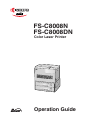
Minimum and Maximum Paper Sizes
148 mm
5-13/16 inches
The minimum and maximum paper sizes are as follows. For non standard paper such as
cut-sheet, the MP (multi-purpose) tray must be used.
Minimum
Paper
Size
458 mm
18 inches
80 mm
3-1/8 inches
Maximum
Paper Size
310 mm
12-3/16 inches
Figure 2-1
2.1.4
Recommended Paper
The following products are recommended for use with the printer for optimum performance.
Size
Product
Weight
Letter, Legal
Hammermill LASER PRINT
90 g/m² (24 lb)
A4, A3
NEUSIEDLER COLOR COPY
90 g/m²
Table 2-2
2-3
2.2 Selecting the Right Paper
2.2
Selecting the Right Paper
To get clean, crisp printouts from laser printers all the time, select high-quality printer paper
that meets the printer’s requirements. Laser printers use laser beams, electrostatic discharge,
toner, and heat, all of which affect the paper. Furthermore, paper slide, bends, and twists as
it passes through laser printers during printing. Therefore, printer paper must be able to
withstand such great stress.
This section describes the major considerations for selecting the right printing paper.
2.2.1
Guidelines
Paper conditions
Do not use paper with folded edges, curls, warps, smudges, tears, or embossing. Also do
not use paper containing lint, clay, or paper debris. Using such paper may cause illegible
printing, misfeeds, paper jams, etc., and shorten the product life of the printer. Never use
paper with surface coating or other surface treatment. The paper surface should be as
smooth and even as possible.
Paper composition
Do not use paper with surface-coating or containing plastic or carbon. The heat of fusing
causes such paper to emit toxic fumes.
Bond paper should have at least an 80 % pulp content. The percentage of cotton and other
fibers should not exceed 20 %.
Paper sizes
Table 2-3 lists the standard paper sizes and dimensions. Note that certain paper sizes are
available only for MP tray feeding (as remarked) and face-up tray delivering. For details on
using MP tray, seeChapter 3 Using the Operator Panel, section 3.10.1 MP Tray Mode on
page 3-69.
The dimensional tolerances for these paper sizes are ±0.7 mm (±0.0276 inches) for both
length and width of paper. The corner angles must be 90 ±0.2 °.
MP tray
Size
Cassette or MP tray
Size
Monarch
3-7/8 × 7-1/2 inches
Ledger
11 × 17 inches
Business
4-1/8 × 9-1/2 inches
Legal
8-1/2 × 14 inches
Commercial #9
3-7/8 × 8-7/8 inches
Letter
8-1/2 × 11 inches
Commercial #6-3/4
3-5/8 × 6-1/2 inches
Executive
7-1/4× 10-1/2 inches
ISO DL
110 × 220 mm
Folio
210 × 330 mm
ISO C5
162 × 229 mm
ISO A3
297 × 420 mm
ISO A6
105 × 148 mm
ISO A4
210 × 297 mm
JIS B6
128 × 182 mm
ISO A5
148 × 210 mm
ISO B5
176 × 250 mm
JIS B5
182 × 257 mm
A3 Wide
310 × 432 mm
JIS B4
257 × 364 mm
Table 2-3
2-4
2.2 Selecting the Right Paper
MP tray
Size
Cassette or MP tray
Size
Ledger Wide
310 × 440 mm
ISO C4
229 × 324 mm
Statement
5-1/2 × 8-1/2 inches
Oficio II
8-1/2 × 13 inches
Hagaki
100 × 148 mm
8K
273 × 394 mm
Oufuku Hagaki
148 × 200 mm
16K
197 × 273 mm
Youkei 2
114 × 162 mm
Youkei 4
105 × 235 mm
Custom
80 × 148 mm to
310 × 458 mm
Table 2-3 (Continued)
2.2.2
Paper properties
Smoothness
Paper should have a smooth, uncoated surface. Paper with a rough or sandy surface can
cause gaps in printouts. However, paper with surfaces that are too smooth may cause
multiple-sheet feeding and fogging problems (fogging is a gray background effect).
Basis weights
Basis weight is the weight in pounds of 500 sheets (called a ream) of paper cut to the basic
size, which is 17 × 22 inches. The number of sheets in a ream and the basic paper size
relating to basis weights depend on paper classifications. In the metric system, the basis
weight is expressed in grams per square meter (g/m²).
Paper that is too heavy or too light may cause misfeeds, jams, and premature wear of printer
parts. Uneven weight of paper can cause multiple-sheet feeding, print defects, poor toner
fusing, blurring, and other print quality problems. The recommended basis weights for this
printer are between 64 and 90 g/m² (17 to 24 lb per ream).
When you use paper with basis weights of 135 to 220 g/m², use the face-up tray for
high-quality printouts.
Paper Weight Equivalence Table
The paper weight is listed with expression in U.S. bond weight (lb) and European metric
(g/m²). The shaded point indicates the standard weight.
U. S. Bond Weight (lb)
Europe Metric Weight (g/m²)
16
60
17
64
20
75
21
80
22
81
24
90
27
100
Table 2-4
2-5
2.2 Selecting the Right Paper
U. S. Bond Weight (lb)
Europe Metric Weight (g/m²)
28
105
32
120
34
128
36
135
39
148
42
157
43
163
47
176
53
199
Table 2-4 (Continued)
Thickness (Caliper)
Thick paper is called high-caliper paper and thin paper is called low-caliper paper. Paper
used by the printer should be neither too thick nor too thin. If you encounter paper jam,
multiple-sheet feed, or too light printing problems, the paper may be too thin. If you
encounter paper jam or too heavy printing problems, the paper may be too thick. The
recommended thickness of a sheet for this printer is between 0.086 and 0.110 mm (from 3.4
to 4.3 mils).
Moisture content
Moisture content is the percentage of the weight of water in paper. Moisture affects the
appearance, feeding, curling, electrostatic properties, toner fusing of the paper.
The moisture content of paper varies with the relative humidity in the room. If the room is
too humid, paper will absorb more moisture. The edges will swell and the paper will
become wavy. If the room is too dry and the paper loses moisture, the edges shrink and
tighten, and the print contrast may be degraded.
Wavy or tight edges can cause paper misfeeds and misalignments. The recommended
moisture content is between 4 and 6 %.
To maintain the correct moisture content level, store the paper in an environment that allows
moisture control. These are tips for moisture control:
•
•
•
•
•
Store paper in a cool, dry place.
Leave packages of paper wrapped as long as possible. Rewrap unused paper.
Return paper to its paper carton, whenever possible. Place the cartons on a pallet or
other furniture so that they are not in direct contact with the floor.
Before using paper stored for an extended period of time, condition it in the printer’s
environment for at least 48 hours.
Do not expose paper to heat, direct sunlight, or damp.
Grain
Technically, grain is the direction of paper in the paper machine. Grain is parallel with the
direction of movement in the paper machine. Grain long means that the grain runs along the
length of the sheet, and grain short means that the grain runs along the width of the sheet.
Because grain short causes paper feed problems, always select grain long for the printers.
2-6
2.2 Selecting the Right Paper
2.2.3
Other properties of paper
Porosity
The density of paper structure, which indicates the compactness of the fiber bonding. It is
also the characteristic that allows air to pass through paper (i.e., air permeability).
Stiffness
The ability of paper to resist deformation under stress. In the printer, limp paper can buckle
and too stiff paper can bind. Both conditions result in paper jams.
Curl
Most paper naturally tends to curl one way. To produce flat printouts, load the paper sheets
so that the upward pressure from the printer can correct their curling. When loading paper, it
is also important to distinguish between the front side and backside of the paper. Be sure to
follow the paper loading instructions printed on the paper carton.
Electrostatic discharge
During the printing process, paper is given an electrostatic charge to attract the toner.
Therefore, the paper must discharge the static electricity so that the printouts do not stick to
each other in the output tray.
Whiteness
The contrast of printed images depends on the whiteness of the paper. Whiter paper
produces sharper and clearer images.
Quality control
Uneven paper sizes, corners that are not square, jagged paper edges, irregularly cut sheets,
torn edges and corners, etc. can cause various printer troubles. Before purchasing paper, find
out whether the paper store always takes measures to prevent such problems in its products.
Packaging
Paper sheets should be shipped in strong cartons to protect them from damage during
transportation. Before purchasing paper, make sure the store ships its products in proper
packages.
2-7
2.3 Loading Paper
2.3
Loading Paper
The following explains the procedure for loading paper in the cassette and the MP tray.
Fan the media (paper/transparencies), then tap it on a level surface to avoid media
jams or skewed printing.
Caution
Figure 2-2
2.3.1
Loading Paper into the Cassette
Perform the following procedure to load paper into the cassette.
1
2
Pull out the paper feed cassette until it stops.
Lift the paper feed roller located on the right side of the cassette upright.
Paper Feed
Roller
Figure 2-3
2-8
2.3 Loading Paper
3
Adjust the position of the paper guides according to the size of the paper you will
use. To move the paper guides, press the green-colored knobs.
Paper Stopper
Paper Guide
Figure 2-4
4
Align the paper stopper correctly with the markings in the cassette that match the
paper size:
Figure 2-5
5
Square the edges of the paper and insert into the paper feed cassette. Be sure that the
paper does not exceed the paper limit indicators. The paper feed cassette can hold up
to about 500 sheets. Printing is performed on the underside of the paper.
Paper Limit
Indicator
Figure 2-6
6
Lower the paper feed roller to its original position. Close the paper feed cassette.
2-9
2.3 Loading Paper
2.3.2
Loading Paper into the MP (Multi-Purpose) Tray
Perform the following procedure to load paper into the MP tray.
1
Open the MP tray located on the right side of the printer.
MP Tray
Figure 2-7
2
Adjust the position of the paper guides according to the size of the paper you will
use.
Paper Guide
Paper Guide
Figure 2-8
3
Square the edges of the paper and insert into the MP tray.
Figure 2-9
4
Set the MP tray paper size on the printer’s operator panel. Refer to Chapter 3 Using
the Operator Panel, section 3.10.2 Setting MP Tray Paper Size on page 3-70.
2-10
2.4 Special Paper
2.4
Special Paper
Besides plain paper, this printer can use the following types of special paper:
Paper type to be used
Media type to be selected
Thin paper (60 to 64 g/m²)
Vellum
Thick paper (90 to 200 g/m²)
Thick
Colored paper
Color
Recycled paper
Recycle
Overhead projector transparencies Transparency
Postcards
Cardstock
Envelopes
Envelope
Label
Labels
Table 2-5
You can assign one of these special paper type to a paper cassette or MP (multi-purpose)
tray by using the printer’s operator panel keys. Then, the printer can automatically select the
paper cassette or multi-purpose tray to feed the special paper from and internally adjust the
electrical parameters for optimum printing performance according to the special paper type.
For details, see Chapter 3 Using the Operator Panel, section 3.10.4 Setting the Cassette
Paper Type on page 3-73.
Note that some types of special paper do not allow feeding from the paper feeder cassette or
duplex (two-sided) printing.
2.4.1
Selecting the Special Paper
Since special paper differs significantly in paper composition and quality, special paper is
more likely to cause problems than white bond paper during printing. When using special
paper, be sure that they are manufactured for photocopiers and/or laser printers.
Before purchasing any special paper, make a test print using the printer and check whether
the results are satisfactory.
Kyocera Mita shall not be liable for any danger to a person or machine that is caused
by using special paper (e.g., fumes emitted from the special paper).
Note
To avoid problems, stack transparencies, labels, or envelopes on the tray or cassette face up.
Major considerations for each type of special paper are given below.
2-11
2.4 Special Paper
Transparency
Transparencies for overhead projectors must withstand the heat of fusing during the printing
process. The recommended transparency product is as follows:
3M CG3700 (Letter, A4)
Transparencies must be placed on the MP (multi-purpose) tray with the long edge towards
the printer. To avoid problems, stack transparencies face up on the face-up tray.
MP Tray
Figure 2-10
When unloading transparencies (e.g., for clearing jams), hold them carefully by the edges to
avoid leaving fingerprints on them.
Adhesive-backed labels
Label paper must be fed manually.
For printing on labels, use extreme care so that the adhesive may not come in direct contact
with any part of the printer. Adhesives that stick to the drum or rollers will cause printer
damage.
Labels consist of three parts. Printing is done onto the top sheet (also called the face sheet).
The adhesive contains chemicals. The carrier sheet (also called the backing paper or liner)
bears the top sheet. This composition of labels can cause more problems than other print
forms during printing.
Top sheet (white bond paper)
Adhesive
Carrier sheet
Figure 2-11
When using label paper, do not leave gaps between the arranged labels (i.e., top sheets).
Labels arranged with gaps in-between can easily be peeled off during printing, causing
serious jam problems.
2-12
2.4 Special Paper
When the label paper has extra margin around the label’s outside edges that correspond to
the margins of the printable area, do not remove the extra top sheet from the carrier sheet
until printing is finished.
Allowed
Not allowed
Top sheet
Carrier sheet
Figure 2-12
When selecting labels, make sure to use only those meeting the following requirements:
Item
Value
Top sheet weight
44 to 74 g/m² (12 to 20 lb)
Total weight
104 to 151 g/m² (28 to 40 lb)
Top sheet thickness
0.086 to 0.107 mm (3.9 to 4.2 mils)
Total thickness
0.115 to 0.145 mm (4.5 to 5.7 mils)
Moisture content
4 to 6 % (composite)
Table 2-6
Postcards
Fan the stack of postcards and align the edges before loading them in the MP tray. Make
sure the postcards you are going to set are not curled. Feeding curled postcards may cause
paper jams.
Some postcards have rough edges on the back (those are created when the paper is cut). In
this case, put the postcards on a flat place and rub the edges with, for example, a ruler to
smooth them.
Figure 2-13
2-13
2.4 Special Paper
Envelopes
Envelopes must be fed manually.
Since the composition of an envelope is more complex than that of ordinary paper, it is not
always possible to ensure consistent printing quality over the entire envelope surface.
Normally, envelopes have a diagonal grain direction. See section Grain on page 2-6. This
direction can easily cause wrinkles and creases when envelopes pass through the printer.
Before purchasing envelopes, make a test print to check whether the printer accepts the
envelope.
Other handling cautions follow:
•
•
•
Do not use envelopes that have an encapsulated liquid adhesive.
Avoid a long printing session for envelopes only. Extended envelope printing can cause
premature printer wear.
To avoid jams caused by curled envelopes, stack the printed envelopes no higher than
10 on the output tray.
Colored paper
Colored paper should have the same specifications as the white bond paper listed. In
addition, the pigments in the paper must be able to withstand the heat of fusing during the
printing process (up to 200 °C or 392 °F).
Pre-printed paper
Pre-printed paper should basically be bond paper. The inks on the paper must be able to
withstand the heat of fusing during the printing process and must not be adversely affected
by silicon oil. Do not use paper with any kind of coating, such as calendar stock.
Recycled paper
Select recycled paper that has the same specifications as white bond paper. See Table 2-1 on
page 2-2. Recycled paper, however, does not have to be as white as white bond paper.
Before purchasing recycled paper, make a test using the printer and check whether
the print quality is satisfactory.
Note
2-14
Chapter 3
Using the Operator Panel
This chapter provides the information you need to configure the Ecosys Color printer. In
general you need to use the operator panel only to make default settings. You can make most
changes to the printer settings using the printer driver trough the application software.
Changes to printer settings made using a software application override changes made
using the operator panel.
Note
You can also rely on other printer utilities such as Kyocera Mita PrintMonitor if you need to
change settings that are not available on the printer driver. It will allow you remotely access
to printer settings. Printer utilities are supplied in the CD-ROM supplied with the printer.
The chapter describes the operator panel in detail, including its menus and the procedures
for changing various printer settings.
3.1 Understanding the Operator Panel
3.1
Understanding the Operator Panel
The operator panel on the top of the printer has a 2-line by 16-character liquid crystal
display (LCD), eight keys, and three indicators (LED).
Figure 3-1
Messages that appear on the display and functions of indicators and keys are explained in
the sections that follow.
3.1.1
Message Display
The message display on the operator panel shows:
•
•
Status information, the eight messages listed below which are displayed during normal
operation.
Error codes, when the printer requires the operator’s attention; as explained in
Chapter 4 Troubleshooting.
Status Information
Message
Meaning
Self test
The printer is performing self-diagnostics after power-up.
Please wait
The printer is warming up and is not ready.
When the printer is switched on for the first time, this message
will take several minutes.
The color calibration function is being performed automatically
as you powered on the printer.
Please wait
(Calibrating)
You can also execute this function manually on the operator
panel. For details, see Section 3.13.12 Color Calibration on page
3-100.
Ready
The printer is ready to print.
Processing
The printer is receiving data to print. This is also shown when the
printer is reading a memory card or hard disk.
Table 3-1
3-2
3.1 Understanding the Operator Panel
Message
Meaning
Sleeping
The printer is in sleep mode. The printer wakes from sleep mode
whenever a key on the operator panel is pressed, the cover is
opened or closed, or a print job is received. The printer then
warms up and goes on-line. For details on sleep mode, see Sleep
Timer Timeout Time on page 3-91.
Cancelling data
Jobs inside the printer are being canceled. To cancel a job, see
Section 3.1.3 Keys on page 3-6.
Waiting
The printer is waiting for the rest of print job before completing
the last page. Pressing the GO key allows you to obtain the last
page immediately. See below.
FormFeed TimeOut
The printer is printing the last page after a waiting period.
Table 3-1 (Continued)
Error codes
See Chapter 4 Troubleshooting.
3.1.2
Indicators in Message Display
Figure 3-2
Interface Indicator (INTERFACE)
The interface indicator shows the interface that is currently in use:
PAR
USB
SER
NET
OPT
---
Parallel interface is in use.
USB interface is in use.
Serial (RS-232C) interface is in use. (option)
Network interface is in use.
Network interface is in use. (option)
No interface is in use.
Each interface has a timeout time of 30 seconds during which the other interface should wait
to receive a print job. Even a print job has been complete on the interface, you should wait
for this period until the other interface begins printing the job.
3-3
3.1 Understanding the Operator Panel
Paper Size Indicator (SIZE)
This indicator indicates:
•
•
While the printer is in standby, the paper size of the cassette. The default paper cassette
is determined by the operator panel keys. For details, see Section 3.10 Paper Handling
on page 3-69.
While the printer is printing, the paper size used to format the document to print by the
application software.
The abbreviations used to indicate the paper sizes and their dimensions are as follows:
A3
A4
A5
A6
B4
B5
B6
LT
LD
LG
MO
ISO A3 (29.7 × 42 cm)
ISO A4 (21 × 29.7 cm)
ISO A5 (14.8 × 21 cm)
ISO A6 (10.5 × 14.8 cm)†
JIS B4 (25.7 × 36.4 cm)
JIS B5 (18.2 × 25.6 cm)
JIS B6 (12.8 × 18.2 cm)†
Letter (8-1/2 × 11 inches)
Ledger (11 × 17 inches)
Legal (8-1/2 × 14 inches)
Monarch (3-7/8 × 7-1/2 inches)†
BU
Business (4-1/8 inches)†
DL
ISO DL (11 × 22 cm)†
C4
ISO C4 (22.9 × 32.4 cm)†
C5
ISO C5 (16.2 × 22.9 cm)†
b5
ISO B5 (17.6 × 25 cm)†
EX
Executive (7-1/4 × 10-1/2 inches)†
#6
Commercial 6-3/4 (3-5/8 × 6-1/2 inches)†
#9
Commercial 9 (3-7/8 × 8-7/8 inches)†
HA
Japanese Postcard (10 × 14.8 cm)†
OH
Return Postcard (20 × 14.8 cm)†
O2
Oficio II (8-1/2 × 13 inches)†
a3
A3 Wide (31× 43.2 cm)†
ld
Ledger Wide (31× 44 cm)†
8K
8 kai (27.3 × 39.4 cm)†
16K
16 kai (19.7 × 27.3 cm)†
ST
Statement (5-1/2 × 8-1/2 inches)†
FO
Folio (21 × 33 cm)†
Y2
Yokei 2 (11.4 × 16.2 cm)†
Y4
Yokei 4 (10.5 × 23.5 cm)†
CU
Custom Size (8 × 14.8 cm to 31 × 45.8 cm)†
†
Only with MP tray feeding
3-4
3.1 Understanding the Operator Panel
Paper Type Indicator (TYPE)
This indicator shows the paper type defined for the current paper casette. The paper type can
be manually defined using the operator panel. For more information, see Section 3.10 Paper
Handling on page 3-69.
The following abbreviations are used:
(none)
PLAIN
TRNSPRNCY
PREPRINTE
LABELS
BOND
RECYCLED
VELLUM
ROUGH
LETTERHEA
COLOR
PREPUNCH
ENVELOPE
CARDSTOCK
COATED
THICK
CUSTOM1 (to 8)
†
Auto
Plain paper
Transparency†
Pre-printed paper
Labels†
Bond paper
Recycled paper
Vellum†
Rough paper
Letterhead
Colored paper
Pre-punched paper
Envelope†
Card stock†
Coated paper
Thick paper
Custom 1 (to 8)
Only with MP tray feeding
READY, DATA, and ATTENTION Indicators
The following indicators light during normal operation and whenever the printer needs
operator’s attention. Depending on the status of lighting, each indicator has the following
meaning:
Indicator
READY
Description
Flashing. Indicates an error that you can recover by yourself, such as
the loose front cover. For details, see Chapter 4 Troubleshooting, section 4.3 Error Messages on page 4-6.
On. Indicates that the printer is ready and on-line. The printer prints the
data it receives.
Off. Indicates that the printer is off-line. Data can be received but will
not be printed until the printer is on-line by pressing the GO key. Also,
indicates when printing is automatically stopped due to the occurrence
of an error. For details see Chapter 4 Troubleshooting, section 4.3 Error
Messages on page 4-6.
DATA
Flashing. Indicates that a data is being received from the computer.
On. Indicates either that data received is being processed before printing starts, or that data received is being written to a memory card or a
hard disk.
ATTENTION
Flashing. Indicates that the printer requires maintenance or is warming up.
On. Indicates the occurrence of a problem or an error. For details, see
Chapter 4 Troubleshooting, section 4.3 Error Messages on page 4-6.
Table 3-2
3-5
3.1 Understanding the Operator Panel
3.1.3
Keys
The operator panel keys are used to configure the printer operation. Note that certain keys
have the secondary function.
Note
The printer has a parallel, serial, and an optional network interface. Configuration to
the printer settings made with these keys affect only one of these interfaces that is
currently active (indicated by the INTERFACE indicator on the message display). See
Interface Indicator (INTERFACE) on page 3-3.
GO Key
The GO key switches the printer between on-line and off-line. Use this key to:
•
•
•
Toggle the printer’s on-line and off-line states. You can temporarily stop the print job by switching
the printer off-line.
Print and feed out one page when the printer displays Waiting.
Recover from certain errors
CANCEL Key
This key is used to:
•
•
•
Cancel a printing job
Stop the alarm sound
Reset numeric values or cancels a setting procedure while using menu system
To cancel a printing job:
1
While the printer displays Processing, press the CANCEL key.
Print Cancel? appears on the message display followed by the interface which
the job to cancel is on. The interface is indicated by one of the following message:
Parallel
USB
Network
Serial (option serial interface)
Option (option network interface)
2
Press the ENTER key. Cancelling data appears on the message display and
printing stops after the current page is printed.
3-6
3.1 Understanding the Operator Panel
MENU Key
The MENU key lets you enter the menu system to change the setup and printing
environment of the printer.
Pressing this key during a menu selection will terminate the selection and return the printer
to the normal operation.
Arrow Keys
The four arrow keys are used in the menu system to access a desired item or enter numeric
values.
The arrow key with the question mark (?) may be pressed when the paper jam message has
appeared on the message display. Then a help message will appear to facilitate jam clearing
in the location.
ENTER Key
This key is used to:
•
•
Note
Finalize settings of numeric values and other selections.
Set the paper source when Use alternative? is shown in the message display.
If you hold down the ENTER key and press the MENU key when Ready is shown on
this printer, the AdministrationID menu will be displayed. This menu is the setting
menu for administration under the Account Management System and is normally not
used. Press the MENU key to return to the Ready display.
3-7
3.2 Using the Menu Selection System
3.2
Using the Menu Selection System
3.2.1
Menu Selection System
This section explains how to use the menu selection system. The MENU key on the operator
panel allows you to use the menu to set or change the printer environment such as the
number of copies to print, emulation, etc., to your specific needs. Settings can be made
when Ready is indicated on the printer message display.
The printer obeys the most recently received printer settings sent from the application
software, or from the printer driver, which take priority over operator panel settings.
Entering the Mode Selection Menu
Press the MENU key when Ready is indicated on the printer message display.
The mode selection menu is displayed.
3-8
3.2 Using the Menu Selection System
Selecting a Menu
The mode selection menu is hierarchical. Press the U or V key to display the desired menu.
•
If the selected menu has a sub-menu, > is displayed after the menu.
Paper Handling >
Indicates that there is a sub-menu
Press the Z key to move to the sub-menu or Y key to go back.
•
> is displayed before the sub-menu.
Indicates that this is the sub-menu
>Type Adjust
>
Indicates that there is another sub-menu
Press the Z key to move to another sub-menu or Y key to go back.
•
>> is displayed before the second sub-menu.
Indicates that this is the second sub-menu
>>Paper Weight
Normal
Setting a Menu
Select the desired menu and press the ENTER key to set or change the configuration.
Press the U or V key to display the desired item and the ENTER key to finalize the value
or selections set.
Cancelling Menu Selection
If you press the MENU key when selecting a menu, the message display returns to Ready.
Settings that are received from application software and the printer driver will take
priority over settings made in the operator panel.
Note
3-9
3.2 Using the Menu Selection System
3.2.2
Menu System Road Map
The following is the hierarchy diagram of the menu selection system of the printer.
For details about menu selection operations, see page 3-8.
Ready
PAR A4 PLAIN
MENU Key
Print
Menu Map
Print
Status Page
e-MPS
>
>Quick Copy
>Private/Stored
>Print VMB Data
>List of VMB
>List of
Code JOB
>e-MPS
>
Configuration
>>Quick Copy
32
>>Temp. Code JOB
Size
1550MB
>>Perm. Code JOB
Size
1550MB
>>VMB Size
1550MB
Continued on the next page
3-10
3.2 Using the Menu Selection System
Continued
Interface
>
Parallel
Interface
USB
Interface
>
Network
Interface
>
Serial
Interface
>
Option
>Parallel I/F
Nibble (high)
>NetWare
Off
>NetWare
On
>
>>NetWare Frame
Auto
>TCP/IP
Off
>TCP/IP
On
>
>>DHCP
Off
>>DHCP
On
>EtherTalk
Off
>EtherTalk
On
>>IP Address
000.000.000.000
>Network Status
Page
Off
>Network
Status
Page
On
>>Subnet Mask
000.000.000.000
>>Gateway
000.000.000.000
>Baud Rate
9600
>Data Bits
8
>Stop Bits
1
>Parity
None
>Protocol
DTR (pos.)&XON
>NetWare
Off
>NetWare
On
>
>>NetWare Frame
Auto
>TCP/IP
Off
>TCP/IP
On
>
>>DHCP
Off
>>DHCP
On
>EtherTalk
Off
>EtherTalk
On
>Opt. StatusPage
On
>Opt.
StatusPage
Off
>>IP Address
000.000.000.000
>>Subnet Mask
000.000.000.000
>>Gateway
000.000.000.000
Emulation
PCL 6
Emulation
>
KC-GL
Emulation
>
KPDL
Emulation
>
KPDL (AUTO)
>KC-GL Pen
>
Adjust
Pen (1)
>KC-GL Page Set
[SPSZ]
>Print KPDL errs
Off
>Print KPDL errs
On
>Alt. Emulation
PCL 6
>Print KPDL errs
Off
>Print
KPDL errs
On
Continued on the next page
3-11
>>Pen(1) Width
01 dot(s)
>>Pen(1) Color
Black
3.2 Using the Menu Selection System
Continued
Font
>
>Font Select
Internal
>Font Select
Option
>
>Code Set
IBM PC-8
>> I000
>
>>Courier
Regular
>>Courier
Dark
>List of
Internal Fonts
>>Letter Gothic
Regular Gothic
>>Letter
Dark
>List of
Option Fonts
>>Size
012.00 point(s)
>>Pitch
10.00 cpi
Page Set
>
>Copies
001
>Orientation
Portrait
>Orientation
Landscape
>Page Protect
Auto
>Page Protect
On
>LF Action
LF only
>CR Action
CR only
Print Quality
>
>Tone
Normal
>Tone
Fine
>Gloss Mode
Low
>Gloss
Mode
High
Opt. ROM
>
Hard Disk
>
RAM Disk Mode
Off
RAM Disk Mode
On
>Read Data
>List of
Partitions
>Read Data
>Write Data
>Delete Data
>Format
>List of
Partition
>
>RAM Disk Size
>Read Data
>Write Data
>Delete Data
>List of
Partition
Continued on the next page
3-12
3.2 Using the Menu Selection System
Continued
Memory Card
>
>Read Fonts
>Write Data
>Write Data
>Delete Data
>Format
>List of
Partition
Paper Handling >
>MP Tray Mode
Cassette
>MP
Tray Mode
First
>MP Tray Size
A4
>MP Tray Type
Plain
>Cassette 1 Type
Plain
>Cassette 2 Type
Plain
>Feed Select
Cassette 1
>Duplex Mode
None
>Stack Select
Facd-down
tray
>Stack
Select
Facd-up tray
>Sorter Mode
Sorter
>Override A4/LT
Off
>Override
A4/LT
On
>Type Adjust
Custom 1
>Reset Type
Adjust
>
>>Paper Weight
Normal
>>Fuser Mode
Low
>>Fuser
Mode
Middle
>>Duplex Path
Enable Path
>>Duplex
Disable
Color Mode
Color Mode
Color
Monochrome
Continued on the next page
3-13
3.2 Using the Menu Selection System
Continued
Life Counters
>
>Total Print
>New Toner [C]
Installed
>New Toner [M]
Installed
>New Toner [Y]
Installed
>New Toner [K]
Installed
Others
>
>MSG Language
English
>Form Feed
Time Out 000sec.
>Sleep Timer
>
030 min.
>>Sleep Mode
On
>>Sleep
Mode
Off
>Print HEX-DUMP
>Printer Reset
>Resource Prot.
Off
>Buzzer
Off
>Buzzer
On
>Auto Continue
Mode
Off
>Auto Continue >
Mode
On
>>Auto Continue
Timer
030sec.
>Finishing
Error
>
>>Duplex
On
>>Duplex
On
>Service
>
>>Print Status
Page
>>Color
Calibration
>>Print Test
Page 1
>>Print Test
Page 2
>>Dehumidifier
Off
>>Dehumidifier
On
>>Maintenance
[A]
>>Maintenance
[B]
>>Maintenance
[C]
>>Drum
3-14
3.3 Menu Map and Status Pages
3.3
Menu Map and Status Pages
This section explains the procedure for printing the printer’s internal information using the
menu selection system. The menu map is usefull as a reference to guide yourself through the
menu selection system.
The status page is a list of parameters and settings for most basic printer configurations. You
may be required to produce a status page when requesting service to the printer.
3.3.1
Printing a Menu Map
The printer prints a full list of menu selection system — Menu Map. Note that menus shown
in the list may vary depending on which optional units installed in the printer.
1
2
Press the MENU key.
Press the U or V key repeatedly until Print Menu Map appears.
Print
Menu Map
3
Press the ENTER key. A question mark (?) appears.
Print
Menu Map ?
4
Press the ENTER key. The message Processing appears and the printer prints a
Menu Map.
3-15
3.3 Menu Map and Status Pages
FS-C8008N Page Printer
MENU MAP
Figure 3-3
3-16
3.3 Menu Map and Status Pages
3.3.2
Printing a Status Page
You can check the printer’s current status, including available memory space and option
settings by printing a status page.
1
2
Press the MENU key.
Press the U or V key repeatedly until Print Status Page appears.
Print
Status Page
3
Press the ENTER key. A question mark (?) appears.
Print
Status Page ?
4
Press the ENTER key again. The message Processing appears and the printer
prints a status page.
For a sample status page and its full description, see Understanding the Status Page
on page 3-18.
3-17
3.3 Menu Map and Status Pages
Understanding the Status Page
The numbers in the following diagram refer the items explained below the diagram. The
items and values on the status page may vary depending on the printer’s firmware version.
FS-C8008N Page Printer
STATUS PAGE
Firmware Version:
Hardware Information
Released:
1
Memory
2
3
4
Page Information
Installed Options
Network Status
Emulation
5
6
Error Log
7
8
Consumable Status
9
Interfaces
10
Figure 3-4
1
Software Version
This item shows the version and release date of the printer firmware.
2
Hardware Information
This item shows various printer settings for hardware-related items:
•
•
•
•
•
•
•
MP tray paper size and type
Paper cassette size and type
Draft mode
Buzzer control
Host buffer size
Sleep time timeout time
Formfeed timeout time
3-18
3.3 Menu Map and Status Pages
3
Memory
This item shows:
•
•
•
•
4
Standard memory in the printer (128 MB)
Option memory slot status (Slots 1 and 2) in megabytes
Total memory in the printer
Current status of the RAM disk
Page Information
This item shows the page related items:
•
•
•
5
Tone mode, Normal or Fine
Number of copies, from 1 to 999
Total page count
Installed Options
This item shows the options installed in the printer:
•
•
•
6
Hard disk
Option ROM
Memory card
Network Status
This item shows the IP address, subnet mask address, and default gateway address for
the network interface card in the printer.
7
Emulation
This item shows all available emulations of the printer. The PCL 6 emulation is set as
default when the printer is shipped from the factory. The emulations are:
•
•
•
8
PCL 6
KPDL3
KC-GL
Error Log
This item shows the last three instances of the following types of errors, listing them in
the order of occurrence:
•
•
•
•
KPDL (PostScript) errors
Memory overflow
Print overrun
File-not-found
The most recent error is displayed on the topmost line of Error Log. Error information
is cleared when the printer is powered off.
The error log information is intended for service purpose.
9
Consumable Status
This item shows the approximate level of remaining toner. When the value is 100, the
toner container is full. The closer to 0, the smaller the amount of remaining toner.
10
Interface Information
This information shows the emulation and the default font for all interfaces installed in
the printer.
3-19
3.4 e-MPS
3.4
e-MPS
e-MPS is an abbreviation for ‘enhanced-Multiple Printing System’ which implements the
following functions that are available from the printer driver:
•
•
Job Retention
Job Storage
In either job mode, when printing a document, the print data is transferred from the
computer to the printer then stored on the printer’s hard disk. Since copies of the document
are printed using the stored data, printing is performed faster with less computer spooling
time and less network traffic.
•
To use the e-MPS system, an optional hard disk must be installed in the printer.
For details, see Appendix A Options.
•
The RAM disk may also be used in the Proof-and-Hold and Private Print modes.
See Using the RAM Disk on page 3-67 for details on RAM disk setup.
Note
Job Retention
Job Retention has four modes as summarized below. These modes are selected when you
choose on the printer driver through the application software:
Quick Copy
Proof-and-Hold Private Print
Stored Job
Primary function
To later print addi- To proof the first To hold the docutional copies
copy before print- ment in printer to
ing multiple copies prevent unauthorized access
To electronically
store documents
such as fax cover
pages
Start storing by
Printer driver
Printer driver
Printer driver
Printer driver
On terminating
print setting from
application software
Prints simultaneously
Prints one copy
simultaneously
Does not print
Does not print
Retrieved by
Operator panel
Operator panel
Operator panel
Operator panel
Default number of Same as storing
copies printed at
(can be changed)
retrieval
One less
Same as storing
One
(can be changed)
(can be changed)
Maximum number 32, expandable to
50
of jobs stored†
32, expandable to
50
Depends on the
Depends on the
hard disk capacity hard disk capacity
(Private jobs are
deleted automatically once it is
retrieved.)
PIN security
No
Yes
Yes (if necessary)
Data after printing Stored
Stored
Deleted
Stored
Data at power off
Deleted
Deleted
Stored
No
No
Yes
No
Deleted
Hard disk required Yes
Table 3-3
†
Jobs in excess will cause the earlier ones to be deleted.
3-20
3.4 e-MPS
Job Storage
Job storage stores print jobs either temporarily or permanently, or in virtual mailboxes, as
you click an appropriate radio button on the printer driver when printing from a computer.
Virtual Mailbox
Virtual mailbox is part of Job Storage, which stores print jobs on the hard disk without
printing. It enables you to retrieve jobs later from the operator panel or the KM-NET
Printer Disk Manager utility in the CD-ROM.
Each mailbox may be used by an individual who desires to share the printer in this mode.
By default, each mailbox is numbered from ‘Tray 001,’ ‘Tray 002,’ ... etc. To ‘post’ a job in
one of these mailboxes, you assign a numbered or named mailbox on the printer driver
when printing.
To retrieve the stored job for printing, see Retrieving Jobs from Virtual Mailbox (VMB) on
page 3-28.
The virtual mailbox can be used in PCL 6 emulation only.
Note
3.4.1
Using Quick Copy
This mode enables you to print the requested number of copies of a job, simultaneously
storing the job on the hard disk. When additional copies are required, you can reprint the
required number of copies from the printer operator panel. To print a job as a quick copy
job, see KX Printer Drivers Operation Guide.
The default number of print jobs that can be stored on the hard disk is 32. This value can be
increased to up to 50 from the e-MPS Configuration menu. For details, see Changing the
Maximum Number of Quick Copy/Proof-and-Hold Jobs on page 3-30. When the number of
jobs reaches the limit, the oldest job will be overwritten by the new one.
When the printer is turned off, all stored jobs will be deleted.
3-21
3.4 e-MPS
Printing Additional Copies using Quick Copy
To print additional copies of a job stored in the printer:
1
2
Press the MENU key.
Press the U or V key repeatedly until e-MPS > appears.
e-MPS
3
4
>
Press the Z key.
Press the U or V key repeatedly until >Quick Copy appears followed by the user
name (Harold, in this example). The user name is assigned at printing using the
printer driver.
>Quick Copy
Harold
5
Press the ENTER key. A blinking question mark (?) appears before the user name.
>Quick Copy
?Harold
6
Press the U or V key to display the desired user name, Arlen, in this example.
>Quick Copy
?Arlen
7
Press the ENTER key. The job name entered in the printer driver (Report, in this
example) appear with a blinking question mark (?) before the letters.
>Arlen
?Report
8
9
Press the U or V key to scroll to the desired job title.
Press the ENTER key. The number of copies to be printed can be set. To increase the
copy count, press the U key; to decrease the copy count, press the V key.
>Report
Copies
10
001
Press the ENTER key to finalize the copy count. The printer prints the specified
number of copies for the job.
3-22
3.4 e-MPS
Deleting a Quick Copy Job
All quick copy jobs are automatically deleted when the printer is turned off. If you desire to
explicitly delete a stored quick copy job, proceed as follows:
1
Follow steps 1 through 8 in the above section to let the title of the job to be deleted
displayed.
2
When the title of the job to be deleted is displayed, e.g. Report, below, press the
ENTER key. The cursor below the copy count starts to blink.
>Report
Copies
3
001
Press the V key repeatedly until Delete appears below the title.
>Report
Delete
4
3.4.2
Press the ENTER key. The stored quick copy job is deleted.
Using Proof-and-Hold
When you print multiple copies, this mode first prints one copy so that you can proof it
before continuing to print the remaining copies. Since you can proof the printouts before
printing the remaining copies, wastage of paper can be reduced.
The printer prints one copy and, at the same time, saves the print job on the hard disk/RAM
disk. You can also change the number of copies when resuming printing from the operator
panel.
When the printer is turned off, all stored jobs will be deleted.
Printing Remaining Copies of a Proof and Hold Job
Printing a Proof-and-Hold job on the operator panel is similar to printing a quick copy job.
See Printing Additional Copies using Quick Copy on page Chapter 3-22.
3-23
3.4 e-MPS
3.4.3
Printing a Private Print/Job Retention
In private printing, you can specify that a job is not printed until you release the job from the
operator panel. At sending the job from the application software, you can specify a 4-digit
access code in the printer driver. The job is released for printing by entering the access code
on the operator panel. Thus, this function ensures confidentiality of the print job.
In the job retention mode, access codes are not mandatory, but can be set on the printer
driver if printing with the PIN security is required. Then, the access code must be entered on
the operator panel to print a stored job. Print data will be stored in the hard disk/RAM disk
after printing. See KX Printer Drivers Operation Guide for the driver settings.
Releasing a Private/Stored Job
1
2
Press the MENU key.
Press the U or V key repeatedly until e-MPS > appears.
e-MPS
3
4
>
Press the Z key.
Press the U or V key repeatedly until >Private/Stored appears. The name
entered in the printer driver (Harold, in this example) also appears.
>Private/Stored
Harold
5
Press the ENTER key. A blinking question mark (?) appears before the user name.
>Private/Stored
?Harold
6
Press the U or V key to display the desired user name (Arlen, in this example).
>Private/Stored
?Arlen
7
Press the ENTER key. The user name and the job name (Agenda, in this example)
entered in the printer driver appear with a blinking question mark (?).
>Arlen
?Agenda
8
Press the U or V key to display the desired job title.
3-24
3.4 e-MPS
9
Press the ENTER key. The ID input line appears. Enter the four-digit access code
entered in the printer driver and press the ENTER key.
>Agenda
ID
0000
To enter the ID, press the Y or Z key to move the cursor to the number to be
changed and then enter the correct number by pressing the U or V key.
10
You can set the number of copies to be printed. To increase the copy count, press the
U key; to decrease the copy count, press the V key.
>Agenda
Copies
11
001
Press the ENTER key to finalize the copy count. The printer prints the specified
number of copies for the job.
Deleting a Private/Stored Job
You can individually delete stored jobs by performing the following procedure. Jobs saved
using Private Print will be automatically deleted if you turn the power off after printing, but
jobs saved using Stored Job will not be deleted automatically.
1
2
Follow steps 1 through 8 in the above section.
When the title of the job to be printed is displayed (Agenda, in this example), press
the ENTER key. Enter the four-digit access code entered in the printer driver and
press the ENTER key.
>Agenda
Copies
3
001
Press the V key repeatedly until Delete appears for the number of copies.
>Agenda
Delete
4
Press the ENTER key. The private job is deleted from the hard disk.
3-25
3.4 e-MPS
Printing a Code Job
Install the KM-NET Job Manager software from the CD-ROM supplied with the printer. To
do this, from the CD-ROM Main Menu, select Printer Utilities > Install KM-NET Job
Manager.
1
Browse through Windows Start > Programs > KYOCERA MITA > KM-Net >
Job Manager.
2
3
Enter the password for the software. Job Manager will start.
Click the Add printer icon (below). Select the Local or Network port.
Note
If you use the local parallel port to connect to the printer, make sure
that the printer driver is set to print to a local port. To check this out,
click the Details tab of the printer Properties, and note the Print to the
following port setting.
Add printer
icon
4
Follow the wizard until the Select printer dialog box is reached. When the printer
is found in the Printer List, click (highlight) it, then Finish.
5
Double click Model Name on the list. The jobs currently stored in the printer are
shown. To print the job, right click Job name and then click Print on the drop
down list that appears.
It is possible to select more than one job at a time by left clicking a job one by one
while pressing the Ctrl key on the computer keyboard.
The job remains intact even after printing. To permanently delete the job in the hard disk,
right click the job name on Job Manager, then click Delete on the drop down list that
appears.
3-26
3.4 e-MPS
Printing a List of Code Jobs
If you select Permanent Job Storage on the printer driver, you can have a List of Code Job
printed using the operator panel.
1
2
Press the MENU key.
Press the U or V key repeatedly until e-MPS > appears.
e-MPS
3
4
>
Press the Z key.
Press the U or V key repeatedly until >List of Code JOB appears.
>List of
Code JOB
5
Press the ENTER key. A question mark (?) appears.
>List of
Code JOB ?
6
Press the ENTER key again. The printer prints a Code Job list as shown in
Figure 3-5 below.
FS-C8008N Page Printer
PERMANENT CODE JOB LIST
Figure 3-5
3-27
3.4 e-MPS
3.4.4
Retrieving Jobs from Virtual Mailbox (VMB)
To retrieve the jobs posted in the virtual mailbox, proceed as follows.
1
2
Press the MENU key.
Press the U or V key repeatedly until e-MPS > appears.
e-MPS
3
4
>
Press the Z key.
Press the U or V key repeatedly until >Print VMB Data appears. The virtual
mailbox number will also appear.
>Print VMB Data
Tray001:
If you have named the virtual mailbox with an alias on the printer driver, the alias
(Richard, in this example) will follow the number:
>Print VMB Data
Tray001:Richard
5
Press the ENTER key. A blinking question mark (?) appears.
>Print VMB Data
Tray001?Richard
6
Press the ENTER key. The document in the mailbox is printed and automatically
deleted from the mailbox.
Printing a List of VMB
A Virtual Mailbox list includes the jobs currently stored in the mailboxes.
1
2
Press the MENU key.
Press the U or V key repeatedly until e-MPS > appears.
e-MPS
3
>
Press the Z key.
3-28
3.4 e-MPS
4
Press the U or V key repeatedly until >List of VMB appears.
>List of VMB
5
Press the ENTER key. A question mark (?) appears.
>List of VMB ?
6
Press the ENTER key again. The printer prints a list of jobs currently posted in the
virtual mailboxes as shown in Figure 3-6 below.
FS-C8008N Page Printer
VIRTUAL MAIL BOX LIST
Figure 3-6
3-29
3.4 e-MPS
3.4.5
Changing e-MPS Configuration
You can change the following parameters for e-MPS operation:
•
•
•
•
Note
Maximum number of Quick Copy/Proof-and-Hold jobs
Maximum space assigned to temporary code jobs
Maximum space assigned to permanent code jobs
Maximum space assigned to virtual mailboxes
The total amount of storage areas specified must not exceed the total size of the hard
disk. Otherwise, you may only be able to accommodate print jobs of a smaller amount
of print jobs than specified.
Changing the Maximum Number of Quick Copy/Proof-and-Hold Jobs
This changes maximum number of Quick Copy/Proof-and-Hold jobs from 0 to 50. The
default is 32.
1
2
Press the MENU key.
Press the U or V key repeatedly until e-MPS > appears.
e-MPS
3
4
>
Press the Z key.
Press the U or V key repeatedly until >e-MPS Configuration > appears.
>e-MPS
>
Configuration
5
6
Press the Z key.
Press the U or V key repeatedly until >>Quick Copy appears.
>>Quick Copy
32
7
Press the ENTER key. A blinking cursor (_) appears.
>>Quick Copy
32
8
Press the U or V key to increase or decrease the value at the blinking cursor. The
value can be set between 0 and 50. Use the Z and Y keys to move the cursor right
and left.
9
When the desired maximum number of jobs is set, press the ENTER key.
3-30
3.4 e-MPS
10
Press the MENU key. The display returns to Ready.
Maximum Space Assigned to Temporary Code Jobs
This changes the hard disk space that holds temporary code jobs. You can change the
maximum space from 0 to 9999 (megabytes). The actual maximum size depends on the size
of free hard disk space, however. The default size is 1/6 of the total hard disk space, rounded
off in unit of 50 MB. For example, if the total hard disk space is 10 GB, the default size is
1550 MB.
1
2
Press the MENU key.
Press the U or V key repeatedly until e-MPS > appears.
e-MPS
3
4
>
Press the Z key.
Press the U or V key repeatedly until >e-MPS Configuration > appears.
>e-MPS
>
Configuration
5
6
Press the Z key.
Press the U or V key repeatedly until >>Temp. Code JOB Size appears.
>>Temp. Code JOB
Size
1550MB
7
To change the maximum disk space, press the ENTER key. A blinking cursor (_)
appears.
>>Temp. Code JOB
Size
1550MB
8
Press the U or V key to increase or decrease, respectively, the value at the blinking
cursor. Use the Z and Y keys to move the cursor right and left.
9
10
When the desired size is displayed, press the ENTER key.
Press the MENU key. The display returns to Ready.
3-31
3.4 e-MPS
Maximum Space Assigned to Permanent Code Jobs
This changes the hard disk space that holds permanent code jobs. You can change the
maximum space from 0 to 9999 (megabytes). The actual maximum size depends on the size
of free hard disk space, however. The default size is 1/6 of the total hard disk space, rounded
off in unit of 50 MB. For example, if the total hard disk space is 10 GB, the default size is
1550 MB.
1
2
Press the MENU key.
Press the U or V key and select e-MPS >.
e-MPS
3
4
>
Press the Z key.
Press the U or V key and select >e-MPS Configuration >.
>e-MPS
>
Configuration
5
6
Press the Z key.
Press the U or V key and select >>Perm. Code JOB Size.
>>Perm. Code JOB
Size
1550MB
7
Press the ENTER key, the message display shows a blinking cursor (_).
>>Perm. Code JOB
Size
1550MB
8
Press the U or V key to increase or decrease, respectively, the value at the blinking
cursor. Use the Zand Y keys to move the cursor right and left.
9
10
When the desired size is displayed, press the ENTER key.
Press the MENU key and the display returns to Ready.
3-32
3.4 e-MPS
Maximum Space Assigned to Virtual Mailboxes (VMB)
This changes the hard disk space for virtual mailboxes. You can change the maximum space
from 0 to 9999 (megabytes). The actual maximum size depends on the size of free hard disk
space, however. The default size is 1/6 of the total hard disk space, rounded off in unit of 50
MB. For example, if the total hard disk space is 10 GB, the default size is 1550 MB.
1
2
Press the MENU key
Press the U or V key and select e-MPS >.
e-MPS
3
4
>
Press the Z key.
Press the U or V key and select >e-MPS Configuration >.
>e-MPS
>
Configuration
5
6
Press the Z key.
Press the U or V key and select >>VMB Size.
>>VMB Size
1550MB
7
To change the maximum size, press the ENTER key. The message display shows a
blinking cursor (_).
>>VMB Size
1550MB
8
Press the U or V key to increase or decrease, respectively, the value at the blinking
cursor. Use the Z and Y keys to move the cursor right and left.
9
10
When the desired size is displayed, press the ENTER key.
Press the MENU key to exit the menu selection.
3-33
3.5 Changing the Interface Parameters
3.5
Changing the Interface Parameters
The printer is equipped with both a parallel and USB interfaces. Option serial interface
board kit and network interface card can also be installed. Various printing environment
parameters such as the default emulation can be changed independently on different
interfaces by using the printer’s menu selection system. Select the interface to apply the
changes in the procedure described below.
This interface selection described below does not select which interface data will be
received from. The printer automatically selects an interface data to be received.
Note
3.5.1
Changing Parallel Interface Mode
The parallel interface supports a bi-directional/high-speed mode according to IEEE
standards. Normally, this interface is used under the default setting Auto. For details, see
Appendix B Computer Interface. After setting the interface, be sure to reset the printer or
turn the power off at least once. The new setting will be enabled thereafter. You can select
from the following:
•
•
•
•
Auto (default)
Nibble/high speed
High speed
Normal
1
2
Press the MENU key.
3
If the interface is other than parallel, press the ENTER key. A blinking question
mark (?) appears.
Press the U or V key repeatedly until Interface > appears.
Interface
? Serial
4
Press the U or V key repeatedly until Parallel appears.
Interface
? Parallel
5
6
To change the parallel interface mode, press the Z key. The current communication
mode appears.
7
To change the communication mode, press the ENTER key. A blinking question
mark (?) appears.
Press the ENTER key again. The question mark disappears.
>Parallel I/F
? Nibble (high)
3-34
3.5 Changing the Interface Parameters
8
Press the U or V key to scroll through the following communication modes:
Nibble (high)
Auto
Normal
High Speed
9
10
3.5.2
When the desired communication mode is displayed, press the ENTER key.
Press the MENU key to exit the menu selection.
Changing Serial Interface Parameters
This section applies to the printers having the option serial interface board kit (IB-11)
installed.
Note
You can confirm or change the serial interface parameters including baud rate, data bits,
stop bits, parity, and protocol. These parameters must match those of the computer’s serial
interface.
1
2
Press the MENU key.
3
If the interface is other than serial, press the ENTER key. A blinking question mark
(?) appears.
Press the U or V key repeatedly until Interface > appears.
Interface
? Parallel
4
Press the U or V key repeatedly until Serial appears.
Interface
? Serial
5
6
Press the ENTER key again.
Press the Z key. One of the following serial parameters is indicated (Baud rate
for example).
3-35
3.5 Changing the Interface Parameters
Pressing the U or V key toggles through the serial parameters as follows. To change
the serial parameter, press the ENTER key. Use the U or V key to change the value
or selection.
Range
1200, 2400, 4800, 9600 (Default), 19200,
38400, 57600, 115200
>Baud Rate
9600
7 or 8 (Default)
>Data Bits
8
1 (Default) or 2
>Stop Bits
1
None (Default), Odd, Even, or Ignore
>Parity
None
>Protocol
DTR(pos.)&XON
DTR(pos.)& Xon (Default), DTR(positive),
DTR(negative), XON/XOFF, or ETX/ACK
For example, to change baud rate from 9600 to 115200, display the baud rate
menu following the above procedure. When the display shows baud rate, 9600
(bps), press the ENTER key. A blinking question mark (?) appears.
>Baud Rate
?
9600
Press the U or V key to scroll through values. When 115200 is displayed, press the
ENTER key. Press the MODE key to exit the menu selection.
Some computers may not be able to handle a baud rate of 115200 bps. If you set the
baud rate to 115200 and encounter communication problems, select a lower baud rate.
Note
3-36
3.5 Changing the Interface Parameters
3.5.3
Changing Network Interface Parameters
This printer supports TCP/IP, NetWare and EtherTalk protocols. In addition, you can install
the optional network interface card in the printer’s extension slot (OPT).
Using the operator panel, you can:
•
•
•
•
Activate or deactivate TCP/IP, NetWare, and AppleTalk
Activate or deactivate DHCP
Enter IP address, subnet mask address, and default gateway address
Determine whether to print a network status page when the printer is turned on
To confirm or change network card parameters, proceed as follows:
1
2
Press the MENU key.
3
If the current interface is other than network, press the ENTER key. A blinking
question mark (?) appears.
Press the U or V key repeatedly until Interface > appears.
Interface
? Parallel
>
If the optional network interface card is installed in the printer, Option will be
displayed. The setting procedure is basically the same even in this case.
4
Press the U or V key repeatedly until Network appears.
Interface
? Network
5
>
Press the ENTER key again.
3-37
3.5 Changing the Interface Parameters
6
Press the Z key. One of the following menus is indicated. To change settings for the
item, press the ENTER key. Use the U or V key to change the value or selection.
Range
>NetWare
On
>
>TCP/IP
On
>
>Network Status
Page
Off
8
Set this item to On when you connect to a network
using TCP/IP. Submenu (>) has items including
DHCP, IP address, subnet mask address, and gateway address. To resolve IP address for the network
card, see 3.5.4 Resolving IP Address below.
EtherTalk must be activated (On) for networking
with Macintosh computers.
>EtherTalk
Off
7
Set this item to On when you connect to a network
using NetWare. In submenu (>), frame mode can be
selected from Auto, 802.3, Ethernet II,
802.2, and 802.3SNAP.
When the item is set to On, the printer prints out a network status page when it prints the printer status. See
Printing a Network Interface Status Page on page
3-40.
Activate the appropriate protocol that is required to connect the printer to the
network. To activate a protocol, let the protocol displayed, press the ENTER key,
press the U or V key to change from Off to On, and press the ENTER key.
Press the MENU key. The display returns to Ready. You can print a network status
page to confirm that the IP address, subnet mask address, and the gateway address
have been properly set. To print a network status page, see Printing a Network
Interface Status Page on page 3-40 which follows.
3-38
3.5 Changing the Interface Parameters
3.5.4
Resolving IP Address
To connect the printer to the network using TCP/IP protocol, you must set the IP address on
the printer. The IP address must be unique to the printer and should be obtained from your
network administrator.
1
Activate TCP/IP protocol in the manner described above.
>TCP/IP
On
2
>
Enter the submenu by pressing the Z key. Each time you press the U or V key, the
selection changes as shown below.
>>DHCP
Off
>>IP Address
000.000.000.000
>>Subnet Mask
000.000.000.000
>>Gateway
000.000.000.000
3
When >>IP Address is displayed, press the ENTER key. A blinking cursor (_)
appears at the last digit.
>>IP Address
000.000.000.000
4
Press the U or V key to increase or decrease, respectively, the value at the blinking
cursor. Use the Z and Y keys to move the cursor right and left.
5
6
When the IP address is entered, press the ENTER key.
7
Then, press the U or V key to move to Gateway. Perform the same procedure to
complete entering the subnet mask address.
8
Press the MENU key. The display returns to Ready. You can print a network status
page to confirm that the IP address, subnet mask address, and the gateway address
have been properly set. To print a network status page, see Printing a Network
Interface Status Page which follows.
Press the U or V key to move to Subnet Mask. Perform the same procedure to
complete entering the subnet mask address.
3-39
3.5 Changing the Interface Parameters
Printing a Network Interface Status Page
You can have your printer print out a network status page when the printer prints the status
page. The network status page shows the network addresses, and other information under
various network protocols about the network interface card. The default setting is Off
(print disable).
Printing out a network interface status page may not be possible with the optional
network interface card. For details, see the manual for the network interface.
Note
A sample network status page is shown on Figure 3-7 on page 3-41.
1
2
Press the MENU key.
Press the ENTER key repeatedly until Interface > appears.
Interface
Parallel
3
>
If the interface is other than network, press the ENTER key. A blinking question
mark (?) appears.
Interface
? Parallel
4
Press the U or V key repeatedly until Network appears. Press the ENTER key.
Interface
? Network
5
Press the Z key and then press the U or V key repeatedly until the display shows
>Network Status Page.
>Network Status
Page
Off
6
The default setting is Off. If it is set to On, press the ENTER key. A blinking
question mark (?) appears.
>Network Status
Page ? Off
7
Press the U or V key to select On.
>Network Status
Page ? On
3-40
3.5 Changing the Interface Parameters
8
9
Press the ENTER key again.
Press the MENU key. The display returns to Ready. The printer prints a network
status page as an example shown in Figure 3-7 below.
FS-C8008N Page Printer
NETWORK STATUS PAGE
Figure 3-7
3-41
3.6 Making Default Settings
3.6
Making Default Settings
Using the operator panel, you can set the default for the following items. Note default
settings made using the operator panel may be overridden by the printer driver settings and
application software.
3.6.1
Default Emulation
You can change the emulation mode and character code set for the current interface. The
printer is capable of the following emulation modes:
•
•
•
HP PCL 6 (HP Color LaserJet 8550)
KC-GL (HPGL 7550A)
KPDL3 (PostScript 3)
The printer can automatically switch between HP PCL 6 and KPDL3 depending on the print
job that is received from the computer. To do this, select KPDL (AUTO) in the following
procedure.
1
2
Press the MENU key.
Press the U or V key repeatedly until Emulation > appears on the message
display. One of the emulation modes appears, indicating the emulation currently in
use.
PCL 6 (default)
KC-GL
KPDL
KPDL (AUTO)
3
To change the default emulation, press the ENTER key. A blinking question mark
(?) appears.
Emulation
?PCL 6
4
5
Press the U or V key repeatedly until the desired emulation mode is displayed.
6
Press the MENU key. The display returns to Ready.
Press the ENTER key.
3-42
3.6 Making Default Settings
3.6.2
KC-GL Pen Width and Color
The KC-GL emulation mode enables you to set the pen widths in dots, individual pen colors
for pen numbers 1 to 8, and the KC-GL page size.
1
2
Press the MENU key.
3
If the current emulation is other than KC-GL, press the ENTER key. A blinking
question mark (?) appears.
4
Press the U or V key repeatedly until KC-GL appears. Press the ENTER key.
Press the U or V key repeatedly until Emulation appears on the message display.
Emulation
KC-GL
5
>
Press the Z key to move to the >KC-GL Pen Adjust> submenu. To change the
pen width and/or pen color, press the ENTER key. A blinking question mark (?)
appears.
>KC-GL Pen
Adjust ? Pen (1)
6
Press the U or V key repeatedly until the desired pen number of 1 to 8 appears.
When the desired pen number is displayed, press the ENTER key.
7
To change the pen width, press the Z key, then press the ENTER key. A blinking
cursor appears at the width value.
>>Pen(1) Width
02 dot(s)
8
Press the U or V key repeatedly until the desired pen width in dots (00 to 99)
appears. When the desired pen width is displayed, press the ENTER key.
9
To set the pen color, press the U or V key. To change the pen color, press the
ENTER key. A blinking question mark (?) appears.
>>Pen(1) Color
? Black
10
Press the U or V key repeatedly until the desired pen color (Black, Red, Green,
Yellow, Blue, Magenta, Cyan, White) appears. When the desired pen color is
displayed, press the ENTER key.
11
To set the KC-GL page size, press the Y key twice, then Press the U or V key until
>KC-GL Page Set is displayed.
3-43
3.6 Making Default Settings
12
To change the page size, press the ENTER key. A blinking question mark (?)
appears.
>KC-GL Page Set
? [A2]
3.6.3
13
Press the U or V key repeatedly until the desired page size (A2, A1, A0, B3, B2,
B1, B0, and SPSZ) appears. The SPSZ command sets the paper edge limits to the
dimensions of a standard paper size. See this command explained in the
Programming Manual in the CD-ROM. Press the ENTER key to set the page set you
just selected.
14
Press the MENU key. The display returns to Ready.
Alternative Emulation for KPDL Emulation
The auto KPDL [KPDL (AUTO)] emulation enables the printer to automatically change
the emulation mode according to the print job received. The emulation mode the printer
switches alternatively can be selected using the operator panel. The default alternative
emulation is HP PCL 6.
1
2
Press the MENU key.
Press the U or V key repeatedly until Emulation > appears.
Emulation
PCL 6
3
>
Press the ENTER key. A blinking question mark (?) appears.
Emulation
?PCL 6
4
Press the U or V key repeatedly until KPDL (AUTO) appears. Press the ENTER
key.
Emulation
?KPDL (AUTO)
5
Press the Z key. Press the U or V key until >Alt. Emulation is displayed. The
alternative emulation currently selected also appears — PCL 6 or KC-GL.
6
To change the alternative emulation, press the ENTER key. A blinking question
mark (?) appears.
>Alt. Emulation
?PCL 6
3-44
3.6 Making Default Settings
3.6.4
7
8
Press the U or V key until the desired alternative emulation appears.
9
Press the MENU key. The display returns to Ready.
Press the ENTER key.
Printing KPDL Errors
The printer can print error descriptions when printing error occurs during KPDL emulation.
The default is Off — the printer does not print KPDL errors.
1
2
Press the MENU key.
Press the U or V key repeatedly until Emulation > appears.
Emulation
PCL 6
3
>
Press the ENTER key. A blinking question mark (?) appears.
Emulation
?PCL 6
4
Select KPDL or KPDL (AUTO) using the U or V key.
Emulation
?KPDL
5
6
Press the ENTER key.
Press the Z key. Press the U or V key until >Print KPDL Errs (errors)
appears.
>Print KPDL Errs
Off
7
8
Press the ENTER key. A blinking question mark (?) appears.
Select On using the U or V key. Press the ENTER key.
>Print KPDL Errs
? Off
9
Press the MENU key. The display returns to Ready.
3-45
3.6 Making Default Settings
3.6.5
Default Font
You can select the default font for the current interface. The default font can be one of the
internal fonts or a font that is downloaded to the printer memory or stored on memory card
or hard disk.
In this menu, you can also set the type and pitch for Courier and Letter Gothic; as well as to
print a font list.
1
2
Press the MENU key.
Press the U or V key repeatedly until Font > appears.
Font
3
>
Press the Z key. Press the U or V key until >Font Select > appears.
>Font Select
Internal
4
>
To select an internal font, make sure that Internal is displayed and press the Z
key. The display changes as shown below. If Internal is not displayed, press the
ENTER key, then press the U or V key until it appears.
>> I000
To select an optional font, press the ENTER key while >Font Select > is
displayed. Press the U or V key repeatedly until Option appears and then press
the ENTER key. Press the Z key next to display the font selection shown above.
You can perform this operation only when optional fonts are installed in the printer.
The letter before the number indicates the location of the font, as shown below:
I
S
M
H
O
5
Internal font
Soft (downloaded) font
Fonts in optional memory card
Fonts in RAM disk or optional hard disk
Fonts in optional ROM (API)
Press the ENTER key. A blinking question mark (?) appears.
>>?I000
6
Press the U or V key repeatedly until the desired font number appears. For font
numbers of the internal fonts, see Printing Lists of Fonts on page 3-51.
7
8
When the desired font is displayed, press the ENTER key.
Press the MENU key. The display returns to Ready.
3-46
3.6 Making Default Settings
Selecting Regular or Dark Courier/Letter Gothic
Courier or Letter Gothic font thickness can be selected as Regular or Dark. In the
procedure below, it is assumed that Courier is selected. The procedure is the same for Letter
Gothic.
1
2
Press the MENU key.
Press the U or V key repeatedly until Font > appears.
Font
3
>
Press the Z key. Press the U or V key until >Font Select > appears.
>Font Select
Internal
4
5
>
Make sure that Internal is displayed and press the Z key.
Press the U or V key repeatedly until >>Courier appears. If you are selecting the
thickness of the Letter Gothic font, choose >> Letter Gothic here instead.
>>Courier
Regular
6
Press the ENTER key. A blinking question mark (?) appears.
>>Courier
? Regular
7
8
Select Regular or Dark using the U or V key.
9
Press the MENU key. The display returns to Ready.
Press the ENTER key.
3-47
3.6 Making Default Settings
Changing the Default Font Size
You can change the size of the default font. If you selected a proportional font, the character
size can also be changed.
1
2
Press the MENU key.
Press the U or V key repeatedly until Font > appears.
Font
3
>
Press the Z key. Press the U or V key until >Font Select > appears.
>Font Select
Internal
4
5
>
Make sure that Internal is displayed and press the Z key.
Press the U or V key repeatedly until >>Size appears.
>>Size
012.00 point(s)
6
Press the ENTER key. A blinking cursor (_) appears.
>>Size
012.00 point(s)
7
Press the U or V key to increase or decrease the value at the blinking cursor. The
font size can be set between 4 and 999.75 points, in 0.25-point increments. Use the
Z or Y key to move the cursor right and left.
8
9
When the desired size is displayed, press the ENTER key.
Press the MENU key. The display returns to Ready.
3-48
3.6 Making Default Settings
Character Pitch for Courier/Letter Gothic
You can set the character pitch for fixed fonts when the default font is Courier or Letter
Gothic.
1
2
Press MENU key.
Press the U or V key repeatedly until Font > appears.
Font
3
>
Press the Z key. Press the U or V key until >Font Select > appears.
>Font Select
Internal
4
5
>
Make sure that Internal is displayed and press the Z key.
Press the U or V key repeatedly until >>Pitch appears.
>>Pitch
10.00 cpi
6
Press the ENTER key. A blinking cursor (_) appears.
>>Pitch
10.00 cpi
7
Press the U or V key to increase or decrease the value at the blinking cursor. The
character pitch can be set between 0.44 and 99.99 characters per inch, in 0.01
character-per-inch increments. Use the Z or Y key to move the cursor right and left.
8
9
When the desired size is displayed, press the ENTER key.
Press the MENU key. The display returns to Ready.
3-49
3.6 Making Default Settings
Setting the Code Set
You can change the character code set. Available character code sets vary depending on the
current font. (The default is IBM PC-8.)
1
2
Press the MENU key.
Press the U or V key repeatedly until Font > appears.
Font
3
4
>
Press the Z key.
Press the U or V key repeatedly until >Code Set appears.
>Code Set
IBM PC-8
5
Press the ENTER key. A blinking question mark (?) appears.
>Code Set
?IBM PC-8
6
7
Press the U or V key until the desired character code set appears.
8
Press the MENU key. The display returns to Ready.
Press the ENTER key.
3-50
3.6 Making Default Settings
Printing Lists of Fonts
To help you decide in selecting a font, you can printout lists of the internal fonts or the
optional fonts including downloaded fonts. Samples for font lists are shown in Figure 3-8
on page 3-52.
1
2
Press the MENU key.
Press the U or V key repeatedly until Font > appears.
Font
3
4
>
Press the Z key.
Press the U or V key repeatedly until >List of Internal Fonts or >List
of Option Fonts appears.
>List of
Internal Fonts
5
Press the ENTER key. A question mark (?) appears.
>List of
Internal Fonts?
6
Press the ENTER key again. Processing appears, then Ready. The printer prints
out a list of fonts with a sample and font ID (number) for each of them. Sample lists
of fonts are shown in Figure 3-8 on the next page.
3-51
3.6 Making Default Settings
Internal Scalable and Bitmapped Fonts List
Font Name
Scalable/Bitmap
Password
Internal Scalable and Bitmapped Fonts List
Font Name
Scalable/Bitmap
Figure 3-8
3-52
Password
PRESCRIBE
Selection
PRESCRIBE
Selection
[FSET]
Font ID
[FSET]
Font ID
3.7 Pagination
3.7
Pagination
In Page Set menus, you can set the number of copies, page orientation, and other settings
regarding pagination.
3.7.1
Number of Copies
You can set the number of copies of each page to be printed for the current interface. The
number of copies can be set between 1 and 999.
1
2
Press the MENU key.
Press the U or V key repeatedly until Page Set > appears.
Page Set
3
4
>
Press the Z key.
Press the U or V key repeatedly until >Copies appears.
>Copies
001
5
Press the ENTER key. A blinking cursor (_) appears.
>Copies
001
6
Press the U or V key to increase or decrease, respectively, the value at the blinking
cursor. Use the Z and Y keys to move the cursor right and left.
7
8
When the desired size is displayed, press the ENTER key.
Press the MENU key. The display returns to Ready.
3-53
3.7 Pagination
3.7.2
Print Orientation
You can select portrait (upright) or landscape (sideways) page orientation.
Portrait Orientation
Landscape Orientation
A
A
Figure 3-9
1
2
Press the MENU key.
Press the U or V key repeatedly until Page Set > appears.
Page Set
3
4
>
Press the Z key.
Press the U or V key repeatedly until >Orientation appears.
>Orientation
Portrait
5
Press the ENTER key. A blinking question mark (?) appears.
>Orientation
? Portrait
6
7
Select Portrait or Landscape using the U or V key.
8
Press the MENU key. The display returns to Ready.
Press the ENTER key.
3-54
3.7 Pagination
3.7.3
Page Protect Mode
The Page Protect Menu does not normally appear, however, Page Protect will be
forcibly set to On if a print overrun error occurs due to insufficient printer memory. When
this has happened, be sure to reset Page Protect to Auto (default) in order to maintain
the optimum use of printer memory.
1
2
Press the MENU key.
Press the U or V key repeatedly until Page set > appears.
Page set
3
4
>
Press the Z key.
Press the U or V key repeatedly until >Page Protect appears.
>Page Protect
On
5
Press the ENTER key. A blinking question mark (?) appears.
>Page Protect
? On
6
Press the U or V key repeatedly until Auto appears.
>Page Protect
? Auto
7
8
Press the ENTER key.
Press the MENU key. The display returns to Ready.
3-55
3.7 Pagination
3.7.4
Linefeed (LF) Action
This procedure instructs the printer what to do when it receives a linefeed code (0AH).
•
•
•
1
2
LF Only: Linefeed is performed (Default).
CR and LF: A linefeed and carriage return are performed.
Ignore LF: The linefeed is ignored.
Press the MENU key.
Press the U or V key repeatedly until Page Set > appears.
Page Set
3
4
>
Press the Z key.
Press the U or V key repeatedly until >LF Action appears.
>LF Action
LF only
5
Press the ENTER key. A blinking question mark (?) appears.
>LF Action
? LF only
6
7
Press the U or V key repeatedly until the desired linefeed action appears.
8
Press the MENU key. The display returns to Ready.
When the desired action is displayed, press the ENTER key.
3-56
3.7 Pagination
3.7.5
Carriage-Return (CR) Action
This procedure instructs the printer what to do when it receives a carriage-return code
(0DH).
•
•
•
1
2
CR Only: A carriage-return is performed (Default).
CR and LF: A linefeed and carriage return are performed.
Ignore CR: The carriage-return is ignored.
Press the MENU key.
Press the U or V key repeatedly until Page Set > appears.
Page Set
3
4
>
Press the Z key.
Press the U or V key repeatedly until >CR Action appears.
>CR Action
CR only
5
Press the ENTER key. A blinking question mark (?) appears.
>CR Action
? CR only
6
7
Press the U or V key repeatedly until the desired carriage-return action appears.
8
Press the MENU key. The display returns to Ready.
When the desired action is displayed, press the ENTER key.
3-57
3.8 Setting Print Quality
3.8
Setting Print Quality
The printer features the Print Quality menu which lets you select:
•
•
3.8.1
Tone mode (Normal and Fine)
Gloss mode (Low and High)
Tone Mode
The Tone Mode selects the way the printer handles a pixel for representing the color and
halftoning for each pixel — Normal or Fine. The Fine tone mode uses four-bit smooth
halftone for photographs, image, etc.; and the Normal tone mode uses a two-bit halftone for
text, solid objects, etc. Either of these tone modes consistently affects all objects on a page.
The Fine tone mode provides the print quality better than Normal, but the printing speed is
slower and more memory is required. To enable the printing in Fine tone mode (4 bpp) on
A3 or B4 with duplex printing, the minimum printer memory requirement is 160 MB.
The amount of memory actually required may vary depending on the data to print.
Note
The default tone mode is Normal. To confirm and change the tone mode, proceed as
follows:
1
2
Press the MENU key.
Press the U or V key repeatedly until Print Quality > appears.
Print Quality
3
4
>
Press the Z key.
Press the U or V key repeatedly until >Tone appears.
>Tone
Normal
5
To change the toner mode, press the ENTER key. A blinking question mark (?)
appears.
>Tone
? Normal
6
7
Press the U or V key to change to Fine.
8
Press the MENU key. The display returns to Ready.
Press the ENTER key to finalize the tone mode.
3-58
3.8 Setting Print Quality
3.8.2
Gloss Mode
The gloss mode, when set to High, increases the effect of glossiness in printing by reducing
the printing speed by half. The gloss mode is not available when Transparency is
selected as the paper type setting.
Depending on the paper used, printing in gloss mode may cause wrinkle in paper. To
reduce wrinkle, try using thicker paper.
Note
The default gloss mode is Low. To confirm or change the gloss mode, proceed as follows:
1
2
Press the MENU key.
Press the U or V key repeatedly until Print Quality > appears.
Print Quality
3
4
>
Press the Z key.
Press the U or V key repeatedly until >Gloss Mode appears.
>Gloss Mode
Low
5
To change the gloss mode, press the ENTER key. A blinking question mark (?)
appears.
>Gloss Mode
? Low
6
7
Press the U or V key to change from Low to High.
8
Press the MENU key. The display returns to Ready.
Press the ENTER key to finalize the selection.
3-59
3.9 Operating the Storage Device
3.9
Operating the Storage Device
The printer supports three types of storage device; memory card, option hard disk, and
RAM disk. The memory card and option hard disk are installed into the dedicated slots of
the printer. The RAM disk is an allocated part of the printer’s memory. If the optional hard
disk is installed in the printer, the e-MPS function will be available. For details, see e-MPS
on page 3-20.
The basic operations of each storage device are the same. This section mainly explains the
operation of the memory card.
3.9.1
Using the Memory Card
The printer is equipped with a slot for a memory card. By inserting a memory card into the
printer, the following operations become available.
•
•
•
•
•
•
Reading Font Data
Reading Data
Writing Data
Deleting Data
Formatting Memory Card
Printing a List of Data Names
For details about the handling of the memory card, see Appendix A Options, section A.3.1
Memory Card on page A-7.
Reading Font Data
In case of a memory card if a memory with the font data card is already inserted into the slot
when the printer is turned on, the fonts are automatically read into the printer. To read fonts
into the printer from a memory card, proceed as follows.
1
2
Press the MENU key.
Press the U or V key repeatedly until Memory Card > appears.
Memory Card
3
4
>
Press the Z key.
Press the U or V key repeatedly until >Read Fonts appears.
>Read Fonts
5
Press the ENTER key. A question mark (?) appears.
>Read Fonts ?
3-60
3.9 Operating the Storage Device
6
Press the ENTER key. Processing appears and the reading of data from the
memory card starts. When completed, Processing disappears.
>Read Fonts
Processing
7
Press the MENU key. The display returns to Ready.
Reading Data
You can print out the data in the memory card. To read the data saved on the memory card
and print it out, proceed as follows.
1
2
Press the MENU key.
Press the U or V key repeatedly until Memory Card > appears.
Memory Card
3
4
>
Press the Z key.
Press the U or V key repeatedly until >Read Data appears (Report, in this
example).
>Read Data
Report
5
Press the ENTER key. A blinking question mark (?) appears before the data name.
>Read Data
?Report
6
7
Press the U or V key to display the desired data name.
Press the ENTER key. Processing appears and the reading of data from the
memory card starts.
3-61
3.9 Operating the Storage Device
Writing Data
Data can be written to a memory card until no space is left for storing. When writing to a
memory card, a name is assigned to the file automatically. You can use the procedure
explained in the section Printing a List of Data Names (Partitions) on page 3-65 to print a
list of data names for confirmation.
To write data to a memory card, proceed as follows.
Note
First check that the memory card is properly formatted. Otherwise, the >Write Data
message to be explained below will not be shown on the message display. If the
memory card inserted in the memory card slot is not formatted, the >Format will
automatically appear on the message display. Format the memory card. See
Formatting a Memory Card on page 3-64.
1
2
Press the MENU key.
Press the U or V key repeatedly until Memory Card > appears.
Memory Card
3
4
>
Press the Z key.
Press the U or V key repeatedly until >Write Data appears.
>Write Data
5
Press the ENTER key. A question mark (?) appears.
>Write Data ?
6
7
Press the ENTER key. Processing appears, then Waiting.
In this state, send the file from the computer to the printer.
As the printer receives data, the message display changes to Processing, then
when the end of the data is received, the message display changes to Waiting.
8
Check that the message display has changed to Waiting, then press the GO key. This
writes the file to the memory card and instructs the printer to automatically print out
a memory card write information page as shown below.
3-62
3.9 Operating the Storage Device
The file is written onto the memory card given a destination name (also referred to as
a partition name) which the printer automatically assigns one after another as
follows: DataS001 (first data), DataS002 (second data), DataS003 (third data)...
FS-C8008N Page Printer
WRITE INFORMATION
Figure 3-10
Partition Type:
Partition Name:
Write Partition Length:
Others:
Type of data written (currently only type 2 is supported).
The destination name of data written to the card.
The size of the written data on the memory card.
Error information.
When the memory card write information page is printed, the display returns to
Ready.
9
Repeat above steps until you have transferred all data (files) that you want to write to
the memory card. Each time you finish writing data, a memory card write
information page is printed from the printer showing the information, but pertaining
only to the data just written. To see all data contained in the memory card at once,
print a list of data names as explained. See Printing a List of Data Names
(Partitions) on page 3-65.
Deleting Data
It is possible to use the printer to delete data from a memory card one by one.
To delete data from a memory card, proceed as follows. Check that the memory card
contains data. Otherwise, the >Delete Data menu will not appear on the message
display.
1
2
Press the MENU key.
Press the U or V key repeatedly until Memory Card > appears.
Memory Card
3
Press the Z key.
3-63
>
3.9 Operating the Storage Device
4
Press the U or V key repeatedly until >Delete Data appears. The data name
also appears (Report, in this example).
>Delete Data
Report
5
Press the ENTER key. A blinking question mark (?) appears before the data name.
>Delete Data
?Report
6
7
Press the U or V key to display the desired data name.
Press the ENTER key. Processing appears and the data is deleted from the
memory card. The display returns to Ready.
Formatting a Memory Card
A new memory card must be formatted before it can be used in the printer. Formatting
allows data to be written to the memory card.
Note
•
Formatting will destroy any existing data on a storage device including a used
memory card.
•
Formatting of the memory card must be executed from the printer.
To format a memory card, proceed as follows. When a new memory card is inserted in the
printer's slot, Format error Memory card will appear on the message display.
1
2
Press the MENU key.
Press the U or V key repeatedly until Memory Card > appears.
Memory Card
3
4
>
Press the Z key.
Press the U or V key repeatedly until >Format appears.
>Format
5
Press the ENTER key. A question mark (?) appears.
>Format ?
3-64
3.9 Operating the Storage Device
6
Press the ENTER key. Processing appears and formatting of the memory card
starts.
When the formatting is successfully completed, the printer automatically prints out a
format information page, which allows you to check the memory card for proper
formatting.
FS-C8008N Page Printer
FORMAT INFORMATION
Figure 3-11
Format information page includes the following items:
Capacity:
Used Space:
Free Space:
The total size of the memory card.
The size the printer uses for its system.
The size remaining in the memory card for storing data.
When the memory card format information is printed, the display returns to Ready.
Printing a List of Data Names (Partitions)
The printer prints a list of all data names (referred to as partitions) stored in a memory card
for reference. (Printing a list is also available for a font card.)
To print a list of data names for the memory card, proceed as follows.
1
2
Press the MENU key.
Press the U or V key repeatedly until Memory Card > appears.
Memory Card
3
4
>
Press the Z key.
Press the U or V key repeatedly until >List of Partitions appears.
>List of
Partitions
3-65
3.9 Operating the Storage Device
5
Press the ENTER key. A question mark (?) appears.
>List of
Partitions ?
6
Press the ENTER key. Processing appears and the printing of the list starts.
FS-C8008N Page Printer
PARTITION LIST
Device Information
Partition Information
Figure 3-12
The printout (example above) includes the following information:
Device Name/Number:
Capacity:
Used Space:
Free Space:
Partition Name:
Partition Size:
Partition Type:
MEMORY CARD/A is indicated for the memory card.
The total capacity of the memory card in bytes.
The total size of the data stored in the memory card in bytes.
The size of the capacity remaining in the memory card for storing further data, including the amount of memory that the
printer uses for its system.
The name of the written data assigned automatically by the
printer.
The size of the written data in bytes.
The type of the written data i.e., whether it is host data (Data)
or font data (Font).
When the list of file names (partition list) for the memory card is printed, the display
returns to Ready.
3-66
3.9 Operating the Storage Device
3.9.2
Using the Option Hard Disk
Installing the option hard disk into the printer allows you to perform the following
operations on the hard disk.
•
•
•
•
•
Reading data
Writing data
Deleting data
Formatting hard disk
Printing a list of data names (partitions)
When an option hard disk is inserted into the printer for the first time, it must be formatted
before use. If the option hard disk is not formatted, the >Format menu will automatically
appear on the message display.
The operations of the option hard disk are the same as those of the memory card. See the
relevant sections in Section 3.9.1 Using the Memory Card on page 3-60.
When data is written to the hard disk, the name automatically given to the corresponding
file will be DataH001 (for the 1st file), DataH002 (for the 2nd file), DataH003 (for the 3rd
file), etc.
3.9.3
Using the RAM Disk
The RAM disk is a memory space shared within the printer memory that can temporarily
store print jobs. The RAM disk can be used only for electronic sorting. The stored print job
can then be used to print multiple copies of the job reducing the total amount of time
required to print the whole job. It acts similar to the hard disk except that the data is
effective only during the printer is powered up. By default, the RAM disk is not activated
(Off).
To use the RAM disk, activate and enter the desired size of the RAM disk in the manner
described below. The maximum RAM disk size can be calculated as follows:
Maximum RAM disk size = Total printer memory -36 MB
For example, if the total memory installed in your printer is 256 MB, you can set 224 MB of
RAM disk. If you attempt to set the RAM disk size beyond this restriction, the printer
automatically round it down so that the size is always 36 MB less than the total printer
memory. Once the RAM disk size is set, the printer must be reset.
To activate RAM disk in the printer's memory, first you must set the RAM disk mode to On
and set the desired data size for the RAM disk as descriped in the following section. This
allows you to perform the following operations on the RAM disk.
•
•
•
•
Reading data
Writing data
Deleting data
Printing a list of data names (partitions)
The operations of the RAM disk are the same as those of the memory card. See the relevant
sections in Section 3.9.1 Using the Memory Card on page 3-60. When data is written to the
RAM disk, the name automatically given to the corresponding file will be DataH001 (for
the 1st file), DataH002 (for the 2nd file), DataH003 (for the 3rd file), etc.
3-67
3.9 Operating the Storage Device
•
•
Note
•
The RAM disk can not be used when an option hard disk is installed.
The RAM disk stores data only temporarily. When the printer is reset or turned off,
the stored data will be erased.
The RAM disk is allocated within the printer's memory available to users. If the
size of the RAM disk is set too large, the printing speed may decrease or the
memory may become insufficient.
To confirm the RAM disk size or activate the RAM disk, proceed as follows:
Setting the RAM Disk Size
1
2
Press the MENU key.
Press the U or V key repeatedly until RAM Disk Mode appears.
RAM Disk Mode
Off
3
Press the ENTER key. A blinking question mark (?) appears. Press the U or V key
to select On. Press the ENTER key.
RAM Disk Mode
? On
4
Press the Z key. Press the U or V key repeatedly until >RAM Disk Size
appears. The data size also appears.
>RAM Disk Size
0119 MByte
5
Press the ENTER key. A blinking cursor (_) appears. Press the U or V key to
display the desired size. Definable RAM disk size is 0001 to 1024.
>RAM Disk Size
0119 MByte
This range varies depending on the total memory size of the printer. The setting
exceeding this range is automatically adjusted to the maximum RAM disk size.
6
7
When the desired RAM disk size is displayed, press the ENTER key.
Press the MENU key. The display returns to Ready. Then, turn off the printer and on
again. The selected RAM disk size is activated after the printer is restarted.
3-68
3.10 Paper Handling
3.10
Paper Handling
This section explains how to change mode for the MP (multi-purpose) tray, the paper size
and type for each paper source, mode for the option sorter, and how to select the paper
source and paper destinations.
3.10.1 MP Tray Mode
The MP tray can be used in either of two modes — Cassette or First. The MP tray
feed paper differently depending on the mode:
•
•
Cassette Mode (default)
The MP tray acts in the same manner as other paper source. The printer can correctly
feed paper from any paper source as you command on the printer driver. The cassette
mode provides a faster printing speed than the first mode.
First Mode
The MP tray automatically feeds paper placed on the MP tray overriding another paper
source that is selected on the printer driver. After all paper sheets in the MP tray have
been used up (approximately 150 sheets), paper will be fed from the paper source
originally selected. This mode is convenient to feed paper of special size or type
without reloading the current paper source. However, the MP tray must be kept empty if
you desire to feed paper from the intended paper source.
To switch the MP tray to First mode, proceed as follows:
1
2
Press the MENU key.
Press the U or V key repeatedly until Paper Handling > appears.
Paper Handling >
3
4
Press the Z key.
Press the U or V key repeatedly until >MP Tray Mode appears.
>MP Tray Mode
Cassette
5
Press the ENTER key. A blinking question mark (?) appears.
>MP Tray Mode
? Cassette
6
7
Press the U or V key to change Cassette to First.
8
To exit the menu selection, press the MENU key.
Press the ENTER key. The MP tray mode is changed.
3-69
3.10 Paper Handling
3.10.2
Setting MP Tray Paper Size
When you use the MP tray in cassette mode, you should set the MP tray size to the paper
size that is used to format the job to print. If the sizes do not match, printing will not be
performed on the correct size paper. The default setting is Letter size for the U.S. and
Canada and A4 for other countries.
For more information about the paper sizes that you can feed from the MP tray, see Chapter
2 Handling Paper.
Feeding the paper having a paper size which does not match the current paper size
from the MP tray can cause paper jam.
Note
1
2
Press the MENU key.
Press the U or V key repeatedly until Paper Handling > appears.
Paper Handling >
3
4
Press the Z key.
Press the U or V key repeatedly until >MP Tray Size appears. In this example,
the current MP tray paper size is A4.
>MP Tray Size
A4
5
To change the paper size, press the ENTER key. A blinking question mark (?)
appears.
3-70
3.10 Paper Handling
6
Press the U or V key to display the desired paper size. The message display toggles
through the following paper sizes:
A4
Executive
Letter-R
Letter
Legal
Ledger
Ledger Wide
A3 Wide
A3
B4
Custom
C4
Hagaki
Oufukuhagaki
Oficio II
Statement
Folio
Youkei 2
Youkei 4
8K
16K
Monarch
Business
Comm. #9
Comm. #6 3/4
DL
C5
A6
B6
A5
B5
ISO B5
A4-R
7
When the desired paper size is displayed, press the ENTER key. The paper size is set
for the MP tray.
8
To exit the menu selection, press the MENU key.
3-71
3.10 Paper Handling
3.10.3
Setting the MP Tray Paper Type
By setting a paper type (plain, recycled, etc.) to the MP tray, you can select the paper on the
MP tray according to the paper type you command on the printer driver. The default setting
is plain paper.
For more information about paper types that can be fed from the MP tray, see Chapter 2
Handling Paper.
1
2
Press the MENU key.
Press the U or V key repeatedly until Paper Handling > appears.
Paper Handling >
3
4
Press the Z key.
Press the U or V key repeatedly until >MP Tray Type appears.
>MP Tray Type
Plain
5
To change paper type, press the ENTER key. A blinking question mark (?) appears.
>MP Tray Type
? Plain
6
Press the U or V key to display the desired paper type. The message display toggles
through the following paper types:
Plain
Transparency
Preprinted
Labels
Bond
Recycled
Vellum
Rough
Letterhead
Color
Prepunched
Envelope
Cardstock
Coated
Thick
Custom 1( to 8)
7
When the desired paper type is displayed, press the ENTER key. The paper type is
set to the MP tray.
8
To exit the menu selection, press the MENU key.
3-72
3.10 Paper Handling
3.10.4 Setting the Cassette Paper Type
By setting a paper type (plain, recycled, etc.) to the paper cassette, you can automatically
select the paper in the paper cassette according to the paper type you command on the
printer driver. The default setting is plain paper for all paper cassettes.
For more information about paper types that you can feed from the paper cassette, see
Chapter 2 Handling Paper.
1
2
Press the MENU key.
Press the U or V key repeatedly until Paper Handling > appears.
Paper Handling >
3
4
Press the Z key.
Press the U or V key repeatedly until >Cassette # Type appears. (Where #
here refers to the cassette number.)
>Cassette 1 Type
Plain
5
To change paper type, press the ENTER key. A blinking question mark (?) appears.
>Cassette 1 Type
? Plain
6
Press the U or V key to display the desired paper type. The message display toggles
through the following paper types:
Plain
Preprinted
Vellum
Recycled
Rough
Letterhead
Color
Prepunched
Custom 1 (to 8)
7
8
When the desired cassette type is displayed, press the ENTER key.
To exit the menu selection, press the MENU key.
3-73
3.10 Paper Handling
3.10.5
Selecting the Paper Feed Source
You can select the paper source using the operator panel, from which the printer feeds paper
as the default. If an optional paper feeder(s) is installed, it is also available for the default
paper source.
1
2
Press the MENU key.
Press the U or V key repeatedly until Paper Handling > appears.
Paper Handling >
3
4
Press the Z key.
Press the U or V key repeatedly until >Feed Select appears.
>Feed Select
Cassette 1
5
To change the current paper feed source, press the ENTER key. A blinking question
mark (?) appears.
>Feed Select
? Cassette 1
6
Press the U or V key to display the desired paper feed source. The message display
toggles through the following paper feed sources, depending on the installed optional
paper feeders (from the top most paper cassette to the bottom paper cassette):
MP tray
Cassette
Cassette
Cassette
Cassette
Cassette
Cassette
1
2
3
4
5
6
Cassettes 3 and 4 are available for selection when an optional paper feeder is
installed. Cassettes 5 and 6 are available for selection when two optional
feeders are installed. The FS-C8008DN is equipped with the PD-800 duplex unit as a
standard feature, whose Casette 1 is occupied by the duplexer. Therefore,
Cassette 1 is not available for the FS-C8008DN.
7
8
When the desired paper source displayed, press the ENTER key.
To exit the menu selection, press the MENU key.
3-74
3.10 Paper Handling
3.10.6 Duplex Printing (FS-C8008DN)
The FS-C8008DN is equipped with the PD-800 duplex unit as a standard feature. The Paper
Handling menu on the operator panel provides you with activating the duplexer for printing
both sides of paper. You can also select the direction the duplex printed pages are bound —
short or long edge binding. See Figure 3-13 below.
Duplex printing is available for the following paper types:
Plain
Prepunched
Bond
Recycled
Rough
Letterhead
Color
Prepunched
Vellum
Activating the duplexer on the operator panel is done by selecting either short edge or long
edge binding mode.
Note
Duplex printing can be also performed from the Multi-Purpose (MP) tray. When the MP
tray is set to First Mode (“First”), the paper size and paper type will be the same as those
of the paper cassette currently set at the paper feed source. If the paper to be fed from
the MP tray does not match the paper size and paper type of the current paper feed
source cassette, a paper jam may occur.
Binding Modes
Binding refers to the manner in which printed pages of paper are joined together (by gluing,
stitching, etc.) in book form. The two possible types of binding are: long-edge binding, in
which pages are joined together along their long edge; and short-edge binding, in which
they are joined together along their short edge. In selecting a binding type, you must also
consider the orientation of the printed page. You can use long-edge or short-edge binding
with either landscape or portrait printing.
Depending on the binding type and print orientation, the duplexer provides four types of
binding. These are: (1) portrait, long-edge, (2) portrait, short edge, (3) landscape, long-edge,
and (4) landscape, short-edge. The figure below shows these binding methods.
(1)
(2)
Portrait,
short-edge
Portrait,
long-edge
Landscape,
short-edge
(3)
Landscape,
long-edge
Figure 3-13
3-75
(4)
3.10 Paper Handling
To select duplex printing and binding from the operator panel, use the following procedure:
1
2
Press the MENU key.
Press the U or V key repeatedly until Paper Handling > appears.
Paper Handling >
3
4
Press the Z key.
Press the U or V key repeatedly until >Duplex Mode appears.
>Duplex Mode
None
5
To activate duplex printing, press the ENTER key. A blinking question mark (?)
appears.
>Duplex Mode
?None
6
Press the U or V key to display the desired binding mode. The message display
toggles through the following:
None (default)
Long edge bind
Short edge bind
7
When the desired binding mode is displayed, press the ENTER key. The binding
mode is set.
8
To exit the menu selection, press the MENU key.
Note on Duplex Printing from the MP Tray
•
•
You cannot select the MP tray, when it is set to ‘cassette’ mode, to perform duplex
printing. To perform duplex printing, select a paper cassette.
It is possible to duplex-print using the MP tray if it is set in ‘first’ mode. (See Section
3.10.1 MP Tray Mode on page 3-69.) However, be sure to set the MP tray paper size
and paper type to the same paper size and paper type as those of the current paper
cassette. If the paper size or type differs, a paper jam may occur.
3-76
3.10 Paper Handling
3.10.7 Overriding Difference between A4 and Letter
When the Override A4/LT is turned on using the operator panel, the printer ignores the
difference between A4 and Letter paper sizes. Printing is performed without an error
message even if the actual paper size in the current cassette differs from the paper size
formatting the job.
By default, this feature is off. To confirm and turn on the Override A4/LT, proceed as
follows:
1
2
Press the MENU key.
Press the U or V key repeatedly until Paper Handling > appears.
Paper Handling >
3
4
Press the Z key.
Press the U or V key repeatedly until >Override A4/LT appears.
>Override A4/LT
Off
5
To change overriding mode, press the ENTER key. A blinking question mark (?)
appears.
>Override A4/LT
? Off
6
7
Press the U or V key to change Off to On.
8
To exit the menu selection, press the MENU key.
Press the ENTER key. The overriding mode is set.
3-77
3.10 Paper Handling
3.10.8
Creating Custom Paper Types
The Type Adjust menu on the operator panel may be used to create a user-defined paper
type for the printer. Custom paper types allow you to optimize printing parameters such as
the fuser temperature best suited for the paper property. It also enables the printer to
automatically select the paper cassette in which the custom paper is loaded as commanded
by the printer driver
Up to eight custom user settings may be registered on the operator panel. Creating a custom
paper type using the operator panel is a 4-step job:
•
•
•
•
selecting one of eight custom setting positions (Custom 1 through 8)
selecting the paper weight
selecting the fuser temperature
enabling or disabling duplexing for the paper type
Custom paper types can be reset afterwards by following the steps in Section 3.10.9
Resetting the Custom Paper Type on page 3-80.
Step 1. Selecting the Custom Type Position
1
2
Press the MENU key.
Press the U or V key repeatedly until Paper Handling > appears.
Paper Handling >
3
4
Press the Z key.
Press the U or V key repeatedly until >Type Adjust > appears.
>Type Adjust
Custom 1
5
>
Press the ENTER key. A blinking question mark (?) appears.
>Type Adjust
? Custom 1
6
Press the U or V key to scroll to the other custom position.
Custom
Custom
Custom
Custom
Custom
Custom
Custom
Custom
1
2
3
4
5
6
7
8
3-78
3.10 Paper Handling
7
When the paper type to be customized is displayed, press the ENTER key. Proceed
to the next procedure.
Step 2. Selecting the Paper Weight
1
2
Complete Step 1. above.
3
Press the U or V key repeatedly until >>Paper Weight appears.
Press the Z key.
>>Paper Weight
Normal
4
Press the ENTER key. A blinking question mark (?) appears.
>>Paper Weight
? Normal
5
Press the U or V key to display the desired paper thickness from the following:
Normal (default)
Heavy (Thick)
Extra Heavy
6
When the desired paper thickness is displayed, press the ENTER key. Proceed to the
next procedure.
Step 3. Selecting the Fuser Mode
1
2
Complete Step 2. above.
3
Press the U or V key repeatedly until >>Fuser Mode appears.
Press the V key.
>>Fuser Mode
Low
4
Press the ENTER key. A blinking question mark (?) appears.
>>Fuser Mode
? Low
5
Press the U or V key to display the desired fuser mode from the following:
Low (default)
Middle
3-79
3.10 Paper Handling
6
When the desired fuser mode is displayed, press the ENTER key. Proceed to the next
step.
Enabling or Disabling Duplex Printing for Custom Paper Type
This parameter is valid for the FS-C8008DN printer which is equipped with the duplexer as
a standard feature. When this parameter is disabled for a Custom type, the printer does not
duplex print when the custom size is selected for the paper type in a print job.
By default, duplex printing is enabled for custom paper types. To confirm and change this,
proceed as follows:
1
2
Complete Step 3. above.
3
Press the U or V key repeatedly until >>Duplex Path appears.
Press the Z key.
>>Duplex Path
Enable
4
To change duplex printing, press the ENTER key. A blinking question mark (?)
appears.
>>Duplex Path
? Enable
3.10.9
5
6
Press the U or V key to change from Enable to Disable.
7
To exit the menu selection, press the MENU key.
Press the ENTER key. The duplex printing capability is changed.
Resetting the Custom Paper Type
If you want to reset all custom paper type settings (1 to 8) to the factory default, proceed as
follows:
1
2
Press the MENU key.
Press the U or V key repeatedly until Paper Handling > appears.
Paper Handling >
3
Press the Z key.
3-80
3.10 Paper Handling
4
Press the U or V key repeatedly until >Reset Type Adjust appears.
>Reset Type
Adjust
5
To reset all custom paper types, press the ENTER key. A question mark (?) appears.
>Reset Type
Adjust ?
6
Press the ENTER key. All customized paper types, including weight and duplex
printing capability, will be reset to the default. The display returns to Ready.
3.10.10 Selecting the Output Stack
The Stack Select menu on the operator panel allows you to select either the face-down tray
or the face-up tray for the output stack. If an optional output device such as the sorter,
document finisher, or bulk stacker, is installed, it can also be selected as an output stack.
1
2
Press the MENU key.
Press the U or V key repeatedly until Paper Handling > appears.
Paper Handling >
3
4
Press the Z key.
Press the U or V key repeatedly until >Stack Select appears.
>Stack Select
Face-down tray
5
To change the output stack, press the ENTER key. A blinking question mark (?)
appears.
>Stack Select
? Face-down tray
6
Press the U or V key to toggle through the following output stacks:
Face-down tray
Face-up tray
3-81
3.10 Paper Handling
The output stacks change to include the following when an optional bulk stacker
(ST-30) is installed:
Face-down tray
Stacker F-up
Stacker F-down
The output stacks change to include the following when an optional document
finisher (DF-31) is installed:
Face-down tray
Finisher F-up
Finisher F-down
The output stacks change to include the following when an optional sorter (SO-30) is
installed:
Face-down tray
Sorter F-up
Sorter
7
8
When the desired output stack is displayed, press the ENTER key.
To exit the menu selection, press the MENU key.
3.10.11 Selecting the Option Sorter Mode
If you install an option sorter (SO-30), you can have your printouts automatically sorted in
three different ways when printing multiple copies. The three methods are:
•
•
•
Sorter mode
The sorter receives a complete set of a document starting from the top tray.
Collator mode
The sorter receives all copies of the same page in each tray starting from the top tray.
Mailbox mode
The sorter receives all copies of the same page in each tray starting from the bottom
tray.
3-82
3.10 Paper Handling
These modes are depicted in Table 3-4 which follows:
Mode
Description
Sorter mode
Copy 1 (1-50 pages)
1
Copy 2 (1-50 pages)
2
Copy 3 (1-50 pages)
3
Copy 4 (1-50 pages)
4
5
.....
Collator mode
200 copies of page 1
1
200 copies of page 2
2
200 copies of page 3
3
200 copies of page 4
4
5
.....
Mailbox mode
Last page
1
2
3
4
5
The sorter mode sorts the output pages by copy as shown in
the example. This mode is useful when you need several
independent copies of a document.
The maximum number of copies is 9. If a tray becomes full
(approximately 200 pages), the printer pauses and indicates the Sorter tray # paper full message. You
will need to remove all the printed pages from the tray indicated by # in the message.
In the example, four copies of a document of 50 pages long
are printed, and each copy is stacked in trays 1, 2, 3, and 4,
respectively.
The collator mode sorts the output pages by page as shown
in the example. When multiple copies of a file are printed,
all copies of a single page are delivered together to a single
tray. A typical use of this mode is in printing material to be
distributed at a meeting.
The maximum number of copies is 200. If a tray becomes
full (200 pages), the printer pauses and indicates the
Sorter tray # paper full message. Then, you
will need to remove all the printed pages from the tray indicated by # in the message.
In the example, we make 200-copy stacks of each page of
an 4-page long document.
The mailbox mode simply stacks the printed pages into the
sorter’s trays without sorting the pages in any way, starting
from the bottom tray and going to the top tray. When the
top tray becomes full, the printer indicates the Sorter
tray # paper full message and pauses until you
remove all the pages in the tray indicated by # in the message. In this way, you can print a large job up to approximately 1,000 pages without interrupting the printing
process.
The example shows the sorter having received approximately 600 pages in the mailbox mode.
.....
First page
Table 3-4
To select one of the sorter modes above from the operator panel, use the following
procedure.
1
2
Press the MENU key.
Press the U or V key repeatedly until Paper Handling > appears.
Paper Handling >
3-83
3.10 Paper Handling
3
4
Press the Z key.
Press the U or V key repeatedly until >Sorter Mode appears.
>Sorter Mode
Sorter
5
To change mode, press the ENTER key. A blinking question mark (?) appears.
>Sorter Mode
? Sorter
6
Press the U or V key to display the desired sorter mode. The message display
toggles through the following:
Sorter (default)
Collator
Mail box
7
When the desired sorter mode is displayed, press the ENTER key. The sorter mode
is changed.
8
To exit the menu selection, press the MENU key.
3-84
3.11 Selecting Monochrome or Color Printing
3.11
Selecting Monochrome or Color Printing
You can use the Color Mode menu on the operator panel to select the Monochrome or Color
printing mode. By default, the printer is set to print in color mode. To change it to
monochrome mode, proceed as follows:
1
Press the MENU key.
2
Press the U or V key repeatedly until Color Mode appears.
Color Mode
Color
3
To change color mode, press the ENTER key. A blinking question mark (?) appears.
Color Mode
? Color
4
5
Press the U or V key to change color mode — Color or Monochrome.
6
To exit the menu selection, press the MENU key.
When the desired color mode is displayed, press the ENTER key. Color mode is
changed.
3-85
3.12 Reading Life Counters
3.12
Reading Life Counters
You can display the total number of pages printed by your printer whenever it is necessary.
The total number of printed pages can also be checked on the status page. See Section 3.3.2
Printing a Status Page on page 3-17. For proper maintenance scheduling, you need to reset
the toner counter using this menu each time a new toner container is installed.
3.12.1
Displaying the Total Printed Pages
This procedure displays the total number of printed pages. You cannot change the displayed
value.
1
2
Press the MENU key.
Press the U or V key repeatedly until Life Counters > appears.
Life Counters
3
4
>
Press the Z key.
Press the U or V key repeatedly until >Total Print appears and the latest total
print count is shown.
>Total Print
0123456
5
To exit the menu selection, press the MENU key.
3-86
3.12 Reading Life Counters
3.12.2 Resetting the Toner Counter
The toner containers must be replaced when the printer displays the Low toner or
Replace toner message which will be given depending on the color of toner. The Low
toner message will be shown as a pre-warning that the toner is running out and the printer
will soon stop, at that time showing Replace toner. If you replace the toner container
before Replace toner is displayed, you must manually reset the toner counter as
explained below.
Note that if you reset the toner counter before the toner container is replaced, the subsequent
toner warnings will not be indicated correctly.
1
2
3
Replace the toner container according to the message given on the message display.
To replace the toner containers, see Chapter 5 Maintenance, section 5.1 Toner
Container Replacement on page 5-2.
Press the MENU key.
Press the U or V key repeatedly until Life Counters > appears.
Life Counters
>
4
5
Press the Z key.
6
Press the ENTER key. A question mark (?) appears.
Press the U or V key repeatedly until the message display shows the toner container
of the color you replaced — [C]yan, [M]agenta, [Y]ellow, or blac[K]. For example,
to reset the Cyan toner counter, display >New Toner [C] Installed.
>New Toner [C]
Installed ?
7
8
Press the ENTER key. The toner counter is reset.
To exit the menu selection, press the MENU key.
3-87
3.13 Other Modes
3.13
Other Modes
The following modes can be accessed in the Others submenu:
•
•
•
•
•
•
•
•
•
•
•
3.13.1
Message Language
Automatic Form Feed Timeout Setting
Sleep Timer Setting
Received Data Dumping
Printer Resetting
Resource Setting
Alarm (Buzzer) Setting
Auto Continue Setting
Duplex Printing Error Detection Setting
Service Menu (for service personnel)
Color Calibration
Selecting the Message Language
You can select the language of the messages on the message display by following the
procedure given below. You can optionally download messages in other languages. Contact
your Kyocera Mita dealer for information.
1
2
Press the MENU key.
Press the U or V key repeatedly until Others > appears.
Others
3
4
>
Press the Z key.
Press the U or V key repeatedly until >MSG Language appears. The default
message language is English.
>MSG Language
English
5
To change the language, press the ENTER key. A blinking question mark (?)
appears.
>MSG Language
? English
3-88
3.13 Other Modes
6
Press the U or V key. The display cycles through the available selection in the
following order:
English
Francais
Deutsch
Italiano
Nederlands
Espanol
Portuglls
7
8
Press the ENTER key.
Press the MENU key. The display returns to Ready.
3.13.2 Automatic Form Feed Timeout Setting
If the printer receives no data for a certain period, it will time out and release the current
interface. It prints whatever data it has in its buffer and feeds out the page. The default form
feed timeout time is 0 seconds. You can adjust the time-out time as follows:
1
2
Press the MENU key.
Press the U or V key repeatedly until Others > appears.
Others
3
4
>
Press the Z key.
Press the U or V key repeatedly until >Form Feed Time Out appears.
>Form Feed
Time Out 000sec.
5
To change the timeout time, press the ENTER key. A blinking cursor (_) appears.
>Form Feed
Time Out 000sec.
6
Press the U or V key to increase or decrease the value at the blinking cursor and set
the desired time. The timeout time can be between 0 and 495 seconds, in 5-second
increments. Use the Z and Y keys to move the cursor right and left.
7
8
When the desired timeout time is displayed, press the ENTER key.
To exit the menu selection, press the MENU key.
3-89
3.13 Other Modes
3.13.3
Setting the Sleep Timer
The printer has a sleep timer that is used to conserve power when the printer is not printing,
processing, or receiving data. You can turn off or on the sleep timer function using the
following procedure.
1
2
Press the MENU key.
Press the U or V key repeatedly until Others > appears.
Others
3
4
>
Press the Z key.
Press the U or V key repeatedly until >Sleep Timer > appears.
>Sleep Timer
>
030 min.
5
Press the Z key and display >>Sleep Mode.
>>Sleep Mode
On
6
To turn off the sleep timer, press the ENTER key. A blinking question mark (?)
appears.
>>Sleep Mode
? On
7
Press the U or V key to change On to Off.
>>Sleep Mode
? Off
8
9
Press the ENTER key. The sleep timer is turned off.
To exit the menu selection, press the MENU key.
3-90
3.13 Other Modes
Sleep Timer Timeout Time
You can adjust the timer timeout time, the length of time the printer waits before entering
sleeping mode in the absence of data. The default sleep timer timeout time is 30 minutes.
The printer reverts to normal operation mode when the printer receives a print job, the
operator panel is operated, or one of the exterior covers is opened.
Color calibration is automatically executed before the printer reverts to normal
operation mode.
Note
To confirm and change the timeout time, proceed as follows:
1
2
Press the MENU key.
Press the U or V key repeatedly until Others > appears.
Others
3
4
>
Press the Z key.
Press the U or V key repeatedly until >Sleep Timer > appears.
>Sleep Timer
>
030min.
5
To change the timeout time, press the ENTER key. A blinking cursor (_) appears.
>Sleep Timer
030min.
6
Press the U or V key to increase or decrease the value at the blinking cursor and set
the desired time. The timer can be set between 5 and 240 min, in 5-minute
increments. Use the Z and Y keys to move the cursor right and left.
7
8
When the desired timeout time is displayed, press the ENTER key.
To exit the menu selection, press the MENU key.
3-91
3.13 Other Modes
3.13.4
Received Data Dump
You can print data received by the printer as hexadecimal code for debugging programs and
files.
1
2
Press the MENU key.
Press the U or V key repeatedly until Others > appears.
Others
3
4
>
Press the Z key.
Press the U or V key repeatedly until > Print HEX-DUMP appears.
>Print HEX-DUMP
5
Press the ENTER key. A question mark (?) appears.
>Print HEX-DUMP?
6
Press the ENTER key again. The message Processing appears for a second,
followed by Waiting.
Processing
Waiting
7
While the message display is indicating Waiting (for 30 seconds by default), send
data to be hex-dumped to the printer. The message display indicates Processing
while the data is being received.
You can cancel printing of any more dump data by pressing the GO key and then the
CANCEL key.
8
Once all data has been received, the message Waiting will appear. Press the GO
key to finish hex-dump printing.
3-92
3.13 Other Modes
3.13.5 Printer Resetting
The procedure described below resets the printer’s temporary conditions, such as the current
page orientation, font, etc., set by commands to their default values. Downloaded fonts and
macros are deleted from the printer’s memory.
1
2
Press the MENU key.
Press the U or V key repeatedly until Others > appears.
Others
3
4
>
Press the Z key.
Press the U or V key repeatedly until >Printer Reset appears.
>Printer Reset
5
To reset the printer, press the ENTER key. A question mark (?) appears.
>Printer Reset ?
6
Press the ENTER key again. Self test appears while the printer is resetting
itself, followed by Please wait and then Ready.
Self test
Please wait
Please wait
(Calibrating)
Ready
3-93
3.13 Other Modes
3.13.6
Resource Protection
By default, when you switch from the PCL 6 emulation to another, all downloaded fonts and
macros will be lost. Resource protection preserves these PCL resources in memory so that
they remain intact even when you have switched back in PCL 6.
Note
Resource protection requires extra memory to store the downloaded fonts and
macros. The total size of the printer memory recommended for using the resource
protection option is affected by several factors. See Appendix A Options.
By default, resource protection is deactivated. To activate resource protection, proceed as
follows:
1
2
Press the MENU key.
Press the U or V key repeatedly until Others > appears.
Others
3
4
>
Press the Z key.
Press the U or V key repeatedly until >Resource Prot. appears.
>Resouce Prot.
Off
5
Press the ENTER key. A blinking question mark (?) appears.
>Resouce Prot.
? Off
6
Press the U or V key to select Permanent or Perm / Temp (Permanent/
Temporary) for resource protection.
7
8
When the desired resource protection is displayed, press the ENTER key.
To exit the menu selection, press the MENU key.
3-94
3.13 Other Modes
3.13.7 Alarm (Buzzer) Setting
You can set an alarm sound in addition to the message displayed when the paper supply is
exhausted, or when paper jamming occurs. This setting is useful, for example, when the
printer is located some distance from the user.
The audio alarm is set to Off when leaving the factory. If the alarm is set to Off, it will not
sound.
1
2
Press the MENU key.
Press the U or V key repeatedly until Others > appears.
Others
3
4
>
Press the Z key.
Press the U or V key repeatedly until Buzzer appears.
>Buzzer
Off
5
Press the ENTER key. A blinking question mark (?) appears.
>Buzzer
? Off
6
7
Select On or Off using the U or V key.
8
To exit the menu selection, press the MENU key.
Press the ENTER key.
3-95
3.13 Other Modes
3.13.8
Auto Continue Setting
If an error that still allows you to continue printing occurs (Memory overflow Press
GO, Print overrun Press GO, KPDL error Press GO, File not found
Press GO, RAM disk error Press GO, MemoryCard err Press GO, Hard
disk err Press GO, and Duplex disabled Press GO), the next received data
is automatically printed after a set period of time elapses. For example, if the printer is
shared over a network as a network printer and one person causes one of the above errors,
after the set period of time elapses, the data sent from the next person is printed. The default
setting is Off (Auto Continue disabled).
For setting the auto continue recovery time, see the next section.
Note
1
2
Press the MENU key.
Press the U or V key repeatedly until Others > appears.
Others
3
4
>
Press the Z key
Press the U or V key repeatedly until Auto Continue > appears.
>Auto Continue >
Mode
Off
5
Press the ENTER key. A blinking question mark (?) appears.
>Auto Continue
Mode ? Off
6
7
Select On or Off using the U or V key.
8
To exit the menu selection, press the MENU key. The display returns to Ready.
Press the ENTER key.
3-96
3.13 Other Modes
3.13.9 Setting the Auto Continue Recovery Time
Follow the procedure given below to change the recovery time for Auto Continue.
1
2
Press the MENU key.
Press the U or V key repeatedly until Others > appears.
Others
3
4
>
Press the Z key.
Press the U or V key repeatedly until Auto Continue Mode > appears.
>Auto Continue >
Mode
On
5
Press the Z key and display >> Auto Continue Timer. The default setting is
30 seconds.
>>Auto Continue
Timer
030sec.
6
Press the ENTER key. A blinking cursor (_) appears.
>>Auto Continue
Timer
030sec.
7
Press the U or V key to increase or decrease the value at the blinking cursor and set
the desired time. The time must be set between 000 and 495 seconds, in 5-second
increments. If set to 000, printing will be continued immediately without any time
interval. You can use the Z and Y keys to move the cursor right and left.
8
9
Display the desired time and press the ENTER key.
Press the MENU key. The display returns to Ready.
3-97
3.13 Other Modes
3.13.10 Duplex Printing Error Detection Setting
If the error detection setting for duplex printing has been turned On, and you attempt to print
onto a paper size and paper type that cannot be used for duplex printing, the Duplex
disabled Press GO error message will be displayed and printing will stop. To print
onto one-side of the paper only when this message is displayed, press the GO key. The
default setting is Off.
1
2
Press the MENU key.
Press the U or V key repeatedly until Others > appears.
Others
3
4
>
Press the Z key.
Press the U or V key repeatedly until >Finishing Error > appears.
>Finishing
Error
5
>
Press the Z key and display >>Duplex.
>>Duplex
Off
6
Press the ENTER key. A blinking question mark (?) appears.
>>Duplex
? Off
7
Press the U or V key to change Off to On.
>>Duplex
? On
8
9
Press the ENTER key.
To exit the menu selection, press the MENU key.
3-98
3.13 Other Modes
3.13.11 Printing the Service Status Page
The service status page contains printer settings information that is more detailed than the
standard status page and is therefore mostly for service purposes. However, since there is a
great deal of information on the service status page that may be useful to you, the procedure
for printing it out is given below.
1
2
Press the MENU key.
Press the U or V key repeatedly until Others > appears.
Others
3
4
>
Press the Z key.
Press the U or V key repeatedly until >Service > appears.
>Service
5
6
>
Press the Z key.
Press the U or V key repeatedly until >>Print Status Page appears.
>>Print
Status Page
7
Press the ENTER key. A question mark (?) appears.
>>Print
Status Page ?
8
Press the ENTER key. The display indicates Processing and printing starts.
3-99
3.13 Other Modes
3.13.12 Color Calibration
This printer contains a calibration function that automatically makes adjustments in
compensation for secular changes that occur over time due to variations in the ambient
temperature and humidity. So that the highest quality color printing can be maintained, this
color calibration operation is carried out automatically each time the power to the printer is
turned on, as well as each time the printer reverts to normal operation from the sleep mode.
To manually carry out the color calibration operation, perform the following procedure.
1
2
Press the MENU key.
Press the U or V key repeatedly until Others > appears.
Others
3
4
>
Press the Z key.
Press the U or V key repeatedly until >Service > appears.
>Service
5
6
>
Press the Z key.
Press the U or V key repeatedly until >>Color Calibration appears.
>>Color
Calibration
7
To let the printer perform color calibration, press the ENTER key. A question mark
(?) appears to let you confirm the execution of calibration.
>>Color
Calibration ?
8
Press the ENTER key. The message display shows Please wait
(Calibrating) and calibration will start.
Please wait
(Calibrating)
9
When calibration is finished, the display returns to Ready.
3-100
Chapter 4
Troubleshooting
4
This chapter explains how to handle printer problems that may occur. If a problem cannot be
corrected, contact your Kyocera Mita dealer. This chapter explains the following topics:
•
•
•
•
General Guidelines
Print Quality Problems
Error Messages
Clearing Paper Jams
4.1 General Guidelines
4.1
General Guidelines
The table below provides basic solutions for problems you may encounter with the printer.
We suggest you consult this table to troubleshoot the problems before calling for service.
Symptom
Check Items
Corrective Action
Print quality is not
good.
See Section 4.2 Print Quality Problems on page 4-3.
Paper is jammed.
See Section 4.4 Clearing Paper Jams on page 4-12.
Nothing lights on
Check that the power cord is properly
the operator panel plugged into the power outlet.
even when power is
turned on and the
Check that the power
fan makes no noise.
switch is in the On (|)
position.
Turn off the printer’s power, plug in the
power cord securely, and try turning on
the printer’s power again.
The printer prints a Check the printer cable or the interface
status page, but
cable.
does not print jobs
from the computer.
Check program files and application
software.
Connect both ends of the printer cable
securely. Try replacing the printer cable
or the interface cable.
Set the power switch to the On position.
Try printing another file or using another
print command. If the problem occurs
only with a specific file or application,
check the printer driver settings for that
application.
Table 4-1
4.1.1
Tips
Printer problems may be solved easily by following the tips below. When you have
encountered a problem that following the above guidelines will not solve, try the following:
•
•
•
•
•
Turn the printer power off and wait for several seconds. Then, turn on the printer.
Reboot the computer which sends the print jobs to the printer.
Obtain and use the latest version of the printer driver. The latest versions of printer
drivers and utilities are available at: http://www.kyoceramita.com/download/.
Make sure that the procedures for printing are correctly followed in the application
software. Consult the documentation supplied with the application software.
If the printer prints garbage characters or stalls when the computer is turned on,
particularly when the printer is connected to the computer under Windows 98 via the
parallel port, rename device driver file drvwppqt.vxd. This file may be located in
Windows\System\Iosubsys or Arcada\System folder. For technical details, visit
Microsoft web site for the device driver.
4-2
Print Quality Problems
4.2
Print Quality Problems
The tables and diagrams in the following sections define print quality problems and the
corrective action you can conduct to solve the problems. Some solutions may require
cleaning or replacing parts of the printer.
If the suggested corrective action will not solve the problem, call for service.
Printed Results
Corrective Action
Completely blank printout
Check the toner containers.
Open the printer front cover and check that the toner
containers are correctly installed in the printer. For
more information on installing the toner containers,
see the separate Installation Guide supplied with
the printer.
Check the primary transfer unit.
If paper is jammed in the primary transfer unit,
remove the paper. See Figure 4-17 on page 4-21 for
details.
Check that the application software is correctly
operated.
All-black printout
Call a service.
Table 4-2
4-3
4.2 Print Quality Problems
Printed Results
Corrective Action
Black or white vertical streaks
Check the operator panel for toner.
If the Toner low (C/M/Y/K) message is displayed with color description, install a new toner kit
for the color. To replace the toner container, see
Chapter 5 Maintenance, section 5.1 Toner Container Replacement on page 5-2.
Direction
of Paper
Feed
Clean the main charger.
Open the printer front cover. Pull the green cleaning
knob slowly in and out a few times. For full details,
see Chapter 5 Maintenance, section 5.3.2 Cleaning
the Main Charger Unit on page 5-12.
Have a service person check the fuser unit.
Faint or blurred printing
Clean the main charger.
Open the printer front cover. Pull the green cleaning
knob slowly in and out a few times. For full details,
see Chapter 5 Maintenance, section 5.3.2 Cleaning
the Main Charger Unit on page 5-12.
Check the primary transfer unit for jammed paper
remaining.
For removal of jammed paper, see Paper Jam —
Paper Transfer Unit on page 4-17.
Make sure the paper type setting is correct the paper
being used. See Chapter 3 Using the Operator
Panel, section 3.10.4 Setting the Cassette Paper
Type on page 3-73.
Conduct color calibration either by switching the
printer off then on or using the printer operator
panel (MENU). For full details, see Chapter 3
Using the Operator Panel, section 3.13.12 Color
Calibration on page 3-100.
Try adjusting the color control settings using the
printer driver.
Try switching the tone mode between Normal and
Fine using the operator panel (Menu>Print Quality>Tone).
Check the operator panel. If the Toner low (C/
M/Y/K) message is displayed with color description, install a new toner kit for the color. To replace
toner, see Chapter 5 Maintenance, section 5.1
Toner Container Replacement on page 5-2.
Moisture condensation may have been occurred on
the primary transfer unit. Open the printer front
cover, draw the paper transfer unit out, and draw the
primary transfer unit. Allow approximately 2 hours
until the condensation dries up.
Table 4-2 (Continued)
4-4
4.2 Print Quality Problems
Printed Results
Corrective Action
Grey background
Clean the main charger.
Open the printer front cover. Pull the green cleaning
knob slowly in and out a few times. For full details,
see Chapter 5 Maintenance, section 5.3.2 Cleaning
the Main Charger Unit on page 5-12.
Conduct color calibration either by switching the
printer off then on or using the printer operator
panel (MENU). For full details, see Chapter 3
Using the Operator Panel, section 3.13.12 Color
Calibration on page 3-100.
Dirt on the top edge or back of the paper
Clean the rubber belts. See below. For details, see
Chapter 5 Maintenance, section 5.3.1 Cleaning the
Paper Transfer Unit on page 5-8.
Clean the main charger.
Open the printer front cover. Pull the green cleaning
knob slowly in and out a few times. For full details,
see Chapter 5 Maintenance, section 5.3.2 Cleaning
the Main Charger Unit on page 5-12.
Clean the parts in the paper paths—such as the
paper cassette, etc.
Check the transfer belt.
If the transfer belt is dirty with toner, try printing
several pages.
Printing incomplete or out of position
Check that the application software is correctly
operated.
See 4.1.1 Tips on page 4-2.
Table 4-2 (Continued)
4-5
4.3 Error Messages
4.3
Error Messages
The following table lists errors and maintenance messages that you can be dealt with by
yourself. If Call service appears, turn off the printer, disconnect the power cord, and
contact your Kyocera Mita dealer.
Some errors cause the alarm sound to sound. To stop the alarm sound, press the CANCEL
key to stop the alarm sound.
Message
Corrective Action
Add paper MPTray
The paper has run out in the paper source displayed. Supply paper according
to the paper source displayed (paper cassettes, MP tray, or optional paper
feeders).
This message is displayed alternately with messages indicating the printer
status, such as, Ready, Please wait, Processing, Waiting, and
Form Feed Time Out. If the number of copies to print is 2 or more,
only the Add paper message is displayed.
Add staples
Press GO
The optional document finisher has run out of staples. Replenish staples and
press the GO key.
Call service
####:0123456
#### represents a mechanical error (#=0, 1, 2, ...). Call a service. The
printer does not operate when this message is displayed. The total number of
pages printed is also indicated, e.g. 0123456.
Call service
F###:
F### represents a controller error (#=0, 1, 2, ...). Call a service. The printer
does not operate when this message is displayed.
Call service
Person
F0
This message means an error in data communications between the printer
controller and the operator panel. Call a service.
Cassette #
not loaded
The corresponding paper cassette is not installed. Install the cassette. The
cassette number can be 1 (topmost) to 6 (bottom); and for the DN model, 2
to 6.
Check waste
toner box
This message warns following two cases. Install the new waste toner box.
Close
finisher cover
The optional document finisher (DF-31) cover is open. Close the cover.
Close
front cover
The front cover is open. Close the front cover.
Close
left cover
The left cover of the printer is open. Close the printer left cover.
Close
right cover #
The right cover of paper feeder is open. Close the cover of the paper feeder
1 (topmost) to 3 (bottom) as displayed in place of #.
Close
sorter cover
The optional sorter (SO-30) cover is open. Close the cover.
•
•
The waste toner box is not installed.
The waste toner box is almost full.
Table 4-3
4-6
4.3 Error Messages
Message
Corrective Action
Close
stacker cover
The optional bulk stacker (ST-30) cover is open. Close the cover.
Duplex disabled
Press GO
You attempted to print with a paper size and paper type that cannot be used
for duplex printing. Press the GO key to print onto one-side of the paper
only.
Duplex drawer
not loaded
The duplex drawer is not installed. Install the duplex drawer. This message
is applicable to the DN model.
Face-down tray
paper full
The face-down tray has become full (approx. 500 pages). You must remove
all printed pages from the face-down tray. When the printer detects that the
face-down tray is empty again, the printer will continues printing into the
face-down tray.
Face-up tray
path error
The face-up tray is not open although you have attempted to print in the
face-up tray. Open the face-up tray.
File not found
Press GO
You have attempted to print a job that is not contained in the specified virtual
mailbox, or the specified virtual mailbox is not found.
If Auto Continue is set to On, printing will be automatically resumed after a
preset period of time. For details on Auto Continue, refer to Chapter 3 Using
the Operator Panel.
Finisher tray ##
paper full
The optional document finisher (DF-31) tray is full. Remove all printed
pages from the tray.
Finisher
path error
The optional document finisher (DF-31) is not installed properly. Correct
the installation, by referring to the instructions supplied with the document
finisher.
Format error
Memory Card
The memory card inserted in the printer is not formatted, and therefore cannot be read or written. To format a memory card, follow the procedure in
Chapter 3 Using the Operator Panel, section Formatting a Memory Card
on page 3-64.
Format error
Hard disk
The hard disk installed in the printer is not formatted, and therefore cannot
be read or written. To format the hard disk, follow the procedure in the
Installation Guide of the hard disk.
Hard disk err ##
Press GO
A hard disk error has occurred. Look at the error code given in place of ##
and refer to Storage Error Codes on page 4-11. To ignore the hard disk error,
press the GO key.
I/F occupied
This message is displayed when you attempt to use the printer’s operator
panel to change the environmental settings on the interface from which data
are presently being received.
ID error
The user ID entered for a private job, or a stored job is not correct. Check the
user ID that you specified on the printer driver.
The optional hard disk is installed in the network interface card slot (OPT)
Incorrect slot
Please reinstall in the printer.
The optional network interface card is installed in the hard disk slot (HDD)
in the printer.
Install it in the appropriate slot.
Table 4-3 (Continued)
4-7
4.3 Error Messages
Message
Corrective Action
Insert the same
memory card
You have inserted the wrong memory card when the Insert again message was displayed. Remove the wrong memory card from the printer’s
memory card slot and insert the correct memory card. The printer again
reads it from the beginning of the data.
Install MK
[A]†
Replace Maintenance Kit A which is displayed on your printer message
window. Replacement of the maintenance kit is necessary at every 600,000
images of printing and requires professional servicing. Contact your Kyocera Mita dealer.
Install MK
[B]†
Replace Maintenance Kit B. Replacement of the maintenance kit B is necessary at every 300,000 pages of printing and requires professional servicing. Contact your Kyocera Mita dealer.
Install MK
[C]†
Replace Maintenance Kit C. Replacement of the maintenance kit C is necessary at every 300,000 images of printing and requires professional servicing. Contact your Kyocera Mita dealer.
KPDL error ##
Press GO
Current print processing cannot continue because of occurrence of KPDL
error which is categorized by ##. To print out an error report, display >
Print KPDL err(s) from the menu system, and select On. Press the GO
key to resume printing. You can abandon printing by the CANCEL key.
If Auto Continue is set to On, printing will be automatically resumed after a
preset period of time.
Load Cassette #
(A4)/(PLAIN)††
The paper cassette matching the paper size and paper type of the print job is
empty. Load paper into the paper cassette as displayed in place of #. Press
the GO key to resume printing.
If you want to print from a different paper source, press the V or U key to
display Use alternative and you can change the source for paper
feeding. After selecting a paper source and pressing the MENU key, Paper
Handling > appears. By pressing the U key, the paper type settings menu
appears. After setting the correct paper type, press the ENTER key and
printing starts.
If you want to print from a different paper source, see Chapter 3 Using the
Operator Panel, section 3.10.5 Selecting the Paper Feed Source on page
3-74.
Load MP Tray
(A4)/(PLAIN)††
There is no paper cassette installed in the printer that matches the paper size
and paper type of the print job. Set paper in the MP tray. Press the GO key
to resume printing. (Note that feeding the paper having a paper size which
does not match the current paper size from the MP tray can cause paper jam.)
If you want to print from a different paper source, press the V or U key to
display Use alternative and you can change the source for paper
feeding. After selecting a paper source and pressing the MENU key, Paper
Handling > appears. By pressing the U key, the paper type settings menu
appears. After setting the correct paper type, press the ENTER key and
printing starts.
If you want to print from a different paper source, see Chapter 3 Using the
Operator Panel, section 3.10.5 Selecting the Paper Feed Source on page
3-74.
Memory card err
Insert again
The memory card is accidentally removed from the printer’s memory card
slot during reading. If you continue reading the memory card, insert the
same memory card into the slot again. The printer again reads it from the
beginning of the data.
Also see Insert the same memory card.
Table 4-3 (Continued)
4-8
4.3 Error Messages
Message
Corrective Action
Memory overflow
Press GO
The total amount of data received by the printer exceeds the printer’s internal memory. Try adding more memory. Press the GO key to resume printing. You can abandon printing by the CANCEL key.
If Auto Continue is set to On, printing will be automatically resumed after a
preset period of time.
MemoryCard err## A memory card error has occurred. Look at the error code given in place of
## and refer to Storage Error Codes on page 4-11. To ignore the memory
Press GO
card error, press the GO key
Missing #
toner container
Install the toner container using a toner kit for the particular color. The
printer does not operate when this message is displayed.
Missing
duplex drawer
The duplex unit is not installed. Install the duplex unit.
Missing
stapler unit
The stapler unit is not installed in the optional document finisher. Install the
stapler unit in the document finisher.
Paper jam
###############
A paper jam has occurred. The location of the paper jam is indicated in place
of the #’s. For details, see Section 4.4 Clearing Paper Jams on page 4-12.
Paper loading
After the paper cassette is closed, paper loading is in progress in the paper
cassette.
Print overrun†††
Press GO
The print job transferred to the printer was too complex to print on a page.
Press the GO key to resume printing. (The page may break in some pages.).
You can abandon printing by the CANCEL key.
If Auto Continue is set to On, printing will be automatically resumed after a
preset period of time.
RAM disk error##
Press GO
A RAM disk error has occurred. Look at the error code given in place of ##
and refer to Storage Error Codes on page 4-11. To ignore the RAM disk
error, press the GO key.
Remove paper
Finisher tray ##
Paper remains in an option document finisher as displayed in place of ##.
Remove printed pages.
Remove paper
sorter tray ##
Paper remains in an option sorter tray as displayed in place of ##. Remove
printed pages.
Replace toner
C,M,Y,K
Toner has run out in the toner container(s). Replace the toner container using
a new toner kit for the particular color. The printer does not operate when
this message is displayed.
For example, if Replace toner C,K is displayed, replace the cyan and
the black toner containers.
The MP tray is out of paper. Load paper and press the GO key. (Note that
feeding the paper having a paper size which does not match the current
paper size from the MP tray can cause paper jam.)
Set paper
Press GO
Sorter tray
paper full
##
Sorter
paper full
A tray of the optional sorter (SO-30) is full. Remove paper sheets in the corresponding tray as displayed in place of ##.
The optional sorter (SO-30) tray is full. Remove paper sheets.
Table 4-3 (Continued)
4-9
4.3 Error Messages
Message
Corrective Action
Sorter
path error
The optional sorter (SO-30) is not installed properly. Correct the installation.
Stacker
paper full
The optional bulk stacker (ST-30) tray is full. Remove paper sheets.
Stacker
path error
The optional bulk stacker (ST-30) is not installed properly. Correct the
installation.
Toner low
C,M,Y,K
Replace the toner container using a new toner kit. Color of the toner container that needs to be replaced is represented by C (Cyan), M (Magenta), Y
(Yellow), and K (Black).
Unsupported
external device
A device not supported by the printer is installed. Install an option unit supported by the printer.
Virtual mail box
full
The storage area in the hard disk for the virtual mailboxes is full. Print out
accumulated jobs in the virtual mailboxes.
Warning
low memory
The printer’s internal memory is running low due to too many numbers of
fonts and macros downloaded. Try deleting unnecessary fonts and macros.
Table 4-3 (Continued)
†
These messages may be displayed altogether such as Install MK [A][B][C].
†† Messages separated by ‘( )/( )’ are displayed alternately.
††† After this error has happened, page protect mode will be automatically turned on. To maintain optimum use of memory during printing, we recommend you manually turn off page protect mode.
See Chapter 3 Using the Operator Panel, section 3.7.3 Page Protect Mode on page 3-55.
4-10
4.3 Error Messages
Storage Error Codes
Hard Disk Errors
Code
Meaning
01
Hard disk format error. If this error recurs even if the power has been turned off and then on,
reformat the hard disk.
02
The disk system is not installed. Recheck the requirements for using the system and the
devices.
04
There is no available hard disk space. Delete unnecessary files, etc., in order to free up space.
05
The specified file does not exist in the hard disk.
06
There is no memory available to the hard disk system. Increase the available memory.
10
Formatting is not possible because host data is being spooled on the hard disk. Wait until the
hard disk is ready, and then format.
85
VMB: Alias error. The alias setting was lost, or the virtual tray corresponding to the alias
does not exist. Set the alias again.
97
The number of permanent code jobs that can be stored reached the limit value, and no more
can be saved. Either delete some unnecessary jobs, etc., or increase the limit.
98
An unreadable page was found in a job (The job is damaged.).
99
A print job for the specified ID does not exist in the hard disk.
Table 4-4
Memory Card Errors
Code
Meaning
01
The printer does not support the memory card inserted. The memory card must meet the
requirements described in Appendix A Options, section A.3.1 Memory Card on page A-7.
02
The memory card is not installed.
04
The memory card is full and cannot hold further data. Purge unnecessary files or use a new
memory card.
05
Specified file is not on the memory card.
06
Insufficient printer memory to support the memory card system. Expand printer memory.
Table 4-5
RAM Disk Errors
Code
Meaning
01
Format error. Try turning the power off and on again.
02
RAM disk mode is Off. Turn RAM disk mode On from the operator panel.
04
No disk space. Purge unnecessary files.
05
Specified file is not on disk.
06
Insufficient printer memory to support the RAM disk system. Expand printer memory.
Table 4-6
4-11
4.4 Clearing Paper Jams
4.4
Clearing Paper Jams
If the paper jammed in the paper transport system, or no paper sheets were fed at all, the
Paper jam message appears and the location of the paper jam (the component where the
paper jam has occurred) is also indicated. The printer automatically goes off-line when this
message is displayed. Remove jammed paper. After removing jammed paper, the printer
will re-start printing.
4.4.1
Possible Paper Jam Locations
The figure below explains the printer’s paper paths including the options, for example, the
document finisher and the duplexer (a standard accessory for the FS-C8008DN). The
locations where paper jams might occur are also shown here, with each location explained
in Table 4-7 below. Paper jams can occur in more than one component on the paper paths.
Duplex unit
PD-800 (Duplexer +
Paper Feed Cassette)
PF-30A
Figure 4-1
Possible location of Jam
Reference
A
Right Cover 1
B
Right Cover 2
C
Right Cover 3
D
MP Tray
See Section 4.4.5 Paper Jam — MP
Tray on page 4-15.
E
Cassette 1 (FS-C8008N)
See Section 4.4.4 Paper Jam — Cassette # on page 4-14.
Duplexer (FS-C8008DN)
See Section 4.4.6 Paper Jam —
Duplexer on page 4-16.
Table 4-7
4-12
See Section 4.4.3 Paper Jam — Right
Cover # on page 4-14.
4.4 Clearing Paper Jams
Possible location of Jam
Reference
F
Cassette 2
G
Cassette 3
H
Cassette 4
I
Cassette 5
J
Cassette 6
K
Stacker
Finisher
Sorter
See Section 4.4.9 Paper Jam — Option
Stacker/Finisher/Sorter on page 4-23.
L
Left Cover
See Section 4.4.8 Paper Jam — Left
Cover on page 4-22.
M
Paper Trans. Unit
See Section 4.4.7 Paper Jam — Paper
Transfer Unit on page 4-17.
See Section 4.4.4 Paper Jam — Cassette # on page 4-14.
Table 4-7 (Continued)
4.4.2
General considerations for clearing jams
Bear in mind the following considerations when attempting jam removal:
When you remove paper jams, be sure to remove all of the jammed paper in the printer.
Caution
•
•
If paper jams occur frequently, try using a different type of paper, replace the paper with
paper from another ream, flip the paper stack over, or rotate the paper stack 180
degrees. Selection of paper is fully discussed in Chapter 2 Handling Paper on page 2-1.
The printer may have problems if paper jams recur after the paper was replaced.
Whether or not the jammed pages are reproduced normally after printing is resumed
depends on the location of the paper jam.
Utilizing Online Help Messages
Online help messages are available in the printer’s message display to provide simple
instructions for clearing jams. Press the ? key when the paper jam message has appeared.
Then a help message will appear to facilitate jam clearing in the location.
4-13
4.4 Clearing Paper Jams
4.4.3
Paper Jam — Right Cover #
The paper jammed inside the right cover as the paper leaves the paper cassette. Clear the
jam in the indicated right cover.
Open the right cover. Pull the paper outward. Close the cover.
Figure 4-2
4.4.4
Paper Jam — Cassette #
The paper jammed in the paper cassette as indicated by # (=1, 2, 3...), from the topmost
feeder cassette to the bottom feeder cassette. Clear the jam in the indicated paper cassette.
Open the paper cassette. Remove the paper.
Figure 4-3
4-14
4.4 Clearing Paper Jams
4.4.5
Paper Jam — MP Tray
The paper jammed in the MP tray. Clear the jam in the MP tray.
1
Remove the jammed paper on the MP tray up and towards the right.
Figure 4-4
2
3
Reset the sheets on the MP tray.
Open and close the front cover to notify the printer of the completion of jam
removal.
4-15
4.4 Clearing Paper Jams
4.4.6
Paper Jam — Duplexer
This message is relevant to the FS-C8008DN.
The paper jammed inside the duplexer drawer. Clear the jam in the following locations:
•
•
1
2
Upper cover
Lower cover
Open the duplexer drawer towards you.
First, open the upper plastic cover of the duplexer drawer to remove the jammed
paper under the cover.
Upper Cover
Figure 4-5
3
Then open the lower plastic cover of the duplexer drawer to remove the jammed
paper under the roller.
Lower Cover
Figure 4-6
4
When the jammed paper sheets are removed, close both covers of the duplexer. Close
the duplexer drawer completely.
4-16
4.4 Clearing Paper Jams
4.4.7
Paper Jam — Paper Transfer Unit
The paper jammed inside the paper transfer unit. After checking and clearing the jam in the
paper transfer unit, also check the fuser unit and the primary transfer unit. Clear any paper
jams in these components.
1
Open the front cover.
Front Cover
Figure 4-7
2
Grasp the handle at the end of the paper transfer unit and pull the unit out completely.
Paper Transfer Unit
Figure 4-8
Be careful not to touch the transfer belt (brown) when removing
jammed paper as this may adversely affect print quality.
Caution
4-17
4.4 Clearing Paper Jams
3
Swing the green-colored lever to the right. Remove the jammed paper, if any, inside
the cover.
Figure 4-9
4
If there is jammed paper on the rubber belts (black) in the middle of the paper
transfer unit, remove the paper.
Rubber Belts
Figure 4-10
4-18
4.4 Clearing Paper Jams
5
If the paper is jammed in the fuser unit, open the fuser access cover by pressing the
green-colored lock lever.
The fuser unit is hot. Wait for a while until the fuser unit cools down.
Caution
Lock Lever
(Green-colored)
Fuser Access Cover
Figure 4-11
6
Open the fuser top cover. Remove the jammed paper.
Top Cover
Figure 4-12
4-19
4.4 Clearing Paper Jams
7
If the paper is hard to remove, raise the sub-cover by grasping the clip marked as A
on the rear side while removing the paper.
Clip
Sub-cover
Figure 4-13
8
If the paper winds around the fuser roller, turn the wheel on the left-hand side of the
fuser unit toward you. The jammed paper will be driven out. Remove the jammed
paper.
Wheel
Figure 4-14
Rotate the wheel only in the direction illustrated in the diagram.
Caution
4-20
4.4 Clearing Paper Jams
9
Set the green lever on the front of the primary transfer unit clockwise to the position
of six o’clock (usually this lever is in a position of four o’clock). This unlocks the
primary transfer unit.
Primary Transfer Unit
Green Lever
Figure 4-15
10
Grasp the handle at the end of the primary transfer unit and pull the unit out.
Primary Transfer Unit
Figure 4-16
11
Turn the wheel (with gear teeth) on the right-hand side of the primary transfer unit
away from you. The primary transfer unit will turn at the same time. Remove the
jammed paper.
Gear teeth
Figure 4-17
Use care not to touch the drum component of the primary transfer
unit.
Caution
4-21
4.4 Clearing Paper Jams
12
Push the primary transfer unit back in. To do this, lower the lock button close to the
bottom end of the lever to unlock the lever. Set the lever (in the position of six
o’clock) back to the original (four o’clock) position. See the figure below.
Green Lever
Lock Button
Figure 4-18
13
Close the sub-cover, the top cover, and the access cover to the fuser unit, and push
the fuser unit back into the printer.
Figure 4-19
14
4.4.8
Close the front cover.
Paper Jam — Left Cover
The paper jammed in the face-up tray. After checking and clearing the jam in the face-up
tray, also check the left cover for the face-up tray. Clear any paper jams in these
components.
4-22
4.4 Clearing Paper Jams
1
Open the left cover for the face-up tray.
Figure 4-20
2
Remove the jammed paper gently. If the paper is stuck under the roller, grasp the
green-colored knob and rotate the roller in the direction indicated in the diagram so
that the paper is driven out.
Figure 4-21
If the paper does not go easily, refer to Section 4.4.7 Paper Jam — Paper Transfer
Unit on page 4-17.
3
4.4.9
Close the left cover. Close the face-up tray.
Paper Jam — Option Stacker/Finisher/Sorter
The bulk stacker, document finisher, and sorter are optional equipment. When this message
is displayed, refer to the appropriate documentation for the option attached with the printer.
4-23
Chapter 5
Maintenance
5
This chapter describes basic maintenance tasks you can perform on the printer. You can
replace the following component according to the printer’s display:
•
•
TK-800 C/M/Y/K Toner Kits
Waste Toner Box
Also, the following parts need periodic cleaning:
•
•
Paper Transfer Unit
Main Charger Unit
5.1 Toner Container Replacement
5.1
Toner Container Replacement
5.1.1
Frequency of toner container replacement
The life of the toner containers depends on the amount of toner required to accomplish your
printing jobs. When 5 % coverage (a typical business document) of individual toner colors
is assumed for A4 or letter size paper in landscape orientation:
•
•
The black toner container lasts an average of 25,000 monochrome pages.
The cyan, magenta, and yellow toner containers last an average of 10,000 color images.
You can print a status page to check how much toner remains in the toner container. For
details, see Chapter 3 Using the Operator Panel, section 3.3.2 Printing a Status Page on
page 3-17. The Toner Gauge section on the status page shows a progress bar for each color,
which roughly represents how much toner is left in the toner container.
Starter Toner Containers
The toner containers packed with the new printer are starter toner containers. The black
starter toner container lasts an average of 12,500 monochrome pages. The cyan, magenta,
and yellow starter toner containers last an average of 5,000 color images for each.
Toner Kits
It is strongly recommended to use the new Kyocera Mita TK-800 Toner Kit supplied from
Kyocera Mita to prevent printer troubles and ensure a long printer life.
The TK-800 Toner Kits are supplied in each of the following four colors. The letter
following TK-800 describes the color of toner included in the container as follows:
TK-800C
TK-800M
TK-800Y
TK-800K
Cyan
Magenta
Yellow
Black
A new TK-800 toner kit for each color contains the following items:
•
•
•
•
•
•
Toner Container
Cleaning cloth
Grid cleaner for main charger cleaning
Plastic waste bags for old toner container and old waste toner box
Waste toner box
Installation Guide
Do not remove the toner container from the carton until you are ready to install it in
the printer.
Note
5-2
5.1 Toner Container Replacement
5.1.2
Understanding Messages Requesting Toner Container Replacement
The printer displays messages for individual colors at two stages of toner usage. This
message is automatically alternated with the other printer message (such as Ready):
•
•
When the printer becomes low on toner, for example in the cyan container, the printer
displays the message Toner low C, M, Y, K as the first caution. Note the
replacement is not always necessary at this stage.
If you ignore the above message and continue printing, the printer displays the message
Replace Toner — just before the toner is used up. The toner container must be
replaced immediately. Clean the separate charger wires, etc. After the cleaning is
finished, however, the message does not automatically change to Ready. To restart
printing, you must press the GO key and make the printer ready.
In either case, to replace the toner container, see Section 5.1 Toner Container Replacement
on page 5-2.
5-3
5.1 Toner Container Replacement
5.1.3
Replacing the Toner Container
Note
During toner container replacement, temporarily put storage media and computer
supplies (such as floppy disks) away from around the toner container. This is to avoid
damaging media by the magnetism of toner.
This section explains how to replace the toner containers. When replacing the toner
container of any color, always replace the waste toner box at the same time. If this box is
full, the printer may be damaged or contaminated by the waste toner that may spill over the
box.
Note
You do not have to turn printer power off before starting the replacement. Any data
that may be under printing process in the printer will be deleted if you turn printer
power off.
To replace the toner container, first make sure of the color of the toner container requiring
replacement. In this example, it is assumed that you are replacing the black toner container.
1
Open the front cover.
Black (K)
Yellow (Y)
Magenta (M)
Cyan (C)
Front Cover
Figure 5-1
2
While lowering the lever (blue-colored) at the end of the toner container to unlock
the container, pull the black toner container out.
Lever
Figure 5-2
5-4
5.1 Toner Container Replacement
3
Put the old toner container in the plastic waste bag (contained in the toner kit) and
discard it later according to the local code or regulations for waste disposal.
Plastic Waste Bag
Figure 5-3
4
5
Take the new toner container out of the toner kit.
To loosen and redistribute the toner inside, hold the container and shake the container
back and forth at least 5 times.
New Toner
Container
Figure 5-4
6
Insert the new toner container all the way in. The container is locked automatically
when it is properly seated.
Figure 5-5
To replace the other color toner container, use the same procedure above.
Proceed to the next section and replace the waste toner box.
5-5
5.2 Replacing the Waste Toner Box
5.2
Replacing the Waste Toner Box
Replace the waste toner box each time you replace the toner container. A new waste toner
box is included with the toner kit. The printer will not operate without replacing the waste
toner box.
1
Pull the paper transfer unit all the way out. Slowly remove the waste toner box. Do
not place the removed box upside down.
Waste Toner Box
Paper Transfer Unit
Figure 5-6
2
The old waste toner box has a cap. Remove the cap (black) on the top of the box and
put the cap onto the opening as shown below. This is to prevent the toner from
spilling.
Cap
Figure 5-7
3
Put the old waste toner box in the plastic waste bag (contained in the toner kit) and
discard it later according to the local code or regulations for waste disposal.
Plastic Waste Bag
Figure 5-8
5-6
5.2 Replacing the Waste Toner Box
4
Insert the new waste toner box (contained in the toner kit) upright until it snaps into
place.
New Waste Toner Box
Figure 5-9
Do not put the lid on the opening of a new waste toner box. This could cause damage to
the printer.
Caution
After replacing the toner containers and the waste toner box, clean the paper transfer unit
and the main charger unit. For instructions, see Section 5.3 Cleaning the Printer on page
5-8.
5-7
5.3 Cleaning the Printer
5.3
Cleaning the Printer
As discussed earlier, the following parts must be cleaned each time the toner container and
waste toner box are replaced:
•
•
Paper transfer unit
Main charger unit
In addition to this, it is recommended that these parts are cleaned periodically at least once a
month.
5.3.1
Cleaning the Paper Transfer Unit
Print problems such as soiling of the reverse side of printed pages may occur if the paper
transfer unit becomes dirty. To clean the paper transfer unit, the following tool must be used:
•
Cleaning cloth (included in the toner kit)
Clean the paper transfer unit according to the procedure that follows:
1
Open the front cover.
Front Cover
Figure 5-10
5-8
5.3 Cleaning the Printer
2
Grasp handle on the paper transfer unit and slowly pull it out.
Paper Transfer Unit
Figure 5-11
3
Clean the registration roller (metal) using the cleaning cloth.
Be careful not to touch the transfer belt (brown) during cleaning as
this may adversely affect print quality.
Note
Registration
Roller [Metal]
Transfer Belt
Figure 5-12
5-9
5.3 Cleaning the Printer
4
Clean the rubber belts (black) using the cleaning cloth.
Rubber Belts
Transfer Belt
Figure 5-13
5
Push the paper transfer unit back in completely.
Paper Transfer Unit
Figure 5-14
5-10
5.3 Cleaning the Printer
6
Close the front cover.
Front Cover
Figure 5-15
5-11
5.3 Cleaning the Printer
5.3.2
Cleaning the Main Charger Unit
The main charger unit needs to be cleaned periodically as it gets contaminated with dioxide
after a long usage. The main charger is comprised of two main parts — the wire and the grid
— which should be cleaned separately as instructed below.
To clean the main charger unit, proceed as follows:
1
2
Open the front cover.
First we clean the main charger wire. Grasp the tab of the cleaning knob
(green-colored). Gently pull the cleaning bar out and push it back in. Repeat this 3 to
5 times.
Cleaning knob
Figure 5-16
3
Next, we clean the main charger grid. Take the grid cleaner out of the toner kit. Take
the grid cleaner out of the protective bag and remove the cap.
Cap
Grid Cleaner
Figure 5-17
The pad of the grid cleaner contains water. Clean the grid quickly so
that the pad may not dry off.
Note
5-12
5.3 Cleaning the Printer
4
Attach the grid cleaner to the printer with the pad facing up.
Grid Cleaner
Figure 5-18
5
While pushing the main charger unit lock lever upward as shown in Figure 5-19,
slightly lift the main charger unit, and gently pull the gray-colored main charger
handle out and push it back in. Repeat this 2 to 3 times. These movements clean the
grid.
Lock Lever
Main Charger Unit
Figure 5-19
6
After cleaning is finished, remove the grid cleaner from the printer and discard it.
The grid cleaner cannot be reused. Close the front cover.
If the front cover does not fully close, although the printer shows Ready, open the front
cover and push the main charger unit until it is fully inserted in the printer.
Note
5-13
Appendix A Options
Your printer can be installed with various options indicated in this appendix.
You can select the options that will satisfy your printing requirements.
For availability of the options, consult your Kyocera Mita dealer.
Caution
CA-31B is a caster kit to prevent the FS-C8008 printer from tipping over because of
weight in the printer and the upper paper drawers. To prevent the FS-C8008 printer
from tipping over, the optional CA-31B caster kit must be installed when the printer is
installed with more than one paper feeder or a duplex unit. For detailed information on
the CA-31B caster kit, see page A-11.
A.1 Options
A.1
Options
The FS-C8008 series printers have the following options available. For instructions on
installing individual options, refer to the documentation included with the option. Some
options are explained in the following sections.
Figure A-1
A-2
Expansion Memory Modules
A.2
Expansion Memory Modules
To expand the printer memory for more complex print jobs and faster print speed, you can
plug in optional memory modules (dual in line memory modules) in two memory slots
provided on the printer main controller board. You can select additional memory modules
from 32, 64, 128, or 256 MB (the maximum memory size is 640 MB, including the base 128
MB memory).
Note
Only an authorized Kyocera Mita dealer should install the expansion memory. Kyocera
Mita shall not be liable for any damages caused by improper installation of expansion
memory.
Precautions on handling the printer's main controller board and memory
modules
•
•
To protect electronic parts, discharge static electricity from your body by touching a
water pipe (faucet) or other large metal object before handling the memory modules. Or,
wear an antistatic wrist strap, if possible, when you install the memory modules.
Always hold the main controller board or a memory module by its edges as shown
below to avoid damaging electronic parts.
YES
NO
Figure A-2
A-3
A.2 Expansion Memory Modules
A.2.1
Installing the Memory Modules
1
2
Power off the printer and unplug the printer power cord.
Unscrew two screws at the back of the main controller board.
Figure A-3
3
Pull out the main controller board gently.
Main Controller Board
Figure A-4
A-4
Installing the Memory Modules
4
Push out the clamps on both ends of the memory socket on the main controller board.
Clamps
Figure A-5
5
Remove the memory module from its package. Aligning the cutouts of the memory
module with the matching keys of the socket, carefully plug the memory module into
the memory socket until it clicks in place.
Cutouts
Figure A-6
6
Push down the two socket clamps to secure the memory modules.
Clamps
Figure A-7
7
After you finish installing the memory modules, reinstall the main controller board
and fasten it with screws.
A-5
A.2 Expansion Memory Modules
Removing a Memory Module
To remove a memory module, remove the main controller board, then carefully push out the
two socket clamps. Ease the memory module out of the socket to remove.
Testing the expanded memory
To verify that the memory modules are working properly, test them by printing a status
page. To print a status page:
1
Make sure the printer is switched off. Plug in the printer power cord into an AC
outlet and power on the printer.
2
3
Wait until the printer becomes Ready. When ready, press the MENU key.
4
Press the ENTER key twice. A status page is printed.
Press the V key repeatedly until the message display shows Print Status
Page.
Check the Memory field in the upper right area. It shows information about the memory
modules installed in memory slots 1 and 2. If you see an increase in the total memory size,
the installation is successful. (Note that the printer is shipped with 128 MB of base
memory.)
A-6
Memory Card
A.3
General Description of Options
A.3.1
Memory Card
The printer is equipped with a slot for a memory card with the maximum size of 256 MB. A
memory card is useful for storing fonts, macros, and overlays. You can use the IC Link for
Windows utility to download fonts, etc., to a flash memory card. This software is included
in the CD-ROM supplied with the printer.
Reading Font from the Memory Card
Once inserted in the printer’s slot, the contents of the memory card can be read from the
control panel or automatically when you power on or reset the printer. To manually read
read data in the memory card, see Chapter 3 Using the Operator Panel, section 3.9.1 Using
the Memory Card on page 3-60.
Caution
•
Before inserting a memory card in the printer, make sure that the printer is
switched off.
•
This printer remains energized for 30 minutes even after it is powered off
for internal cooling. Unplug the power cord before inserting the memory
card in the printer. Power on the printer immediately after you finish
inserting the memory card.
Insert the memory card in the memory card slot.
Memory Card Slot
Figure A-8
A-7
A.3 General Description of Options
A.3.2
PF-30A Paper Feeder
The PF-30A paper feeder has two paper cassettes allowing a large number of sheets of paper
to be fed continuously for printing. The paper cassette can hold up to approximately 500
sheets of ISO A3, ISO A4, ISO A5, JIS B4, JIS B5, ledger, letter, and legal size (80 g/m²)
paper. This feeder is attached at the bottom of the printer as shown below.
Caution
To prevent the printer from tipping over because of weight in the printer and the upper
paper drawers, the CA-31B caster kit must be installed at the bottom-most paper
feeder, when an optional paper feeder or duplex unit is installed with the printer.
For detailed information on installing the paper feeder, see the manual supplied with the
paper feeder.
Figure A-9
A-8
PD-800 Duplex Unit
A.3.3
PD-800 Duplex Unit
This duplex unit is provided as a standard accessory for the FS-C8008DN printer.
The PD-800 is similar to the PF-30A paper feeder but has a duplexer (required for printing
on both sides of a sheet) in place of the first paper cassette. Printing on both sides can be
performed using ISO A3, ISO A4, ISO A5, JIS B4, JIS B5, ledger, letter, and legal sized
paper.
The paper cassette can hold up to approximately 500 sheets of ISO A3, ISO A4, ISO A5,
JIS B4, JIS B5, ledger, letter, and legal size (80 g/m²) paper. This unit is attached at the
bottom of the printer as shown below.
Caution
To prevent the printer from tipping over because of weight in the printer and the upper
paper drawers, the CA-31B caster kit must be installed at the bottom-most paper
feeder, when an optional paper feeder or duplex unit is installed with the printer.
For detailed information on installing the duplex unit, see the manual supplied with the
duplex unit.
Figure A-10
A-9
A.3 General Description of Options
A.3.4
SO-30 Sorter
The SO-30 sorter has nine output trays that can be used to separate printouts in accordance
with different print driver settings—sorting or collating. You can also use it in mailbox
mode to prevent loss or mishandling of printouts by assigning dedicated output trays to
specific departments or individuals.
The sorter is attached to the left side of the printer as shown below.
Figure A-11
A.3.5
ST-30 Bulk Stacker
This bulk stacker can hold up to 3,000 copies for a continuous, voluminous output. It
incorporates the jog feature to avoid loss or mishandling of printouts by staggering and
dividing the stacked printed sheets.
The bulk stacker is attached to the left side of the printer as shown below. Use the supplied
dedicated bracket to attach the bulk stacker to the printer.
Figure A-12
A-10
DF-31 Document Finisher
A.3.6
DF-31 Document Finisher
This multipurpose device is used for organizing printouts. The device can staple printed
sheets by electronic means and provides three output trays for stacking printed sheets after
dividing and staggering them according to print jobs.
The document finisher is attached to the left side of the printer as shown below. Use the
supplied dedicated bracket to attach the document finisher to the printer,
Figure A-13
A.3.7
CA-31 Casters and CA-31B Caster Kit
These casters are mounted at the bottom of the bottom feeder for moving or fixing the
printer. The CA-31 is the regular casters that may be used for the standalone FS-C8008
series printers, including only the standard PF-30A paper feeder or PD-800 duplex unit. The
CA-31B is the topple-resistant, heavy-duty caster kit. The CA-31B must be installed when
the printer is installed with one or more extra paper feeders.
The manufacturer is not liable for any damages or injuries that may be caused when the
CA-31B is not used to support the printer having more than one paper feeders.
Caution
If the floor is delicate against casters, when this product is moved after installation,
the floor material may be damaged.
Note
CA-31
Figure A-14
A-11
CA-31B
A.3 General Description of Options
A.3.8
Hard Disk
The hard disk is used for saving print data. This is advantageous when printing multiple sets
of copies, as high-speed printing is possible using the electronic sorting function. The hard
disk is further required in order to use the e-MPS function. You can use the KM-NET
Printer Disk Manager utility to keep track of the stored data. This software is included in
the CD-ROM supplied with the printer.
The hard disk is installed in the HDD (upper) slot provided for it at the back of the printer as
shown below.
The hard disk must be formatted before the initial use. To format the hard disk, use the
printer operator panel or the KM-NET Printer Disk Manager. Before you install the hard
disk in the printer, power off the printer and unplug the power cord.
HDD Slot
Figure A-15
Caution
•
Do not install the hard disk in the OPT (lower) slot.
•
This printer remains energized for 30 minutes even after it is powered off
for internal cooling. Unplug the power cord before installing the hard disk
in the printer. Power on the printer immediately after you finish the hard
disk installation.
A-12
IB-20/IB-21E/IB-22 Network Interface Cards
A.3.9
IB-20/IB-21E/IB-22 Network Interface Cards
Along with the standard for the network interface on the printer, the network interface card
supports TCP/IP, IPX/SPX, NetBEUI and EtherTalk protocols, so that the printer can be
used on network environments including Windows, Macintosh, UNIX, NetWare, etc. Install
the network interface card in the OPT slot located on the lower right side of the printer rear
as shown below.
OPT Slot
Figure A-16
Network interface card
Network connections
IB-20
10Base-T/100Base-TX/10Base-2
IB-21E
10Base-T/100Base-TX
IB-22
IEEE802.11b (Wireless)
Table A-1
Caution
This printer remains energized for 30 minutes even after it is powered off due to internal
cooling. Unplug the power cord before installing the network interface card to the
printer. Power on the printer immediately after you finish the network interface card
installation.
A-13
Appendix B Computer Interface
This appendix explains the signals used in the printer's parallel, USB, and serial (option)
interfaces. It also lists pin assignments, signal functions, timings, connector specifications,
and voltage levels.
This appendix explains the following topics:
•
•
•
Parallel Interface
USB Interface
Serial Interface (Option)
B.1 Parallel Interface
B.1
Parallel Interface
B.1.1
Communication Modes
The printer provides high-speed data transmission on a parallel interface. You can select the
parallel interface communication mode from the operation panel. To change communication
mode, see Chapter 3 Using the Operator Panel, section 3.5.1 Changing Parallel Interface
Mode on page 3-34.
Use a parallel interface cable that complies with the IEEE 1284 standard.
Note
You can choose from four communication modes:
Communication
Mode
Reception
Transmission
Auto (default)
High-speed/ECP
Nibble/ECP
Nibble
High-speed
Nibble
High-speed
High-speed
—
Normal
Normal
—
Table B-1
B-2
B.1 Parallel Interface
B.1.2
Interface Signals
Table shows the connector pins and corresponding input and output signals of the parallel
interface. Explanation of each signal is also given in the table.
The description in [ ] indicates signal names in Auto mode and Nibble (high) mode (IEEE
1284-compliant). In Auto and Nibble modes, these signals are bidirectional.
Pin
In or
out
Signal
Description
1
In
Strobe† [nStrobe]
A negative-going-strobe pulse causes the printer to read
and latch the data on the Data 0 [1] to Data 7 [8] signal
lines.
2
In
Data 0 [Data 1]
3
In
Data 1 [Data 2]
These eight signals form one byte of data sent from host
computer to printer. Data 7 [8] is the most significant bit.
4
In
Data 2 [Data 3]
5
In
Data 3 [Data 4]
6
In
Data 4 [Data 5]
7
In
Data 5 [Data 6]
8
In
Data 6 [Data 7]
9
In
Data 7 [Data 8]
10
Out
Acknowledge† [nAck] This negative-going pulse acknowledges the previous
character received.
11
Out
Busy [Busy]
When this signal is high, the printer is busy. When it is low,
the printer is able to receive more data.
12
Out
Paper Empty
This signal goes high when the printer runs out of paper.††
[PError]
13
Out
14
In
— [nAutoFd]
Ignored
15
—
—
Not used
16
—
0 V DC
17
—
Chassis Ground
18
—
+5 V DC
19
—
Ground return
20
—
Ground return
21
—
Ground return
22
—
Ground return
23
—
Ground return
24
—
Ground return
25
—
Ground return
26
—
Ground return
27
—
Ground return
28
—
Ground return
29
—
Ground return
Online (Select) [Select] This signal goes high when the printer is online and low
when the printer is offline. The signal goes low when you
press the GO key to make the printer go off line.††
This pin is used for the printer’s +5 V DC power supply
(+5±0.5 V, 400 mA maximum, with fuse)
Table B-2
B-3
B.1 Parallel Interface
Pin
In or
out
Signal
Description
30
—
Ground return
31
In
— [nInit]
Ignored
32
Out
Error† [nFault]
When the high-speed parallel line control is on, this line
returns an error status.††
33
—
—
Not used
34
—
—
Not used
35
Out
Power Ready
This signal goes high when the printer is powered on.
36
In
Select In [nSelect In]
When this line is high, IEEE1284 mode is enabled.
Table B-2
†
††
Indicates signals that are low active.
The Paper Empty, Online, and Error signals work only after you have enabled them using the O2
parameter of the FRPO command.
B-4
B.2 USB Interface
B.2
USB Interface
This printer supports the Full-Speed USB 2.0. USB (Universal Serial Bus) interface
specifications and interface signals are as follows.
B.2.1
Specifications
Basic specification
Complies with the Full-Speed USB 2.0.
Connectors
Printer: B-type receptacle (female) with upstream port
Cable: B-type plug (male)
Cable
Use a shielded cable that complies with USB 2.0 and not longer than 5 meters (16 feet).
Transfer Mode
Full speed (max. 12 Mbps)
Power Control
Self-power device
B.2.2
Interface Signals
USB Connector Pin Assignment
Pin
Signal
1
Vbus
2
D-
Data transmission
3
D+
Data transmission
4
GND
Shell
Description
Power supply (+5 V)
Signal ground
Shield
Table B-3
B-5
B.3 Serial Interface (Option)
B.3
Serial Interface (Option)
Installing the optional serial interface board kit (IB-11) in the printer enables connection to a
computer with an RS-232C standard serial interface.
B.3.1
Interface Signals
Table B-4 below shows the pins and corresponding input and output signals of the RS-232C
interface connector.
Pin
In or out
Signal
Description
1
—
FG
Frame Ground. This pin is connected directly to the printer
frame.
2
Out
TXD
Transmit Data. This pin is used to output asynchronous data
sent from the printer to the computer. This signal is often used
in handshaking.
3
In
RXD
Receive Data. This pin is used to input serial asynchronous
data sent from the computer to the printer.
4
Out
RTS
Request To Send. This output is always high (above 3 volts).
5
In
CTS
Clear To Send. Not used.
6
In
DSR
Data Set Ready. Not used.
7
—
SG
Signal Ground. This pin is used to establish a common reference level for the voltages of all signals other than Frame
Ground.
20
Out
DTR
Data Terminal Ready . This pin is used to notify the status of
the printer buffer (i.e., nearly full or nearly empty) when handshaking is used. The pin goes high (above 3 volts) when the
buffer is able to accept more data.
Table B-4
B.3.2
Interface voltage levels
The voltage levels of the interface signals conform to EIA RS-232C specifications. The
voltage level of SPACE is 3 to 15 volts. The voltage level of MARK is -3 to -15 volts.
Voltages between -3 and 3 volts are undefined.
B-6
B.4 RS-232C Protocol
B.4
RS-232C Protocol
B.4.1
Parameters of the RS-232C Protocol
A protocol is a set of rules followed by various devices to send or receive data. The
parameters of the RS-232C protocol are stored in the battery-powered memory of the
printer. You can verify these parameters on the status printout as marked by the following
identifications:
•
•
•
•
•
•
•
•
H1: Baud rate
H2: Number of data bits
H3: Number of stop bits
H4: Parity
H5: Protocol logic
H6: Buffer-nearly-full threshold
H7: Buffer nearly-empty threshold
H8: Received data buffer size
The parameters can be changed from the printer operator panel. To change the value for the
serial interface parameters, see Chapter 3 Using the Operator Panel, section 3.5.2
Changing Serial Interface Parameters on page 3-35.
This following section outlines the parameters and their values you can select on the
operator panel:
H1: Baud rate
Parameter value
Baud rate
12
1200
24
2400
48
4800
96
9600
19
19200
38
38400
57
57600
11
115200
The factory setting is 96 (9600 baud).
H2: Number of data bits
7 or 8. The factory setting is 8.
H3: Number of stop bits
1 or 2. The factory setting is 1.
B-7
B.4 RS-232C Protocol
H4: Parity
Parameter value
Meaning
0
None
1
Odd
2
Even
3
Ignored
The factory setting is 0 (none).
H5: Protocol logic
Parameter value
Meaning
0
Combination of DTR (positive logic) and XON/XOFF
1
DTR (positive logic)
2
DTR ( negative logic)
3
XON/XOFF
4
ETX/ACK
The factory setting is 0.
H6: Buffer nearly-full threshold
A percentage value from 0 to 99. The factory setting is 90.
H7: Buffer nearly-empty threshold
A percentage value from 0 to 99. The factory setting is 70. The factory settings of the buffer
nearly-full and nearly-empty thresholds (H6 and H7) are subject to change without notice.
The difference between the nearly-full and nearly-empty thresholds allows the computer to
send a fairly large amount of data in a continuous stream.
H8: Received data buffer size
The input buffer size is specified in increments of 100 kB. The factory setting is 5 (500 kB).
B.4.2
PRESCRIBE FRPO D0 Command
The PRESCRIBE FRPO D0 command is provided to allow manipulating XON/XOFF when
an error has occurred on the serial interface. Table B-5 summarizes the error status
corresponding to different D0 values.
Timing of XON transfer to
host while Ready or Waiting
Serial interface error
error not handled
error handled
XON sent every 3-5 seconds
D0=0 (default)
D0=1
XON not sent
D0=10
D0=11
Table B-5
B-8
B.5 RS-232C Cable Connection
B.5
RS-232C Cable Connection
B.5.1
Preparing an RS-232C Cable
After you procure an RS-232C cable, check its wiring against the pin assignments shown in
page section B.1.2 Interface Signals on page B-3. If you have an IBM communications
adapter cable type 1502067, use the procedure below to solder the wiring at the end (printer
side) of the cable:
1
Unscrew the plastic cover at the end (printer side) of the cable.
2
A bare shield wire is provided for each wire in the cable. Solder all shield wires
together into a single bundle.
3
4
Unsolder wires 2 and 3, then resolder them in a crossover configuration. In other
words, solder wire 2 to pin 3 and wire 3 to pin 2. Cover the solder joints with a
thermofit tube.
5
Cut wires 4, 5, 6, and 20.
6
Solder wires 5 and 6 together and connect them to pin 20. Cover the solder joints
with a thermofit tube. Leave wire 4 unconnected.
7
8
B.5.2
Connect the bundled shield wires to the connector metal face using a piece of flat
cable about 3 mm wide and 15 mm long,. Make sure that the soldered connections
are secure.
Tape all remaining loose ends together, or seal them with a thermofit tube.
Screw the plastic cover back on the cable end.
Connecting the Printer to the Computer
Make sure that both computer and printer are powered off.
1
Discharge static electricity from your body by touching a metal object such as a
doorknob.
2
Plug the end (printer side) of the RS-232C cable into the printer's serial interface
connector and screw it on securely.
3
4
5
Plug the other end of the cable into the computer’s serial interface connector.
Power on the printer.
The printer’s parameters are set at the factory as follows:
Baud rate = 9600 bps, data bits (character length) = 8, stop bits = 1, parity = none
The two RS-232C protocols are XON/XOFF and DTR. The printer executes both of
these protocols simultaneously, using positive logic for DTR.
B-9
B.5 RS-232C Cable Connection
If you are not sure about the printer’s current parameter settings, reset them to the
values shown above (i.e., baud rate = 9600 bps, etc.). You can perform parameter
settings from the operation panel. See Chapter 3 Using the Operator Panel, section
3.5.2 Changing Serial Interface Parameters on page 3-35.
6
On the computer, set the same parameters as that of the printer. Most computers
allow you to do this by DIP switch settings that should be made before power is
turned on.
With Windows XP, make settings as follows:
1
Click on the Start button in the Windows XP task bar and align the cursor with
Settings, then click on Control Panel from among the items displayed.
2
3
The Control Panel window opens. Double click on System.
System Properties window opens. Click on the Hardware tab, then click on the
Device Manager button, and double click on Ports (COM & LPT).
Figure B-1
4
5
Double click on Communications Port.
The Communications Port Properties dialog is displayed for the selected COM
port. Click on the Port Settings tab and set the port properties.
Figure B-2
6
After setting the properties, click the OK button.
B-10
B.5 RS-232C Cable Connection
With Windows 95/98/Me, make settings as follows:
1
Click on the Start button in the Windows 95/98/Me task bar and align the cursor
with Settings, then click on Control Panel from among the items displayed.
2
3
The Control Panel window opens. Double click on System.
System Properties window opens. Click on the Device Manager tab, then
double click on Ports (COM & LPT).
Figure B-3
4
5
Double click on Communications Port.
The Communications Port Properties dialog is displayed for the selected COM
port. Click on the Port Settings tab and set the port properties.
Figure B-4
6
After setting the properties, click the OK button.
B-11
B.5 RS-232C Cable Connection
In DOS, enter the following commands:
C:\>MODE COM1:96,N,8,1,P
C:\>MODE LPT1:=COM1
To test the interface, enter the following:
CTRL P
C:\>DIR
CTRL P
The software settings made using the above procedures are temporary. On most computers,
permanent settings must be made with DIP switches.
B-12
Appendix C Technical Specifications
The technical specification may be changed for improvement purpose.
C.1 Printer Specification
C.1
Printer Specification
Item
Specification
Printing method
Electrophotographic four color (CMYK) printing using
laser diode.
Printing speed
See section C.2 Printing Speeds on page C-4.
Resolution
600 dpi (horizontal and vertical)
First print (A4, 23 °C)
Approximately 17 seconds (monochrome)
Approximately 28 seconds (color)
Warm up time (23 °C)
180 seconds or less
Main Controller CPU
PowerPC 750CX (400 MHz)
Main memory
128 MB, expandable up to 640 MB maximum
Expansion Memory Module
32, 64, 128, or 256 MB (for 2 slots)
Operating system
Windows 3.1, Windows 95/98/Me, Windows NT/2000/XP,
Macintosh, Linux
Protocol support
IPX/SPX, TCP/IP, EtherTalk, NetBEUI
Interfaces
Parallel
IEEE1284, 1
USB
USB 2.0 Full-Speed, 1
Option
Network interface card or Serial interface board (KUIOLV), 1
Hard disk, 1
Memory card slot
Compact flash memory card, maximum 256 MB
Self-diagnostics
Performed at power-on
Maximum duty cycle (for standard dry A4 100,000 pages per month for monochrome; 25,000 pages
plain paper)
per month for color
Imaging drum
Amorphous silicon drum
Developers
Four (CMYK) dual-component dry developers
Main charger
Positive scorotron charger
Transferring
Primary
Drum system
Secondary
Belt system
Separation
Transfer belt
Drum cleaning
Blade cleaner
Primary transfer drum cleaning
Brush cleaner
Drum discharging
LED array
Fuser
Heat rollers
Paper
See Chapter 2 Handling Paper, section 2.1.2 Paper specifications on page 2-2.
Paper sizes
Cassettes
A3, B4, A4, B5, A5, ledger, legal, and letter sizes, adjustable
Multi-purpose tray 80 × 148mm to 310 × 458 mm
Unprintable areas
Paper capacity
A top, bottom, left, or right margin of 4 mm
Cassettes
500 sheets (80 g/m²)
Multi-purpose tray 150 sheets (80 g/m²)/30 sheets (160 g/m² or more)
Table C-1
C-2
Printer Specification
Item
Specification
Output tray capacities Face-down tray
500 sheets (80 g/m²)
Operating environment
Power supply
Face-up tray
150 sheets (80 g/m²)
Temperature
10 to 32.5 °C (50 to 90.5 °F)
Relative humidity
15 to 80 %
Optimum conditions
23 °C (73 °F), 60 % (relative humidity)
Altitude
2,000 m (6,500 feet) maximum
Illumination
1,500 lux or less
U.S.A. and Canada 120 V, 60 Hz, 11.5 A max
Europe, Asia, and
other countries
220 to 240 V, 50 or 60 Hz, 5.8 A max. at 230 V
Allowable voltage ± 10 % maximum
fluctuations
Allowable fre± 2 % maximum
quency fluctuations
Power con- U.S.A
sumption and
Canada
Noise†
Dimensions
Weight
Maximum
1,296 W
Normal operation
833 W
Standby
193 W
Sleeping
22 W
Europe, Maximum
Asia, and
Normal operation
other
countries Standby
1,318 W
196 W
Sleeping
26 W
Printing
LpA = 53 dB (A)
Standby
LpA = 39 dB (A)
Sleeping
Unmesurably low
Printer
590 (23-1/4) wide × 422 (16-5/8) high × 585 mm (23-5/16
inches) deep
Paper feeder
560 (22-1/16) wide ×251 (9-7/8) high × 566 mm (22-5/16
inches) deep
Printer
76.3 kg (168-3/16 lb)
Paper feeder
19.1 kg (42-1/8 lb)
Duplexer
22.1 kg (48-3/4 lb)
803 W
Table C-1 (Continued)
†
In accordance with ISO 7779 (Bystander Position, sound pressure level at the front)
C-3
C.2 Printing Speeds
C.2
Printing Speeds
Mode
Paper Size
Print Speeds
Color
Simplex print- A4, Letter
ing
A5
Monochrome
8 pages/minute
31 pages/minute
8 pages/minute
15 pages/minute
A3, Ledger, Legal, 4 pages/minute
B4, B5
15 pages/minute
A4 thick, Transpar- 4 pages/minute
ency (A4)†
8 pages/minute
Duplex print- A4, Letter
ing††
A5
8 pages/minute
21 pages/minute
8 pages/minute
15 pages/minute
A3, Ledger, Legal, 4 pages/minute
B4, B5
Table C-2
†
Only with MP tray feeding
††
The PD-800 duplex unit is required.
C-4
7 pages/minute
Index
A
Audible alarm
how to set 3-95
Auto-continue
changing recovery time 3-97
how to set 3-96
C
Carriage return
how to select 3-57
Cleaning
belts 5-10
main charger unit 5-12
paper transfer unit 5-8
registrtion roller 5-9
using the grid cleaning tool 5-12
Color control
calibration 3-100
selecting monochrome or color printing 3-85
Counters
reading the life counters 3-86
reading the total printed pages 3-86
toner, how to reset 3-87
D
Data dump
receiving data for damping 3-92
Document finisher
option, diagrammed A-11
Duplex printing
binding modes 3-75
description 3-75
note on using the MP tray 3-76
Duplex unit
option, diagrammed A-9
setting the default using the operator panel 3-42
Envelope
requirements 2-14
Error log
on the status page 3-19
Error messages
of hard disk 4-11
of memory card 4-11
of RAM disk 4-11
tabled, with corrective actions 4-6
Exhaust duct
location 1-10
F
Face-down tray
location and function 1-6
Face-up tray
location and function 1-6
Font
adjusting character pitch for fixed fonts 3-49
changing the default size 3-48
printing lists of fonts 3-51
sample of the font list 3-52
selecting regular or dark Courier/Letter Gothic 3-47
setting the default using the operator panel 3-46
Formfeed
changing timeout time 3-89
Fuser unit
location 1-8
G
Gloss mode
how to select 3-59
H
E
e-MPS
as software feature 1-3
changing configuration 3-30
general information 3-20
how to change hard disk spaces 3-30
printing a list of code jobs 3-27
Emulation
appearing on the status page 3-19
KC-GL, setting pen width and color 3-43
KPDL, printing errors 3-45
KPDL, setting the alternative emulation 3-44
Handling 2-1
Hard disk
as an option A-12
deleting data 3-63
formatting 3-64
location of the slot 1-10
writing data 3-62
I
Indicators
Interface 3-3
Paper Size 3-4
Index-1
Paper Type 3-5
Ready, Data, Attention 3-5
J
Job retention
functions tabled 3-20
private job, how to use 3-24
proof-and-hold, how to use 3-23
quick copy, how to use 3-21
Job storage
functions 3-21
K
Keys
arrow keys 3-7
basic operation 3-6
Cancel 3-6
Enter 3-7
Go 3-6
Menu 3-7
KPDL3
as software feature 1-4
L
Label
required composition 2-12
requirements 2-13
Linefeed
how to select 3-56
M
Main charger unit
location 1-7
Memory
expanding memory A-3
installing memory modules A-4
on the status page 3-19
Memory card
deleting data 3-63
formatting 3-64
inserting in the slot A-7
location of the slot 1-9
writing data 3-62
Menu map
how to print 3-15
sample 3-16
Menu selection system
road map 3-8
Message display
changing the language 3-88
for replacing toner containers 5-3
indicators included 3-3
Online help messages 4-13
status information 3-2
MP tray
clearing paper jam 4-15
first mode, cassette mode 3-69
location and function 1-5
setting the paper size 3-70
setting the paper type 3-72
N
Network interface
a sample of the network status page 3-41
interface cards, diagrammed A-13
location of the slot 1-9
printing a network status page 3-40
protocols and parameters 3-37
resolving the IP address 3-39
Number of copies
how to select 3-53
O
Online help messages
for clearing paper jams 4-13
Operator panel
configuring the printer defaults 3-42
diagram 3-2
function 1-5, 3-2
Options
a list of, diagrammed A-2
Orientation
how to select 3-54
Output device
how to select 3-81
sorter 3-82
Override A4/Letter
description 3-77
P
Page protect mode
how to select 3-55
Paper
available paper 2-2
basic requirements 2-5
colored 2-14
envelopes 2-14
guidelines for choice 2-4
label 2-12
minimum and maximum sizes 2-3
other properties 2-7
paper sizes tabled, as Paper Size indicator 3-4
paper types, as Paper Type indicator 3-5
recommended makes and types 2-3
recycled 2-14
Index-2
special paper 2-11
specifications, tabled 2-2
standard sizes 2-4
transparencies 2-12
Paper cassette
as hardware feature 1-3
clearing paper jam 4-14
diagram 1-5
selecting the paper feed source 3-74
setting paper type 3-73
Paper feeder
diagrammed A-8
Paper jam
general considerations 4-13
messages and corrective actions, diagrammed 414
possible locations, diagrammed 4-12
Paper transfer unit
clearing paper jam 4-17
location and function 1-8
Paper type
creating custom 3-77
custom paper type, fuser mode 3-79
how to create custom paper types 3-78
resetting the custom paper type 3-80
Parallel interface
changing parallel inteface mode 3-34
connector, location 1-9
signals and definitions B-3
understanding the modes B-2
Partition
a sample of the partition list 3-66
printing a list of 3-65
PRESCRIBE
as software feature 1-3
Primary transfer unit
location 1-8
Print quality
Gloss mode 3-59
Tone mode 3-58
Printing problems
general guidelines tabled 4-2
print quality problems, blank printing, etc. 4-3
cabling B-9
changing parameters 3-35
computer interface B-10
protocol, RS-232C B-7
signals and definitions B-6
Setting the Timer 3-90
Sleep timer
setting the timer 3-90
setting timeout time 3-91
Sorter
how to select 3-82
option, diagrammed A-10
sorter mode, collator mode, mailbox mode 3-83
Stacker
bulk, option, diagrammed A-10
Status page
how to print 3-17
understanding 3-18
Storage device
reading fonts from 3-60
reading/writing 3-61
writing data 3-62
T
Tone mode
description 3-58
how to select 3-58
Toner containers
diagram 1-7
how to replace 5-4
kits 5-2
replacement 5-2
replacement, messages 5-3
service life 5-2
starter containers 5-2
Transparency
recommended makes and types 2-12
Two-dimensional barcode
as software feature 1-4
V
R
RAM disk
setup 3-60
Registration roller 5-9
Reset
resetting the printer 3-93
Resource protection
description 3-94
Virtual mailbox
functions 3-21
how to change the maximum space 3-33
printing a list of mailboxes 3-28
retrieving jobs from 3-28
W
Waste toner box
location 1-8
location and replacement 5-6
S
Serial interface
Index-3
Kyocera Mita Corporation
2-28, 1-Chome, Tamatsukuri
Chuo-ku, Osaka, 540-8585 Japan
2002 by KYOCERA MITA CORPORATION All rights reserved. Revision 1.0., 2002.12


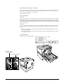
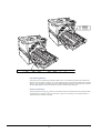
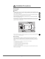


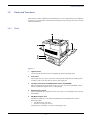
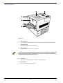
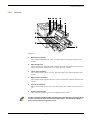
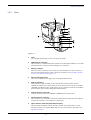

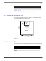


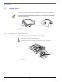
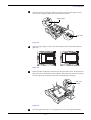
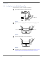
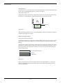
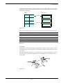
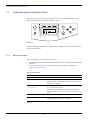
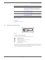
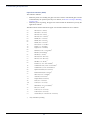
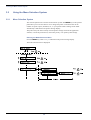
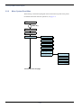

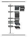
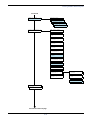

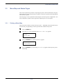

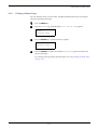
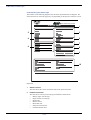
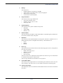

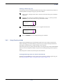
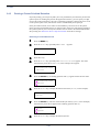
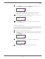
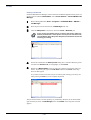
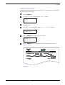

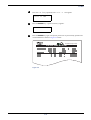
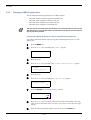

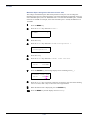
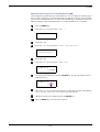
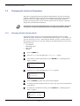
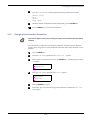

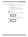

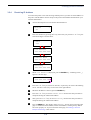
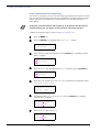
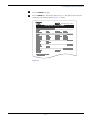

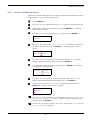
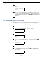
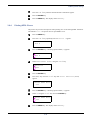
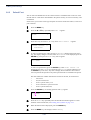

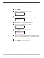
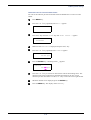

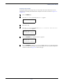
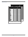
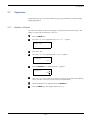
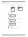
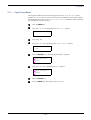
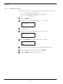
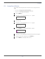
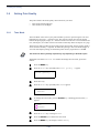
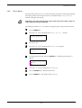
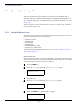
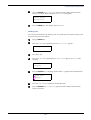
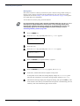
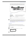
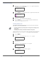
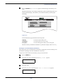
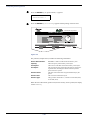

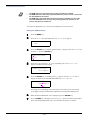


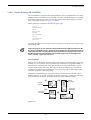
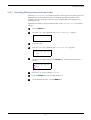
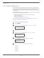
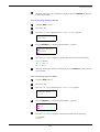
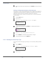
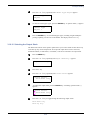
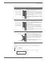
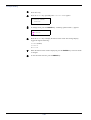
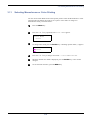
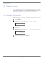
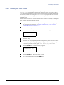
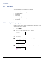
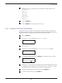
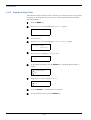
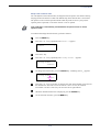

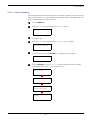
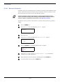
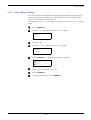
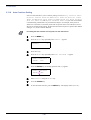
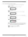
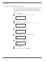
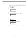
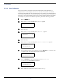

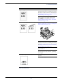
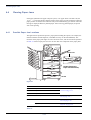

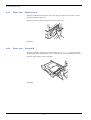
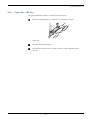
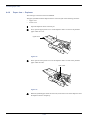

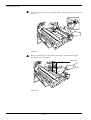
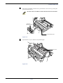
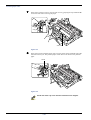
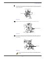
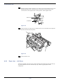
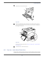
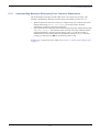
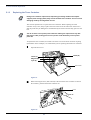
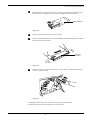
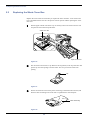
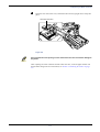
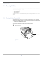
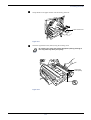


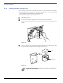

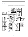
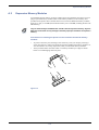
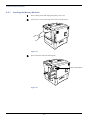
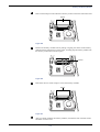
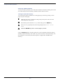
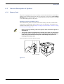
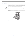
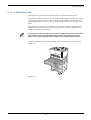
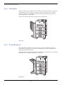
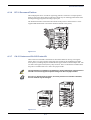
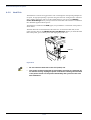
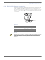
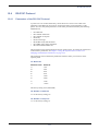


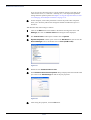
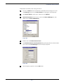


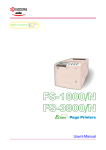
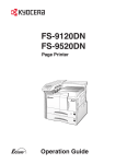
![[ok] ([enter]) - Triumph Adler](http://vs1.manualzilla.com/store/data/006356925_1-3a26b1d951f150d10c46554e4692dbf5-150x150.png)