1
FS-3820N
FS-3830N
Page Printers
Operation Guide
Caution on Installation
No liability is assumed for any damage caused by improper installation.
Notice on Software
Software used with this printer must support the printer’s emulation mode. The printer is factory-set to emulate the PCL. The emulation mode can be changed by following the procedures described in Chapter 1.
Notice on This Guide
The information in this guide is subject to change without notification. Additional pages may be inserted in future editions. The user
is asked to excuse any technical inaccuracies or typographical errors in the present edition.
No responsibility is assumed if accidents occur while the user is following the instructions in this guide. No responsibility is assumed
for defects in the printer’s firmware (contents of its read-only memory).
This guide, any copyrightable subject matter sold or provided with or in connection with the sale of the page printer, are protected by
copyright. All rights are reserved. Copying or other reproduction of all or part of this guide, any copyrightable subject matter without
the prior written consent of Kyocera Corporation is prohibited. Any copies made of all or part of this guide, any copyrightable subject
must contain the same copyright notice as the material from which the copying is done.
Regarding Tradenames
PRESCRIBE is a registered trademark of Kyocera Corporation. KPDL and KIR (Kyocera Image Refinement) are trademarks of
Kyocera Corporation.
Diablo 630 is a product of Xerox Corporation. IBM Proprinter X24E is a product of International Business Machines Corporation. Epson
LQ-850 is a product of Seiko Epson Corporation.
Hewlett-Packard, PCL, and PJL are registered trademarks of Hewlett-Packard Company. Centronics is a trade name of Centronics
Data Computer Inc. PostScript is a registered trademark of Adobe Systems Incorporated. Macintosh is a registered trademark of Apple
computer, Inc. Microsoft, Windows, and Windows NT are registered trademarks of Microsoft Corporation. PowerPC and Microdrive
are trademarks of International Business Machines Corporation. CompactFlash is a trademark of SanDisk Corporation. ENERGY
STAR is a U.S. registered mark. All other brand and product names are registered trademarks or trademarks of their respective
companies.
This Kyocera Mita page printer uses PeerlessPrintXL to provide the HP LaserJet compatible PCL6 language emulation. PeerlessPrintXL is a trademark of The Peerless Group, Redondo Beach, CA 90278, U.S.A.
This product was developed using the Tornado™ Real Time Operating System and Tools from Wind River Systems.
This product contains UFST™ and MicroType® from Agfa Monotype Corporation.
©2003, 2004 by KYOCERA MITA CORPORATION All rights reserved.
Revision 1.1 January 2004
i
IBM PROGRAM LICENSE AGREEMENT
The device you have purchased contains one or more software programs ("Programs") which belong to international business machines
corporation ("IBM"). This document defines the terms and conditions under which the software is being licensed to you by IBM. If you
do not agree with the terms and conditions of this license, then within 14 days after your acquisition of the device you may return the
device for a full refund. If you do not so return the device within the 14 days, then you will be assumed to have agreed to these terms
and conditions.
The Programs are licensed not sold. IBM, or the applicable IBM country organization, grants you a license for the Programs only in the
country where you acquired the Programs. You obtain no rights other than those granted you under this license.
The term "Programs" means the original and all whole or partial copies of it, including modified copies or portions merged into other
programs. IBM retains title to the Programs. IBM owns, or has licensed from the owner, copyrights in the Programs.
1. License
Under this license, you may use the Programs only with the device on which they are installed and transfer possession of the Programs
and the device to another party.
If you transfer the Programs, you must transfer a copy of this license and any other documentation to the other party. Your license is
then terminated. The other party agrees to these terms and conditions by its first use of the Program.
You may not:
1) use, copy, modify, merge, or transfer copies of the Program except as provided in this license;
2) reverse assemble or reverse compile the Program; or
3) sublicense, rent, lease, or assign the Program.
2. Limited Warranty
The Programs are provided "AS IS."
There are no other warranties covering the Programs (or conditions), express or implied, including, but not limited to, the implied
warranties of merchantability and fitness for a particular purpose.
Some jurisdictions do not allow the exclusion of implied warranties, so the above exclusion may not apply to you.
3. Limitation of Remedies
IBM’s entire liability under this license is the following;
1) For any claim (including fundamental breach), in any form, related in any way to this license, IBM’s liability will be for actual
damages only and will be limited to the greater of:
a) the equivalent of U.S.$25,000 in your local currency; or
b) IBM’s then generally available license fee for the Program
This limitation will not apply to claims for bodily injury or damages to real or tangible personal property for which IBM is legally liable.
IBM will not be liable for any lost profits, lost savings, or any incidental damages or other economic consequential damages, even if
IBM, or its authorized supplier, has been advised of the possibility of such damages. IBM will not be liable for any damages claimed by
you based on any third party claim. This limitation of remedies also applies to any developer of Programs supplied to IBM. IBM’s and
the developer’s limitations of remedies are not cumulative. Such developer is an intended beneficiary of this Section. Some jurisdictions
do not allow these limitations or exclusions, so they may not apply to you.
4. General
You may terminate your license at any time. IBM may terminate your license if you fail to comply with the terms and conditions of this
license. In either event, you must destroy all your copies of the Program. You are responsible for payment of any taxes, including
personal property taxes, resulting from this license. Neither party may bring an action, regardless of form, more than two years after
the cause of action arose. If you acquired the Program in the United States, this license is governed by the laws of the State of New York.
If you acquired the Program in Canada, this license is governed by the laws of the Province of Ontario. Otherwise, this license is
governed by the laws of the country in which you acquired the Program.
ii
Typeface Trademark Acknowledgement
All resident fonts in this printer are licensed from Agfa Corporation.
Helvetica, Palatino and Times are registered trademarks of Linotype-Hell AG.
ITC Avant Garde Gothic, ITC Bookman, ITC ZapfChancery and ITC Zapf Dingbats are registered trademarks of International Typeface Corporation.
Agfa Japan License Agreement
1. “Software” shall mean the digitally encoded, machine readable, scalable outline data as encoded in a special format as well as the
UFST Software.
2. You agree to accept a non-exclusive license to use the Software to reproduce and display weights, styles and versions of letters,
numerals, characters and symbols (“Typefaces”) solely for your own customary business or personal purposes at the address stated
on the registration card you return to Agfa Japan. Under the terms of this License Agreement, you have the right to use the Fonts
on up to three printers. If you need to have access to the fonts on more than three printers, you need to acquire a multi-user license
agreement which can be obtained from Agfa Japan. Agfa Japan retains all rights, title and interest to the Software and Typefaces
and no rights are granted to you other than a License to use the Software on the terms expressly set forth in this Agreement.
3. To protect proprietary rights of Agfa Japan, you agree to maintain the Software and other proprietary information concerning the
Typefaces in strict confidence and to establish reasonable procedures regulating access to and use of the Software and Typefaces.
4. You agree not to duplicate or copy the Software or Typefaces, except that you may make one backup copy. You agree that any such
copy shall contain the same proprietary notices as those appearing on the original.
5. This License shall continue until the last use of the Software and Typefaces, unless sooner terminated. This License may be
terminated by Agfa Japan if you fail to comply with the terms of this License and such failure is not remedied within thirty (30)
days after notice from Agfa Japan. When this License expires or is terminated, you shall either return to Agfa Japan or destroy all
copies of the Software and Typefaces and documentation as requested.
6. You agree that you will not modify, alter, disassemble, decrypt, reverse engineer or decompile the Software.
7. Agfa Japan warrants that for ninety (90) days after delivery, the Software will perform in accordance with Agfa Japan-published
specifications, and the diskette will be free from defects in material and workmanship. Agfa Japan does not warrant that the
Software is free from all bugs, errors and omissions.
The parties agree that all other warranties, expressed or implied, including warranties of fitness for a particular purpose and
merchantability, are excluded.
8. Your exclusive remedy and the sole liability of Agfa Japan in connection with the Software and Typefaces is repair or replacement
of defective parts, upon their return to Agfa Japan.
In no event will Agfa Japan be liable for lost profits, lost data, or any other incidental or consequential damages, or any damages
caused by abuse or misapplication of the Software and Typefaces.
9. New York, U.S.A. law governs this Agreement.
10. You shall not sublicense, sell, lease, or otherwise transfer the Software and/or Typefaces without the prior written consent of Agfa
Japan.
11. Use, duplication or disclosure by the Government is subject to restrictions as set forth in the Rights in Technical Data and Computer
Software clause at FAR 252-227-7013, subdivision (b)(3)(ii) or subparagraph (c)(1)(ii), as appropriate. Further use, duplication or
disclosure is subject to restrictions applicable to restricted rights software as set forth in FAR 52.227-19 (c)(2).
12. You acknowledge that you have read this Agreement, understand it, and agree to be bound by its terms and conditions. Neither
party shall be bound by any statement or representation not contained in this Agreement. No change in this Agreement is effective
unless written and signed by properly authorized representatives of each party. By opening this diskette package, you agree to
accept the terms and conditions of this Agreement.
Cautions for Toner Handling
•
Do not incinerate toner and toner containers. Dangerous sparks may cause burn.
•
Never open the toner container or waste toner box.
•
Make sure not to inhale the toner, and not to rub your eyes or touch your mouth with the hands stained with the toner. And make
sure not to stick to your skin.
•
For the disposal of old toner container and waste toner box, consult your dealer. Or dispose of the toner or toner containers in
accordance with Federal, state and Local rules and regulations.
•
Keep away the toner container and the waste toner box from children.
iii
Contents
Contents
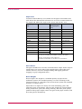
Introduction ................................................................................................ ix
Features ........................................................................................................................................................... x
For More Information... ................................................................................................................................ xiii
Guide to the Operation Guide...................................................................................................................... xiv
Chapter 1
Using the Operator Panel ....................................................... 1-1
Understanding the Operator Panel ............................................................................................................. 1-2
Message Display .................................................................................................................................... 1-2
Interface Indicator ................................................................................................................................. 1-3
Paper Size Indicator............................................................................................................................... 1-3
Paper Type Indicator ............................................................................................................................. 1-4
READY, DATA, and ATTENTION Indicators ...................................................................................... 1-4
Keys ........................................................................................................................................................ 1-5
Menu System Road Map........................................................................................................................ 1-6
Printing Test Pages .................................................................................................................................... 1-12
Menu Map ............................................................................................................................................ 1-12
Status Page........................................................................................................................................... 1-14
Service Status Page ............................................................................................................................. 1-18
Network Interface Status Page ........................................................................................................... 1-19
Font Lists.............................................................................................................................................. 1-21
Received Data Dumping ...................................................................................................................... 1-23
Paper Handling........................................................................................................................................... 1-24
Setting the Paper Size ......................................................................................................................... 1-24
Setting the Paper Size in Paper Cassette ............................................................................ 1-24
Setting the Paper Size in MP Tray ....................................................................................... 1-28
Setting the Paper Type ........................................................................................................................ 1-30
Setting the Paper Type in Paper Cassette ........................................................................... 1-30
Setting the Paper Type in MP Tray ..................................................................................... 1-31
Creating Custom Paper Type ............................................................................................... 1-32
Resetting the Custom Paper Type ........................................................................................ 1-36
MP Tray Mode...................................................................................................................................... 1-37
Selecting the Paper Feed Source ......................................................................................................... 1-38
Selecting the Output Stack ................................................................................................................. 1-39
Overriding A4 and Letter Size Difference .......................................................................................... 1-40
iv
Contents
Pagination ................................................................................................................................................... 1-41
Emulation............................................................................................................................................. 1-41
Changing the Emulation ...................................................................................................... 1-41
Alternative Emulation for KPDL Emulation ...................................................................... 1-42
Printing KPDL Errors .......................................................................................................... 1-43
Font ....................................................................................................................................................... 1-44
Default font ............................................................................................................................ 1-44
Default Font Size ................................................................................................................... 1-46
Changing Type for Courier/Letter Gothic ............................................................................ 1-47
Setting the Character Pitch for Courier/Letter Gothic ....................................................... 1-48
Code Set................................................................................................................................................ 1-49
Number of Copies................................................................................................................................. 1-50
Printing Orientation ............................................................................................................................ 1-51
KIR (Kyocera Image Refinement) ....................................................................................................... 1-52
Ecoprint ................................................................................................................................................ 1-54
Resolution............................................................................................................................................. 1-55
e-MPS .......................................................................................................................................................... 1-56
Quick Copy ........................................................................................................................................... 1-57
Proof and Hold ..................................................................................................................................... 1-59
Printing a Private Job ......................................................................................................................... 1-61
Printing a Stored Job........................................................................................................................... 1-63
Printing a Code Job ............................................................................................................................. 1-65
Printing a List of Code Jobs ................................................................................................................ 1-67
Retrieving Jobs from Virtual Mailbox (VMB) .................................................................................... 1-68
Printing a List of VMB ........................................................................................................................ 1-69
e-MPS Configuration ........................................................................................................................... 1-70
Interface ...................................................................................................................................................... 1-74
Parallel Interface Mode ....................................................................................................................... 1-74
USB Interface Mode............................................................................................................................. 1-75
Serial Interface Parameters ................................................................................................................ 1-76
Network Interface Parameters............................................................................................................ 1-78
Operating the Storage Device .................................................................................................................... 1-81
Activating the RAM Disk .................................................................................................................... 1-81
Reading Data ....................................................................................................................................... 1-83
Writing Data......................................................................................................................................... 1-84
Deleting Data ....................................................................................................................................... 1-86
Reading Fonts from a CompactFlash Card ........................................................................................ 1-87
Formatting a Storage Device............................................................................................................... 1-88
Printing a List of Data Names ............................................................................................................ 1-89
v
Contents
Configuration .............................................................................................................................................. 1-91
Page Protect Mode ............................................................................................................................... 1-91
Linefeed (LF) Action ............................................................................................................................ 1-92
Carriage-Return (CR) Action .............................................................................................................. 1-93
Wide A4 Pitch....................................................................................................................................... 1-94
Print Density........................................................................................................................................ 1-95
Total Printed Pages.............................................................................................................................. 1-96
Toner Counter Resetting ..................................................................................................................... 1-96
Message Language............................................................................................................................... 1-97
Automatic Form Feed Timeout............................................................................................................ 1-99
Sleep Timer Setting ........................................................................................................................... 1-100
Printer Resetting ............................................................................................................................... 1-102
Resource Protection ........................................................................................................................... 1-103
Alarm (Buzzer) Setting...................................................................................................................... 1-104
Auto Continue Setting ....................................................................................................................... 1-105
Duplex Printing Error Detection Setting ......................................................................................... 1-107
Chapter 2
Paper Selection....................................................................... 2-1
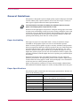
General Guidelines....................................................................................................................................... 2-2
Paper Availability .................................................................................................................................. 2-2
Paper Specifications............................................................................................................................... 2-2
Selecting the Right Paper ...................................................................................................................... 2-3
Special Paper ................................................................................................................................................ 2-7
Transparency (Overhead Projection Film) ........................................................................................... 2-7
Adhesive-Backed Labels ........................................................................................................................ 2-8
Paper Type .................................................................................................................................................. 2-12
Chapter 3
Maintenance ........................................................................... 3-1
Toner Container Replacement ..................................................................................................................... 3-2
Toner Container Replacement Interval ................................................................................................ 3-2
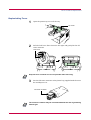
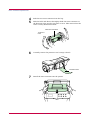
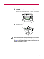
Replenishing Toner ................................................................................................................................ 3-3
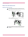
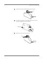
Waste Toner Box Replacement .................................................................................................................... 3-6
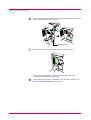
Replacing the Waste Toner Box............................................................................................................. 3-6
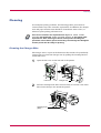
Cleaning ........................................................................................................................................................ 3-9
Cleaning the Charger Wire ................................................................................................................... 3-9
Cleaning the Charger Grid.................................................................................................................. 3-10
Paper Transfer Unit............................................................................................................................. 3-13
vi
Contents
Chapter 4
Troubleshooting ...................................................................... 4-1
General Guide............................................................................................................................................... 4-2
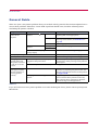
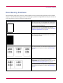
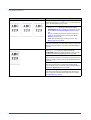
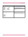
Print Quality Problems ................................................................................................................................ 4-3
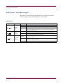
Indicators and Messages .............................................................................................................................. 4-6
Indicators................................................................................................................................................ 4-6
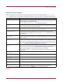
Maintenance Messages.......................................................................................................................... 4-7
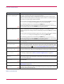
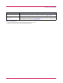
Error Messages .................................................................................................................................... 4-10
Correcting a Paper Jam.............................................................................................................................. 4-12
Jam at the Paper Cassette or Inside the Printer ............................................................................... 4-14
Paper Jam at the Option Duplexer ..................................................................................................... 4-16
Paper Jam at the Option Sorter .......................................................................................................... 4-18
Jam at the MP Tray............................................................................................................................. 4-20
Chapter 5
Fonts ....................................................................................... 5-1
List of Fonts .................................................................................................................................................. 5-2
PCL (Scalable and Bitmap) Fonts......................................................................................................... 5-2
KPDL Fonts (1) ...................................................................................................................................... 5-5
KPDL Fonts (2) ...................................................................................................................................... 5-6
Appendix A
Options .................................................................................... A-1
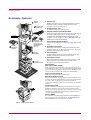
Available Options .........................................................................................................................................A-2
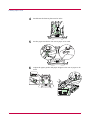
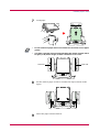
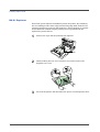
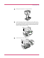
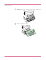
Expanding the Printer Memory...................................................................................................................A-3
Installing Option Units ................................................................................................................................A-9
PF-60 Paper Feeder ................................................................................................................................A-9
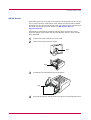
DU-61 Duplexer ...................................................................................................................................A-12
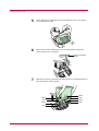
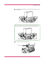
SO-60 Sorter.........................................................................................................................................A-15
EF-60 Envelope Feeder ........................................................................................................................A-21
PT-4/PT-60 Rear Tray .........................................................................................................................A-25
Network Interface Card.......................................................................................................................A-26
Microdrive (Hard Disk)........................................................................................................................A-28
CompactFlash (Memory) Card ............................................................................................................A-30
Appendix B
Host Computer Interface ........................................................ B-1
Parallel Interface ......................................................................................................................................... B-2
Parallel Interface Communication Modes ........................................................................................... B-2
Interface Signals ................................................................................................................................... B-2
USB Interface .............................................................................................................................................. B-5
Specifications ........................................................................................................................................ B-5
Interface Signals ................................................................................................................................... B-5
vii
Contents
Serial Interface (Option) ............................................................................................................................. B-6
RS-232C Interface................................................................................................................................. B-6
RS-232C Protocol ......................................................................................................................................... B-7
PRESCRIBE FRPO D0 Command....................................................................................................... B-9
RS-232C Cable Connection ....................................................................................................................... B-10
Obtain a Suitable RS-232C Cable...................................................................................................... B-10
Connecting the Printer to the Computer........................................................................................... B-10
Appendix C
Specifications ......................................................................... C-1
Glossary ....................................................................................... Glossary-1
Index ................................................................................................. Index-1
viii
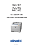
Introduction
The Kyocera Mita page printer has many extremely desirable features. It was designed to
make a contribution to a cleaner environment as well as to represent the latest generation of
page printer technology.
This section contains the following subsections.
•
•
•
Features
For More Information...
Guide to the Operation Guide
ix
Features
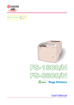
This section outlines the common major printer features of the FS-3830N
page printer.
Ultra long life modules
The drum, developer, and fuser have been designed for ultra long life.
Amorphous silicon drum
The drum has been developed using Kyocera’s unique ceramic technology
using amorphous silicon.
KIR (Kyocera Image Refinement)
This is Kyocera’s original smoothing function. It uses software to enhance
the printer’s resolution and produce high-quality printing. The default
setting is On.
Superb print quality
Using 1200 dpi resolution in Fast 1200 mode or Fine 1200 mode, the
printout is close to typeset quality. Also, with Kyocera Image Refinement
(KIR) technology, high quality printing can be achieved even at 300 dpi and
600 dpi.
Large paper capacity
Approximately 500 sheets can be loaded into the paper cassette, and about
100 sheets can be loaded into the MP tray.
Wide variety of print media
As well as standard paper, the printer will print on transparency, labels
and other types of special purpose media.
Sleep Mode
Conserves energy during the printer’s idle periods.
Ecoprint
Extends the toner yield by reducing the amount of toner used on the page.
Displaying printer messages in any of eight languages
Printer messages can be displayed in English, French, German, Italian,
Dutch, Spanish, or Portuguese.
x
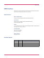
USB (Universal Serial Bus) Interface
This printer supports Hi-Speed USB 2.0 standards. Connection to a
computer with a USB interface gives a higher communication speed than
parallel interface connection.
e-MPS
‘e-MPS’ is an abbreviation for ‘enhanced-Multiple Printing System,’ which
is a post-processing function that combines electronic sorting, job
retention, and virtual mailboxing.
When printing multiple copies of a document, the data is transferred from
the computer to the printer only for the first copy; the data is then stored
on the printer’s hard disk. Copies of the document are printed using the
stored data.
Printing is performed faster with less computer spooling time and less
network traffic.
Furthermore, printed data that is stored on the hard disk can be called up
using job retention functions, such as Quick Copy etc., allowing you to
quickly print additional copies of a document from the printer at any time,
without needing to re-spool the document or start up the computer system.
Printer control language PRESCRIBE
The printer uses PRESCRIBE, Kyocera Mita’s page printer control
language with enhanced color graphics capabilities. The simple commands
of PRESCRIBE allow the programmers to easily define pagination and
device control.
KPDL3 (Kyocera Printer Description Language 3)
KPDL3 is the Kyocera’s implementation of the PostScript page description
language Level 3. The printer has 80 fonts that are compatible with Adobe
PostScript fonts. (The printer also has 80 PCL fonts.)
PDF direct printing
Allows you to send a selected PDF (version 1.4 or less) file directly to the
printer without invoking a printer driver.
Account management system
The account management system function records the number of pages
printed by each department. The administrator can preset the maximum
number of pages that each department will be allowed to print.
xi
Microdrive (hard disk unit) slot for various functions such as job
retention, VMB, and more
By saving print jobs onto the Microdrive, they can be printed out at the
operator panel when desired. The electronic sort function can be used for
much faster printing.
CompactFlash card slot for option fonts, macros, forms, etc.
Data in the CompactFlash card can be selectively read from the printer’s
operator panel.
SNMP compliance
The printer complies with Simple Network Management Protocol (SNMP).
The SNMP is used for providing and transferring management information
(MIB) between the printer and the host computer.
Built-in and external network interfaces
Because the network interface supports TCP/IP, IPX/SPX, NetBEUI and
EtherTalk protocols, network printing is possible with various
environments including Windows, Macintosh, UNIX and NetWare, etc.
Support for network printer monitor utility (KM-NET VIEWER)
Allows network wide management of printers. See the readme file in the
CD-ROM (comes with the printer) for details.
xii
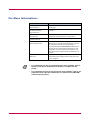
For More Information...
Item
Description
Installation Guide
(paper manual)
Describes procedures from printer setup to printing
a test page.
KX Printer Driver
Installation Guide
(paper manual)
Describes the procedure to install the printer driver
software.
Operation Guide
(this manual)
Guides you through topics concerning the
operations and maintenance of the printer.
KX Printer Drivers
Operation Guide
Describes how to install and set the printer driver.
PRESCRIBE Command
Technical Reference
PRESCRIBE is the native language of the Kyocera
Mita printers. This Technical Reference contains
the information about how the printing is
performed using the PRESCRIBE commands as
well as the font and emulation description. Also
included is a list of permanent parameters and
their explanation needed when customizing your
printer.
PRESCRIBE Command
Reference
Gives a detailed explanation of the PRESCRIBE
command syntax and parameters with the aid of
print examples.
•
For information on how to install the printer driver software, refer to
the KX Printer Driver Installation Guide that is included with the
printer.
•
For information on how to use the printer driver software, refer to the
KX Printer Driver Operation Guide that is included on the CD-ROM
(comes with the printer).
Note
xiii
Guide to the Operation Guide
This Operation Guide has the following chapters:
Chapter 1
Using the Operator Panel
This chapter explains the message display, indicators and keys on the
operator panel, and how to make various settings from the operator panel.
Chapter 2
Paper Selection
This chapter explains the types of paper that can be used with the printer.
Chapter 3
Maintenance
This chapter explains how to replace the toner container, waste toner box,
and how to care for your printer.
Chapter 4
Troubleshooting
This chapter explains how to handle printer problems that may occur, such
as paper jams.
Chapter 5
Fonts
This chapter explains about fonts and lists the printer’s internal fonts.
Appendix A Options
This appendix explains how to expand the printer’s memory and how to
install each option unit.
Appendix B
Host Computer Interface
This appendix explains the pin assignment and specifications for the
printer’s parallel interface, USB interface, and option serial interface.
Appendix C
Specifications
This appendix lists the printer’s specifications.
Glossary
This glossary explains the terminology used in this guide.
The following symbols are used to attract your attention in this guide. The
symbols and their meanings are as follows:
xiv
Indicates tips or advice useful for operation.
Note
Indicates situations that are potentially hazardous to the human body or
devices.
Caution
Indicates situations that are potentially extremely hazardous to the
human body or devices.
Warning
Indicates operations that can be performed or are effective only when the
required option unit is installed.
Option
xv
Chapter 1
Using the Operator
Panel
1
This chapter explains the following topics:
•
•
•
•
•
•
•
•
Understanding the Operator Panel
Printing Test Pages
Paper Handling
Pagination
e-MPS
Interface
Operating the Storage Device
Configuration
1-1
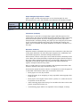
Understanding the Operator Panel
Understanding the Operator Panel
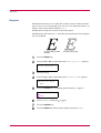
The operator panel has a LCD message display, three indicators, and eight
keys.
Messages that appear on the display and functions of indicators and keys
are explained in the sections that follows.
Message Display
The message display gives information in the form of short messages. The
eight messages listed below are displayed during normal warm-up and
printing.
Other messages that may appear when the printer needs the operator’s
attention are explained in Chapter 4.
Message
Meaning
Self test
The printer is self-testing after power-up.
Please wait
The printer is warming up and is not ready. When
the printer is switched on for the first time after the
toner container is installed, (Adding toner)
also appears.
Ready
The printer is ready to print.
Processing
The printer is receiving data, generating graphics,
reading a CompactFlash card/Microdrive, or
printing.
Sleeping
The printer is in sleep mode. The printer wakes
from sleep mode whenever the GO key on the
operator panel is pressed, the cover is opened or
closed, or data is received. The printer then warms
up and goes online. The time that the printer takes
to enter sleep mode depends on the sleep timer
setting.
Cancelling data
Jobs inside the printer are being canceled. To cancel
a job, see the table on page 1-5.
Waiting
The printer is waiting for the end-of-job command
before printing the last page. Pressing the GO key
allows you to obtain the last page immediately.
FormFeed Time Out
The printer is printing the last page after a waiting
period.
Table 1-1
1-2
Understanding the Operator Panel
INTERFACE
Interface Indicator
The interface indicator shows the interface that is currently used. It uses
the following abbreviations:
PAR
USB
NET
SER
OPT
---
Note
Standard bi-directional parallel interface
Standard USB interface
Network interface
Option serial interface (RS-232C)
Option network interface card
No interface is active.
Each interface has a timeout time of 30 seconds during which the other
interface should wait to receive a print job. Even a print job has been
complete on the interface, you should wait for this period until the other
interface begins printing the job.
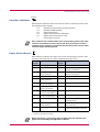
SIZE
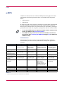
Paper Size Indicator
This indicator indicates the paper size of the current paper cassette. The
following abbreviations are used to indicate the paper sizes.
Message
Display
Paper Size
Message
Display
Paper Size
A4
ISO A4 (21 × 29.7 cm)
EX
Executive (7-1/4 × 10-1/2 inches)
A5
ISO A5 (14.8 × 21 cm)
#6
Commercial 6-3/4
(3-5/8 × 6-1/2 inches)†
A6
ISO A6
(10.5 × 14.8 cm)†
#9
Commercial 9
(3-7/8 × 8-7/8 inches)†
B5
JIS B5 (18.2 × 25.6 cm) O2
Oficio II (8-1/2 × 13 inches)
B6
JIS B6
(12.8 × 18.2 cm)†
16K
16 kai (19.7 × 27.3 cm)
LT
Letter
(8-1/2 × 11 inches)
ST
Statement (5-1/2 × 8-1/2 inches)†
LG
Legal
(8-1/2 × 14 inches)
FO
Folio (21 × 33 cm)
MO
Monarch
(3-7/8 × 7-1/2 inches)†
HA
Japanese Postcard (10 × 14.8 cm)†
BU
Business
(4-1/8 × 9-1/2 inches)†
OH
Return Postcard (20 × 14.8 cm)†
DL
ISO DL (11 × 22 cm)†
Y2
Envelope (Youkei 2)
(11.4 × 16.2 cm)†
C5
ISO C5
(16.2 × 22.9 cm)
Y4
Envelope (Youkei 4)
(10.5 × 23.5 cm)†
b5
ISO B5 (17.6 × 25 cm)
CU
Custom Size
(14.8 × 21 cm to 21.6 × 35.6 cm)
Table 1-2
†
With only the MP tray feeding.
While the printer is processing data, the SIZE indicator indicates the
paper size selected by the application software.
Note
1-3
Understanding the Operator Panel
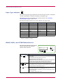
TYPE
Paper Type Indicator
This shows the paper type defined for the current paper casette. Automatic
cassette switching is available according to the paper type.
The paper type can be specified at the operator panel. See Creating
Custom Paper Type on page 1-32.
The following abbreviations are used to indicate the paper type.
Message Display
Paper Type
Message Display
Paper Type
None
Auto
LETTERHEA
Letterhead
PLAIN
Plain
COLOR
Color
†
TRNSPRNCY
Transparency
PREPUNCHE
Prepunched
PREPRINTE
Preprinted
ENVELOPE
Envelope†
LABELS
Labels†
CARDSTOCK
Cardstock†
BOND
Bond
THICK
Thick†
RECYCLED
Recycled
HIGH QUAL
High quality
VELLUM
Vellum†
CUSTOM 1 (to 8)
Custom 1 (to 8)
ROUGH
Rough
Table 1-3
†
With only the MP tray feeding.
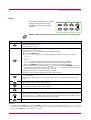
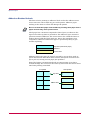
READY, DATA, and ATTENTION Indicators
The following indicators light during
normal operation and when the
printer needs attention.
READY
Ready
PAR A4 PLAIN
DATA
ATTENTION
INTERFACE SIZE
Indicator
TYPE
Description
READY
DATA
ATTENTION
Flashing: Indicates when an error occurs that you can clear
by yourself.
Lit: Indicates that the printer is on-line.
The printer prints received data.
Off: Indicates that the printer is off-line. Data can be received
but will not be printed. Also indicates when printing is
automatically stopped due to occurrence of an error.
Flashing: Indicates data transfer is taking place.
Lit: Indicates either that data is being processed, or that data
is being written to the memory card.
Flashing: Indicates when the printer needs maintenance
attention or the printer is warming up (Please wait).
Lit: Indicates when a problem or an error occurs that you can
clear by yourself.
(For example, paper jam occurs.)
Table 1-4
1-4
Understanding the Operator Panel
Keys
The operator panel keys are used to
configure the printer. Note the
certain keys have the secondary
function.
GO
CANCEL
?
MENU
ENTER
Settings made with these keys effect only the interface currently in use.
Note
Key
Function
• Switches the printer on-line and off-line.
• Prints and feed out one page.
• Cancels specific errors.
GO
• Cancels a printing job.
To cancel, proceed as follows:
1 Check if Processing is displayed in the message display.
2 Press the CANCEL key.
3 Print Cancel? appears in the message display and then interface to be canceled.
Parallel
USB
Network
Serial (appears only when an option serial interface board kit is installed)
Option (appears only when an option network interface card is installed)
Press the CANCEL key again if you wish to stop the cancellation of printing.
4 Select the interface to cancel using the or key and then press the ENTER key. Printing
from the selected interface will stop. Cancelling data appears in the message display
CANCEL
and printing stops after the current page is printed.
• Resets numeric values, or cancels a setting procedure.
• Used to stop the sounding of the alarm buzzer an error occurs.
†
MENU
• When pressed during mode selection, terminates the setting and the printer returns to the
Ready condition.
• Used to select the emulation, font, character code set; to read an CompactFlash card, and
more.
Used to access a desired item or enter numeric values. In some of the control procedures, the >
and < keys are used to enter or exit a sub item.
Used to access a desired item or enter of numeric values. In some of the control procedures, the
> and < keys are used to enter or exit a sub item.
Used as the < key in the mode selection function.
• Used as the > key in the mode selection function.
• Displays online help messages on the message display when paper jam errors occur. When
pressed in the Ready condition, displays explanations of online help messages. When pressed
while the online help is displayed, cancels the online help.
?
†
Finalizes numeric values and other selections.
ENTER
Table 1-5
†
If you hold down the ENTER key and press the MENU key when Ready is shown on this printer, the AdministrationID menu
will be displayed. This menu is the setting menu for administration under the Account Management System and is normally not
used. Press the MENU key to return to the Ready display.
1-5
Understanding the Operator Panel
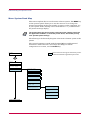
Menu System Road Map
This section explains how to use the menu selection system. The MENU key
on the operator panel allows you to use the menu to set or change the
printer environment such as the number of copies to make, emulation, etc.,
to your specific needs. Settings can be made when Ready is indicated on
the printer message display.
Note
The printer obeys the most recently received printer settings sent from
the application software, or from the printer driver, which take priority
over operator panel settings.
The following is the hierarchy diagram of the menu selection system of the
printer.
The vertical transition is made with the and keys and horizontal
transition is made with the > and < keys. To change or finalize
configuration on an item, use the ENTER key.
These items will not appear unless the printer
is installed with the applicable option unit.
Ready
PAR A4 PLAIN
MENU
Print
Menu Map
Print
Status Page
e-MPS
>
>Quick Copy
>Private/Stored
>Print VMB Data
>List of VMB
>List of
Code JOB
>e-MPS
>
Configuration
>>Quick Copy
>>Temp.Code JOB
Size
>>Perm.Code JOB
Size
>>VMB Size
Continued on next page
1-6
Understanding the Operator Panel
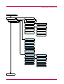
Continued from previous page
Interface
>
Parallel
USB
Interface
Network
Interface
Serial
Interface
Option
>
>
>
>Parallel I/F
Auto
Normal
High Speed
Nibble (high)
>NetWare
Off
>NetWare
On
>
>TCP/IP
Off
On
>>NetWare Frame
Auto
>>DHCP
OFF
>Ether Talk
Off
>>IP Address
>Network Status
Page
On
>>Subnet Mask
>>Gateway
>Baud Rate
9600
>Data Bits
8
>Stop Bits
1
>Parity
None
>Protocol
DTR (pos.)&XON
>NetWare
Off
>NetWare
On
>
>TCP/IP
Off
On
>>NetWare Frame
Auto
>>DHCP
OFF
>Ether Talk
Off
>>IP Address
>OPT. StatusPage
Off
>>Subnet Mask
>>Gateway
Continued on next page
1-7
Understanding the Operator Panel
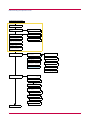
Continued from previous page
Emulation
PCL 6
Emulation
KPDL
>
>Print KPDL errs
Off
On
Emulation
KPDL (AUTO)
>
>Alt. Emulation
PCL 6
Emulation
Line Printer
>Print KPDL errs
Off
On
Emulation
IBM Proprinter
Emulation
DIABLO 630
Emulation
EPSON LQ-850
Font
>
Font Select
Internal
Option
>
>
>> I000
>Code Set
IBM PC-8
>>Courier
Dark
Regular
>List of
Internal Fonts
>>Letter Gothic
Regular
Dark
>List of
Option Fonts
>>Size
012.00
>>Pitch
Page Set
>
>Copies
001
>Orientation
Portrait
Landscape
>Page Protect
Auto
On
>LF Action
LF only
CR and LF
Ignore LF
>CR Action
CR only
CR and LF
Ignore CR
>Wide A4
Off
On
Continued on next page
1-8
10.00 cpi
Understanding the Operator Panel
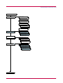
Continued from previous page
Print Quality
>
>KIR Mode
On
Off
>Ecoprint Mode
Off
On
>Resolution
Fast 1200 mode
Fine 1200 mode
300 dpi
600 dpi
>Print Density
03
Hard Disk
>
RAM Disk Mode
Off Disk Mode
RAM
On
Memory Card
>Read Data
>Write Data
>Delete Data
>List of
Partitions
>RAM Disk Size
>Read Data
>Write Data
>Delete Data
>List of
Partitions
>
>Read Fonts
>Read Data
>Write Data
>Delete Data
>Format
>List of
Partitions
Continued on next page
1-9
Understanding the Operator Panel
Continued from Previous page
Paper Handling >
>MP Tray Mode
Cassette
>MP Tray Size
A4 or Letter
>MP Tray Type
Plain
>EF Size
DL or Business
>EF Type
Envelope
>BulkFeeder Size
A4
>BulkFeeder Type
Plain
†
†
>Cassette Size
A4
>Cassette Size >
Custom
>Cassette Type
Plain
>>Unit
mm
inch
>>X Dimension
>Feed Select
Cassette
>>Y Dimension
>Duplex Mode
None
>Stack Select
Top
tray
FaceDn
>Stack
Select
RearTray FaceUp
>Sorter Mode
Sorter
>Override A4/LT
Off
>Override
A4/LT
On
>Type Adjust
Custom 1
>Reset Type
Adjust
Life Counters
>
>
>>Paper weight
Normal 2
>>Duplex Path
Enable
Disable
>Total Print
0123456
>New Toner
Installed
Continued on next page
†
The option bulk paper feeder can only be installed on the FS-3830N.
1-10
Understanding the Operator Panel
Continued from previous page
Others
>
>MSG Language
English
>Form Feed
Time Out 030sec.
>Sleep Timer
>
015 min.
>Print HEX-DUMP
>>Sleep Mode
On
Off
>Printer Reset
>Resource Prot.
Off
Permanent
Perm / Temp
>Buzzer
On
Off
>Auto Continue >
Mode
On
Mode
Off
>>Auto Continue
Timer 030sec.
>Finishing
>
>>Duplex
Off
On
>Service
>
>>Print
Status Page
>>Print
Event Log
>>Developer
>>DRUM-CTRL
00
>>Drum
††
This menu is for service personnel.
1-11
††
††
††
Printing Test Pages
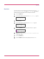
Printing Test Pages
This section explains the procedure for printing the printer’s internal
information using the menu selection system. The menu map is usefull as a
reference to guide yourself through the menu selection system.
The status page is a list of parameters and settings for most basic printer
configurations. You may be required to produce a status page when
requesting service to the printer.
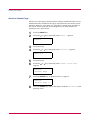
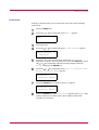
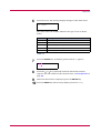
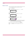
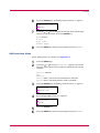
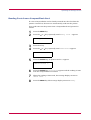
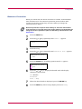
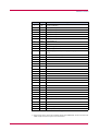
Menu Map
The printer prints a full list of menu selection system. Note that menus
indicated on the list may vary depending on which option units are
installed on the printer.
1
2
Press the MENU key.
Press the
or
key repeatedly until Print Menu Map appears.
Print
Menu Map
3
Press the ENTER key. A question mark (?) appears.
Print
Menu Map ?
4
Press the ENTER key again. The printer prints a menu map.
1-12
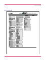
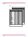
Printing Test Pages
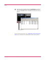
Sample MENU MAP
FS-3830N Page Printer
MENU MAP
1-13
Printing Test Pages
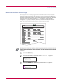
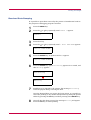
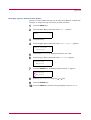
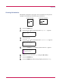
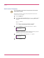
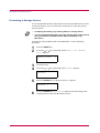
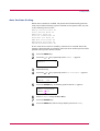
Status Page
If you want to check the printer's current status, including memory
available and option settings, you can find the information you need on the
status page.
1
2
Press the MENU key.
Press the
or
key repeatedly until Print Status Page appears.
Print
Status Page
3
Press the ENTER key. A question mark (?) appears.
Print
Status Page ?
4
Press the ENTER key again. The printer prints a status page.
For a full description of the status page, see the following pages.
1-14
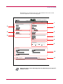
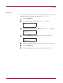
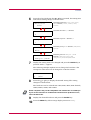
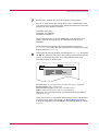
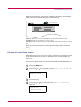
Printing Test Pages
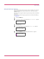
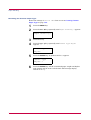
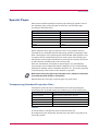
The following is a sample status page. The numbers below refer to the
contents explained on the following pages.
FS-3830N Page Printer
STATUS PAGE
Firmware Version:
Hardware Information
1
Released:
Memory
2
3
Page Information
4
6
Installed Options
5
Network Status
Emulation
7
8
Error Log
Toner Gauge
9
100
0
Interfaces
10
KIR Test pattern
ON
11
Items and values on the status page may vary depending on the printer’s
firmware version.
Note
1-15
Printing Test Pages
1 — Software Version
This information shows the firmware version and date of issue of the
printer.
2 — Hardware Information
This information shows various printer settings, such as the size and type
of the paper in the paper cassettes.
3 — Memory
This shows the amount of total memory installed in the printer, the
amount of currently available memory, and the current status of the RAM
disk. See Operating the Storage Device on page 1-81.
4 — Page Information
This shows the print resolution, number of copies, and the total page count.
5 — Installation Options
This shows the option(s) installed in the printer.
6 — Network Status
This shows the IP address, Subnet Mask address, and Default Gateway
address for the network interface card in the printer.
7 — Emulation
This shows all available emulations of the printer. The printer is shipped
from the factory with PCL 6 emulation selected as the default.
8 — Error Log
This shows the last three instances of the following types of errors, listing
them in the order of their occurrence:
•
KPDL (PostScript) errors
•
Memory card errors
•
Memory card, hard disk, RAM disk errors
The most recent error is displayed on the top line of the Error Log. For
error remedies, see section Error Messages on page 4-10. Error
information is cleared when the printer’s power is turned off.
9 — Toner Gauge
This shows the approximate level of remaining toner. When the value is
100, the toner container is full.
1-16
Printing Test Pages
10 — Interface Information
This information shows the default font and the default emulation for all
interfaces installed in the printer.
11 — KIR Test Pattern
KIR is the Kyocera Mita’s original smoothing function. This test pattern
shows the effect of the KIR (Kyocera Image Refinement) system.
1-17
Printing Test Pages
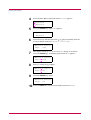
Service Status Page
The service status page contains printer settings information that is more
detailed than the standard status page and is therefore for mostly service
purposes. However, since there is a great deal of information available on
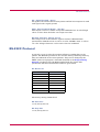
the service status page that may be helpful to you, the procedure for
printing it out is given below.
1
2
Press the MENU key.
Press the
or
key repeatedly until Others > appears.
Others
3
4
>
Press the > key.
Press the
or
key repeatedly until >Service > appears.
>Service
5
6
>
Press the > key.
Press the
appears.
or
key repeatedly until >>Print Status Page
>>Print
Status Page
7
Press the ENTER key. A question mark (?) appears.
>>Print
Status Page ?
8
Press the ENTER key again. The display indicates Processing and
printing starts.
1-18
Printing Test Pages
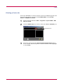
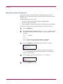
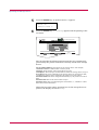
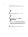
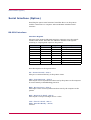
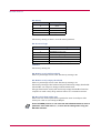
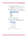
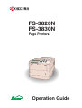
Network Interface Status Page
You can print out a status page for the network interface. The network
interface status page shows the firmware version, the network addresses,
and other information under various network protocols about the network
interface card. The default setting is Off (not print). If the setting is
changed to On (print) as follows, however, the network interface status
page will be printed when the printer status page is printed.
FS-3830N Page Printer
NETWORK STATUS PAGE
Note
Printing out a network interface status page may not be possible with the
option network interface card. For details, see the manual for the network
interface.
1
2
Press the MENU key.
Press the
or
key repeatedly until Interface > appears.
Interface
Parallel
3
>
Press the ENTER key. A blinking question mark (?) appears.
Interface
? Parallel
1-19
Printing Test Pages
4
Press the
or
key repeatedly until Network appears.
Interface
? Network
5
Press the ENTER key again. A > appears.
Interface
Network
6
>
Press the > key and then press the or key repeatedly until the
message display indicates >Network Status Page.
>Network Status
Page
Off
7
The default setting is Off. If it is set to On, change it as follows.
Press the ENTER key. A blinking question mark (?) appears.
>Network Status
Page ? Off
8
Select On using the
or
key.
>Network Status
Page ? On
9
Press the ENTER key again.
>Network Status
Page
On
10 Press the MENU key. The message display returns to Ready.
1-20
Printing Test Pages
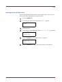
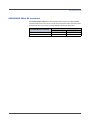
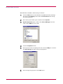
Font Lists
To help in selecting fonts, you can print the lists of the fonts including
option fonts.
1
2
Press the MENU key.
Press the
or
key repeatedly until Font > appears.
Font
3
4
>
Press the > key.
Press the
or
key repeatedly until > Font Select> appears.
>Font Select
Internal
>
5
To print a list of the internal fonts, check that Internal is
displayed. To print a list of option fonts, press the ENTER key. Press
the or key repeatedly until the message display indicates
Option and press the ENTER key.
6
Press the or key repeatedly until >List of Internal Fonts
or >List of Option Fonts appears.
>List of
Internal Fonts
7
Press the ENTER key. A question mark (?) appears.
>List of
Internal Fonts?
8
Press the ENTER key again. Processing appears, then Ready. The
printer prints a list of fonts with a short sample and font ID
(number) for each font.
1-21
Printing Test Pages
Font Lists
Internal Scalable and Bitmapped Fonts List
Font Name
Scalable/Bitmap
Password
Internal Scalable and Bitmapped Fonts List
Font Name
Scalable/Bitmap
1-22
Password
PRESCRIBE
Selection
PRESCRIBE
Selection
[FSET]
Font ID
[FSET]
Font ID
Printing Test Pages
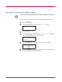
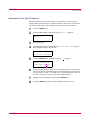
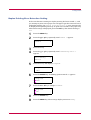
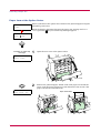
Received Data Dumping
It is possible to print data received by the printer as hexadecimal code for
the purposes of debugging programs and files.
1
2
Press the MENU key.
Press the
or
key repeatedly until Others > appears.
Others
3
4
>
Press the > key.
Press the
or
key repeatedly until > Print HEX-DUMP appears.
>Print HEX-DUMP
5
Press the ENTER key. A question mark (?) appears.
>Print HEX-DUMP?
6
Press the ENTER key again. Processing appears for a second, and
then Waiting appears.
Processing
Waiting
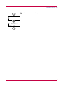
7
Send data to be dumped to the printer. The message Processing
will be displayed during receiving the data.
Once the dumped data you require has been output, it is possible to
cancel the printing of any further dumped data by taking the printer
offline by pressing the GO key and then pressing the CANCEL key.
8
Once all data has been received, the message Waiting will appear.
Press the GO key to finish printing.
1-23
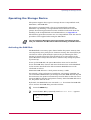
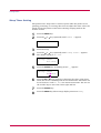
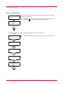
Paper Handling
Paper Handling
This section explains how to use the operator panel to change the paper
size and type for each paper source, the mode for the MP (multi-purpose)
tray, and other settings regarding paper handling.
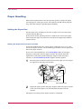
Setting the Paper Size
Set the paper sizes according to the sizes of paper to be set in the paper
cassette and the MP tray.
If they do not match, printing will not be made on the correct size paper
when automatic paper size selection is made by the application software
(printer driver).
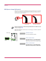
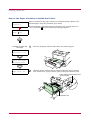
Setting the Paper Size in Paper Cassette
To set the standard sizes A5, A4, B5, Letter, and Legal (for U. S. A. only)
size for the paper cassette, use the following procedure to set the paper size
dial of the paper cassette.
If you use a non-standard size, see Custom Paper Size on next page.
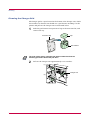
Properly set the paper into the paper cassette. For details about the
adjustment of the paper guides and paper stopper inside the paper
cassette, set the Installation Guide supplies with the printer.
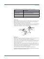
1
Turn the paper size dial so that the size of the paper you are going to
use appears in the paper size window.
Paper Size Dial
2
Paper Size Window
Adjust the paper guides and paper stopper inside the paper cassette
to the size of the paper to be used and load the paper into the
cassette.
The paper size setting for the paper cassette is completed.
1-24
Paper Handling
Custom Paper Size
In addition to the standard sizes A5, A4, B5, Letter, and Legal (for U. S. A.
only) size for the paper cassette, paper of other sizes can be fed as custom
sizes. When placing paper of sizes other than A5, A4, B5, Letter, or Legal
(for U. S. A. only) into the paper cassette, set the size of the paper to be
used into the printer by following the procedure given below. If an option
paper feeder (PF-60) is installed, custom sizes for its paper cassette can be
set using the same procedure.
This menu appears when the paper size dial of the paper cassette is set to
OTHER.
Properly set the paper into the paper cassette. For details about the
adjustment of the paper guides and paper stopper inside the paper
cassette, see the Installation Guide supplied with the printer.
Setting Paper Size Dial
Use the following procedure to set the paper size dial to OTHER.
1
Pull out the paper cassette from the printer and turn the paper size
dial to OTHER. See step 1 in Setting the Paper Size in Paper
Cassette.
2
Adjust the paper guides and paper stopper inside the paper cassette
to the size of the paper to be used and load the paper into the
cassette.
When using non-standard size paper, read the next section to set the
paper size from the operator panel.
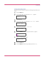
Setting a custom size from the Operator Panel
Set the size of the paper loaded in the paper cassette into the printer from
the printer operator panel.
1
2
Press the MENU key.
Press the
or
key repeatedly until Paper Handling > appears.
Paper Handling >
3
Press the > key.
1-25
Paper Handling
4
Press the
or
key repeatedly until >Cassette Size > appears.
If option paper feeders are added, Cassette 1 Size will appear for
the standard paper cassette and Cassette 2 Size, Cassette 3
Size, and Cassette 4 Size will appear for the option paper
feeders.
>Cassette Size >
Custom
5
Press the ENTER key. A blinking question mark (?) appears.
>Cassette Size
? Custom
6
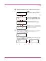
Press the or key to display the desired paper size. The message
display toggles through the following paper sizes:
Custom
Oficio II
Folio
16K
C5
A5
B5
ISO B5
A4
Executive
Letter
Legal
7
When the desired paper size is displayed, press the ENTER key. The
paper size is set for the paper cassette.
If you selected Custom in step 6, be sure to set the unit of
measurement and the dimensions of the paper as described in the
following sections.
1-26
Paper Handling
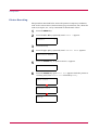
Selecting the Unit of Measurement
Then, use the following procedure to set the unit of measurement.
1
2
Press the > key.
Press the or key repeatedly until >>Unit appears. The unit of
measurement can be selected between millimeters and inches. The
current unit of measurement is displayed (the default setting is mm).
>>Unit
mm
3
Press the ENTER key. A blinking question mark (?) appears.
>>Unit
? mm
4
5
Select mm or inch using the
or
key.
Press the ENTER key.
Set the dimensions of paper as described in the next section.
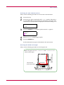
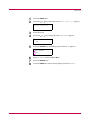
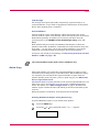
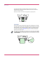
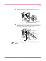
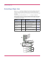
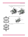
Entering the Width and Length
Then, use the following procedure to set the paper size.
148 to 216 mm
(5.83 to 8.5 inches)
1-27
X Dimension
210 to 356 mm
(8.27 to 14.02 inches)
Y Dimension
Enter the paper size for X Dimension and Y Dimension as
shown in the figure.
Paper Handling
1
When the unit of measurement is set, press the key.
>>X Dimension appears as shown below (the paper width setting).
>>X Dimension
216 mm
2
Press the ENTER key. A blinking cursor (
) appears.
>>X Dimension
216 mm
3
Press the or key to increase or decrease the value of the figure
where the cursor is blinking and display the desired width. The
width can be set between 148 and 216 mm (5.83 to 8.5 inches). You
can use the > and < keys to move the cursor right and left.
4
5
Display the paper width and press the ENTER key.
6
7
When the width is set, press the key. >>Y Dimension appears
(the paper length setting). Set the desired length in the same way as
the width. The length can be set between 210 and 356 mm (8.27 to
14.02 inches).
Display the paper length, press the ENTER key.
Press the MENU key. The message display returns to Ready.
To print using the custom size set above, define the same custom size
on the printer driver. For details, see KX Printer Drivers
Operation Guide.
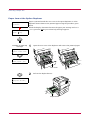
Setting the Paper Size in MP Tray
When using the MP tray in the cassette mode, you should set the same
paper size to the MP tray as that is used to format the job to print. The
factory default setting is A4 or Letter.
This menu does not appears when the option envelope feeder is installed on
the printer.
For more details about the paper sizes that can be fed from the MP tray, see
Chapter 2.
1
2
Press the MENU key.
Press the
or
key repeatedly until Paper Handling > appears.
Paper Handling >
1-28
Paper Handling
3
4
Press the > key.
Press the
or
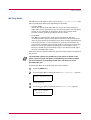
key repeatedly until >MP Tray Size appears.
>MP Tray Size
A4
5
Press the ENTER key. A blinking question mark (?) appears.
>MP Tray Size
? A4
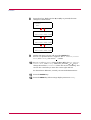
6
Press the or key to display the desired MP tray size. The display
changes as shown below.
A4
Executive
Letter
Legal
Custom
Hagaki
OufukuHagaki
Oficio II
Statement
Folio
Youkei 2
Youkei 4
16K
Monarch
Business
Comm. #9
Comm. #6 3/4
DL
C5
A6
B6
A5
B5
ISO B5
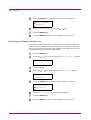
7
8
When the desired paper size is displayed, press the ENTER key.
Press the MENU key. The message display returns to Ready.
The paper size setting for the MP tray is completed.
1-29
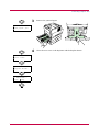
Paper Handling
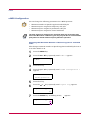
Setting the Paper Type
Set the paper types according to the paper to be set in the cassette and the
MP tray.
Setting the Paper Type in Paper Cassette
Make this setting to match the paper type fed from the paper cassette of
the printer. If the paper type is set correctly, you can perform printing
using the media type selection function from the application software
(printer driver). The factory default setting is Plain.
For more details about the paper types that can be fed from the paper
cassette, see Chapter 2.
1
2
Press the MENU key.
Press the
or
key repeatedly until Paper Handling > appears.
Paper Handling >
3
4
Press the > key.
Press the
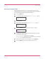
or
key repeatedly until >Cassette Type appears.
>Cassette Type
Plain
5
Press the ENTER key. A blinking question mark (?) appears.
>Cassette Type
? Plain
6
Press the or key to display the desired cassette type. The display
changes as shown below.
Plain
Preprinted
Bond
Recycled
Rough
Letterhead
Color
Prepunched
High quality
Custom(1 to 8)
7
8
When the desired cassette type is displayed, press the ENTER key.
Press the MENU key. The message display returns to Ready.
1-30
Paper Handling
Setting the Paper Type in MP Tray
You can automatically select the paper cassette according to the selection
made by the application software (printer driver). The factory default
setting is Plain.
This menu does not appears when the option envelope feeder is installed on
the printer.
For more details about the paper types that can be fed from the MP tray,
see Chapter 2.
1
2
Press the MENU key.
Press the
or
key repeatedly until Paper Handling > appears.
Paper Handling >
3
4
Press the > key.
Press the
or
key repeatedly until >MP Tray Type appears.
>MP Tray Type
Plain
5
Press the ENTER key. A blinking question mark (?) appears.
>MP Tray Type
? Plain
1-31
Paper Handling
6
Press the or key to display the desired MP tray type. The display
changes as shown below.
Plain
Transparency
Preprinted
Labels
Bond
Recycled
Vellum
Rough
Letterhead
Color
Prepunched
Envelope
Cardstock
Thick
High quality
Custom (1 to 8)
7
8
When the desired MP tray type is displayed, press the ENTER key.
Press the MENU key and the message display returns to Ready.
Creating Custom Paper Type
The following describes the procedure used to set a user-defined paper type
for the printer. Eight custom user settings may be registered. After having
been set, any of these may be called up when setting the paper type for a
paper source.
The paper weight and duplex path can be set (see Setting the Paper
Weight on page 1-34, and Setting the Duplex Path on page 1-35) after
selecting the paper type to be customized as follows. For how to reset the
customized settings, see Resetting the Custom Paper Type on page 1-36.
1
2
Press the MENU key.
Press the
or
key repeatedly until Paper Handling > appears.
Paper Handling >
3
4
Press the > key.
Press the
or
key repeatedly until >Type Adjust > appears.
>Type Adjust
Custom 1
1-32
>
Paper Handling
5
Press the ENTER key. A blinking question mark (?) appears.
>Type Adjust
? Custom 1
6
>
Press the or key to display the desired paper type. The display
changes as shown below.
Custom (1 to 8)
Plain
Transparency
Preprinted
Labels
Bond
Recycled
Vellum
Rough
Letterhead
Color
Prepunched
Envelope
Cardstock
Thick
High quality
7
When the paper type to be customized is displayed, press the ENTER
key.
8
Press the > key and proceed to Setting the Paper Weight on the
following page.
Proceed to Setting the Paper Weight and Setting the Duplex Path
starting from the following page.
1-33
Paper Handling
Setting the Paper Weight
You can set the paper thickness for your custom paper type to be
customized.
1
Display the custom paper type (see Creating Custom Paper Type
on page 1-32) and press the > key.
2
Press the
or
key repeatedly until >>Paper Weight appears.
>>Paper Weight
Normal 2
3
Press the ENTER key. A blinking question mark (?) appears.
>>Paper Weight
? Normal 2
4
Press the or key to display the desired paper thickness. The
display changes as shown below. For details of the default setting for
each paper type, see Paper Type on page 2-12.
Light
Normal 1
Normal 2
Normal 3
Heavy l
Heavy 2
Heavy 3
Extra Heavy
5
6
When the desired paper thickness displayed, press the ENTER key.
Press the MENU key. The message display returns to Ready.
If the paper type is set to Custom and the option duplexer is installed
on the printer, duplex printing can be enabled and disabled. See
Setting the Duplex Path on the following page.
1-34
Paper Handling
Setting the Duplex Path
To use this function, the duplexer must be installed on the printer.
Option
If the paper type is set to Custom and the option duplexer is installed on
the printer, you can set whether or not to enable duplex printing as follows.
The default setting is Enable.
1
Display the custom paper type (see Creating Custom Paper Type
on page 1-32) and press the > key.
2
Press the
or
key repeatedly until >>Duplex Path appears.
>>Duplex Path
Enable
3
Press the ENTER key. A blinking question mark (?) appears.
>>Duplex Path
? Enable
4
Select Enable or Disable using the or key. For details of the
default setting for each paper type, see Paper Type on page 2-12.
5
6
Press the ENTER key.
Press the MENU key. The message display returns to Ready.
The custom paper type setting is completed.
1-35
Paper Handling
Resetting the Custom Paper Type
Resets the settings of Custom 1 to 8 that are set in Creating Custom
Paper Type on page 1-32.
1
2
Press the MENU key.
Press the
or
key repeatedly until Paper handling > appears.
Paper Handling >
3
4
Press the > key.
Press the
appears.
or
key repeatedly until >Reset Type Adjust
>Reset Type
Adjust
5
Press the ENTER key. A question mark (?) appears.
>Reset Type
Adjust ?
6
Press the ENTER key. All the customized paper weight and duplex
path settings will be reset to the default. The message display
returns to Ready.
1-36
Paper Handling
MP Tray Mode
The MP tray can be used in either of two modes – first or cassette. The
MP tray feed paper differently depending on the mode:
•
Cassette Mode
This is the default mode. The MP tray acts in the same manner as
other paper source. The printer can correctly feed paper from any paper
source as you command on the printer driver. The cassette mode
provides a faster printing speed than the first mode.
•
First Mode
The MP tray automatically feeds paper placed on the MP tray
overriding another paper source that is selected on the printer driver.
After all paper sheets in the MP tray have been used up (approximately
100 sheets [A4 size, 0.11 mm thickness]), paper will be fed from the
paper source originally selected. This mode is convenient to feed paper
of special size or type without reloading the current paper source.
However, the MP tray must be kept empty if you desire to feed paper
from the intended paper source.
This menu does not appears when the option envelope feeder is installed on
the printer.
Note
The maximum capacity for the MP tray of 100 sheets is based on A4
paper. If you use Legal size paper on the MP tray, the number of paper
you use should be considerably smaller than 100 sheets to avoid
possible paper jam.
To switch the MP tray to First mode, proceed as follows:
1
2
Press the MENU key.
Press the
or
key repeatedly until Paper Handling > appears.
Paper Handling >
3
4
Press the > key.
Press the
or
key repeatedly until >MP Tray Mode appears.
>MP Tray Mode
Cassette
1-37
Paper Handling
5
Press the ENTER key. A blinking question mark (?) appears.
>MP Tray Mode
? Cassette
6
7
8
Select First or Cassette using the
or
key.
Press the ENTER key.
Press the MENU key. The message display returns to Ready.
Selecting the Paper Feed Source
You can select from which paper source printing will be performed. If no
option units are installed, the only selections are the paper cassette and
MP tray of the printer. If option paper feeders are installed, they can also
be selected using the manner described below.
1
2
Press the MENU key.
Press the
or
key repeatedly until Paper Handling > appears.
Paper Handling >
3
4
Press the > key.
Press the
or
key repeatedly until >Feed Select appears.
>Feed Select
Cassette
5
Press the ENTER key. A blinking question mark (?) appears.
>Feed Select
? Cassette
6
7
8
Select MP tray or Cassette using the
or
key.
Press the ENTER key.
Press the MENU key. The message display returns to Ready.
1-38
Paper Handling
Selecting the Output Stack
The following procedure allows you to select whether printouts will be
received by the top tray or to the rear tray. If an option sorter is installed, it
can also be selected using the manner described below.
1
2
Press the MENU key.
Press the
or
key repeatedly until Paper Handling > appears.
Paper Handling >
3
4
Press the > key.
Press the
or
key repeatedly until >Stack Select appears.
>Stack Select
Top tray FaceDn
5
Press the ENTER key. A blinking question mark (?) appears.
>Stack Select
?Top tray FaceDn
6
Press the or key to display the desired destination. The output
tray changes as shown below.
Top tray FaceDn (Printer’s top tray) [Default]
RearTray FaceUp (Printer’s rear tray) [Option rear tray required]
Sorter FaceDn [Option sorter required]
7
8
When the desired paper source displayed, press the ENTER key.
Press the MENU key. The message display returns to Ready.
1-39
Paper Handling
Overriding A4 and Letter Size Difference
This selects whether to enable or disable the difference between A4 size
and Letter size. Under the default setting of Off, the paper size of the
paper source is matched to the paper size formatting the jobs. If these
differ, a corresponding error message is displayed. When this is set to On,
printing is performed even if the actual paper size differs from the paper
size formatting the jobs.
1
2
Press the MENU key.
Press the
or
key repeatedly until Paper Handling > appears.
Paper Handling >
3
4
Press the > key.
Press the
or
key repeatedly until >Override A4/LT appears.
>Override A4/LT
Off
5
Press the ENTER key. A blinking question mark (?) appears.
>Override A4/LT
? Off
6
7
8
Select On or Off using the
or
key.
Press the ENTER key.
Press the MENU key. The message display returns to Ready.
1-40
Pagination
Pagination
The items regarding pagination can be made from the operator panel. The
items that can be set are shown below.
•
Emulation
•
Font
•
Code Set
•
Number of Copies
•
Printing Orientation
•
KIR (Kyocera Image Refinement)
•
Ecoprint
•
Resolution
Emulation
The following procedure allows you to select the printer’s emulation mode.
Changing the Emulation
To change the emulation mode, proceed as follows:
1
2
Press the MENU key.
Press the or key repeatedly until Emulation appears. One of
the emulation modes shown below appears, indicating the current
emulation.
PCL 6 (default)
KPDL
KPDL (AUTO)
Line Printer
IBM Proprinter
DIABLO 630
EPSON LQ-850
KPDL is the Kyocera’s implementation of the PostScript page
description language.
3
Press the ENTER key. A blinking question mark (?) appears.
Emulation
?PCL 6
4
Press the
appears.
or
key repeatedly until the desired emulation mode
1-41
Pagination
5
6
Press the ENTER key.
Press the MENU key. The message display returns to Ready.
Alternative Emulation for KPDL Emulation
The auto KPDL (KPDL (AUTO)) emulation enables the printer to
automatically change the emulation mode according to the print job
received. The alternative emulation can be selected using the operator
panel. The default alternative emulation is PCL 6.
1
2
Press the MENU key.
Press the
or
key repeatedly until Emulation appears.
Emulation
PCL 6
3
Press the ENTER key. A blinking question mark (?) appears.
Emulation
?PCL 6
4
Press the or key repeatedly until the message display indicated
KPDL (AUTO) appears.
Emulation
?KPDL (AUTO)
5
6
Press the ENTER key.
Press the > key. When > Print KPDL Errs is displayed, press the
or key. The display cycles through the emulation in the following
order:
PCL 6 (default)
Line Printer
IBM Proprinter
DIABLO 630
EPSON LQ-850
7
Press the ENTER key. A blinking question mark (?) appears.
>Alt. Emulation
?PCL 6
1-42
Pagination
8
Press the or key repeatedly until the desired alternative
emulation appears.
9 Press the ENTER key.
10 Press the MENU key. The message display returns to Ready.
Printing KPDL Errors
The printer can print error descriptions when printing error occurs during
KPDL emulation. The default is Off – the printer does not print KPDL
errors.
1
2
Press the MENU key.
Press the
or
key repeatedly until Emulation > appears.
Emulation
PCL 6
3
Press the ENTER key. A blinking question mark (?) appears.
Emulation
?PCL 6
4
Select KPDL or KPDL (AUTO) using the
or
key.
Emulation
?KPDL
5
6
Press the ENTER key.
Press the > key. The message display changes to that shown below. If
>Alt. Emulation is displayed when the KPDL (AUTO) emulation
is selected, press the or key to change it.
>Print KPDL Errs
Off
7
Press the ENTER key. A blinking question mark (?) appears.
>Print KPDL Errs
? Off
1-43
Pagination
8
Select On using the
or
key.
>Print KPDL Errs
? On
9 Press the ENTER key.
10 Press the MENU key. The message display returns to Ready.
Font
You can select the default font for the current interface. In addition to the
internal fonts, all fonts that are downloaded to the printer memory, or fonts
stored on a CompactFlash card, Microdrive, or option ROM, can be selected
as the default font.
In this menu, you can also set the type and pitch for Courier and Letter
Gothic.
Default font
1
2
Press the MENU key.
Press the
or
key repeatedly until Font > appears.
Font
3
4
>
Press the > key.
Press the
or
key repeatedly until >Font Select > appears.
>Font Select
Internal
5
>
To select an internal font, check that Internal is displayed. If
Internal is not displayed, press the ENTER key. Press the or
key repeatedly until the message display indicates Internal and
press the ENTER key.
To select an option font, press the ENTER key. Press the or key
repeatedly until the message display indicates Option and press the
ENTER key. This operation is possible only when option fonts are
installed in the printer.
1-44
Pagination
6
Press the > key. The message display changes to that show below.
>> I000
The letter before the number indicates the type of font as shown
below:
Letter
Description
I
Internal font
S
Soft (down load) font
M
Fonts in an option CompactFlash card
H
Fonts in a RAM disk or option Microdrive.
O
Fonts in an option ROM
Table 1-6
7
Press the ENTER key. A blinking question mark (?) appears.
>>?I000
8
Press the or key repeatedly until the desired font number
appears. For font numbers of the internal fonts, see List of Fonts on
page 5-2.
9 When the desired font is displayed, press the ENTER key.
10 Press the MENU key. The message display returns to Ready.
1-45
Pagination
Default Font Size
The following procedure determines the size of the default font. If the
default font is a fixed font such as Courier or Letter Gothic, the character
pitch can be changed instead of the font size.
1
2
Press the MENU key.
Press the
or
key repeatedly until Font > appears.
Font
3
4
>
Press the > key.
Press the
or
key repeatedly until >Font Select > appears.
>Font Select
Internal
5
6
>
Check that Internal is displayed and press the > key.
Press the
or
key repeatedly until >>Size appears.
>>Size
012.00 point(s)
7
Press the ENTER key. A blinking cursor ( _ ) appears.
>>Size
012.00 point(s)
8
Press the or key to increase or decrease the value of the figure
where the cursor is blinking. The font size can be set between 4 and
999.75 points, in 0.25-point increments. You can use the > or < key to
move the cursor right and left.
9 When the desired size is displayed, press the ENTER key.
10 Press the MENU key. The message display returns to Ready.
1-46
Pagination
Changing Type for Courier/Letter Gothic
Courier or Letter Gothic font type can be selected as Regular or Dark. For
example, to change the type of Courier, proceed as follows:
1
2
Press the MENU key.
Press the
or
key repeatedly until Font > appears.
Font
3
4
>
Press the > key.
Press the
or
key repeatedly until >Font Select > appears.
>Font Select
Internal
5
6
>
Check that Internal is displayed and press the > key.
Press the
or
key repeatedly until >>Courier appears.
>>Courier
Regular
7
Press the ENTER key. A blinking question mark (?) appears.
>>Courier
? Regular
8 Select Regular or Dark using the or key.
9 Press the ENTER key.
10 Press the MENU key and the message display returns to Ready.
1-47
Pagination
Setting the Character Pitch for Courier/Letter Gothic
The character pitch for fixed fonts is adjustable when the default font is
Courier or Letter Gothic.
1
2
Press the MENU key.
Press the
or
key repeatedly until Font > appears.
Font
3
4
>
Press the > key.
Press the
or
key repeatedly until >Font Select > appears.
>Font Select
Internal
5
6
>
Check that Internal is displayed and press the > key.
Press the
or
key repeatedly until >>Pitch appears.
>>Pitch
10.00 cpi
7
Press the ENTER key. A blinking cursor ( _ ) appears.
>>Pitch
10.00 cpi
8
Press the or key to increase or decrease the value of the figure
where the cursor is blinking. The character pitch can be set between
0.44 and 99.99 characters per inch, in 0.01 character-per-inch
increments. You can use the > or < keys to move the cursor right and
left.
9 When the desired size is displayed, press the ENTER key.
10 Press the MENU key. The message display returns to Ready.
1-48
Pagination
Code Set
You can change the character code set. Available character code sets vary
depending on the current font. (The default is IBM PC-8.)
1
2
Press the MENU key.
Press the
or
key repeatedly until Font > appears.
Font
3
>
Press the > key. Press the
or
key until > Code Set appears.
>Code Set
IBM PC-8
4
Press the ENTER key. A blinking question mark (?) appears.
>Code Set
?IBM PC-8
5
6
7
Press the
or
key until the desired character code set appears.
Press the ENTER key.
Press the MENU key. The message display returns to Ready.
1-49
Pagination
Number of Copies
You can set the number of copies to be printed of each page for the current
interface. The number of copies can be set between 1 and 999.
1
2
Press the MENU key.
Press the
or
key repeatedly until Page set > appears.
Page Set
3
4
>
Press the > key.
Press the
or
key repeatedly until >Copies appears.
>Copies
001
5
Press the ENTER key. A blinking cursor ( _ ) appears.
>Copies
001
6
Press the or key to increase or decrease the value of the figure
where the cursor is blinking. It can be set between 1 and 999. You
can use the > and < keys to move the right and left.
7
8
When the desired size is displayed, press the ENTER key.
Press the MENU key. The message display returns to Ready.
1-50
Pagination
Printing Orientation
The default orientation of the page can be selected from the portrait
(upright) and landscape (sideways) page orientation.
Portrait orientation
Landscape orientation
A
1
2
A
Press the MENU key.
Press the
or
key repeatedly until Page Set > appears.
Page Set
3
4
>
Press the > key.
Press the
or
key repeatedly until >Orientation appears.
>Orientation
Portrait
5
Press the ENTER key. A blinking question mark (?) appears.
>Orientation
? Portrait
6
7
8
Select Portrait or Landscape using the
or
key.
Press the ENTER key.
Press the MENU key. The message display returns to Ready.
1-51
Pagination
KIR (Kyocera Image Refinement)
This printer incorporates the KIR (Kyocera Image Refinement) smoothing
function. This function provides high print quality by providing software
enhancement of print resolution.
Q
With KIR Off
With KIR On (default)
Set the print density to 3 when setting the KIR mode. For details on print
density, see page 1-95.
Note
Look at the check line, the last line on a status page, to make the optimum
KIR mode setting.
Status Page
Optimized stripes
FS-3830N Page Printer
STATUS PAGE
Firmware Version:
Hardware Information
Page Information
Network Status
Released:
The current KIR setting is optimal.
Memory
Installed Options
Emulation
Error Log
Toner Gauge
100
0
Dark vertical stripes
Interfaces
KIR Checking
Lines
KIR Test pattern
Set the KIR mode to Off. Try printing the status
page again. If you still get dark vertical stripes,
adjust the print density control to a lighter setting.
ON
White vertical stripes
Set the KIR mode to On. Try printing the status
page again. If you still get white vertical stripes,
adjust the print density control to a darker setting.
1-52
Pagination
1
2
Press the MENU key.
Press the
or
key repeatedly until Print Quality > appears.
Print Quality >
3
4
Press the > key.
Press the
or
key repeatedly until >KIR Mode appears.
>KIR Mode
On
5
Press the ENTER key. A blinking question mark (?) appears.
>KIR Mode
? On
6
7
8
Select On or Off using the
or
key.
Press the ENTER key.
Press the MENU key. The message display returns to Ready.
1-53
Pagination
Ecoprint
The Ecoprint enables you to reduce the amount of toner consumed on the
page so as to save your printing costs. You can set to Ecoprint mode on, as
follows. (The factory default setting is Off.)
The Ecoprint setting has no effect on the print speed.
The Ecoprint mode setting is On when the printing image becomes lighter,
yet very readable.
Ecoprint setting is Off
(default).
1
2
Ecoprint setting is On
Press the MENU key.
Press the
or
key repeatedly until Print Quality > appears.
Print Quality >
3
4
Press the > key.
Press the
or
key repeatedly until >EcoPrint Mode appears.
>EcoPrint Mode
Off
5
Press the ENTER key. A blinking question mark (?) appears.
>EcoPrint Mode
? Off
6
7
8
Select On or Off using the
or
key.
Press the ENTER key.
Press the MENU key. The message display returns to Ready.
1-54
Pagination
Resolution
Proceed as follows to set the default print resolution from four ways — 300
dpi, 600 dpi, Fast 1200 mode, and Fine 1200 mode. The clarity of
printed characters and graphics becomes sharper in this order.
1
2
Press the MENU key.
Press the
or
key repeatedly until Print Quality > appears.
Print Quality >
3
4
Press the > key.
Press the
or
key repeatedly until >Resolution appears.
>Resolution
Fast 1200 mode
5
Press the ENTER key. A blinking question mark (?) appears.
>Resolution
? Fast 1200 mode
6
Select Fast 1200 mode, Fine 1200 mode, 300 dpi or 600 dpi
using the or key.
7
8
Press the ENTER key.
Press the MENU key. The message display returns to Ready.
1-55
e-MPS
e-MPS
e-MPS is an abbreviation for ‘enhanced-Multiple Printing System’ which
implements the following functions that are available from the printer
driver:
•
Job Retention
•
Job Storage
In either job mode, when printing a document, the print data is transferred
from the computer to the printer then stored on the printer’s hard disk.
Since copies of the document are printed using the stored data, printing is
performed faster with less computer spooling time and less network traffic.
Note
•
To use the e-MPS system, an option hard disk must be installed in the
printer. For details, see Appendix A Options.
•
The RAM disk may also be used in the Proof-and-Hold and Private
Print modes. See Activating the RAM Disk on page 1-81 for details on
RAM disk setup.
Job Retention
Job Retention has four modes as summarized below. These modes are
selected when you choose on the printer driver through the application
software:
Mode
Quick Copy
Proof and Hold
Private Print
Stored Job
Primary function
To later print
additional copies
To proof the first copy
before printing
multiple copies
To hold the document
in printer to prevent
unauthorized access
To electronically
store documents such
as fax cover pages
Start storing by
Printer driver
Printer driver
Printer driver
Printer driver
On terminating print
setting from
application software
Prints
simultaneously
Prints one copy
simultaneously
Does not print
Does not print
Retrieved by
Operator panel
Operator panel
Operator panel
Operator panel
Default number of
copies printed at
retrieval
Same as storing
(can be changed)
One less
(can be changed)
Same as storing
(can be changed)
One
(can be changed)
Maximum number of
jobs stored†
32, expandable to 50
32, expandable to 50
Depends on the hard
disk capacity
(Private jobs are
deleted automatically
once it is retrieved.)
Depends on the hard
disk capacity
PIN security
No
No
Yes
Yes (if necessary)
Data after printing
Stored
Stored
Deleted
Stored
Data at power off
Deleted
Deleted
Deleted
Stored
Hard disk required
Yes
No
No
Yes
Table 1-7
†
Jobs in excess will cause the earlier ones to be deleted.
1-56
e-MPS
Job Storage
Job storage stores print jobs either temporarily or permanently, or in
virtual mailboxes, as you click an appropriate radio button on the printer
driver when printing from a computer.
Virtual Mailbox
Virtual mailbox is part of Job Storage, which stores print jobs on the
Virtual mailbox is part of Job Storage, which stores print jobs on the hard
disk without printing. It enables you to retrieve jobs later from the
operator panel or the KM-NET Printer Disk Manager utility in the CDROM.
Each mailbox may be used by an individual who desires to share the
printer in this mode. By default, each mailbox is numbered from ‘Tray 001,’
‘Tray 002,’ ... etc. To ‘post’ a job in one of these mailboxes, you assign a
numbered or named mailbox on the printer driver when printing.
To retrieve the stored job for printing, see Retrieving Jobs from Virtual
Mailbox (VMB) on page 1-68.
The virtual mailbox can be used in PCL 6 emulation only.
Quick Copy
Note
This mode enables you to print the requested number of copies of a job,
simultaneously storing the job on the Microdrive. When additional copies
are required, you can reprint the required number of copies from the
printer operator panel. To print a job as a quick copy job, see KX Printer
Drivers Operation Guide.
The default number of print jobs that can be stored on the Microdrive is 32.
This value can be increased to up to 50 from the e-MPS Configuration
menu. For details, see e-MPS Configuration on page 1-70. When the
number of jobs reaches the limit, the oldest job will be overwritten by the
new one.
When the printer is turned off, all stored jobs will be deleted.
Printing Additional Copies using Quick Copy
To print additional copies of a job stored in the printer:
1
2
Press the MENU key.
Press the
or
key repeatedly until e-MPS > appears.
e-MPS
>
1-57
e-MPS
3
4
Press the > key.
Press the or key repeatedly until >Quick Copy appears
followed by the user name (Harold, in this example). The user name
is assigned at printing using the printer driver.
>Quick Copy
Harold
5
Press the ENTER key. A blinking question mark (?) appears before
the user name.
>Quick Copy
?Harold
6
Press the
example.
or
key to display the desired user name, Arlen, in this
>Quick Copy
?Arlen
7
Press the ENTER key. The job name entered in the printer driver
(Report, in this example) appear with a blinking question mark (?)
before the letters.
>Arlen
?Report
8
9
Press the
or
key to scroll to the desired job title.
Press the ENTER key. The number of copies to be printed can be set.
To increase the copy count, press the key; to decrease the copy
count, press the key.
>Report
Copies
001
the ENTER key to finalize the copy count. The printer prints
10 Press
the specified number of copies for the job.
1-58
e-MPS
Deleting a Quick Copy Job
All quick copy jobs are automatically deleted when the printer is turned off.
If you desire to explicitly delete a stored quick copy job, proceed as follows:
1
Follow steps 1 through 8 in the above section to let the title of the job
displayed.
2
When the title of the job is displayed, e.g. Report, below, press the
ENTER key. The cursor below the copy count starts to blink.
>Report
Copies
3
Press the
001
key repeatedly until Delete appears below the title.
>Report
Delete
4
_
Press the ENTER key. The stored quick copy job is deleted.
Proof and Hold
When you print multiple copies, this mode first prints one copy so that you
can proof it before continuing to print the remaining copies. Since you can
proof the printouts before printing the remaining copies, wastage of paper
can be reduced.
The printer prints one copy and, at the same time, saves the print job on
the Microdrive. You can also change the number of copies when resuming
printing from the operator panel.
When the printer is turned off, all stored jobs will be deleted.
Printing Remaining Copies of a Proof and Hold Job
Printing a Proof and Hold job on the operator panel is similar to printing a
quick copy job. To print remaining copies of a job held in the printer:
1
2
Press the MENU key.
Press the
or
key repeatedly until e-MPS > appears.
e-MPS
3
>
Press the > key.
1-59
e-MPS
4
Press the or key repeatedly until >Quick Copy appears
followed by the user name (Harold, in this example). The user name
is assigned at printing using the printer driver.
>Quick Copy
Harold
5
Press the ENTER key. A blinking question mark (?) appears before
the user name.
>Quick Copy
?Harold
6
Press the
example.
or
key to display the desired user name, Arlen, in this
>Quick Copy
?Arlen
7
Press the ENTER key. The job name entered in the printer driver
(Report, in this example) appear with a blinking question mark (?)
before the letters.
>Arlen
?Report
8
9
Press the
or
key to scroll to the desired job title.
Press the ENTER key. The number of copies to be printed can be set.
To increase the copy count, press the key; to decrease the copy
count, press the key.
>Report
Copies
001
the ENTER key to finalize the copy count. The printer prints
10 Press
the specified number of copies for the job.
1-60
e-MPS
Printing a Private Job
In private printing, you can specify that a job is not printed until you
release the job from the operator panel. At sending the job from the
application software, you should specify a 4-digit access code in the printer
driver. The job is released for printing by entering the access code on the
operator panel. Thus, this function ensures confidentiality of the print job.
When the printer is turned off, all the print jobs will be deleted.
Releasing a Private Job
To print a private job through the operator panel:
1
2
Press the MENU key.
Press the
or
key repeatedly until e-MPS > appears.
e-MPS
3
4
>
Press the > key.
Press the or key repeatedly until >Private/Stored appears.
The name entered in the printer driver (Harold, in this example)
also appears.
>Private/Stored
Harold
5
Press the ENTER key. A blinking question mark (?) before a user
name appears.
>Private/Stored
?Harold
6
Press the
example).
or
key to display the desired user name (Arlen, in this
>Private/Stored
?Arlen
7
Press the ENTER key. The user name and the job name (Agenda, in
this example) entered in the printer driver appear with a blinking
question mark (?).
>Arlen
?Agenda
1-61
e-MPS
8
9
Press the
or
key to display the desired job title.
Press the ENTER key. The ID input line appears. Enter the four-digit
access code entered in the printer driver and press the ENTER key.
To enter the ID, press the < or > key to move the cursor to the
number to be changed and then enter the correct number by pressing
the or key.
>Agenda
ID
0000
can set the number of copies to be printed. To increase the copy
10 You
count, press the key; to decrease the copy count, press the key.
>Agenda
Copies
11
001
Press the ENTER key to finalize the copy count. The printer prints
the specified number of copies for the job.
Deleting a Private Job
To delete a stored private job, proceed as follows:
1
2
Follow steps 1 through 8 in the above section.
When the title of the job to be printed is displayed (Agenda, in this
example), press the ENTER key. Enter the four-digit access code
entered in the printer driver and press the ENTER key.
>Agenda
Copies
3
Press the
copies.
001
key repeatedly until Delete appears for the number of
>Agenda
Delete
4
_
Press the ENTER key. The private job is deleted from the Microdrive.
1-62
e-MPS
Printing a Stored Job
The procedure below allows you to store print jobs to the Microdrive that
are frequently needed such as fax cover pages, check lists, and order forms,
for printing at any later time using the operator panel.
The print jobs will not be deleted when the printer is turned off.
Releasing a Stored Job
To print a stored job through the operator panel:
1
2
Press the MENU key.
Press the
or
key repeatedly until e-MPS > appears.
e-MPS
3
4
>
Press the > key.
Press the or key repeatedly until >Private/Stored appears.
The name entered in the printer driver (Harold, in this example)
also appears.
>Private/Stored
Harold
5
Press the ENTER key. A blinking question mark (?) before a user
name appears.
>Private/Stored
?Harold
6
Press the
example).
or
key to display the desired user name (Arlen, in this
>Private/Stored
?Arlen
7
Press the ENTER key. The user name and the job name (Agenda, in
this example) entered in the printer driver appear with a blinking
question mark (?).
>Arlen
?Agenda
1-63
e-MPS
8
9
Press the
or
key to display the desired job title.
Press the ENTER key. If you entered an access code for the printer
driver, the ID input line appears. Enter the four-digit access code
entered in the printer driver and press the ENTER key. To enter the
ID, press the < or > key to move the cursor to the number to be
changed and then enter the correct number by pressing the or
key.
>Agenda
ID
0000
can specify the number of copies to print. To increase the copy
10 You
count, press the key; to decrease the key.
>Agenda
Copies
11
001
Press the ENTER key to finalize the copy count. The printer prints
the specified number of copies for the job.
Deleting a Stored Job
To delete a stored job, proceed as follows:
1
2
Follow steps 1 through 8 in the above section.
When the title of the job to be printed is displayed (Agenda, in this
example), press the ENTER key. If you entered an access code for the
printer driver, enter the four-digit access code and press the ENTER
key.
>Agenda
Copies
3
Press the
copies.
001
key repeatedly until Delete appears for the number of
>Agenda
Delete
4
_
Press the ENTER key. The stored job is deleted from the Microdrive.
1-64
e-MPS
Printing a Code Job
KM-NET Job Manager
Install the KM-NET for Clients software from the CD-ROM supplied with
the printer. To do this, from the CD-ROM Main Menu, select Printer
Utilities > KM-NET for Clients.
1
Browse through Windows Start > Programs > Kyocera Mita > KMNET for Clients.
2
Click the Add Printer icon (below). Select the Local or Network port.
Add Printer Icon
3
Follow the wizard until the Discovered Printing System(s) dialog
box is reached. When the printer is found in the list, click (highlight)
it, then Finish.
1-65
e-MPS
4
Select the printer and then click on the Job Manager icon. The jobs
that are stored in that printer will be displayed. To print the job,
right click Job name and then click Print on the drop down list that
appears.
Job Manager Icon
For more detailed information, refer to KM-NET for Clients Operation
Guide that is included on the CD-ROM which comes with the printer.
1-66
e-MPS
Printing a List of Code Jobs
If you select Permanent Job Storage on the printer driver, you can have a
List of Code Job printed using the operator panel.
1
2
Press the MENU key.
Press the
or
key repeatedly until e-MPS > appears.
e-MPS
3
4
>
Press the > key.
Press the
or
key repeatedly until >List of Code JOB appears.
>List of
Code JOB
5
Press the ENTER key. A question mark (?) appears.
>List of
Code JOB ?
6
Press the ENTER key again. The printer prints a Code Job list.
1-67
e-MPS
Retrieving Jobs from Virtual Mailbox (VMB)
To use this mode, an option Microdrive must be installed in the printer.
Option
To retrieve the jobs posted in the virtual mailbox, proceed as follows.
1
2
Press the MENU key.
Press the
or
key repeatedly until e-MPS > appears.
e-MPS
3
4
>
Press the > key.
Press the or key repeatedly until >Print VMB Data appears.
The virtual mailbox number will also appear.
>Print VMB Data
Tray001:
5
Press the ENTER key. A blinking question mark (?) appears.
>Print VMB Data
Tray001?
6
Press the ENTER key. The document in the mailbox is printed and
automatically deleted from the mailbox.
1-68
e-MPS
Printing a List of VMB
A Virtual Mailbox list includes the jobs currently stored in the mailboxes.
1
2
Press the MENU key.
Press the
or
key repeatedly until e-MPS > appears.
e-MPS
3
4
>
Press the > key.
Press the
or
key repeatedly until >List of VMB appears.
>List of VMB
5
Press the ENTER key. A question mark (?) appears.
>List of VMB ?
6
Press the ENTER key again. The printer prints a list of jobs currently
posted in the virtual mailboxes.
1-69
e-MPS
e-MPS Configuration
You can change the following parameters for e-MPS operation:
Option
Note
•
Maximum number of Quick Copy/Proof and Hold jobs
•
Maximum space assigned to temporary code jobs
•
Maximum space assigned to permanent code jobs
•
Maximum space assigned to virtual mailboxes
The total amount of storage areas specified must not exceed the total
size of the Microdrive. Otherwise, you may only be able to accommodate
print jobs of a smaller amount of print jobs than specified.
Changing the Maximum Number of Quick Copy/Proof and Hold
Jobs
This changes maximum number of Quick Copy/Proof and Hold jobs from 0
to 50. The default is 32.
1
2
Press the MENU key.
Press the
or
key repeatedly until e-MPS > appears.
e-MPS
3
4
>
Press the > key.
Press the
appears.
or
key repeatedly until >e-MPS Configuration >
>e-MPS
>
Configuration
5
6
Press the > key.
Press the
or
key repeatedly until >>Quick Copy appears.
>>Quick Copy
32
7
Press the ENTER key. A blinking cursor (
>>Quick Copy
32
1-70
) appears.
e-MPS
8
Press the or key to increase or decrease the value at the blinking
cursor. The value can be set between 0 and 50. Use the > and < keys
to move the cursor right and left.
9
When the desired maximum number of jobs is set, press the ENTER
key.
10 Press the MENU key. The message display returns to Ready.
Maximum Space Assigned to Temporary Code Jobs
This changes the Microdrive space that holds temporary code jobs. You can
change the maximum space from 0 to 9999 (megabytes). The actual
maximum size depends on the size of free hard disk space, however. The
default size is 50 MB.
1
2
Press the MENU key.
Press the
or
key repeatedly until e-MPS > appears.
e-MPS
3
4
>
Press the > key.
Press the
appears.
or
key repeatedly until >e-MPS Configuration >
>e-MPS
>
Configuration
5
6
Press the > key.
Press the
appears.
or
key repeatedly until >>Temp. Code JOB Size
>>Temp. Code JOB
Size
050MB
7
To change the maximum disk space, press the ENTER key. A
blinking cursor ( ) appears.
>>Temp. Code JOB
Size
050MB
1-71
e-MPS
8
Press the or key to increase or decrease, respectively, the value
at the blinking cursor. Use the > and < keys to move the cursor right
and left.
9 When the desired size is displayed, press the ENTER key.
10 Press the MENU key. The message display returns to Ready.
Maximum Space Assigned to Permanent Code Jobs
This changes the Microdrive space that holds permanent code jobs. You can
change the maximum space from 0 to 9999 (megabytes). The actual
maximum size depends on the size of free Microdrive space, however. The
default size is 50 MB.
1
2
Press the MENU key.
Press the
or
key repeatedly until e-MPS > appears.
e-MPS
3
4
>
Press the > key.
Press the
appears.
or
key repeatedly until >e-MPS Configuration >
>e-MPS
>
Configuration
5
6
Press the > key.
Press the
appears.
or
key repeatedly until >>Perm. Code JOB Size
>>Perm. Code JOB
Size
050MB
7
Press the ENTER key. A blinking cursor (
) appears.
>>Perm. Code JOB
Size
050MB
8
Press the or key to increase or decrease, respectively, the value
at the blinking cursor. Use the > and < keys to move the cursor right
and left.
1-72
e-MPS
9 When the desired size is displayed, press the ENTER key.
10 Press the MENU key. The message display returns to Ready.
Maximum Space Assigned to Virtual Mailboxes
This changes the Microdrive space for virtual mailboxes. You can change
the maximum space from 0 to 9999 (megabytes). The actual maximum size
depends on the size of free Microdrive space, however. The default size is
50 MB.
1
2
Press the MENU key.
Press the
or
key repeatedly until e-MPS > appears.
e-MPS
3
4
>
Press the > key.
Press the
appears.
or
key repeatedly until >e-MPS Configuration >
>e-MPS
>
Configuration
5
6
Press the > key.
Press the
or
key repeatedly until >>VMB Size appears.
>>VMB Size
050MB
7
Press the ENTER key. A blinking cursor (
) appears.
>>VMB Size
050MB
8
Press the or key to increase or decrease, respectively, the value
at the blinking cursor. Use the > and < keys to move the cursor right
and left.
9 When the desired size is displayed, press the ENTER key.
10 Press the MENU key. The message display returns to Ready.
1-73
Interface
Interface
This printer is equipped with a parallel interface, a USB interface and a
network interface. An optional serial interface and a second network
interface can be installed as well. Various printing environment
parameters such as the default emulation can be changed indepently on
different interfaces by using the printer’s menu selection system. Before
select the interface to apply the changes in the procedure described below.
Note
This interface selection described below does not select which interface
data will be received from. The printer automatically selects an interface
data is received.
Parallel Interface Mode
The parallel interface mode of this printer supports a bi-directional/highspeed mode. Normally, this interface is used under the default setting
AUTO. For details, see Appendix B. After setting the interface, be sure to
reset the printer or turn the power off at least once. The new setting will be
enabled thereafter.
1
2
Press the MENU key.
Press the or key repeatedly until Interface > appears. One of
the interface names shown below appears, indicating the current
interface.
Parallel (default)
USB
Network
Serial (when a serial interface board kit is installed)
Option (when a network interface card is installed)
3
Press the ENTER key. A blinking question mark (?) appears.
Interface
? Parallel
If Parallel is not displayed, press the
is Parallel.
or
key repeatedly until it
If you want to abandon the interface selection procedure, press the
CANCEL key. The interface remains unchanged.
4
5
Press the ENTER key again.
Press the > key. The message display changes to the communication
mode menu.
1-74
Interface
6
Press the ENTER key. A blinking question mark (?) appears.
>Parallel I/F
? Auto
7
Press the or key to display the desired mode. The display
changes as shown below. Press the ENTER key.
Auto (default)
Normal
High Speed
Nibble (high)
8
Press the MENU key. The message display returns to Ready.
USB Interface Mode
About USB interface, for details, see Appendix C.
1
2
Press the MENU key.
Press the or key until Interface > appears. One of the
interface names shown below appears, indicating the current
interface.
Parallel (default)
USB
Network
Serial (when a serial interface board kit is installed)
Option (when a network interface card is installed)
3
Press the ENTER key. A blinking question mark (?) appears.
Interface
? Parallel
4
Press the
or
key until USB appears.
Interface
? USB
5
6
Press the ENTER key.
Press the MENU key. The message display returns to Ready.
1-75
Interface
Serial Interface Parameters
This section applies to the printers having the option serial interface
board kit (IB-11) installed.
Option
The baud rate, data bits, stop bits, parity, and protocol for the serial
interface can be set as follows:
1
2
Press the MENU key.
Press the or key repeatedly until Interface > appears. One of
the interface names shown below appears, indicating the current
interface.
Parallel (default)
USB
Network
Serial (when a serial interface board kit is installed)
Option (when a network interface card is installed)
3
Press the ENTER key. A blinking question mark (?) appears.
Interface
? Parallel
If you want to abandon the interface selection procedure, press the
CANCEL key. The interface remains unchanged.
4
Press the
or
key repeatedly until Serial appears.
Interface
? Serial
5
Press the ENTER key again.
1-76
Interface
6
Press the > key. Each time the or key is pressed, the setting item
and current setting change as shown below.
>Baud Rate
9600
>Data Bits
8
>Stop Bits
1
Definable data bits: 7, 8 (default)
Definable stop bits: 1 (default), 2
Definable parity: None (default), Odd, Even,
Ignore
>Parity
None
>Protocol
DTR(pos.)&XON
7
Definable baud rates: 1200, 2400, 4800,
9600 (default), 19200, 38400, 57600,
115200
Definable protocol: DTR(pos.)&XON
(default), DTR(positive), DTR
(negative), XON/XOFF, ETX/ACK
Display the setting item to be changed and press the ENTER key. A
question mark (?) appears.
The following example explains how to change the baud rate. The
settings for other items can be changed in a similar manner.
>Baud Rate
?
9600
8
Press the or key to display the desired setting. The setting
changes as shown below.
The baud rate can be selected from 1200, 2400, 4800, 9600 (default),
19200, 38400, 57600, and 115200.
Note
Some computers may not be compatible with a baud rate of 115200 bps.
If you set the baud rate to 115200 and communication problems occur,
lower the baud rate.
9 Display the desired baud rate and press the ENTER key.
10 Press the MENU key. The message display returns to Ready.
1-77
Interface
Network Interface Parameters
This printer supports TCP/IP, NetWare and EtherTalk protocols. In
addition, you can install the option network interface card in the option
interface slot.
Using the operator panel, you can:
•
Activate or deactivate TCP/IP, NetWare, and EtherTalk
•
Activate or deactivate DHCP
•
Enter IP address, subnet mask address, and default gateway address
To confirm or change network card parameters, proceed as follows:
1
2
Press the MENU key.
Press the or key repeatedly until Interface > appears. One of
the interface names shown below appears, indicating the current
interface.
Parallel (default)
USB
Network
Serial (when a serial interface board kit is installed)
Option (when a network interface card is installed)
3
Press the ENTER key. A blinking question mark (?) appears.
Interface
? Parallel
If the option network interface card is installed in the printer,
Option will be displayed. The setting procedure is basically the
same even in this case.
4
Press the
or
key repeatedly until Network appears.
Interface
? Network
5
Press the ENTER key again.
1-78
Interface
6
Press the > key. Each time the
changes as shown below.
or
key is pressed, the display
Range
>NetWare
On
>
>TCP/IP
On
>
Set this item to On when you connect to a
network using TCP/IP. Submenu (>) has
items including DHCP, IP address, subnet
mask address, and gateway address.
EtherTalk must be activated (On) for
networking with Macintosh computers.
>EtherTalk
Off
>Network Status
Page
On
7
Set this item to On when you connect to a
network using NetWare. In submenu (>),
frame mode can be selected from Auto,
Ethernet, 802.2, 802.3, and 802.3 SNAP.
When the item is set to On, the printer prints
out a network status page when it prints the
printer status. See page 1-19.
The following example explains how to activate TCP/IP protocol to
connect the printer in the network. You can select Netware or
EtherTalk in a similar manner.
>TCP/IP
On
>
If TCP/IP is currently Off is displayed, select On using the
key. Press the ENTER key again.
>TCP/IP
? On
>TCP/IP
On
1-79
>
or
Interface
8
Press the > key. Each time the
changes as shown below.
or
key is pressed, the item
>>DHCP
Off
>>IP Address
000.000.000.000
>>Subnet Mask
000.000.000.000
>>Gateway
000.000.000.000
9
Display the item to be set and press the ENTER key.
For DHCP, a question mark (?) appears. For IP Address, Subnet
Mask, and Gateway, the cursor ( ) blinks.
For DHCP, select On or Off using the or key. For IP Address,
10 Subnet
Mask, and Gateway addresses, press the or key to
change the number (000 to 255) where the cursor is blinking. You
can use the > and < key to move the cursor right and left.
To obtain these addresses, consult your network administrator.
11 Press the ENTER key.
12 Press the MENU key. The message display returns to Ready.
1-80
Operating the Storage Device
Operating the Storage Device
The printer supports three types of storage devices: CompactFlash card,
Microdrive, and RAM disk.
The printer is equipped with a slot for a CompactFlash card and a
Microdrive. By inserting a CompactFlash card or Microdrive into the
printer, the following operations become available. For details about the
handling of the CompactFlash card and Microdrive, see Appendix A.
The following procedure assumes use of a CompactFlash card. The similar
procedure can be applied when using the Microdrive.
You can format the Microdrive using the operator panel when the first
time you installed a new Microdrive. About formatting a new Microdrive.
Note
Activating the RAM Disk
The RAM disk is a memory space shared within the printer memory that
can temporarily store print jobs for electronic sorting. The stored print job
can then be used to print multiple copies of the job reducing the total
amount of period required to print the whole job. It acts similar to the
option Microdrive except that the data is effective only during the printer
is powered up.
To set up the RAM disk, the option Microdrive must not be installed.
To use the RAM disk, activate and enter the desired size of the RAM disk
in the manner described below. The maximum RAM disk size can be
calculated as follows:
Maximum RAM disk size = Total printer memory - 9 MB
For example, if the total memory installed in your printer is 96 MB, you
can set 87 MB of RAM disk. If you attempt to set the RAM disk size beyond
this restriction, the printer automatically round it down so that the size is
always 9 MB less than the total printer memory. Once the RAM disk size is
set, the printer must be reset.
By default, the RAM disk is not activated (Off). To confirm the RAM disk
size or activate the RAM disk, proceed as follows:
1
2
Press the MENU key.
Press the
or
key repeatedly until RAM Disk Mode > appears.
RAM Disk Mode
Off
1-81
Operating the Storage Device
3
The default setting is Off. Press the ENTER key. A blinking question
mark (?) appears. Select On using the or key, and then press the
ENTER key.
RAM Disk Mode
? On
4
Press the > key to display >RAM Disk Size.
>RAM Disk Size
0087 Mbyte
5
Press the ENTER key again, and change the RAM disk size using the
or key. It is not possible to make a setting that exceeds total
printer memory. The default value for the RAM disk is the total
printer memory minus 9 MB. This parameter may be set anywhere
from 0001 to 1024 depending on the available printer memory.
6
7
When the desired RAM disk size is displayed, press the ENTER key.
Press the MENU key and restart the printer. The setting will be
activated after restart.
1-82
Operating the Storage Device
Reading Data
To read data on a CompactFlash card, Microdrive, or the RAM disk use the
following procedure:
1
2
Press the MENU key.
Press the or key repeatedly until Memory Card >, Hard Disk
> or RAM Disk Mode > appears.
Memory Card
3
4
>
Press the > key.
Press the or key repeatedly until >Read Data appears. The
data name also appears.
>Read Data
data name
5
Press the ENTER key. A blinking question mark (?) appears before
the data name.
>Read Data
?data name
6
7
Press the
or
key to display the desired data name.
Press the ENTER key. Processing appears and the reading of data
from the storage device starts.
1-83
Operating the Storage Device
Writing Data
You can write data to a CompactFlash card, the Microdrive, or the RAM
disk using the operator panel. When writing data to the storage device, a
name is automatically assigned to the data. The CompactFlash card or the
Microdrive or the RAM disk must be formatted. Otherwise, the >Write
Data message explained below will not appear on the display. To format a
CompactFlash card or the Microdrive or the RAM disk, see Formatting a
Storage Device on page 1-88.
Note
You can format the Microdrive or the RAM disk using the operator panel
when the first time you installed a new Microdrive or the RAM disk. About
formatting a new Microdrive.
After writing is complete, you can print a list of data stored in the storage
device for confirmation. See Printing a List of Data Names on page
1-89.
To write data to a CompactFlash card, the Microdrive or the RAM disk,
proceed as follows:
1
2
Press the MENU key.
Press the or key repeatedly until Memory Card >, Hard Disk
> or RAM Disk Mode > appears.
Memory Card
3
4
>
Press the > key.
Press the
or
key repeatedly until >Write Data appears.
>Write Data
5
Press the ENTER key. A question mark (?) appears.
>Write Data ?
6
Press the ENTER key. Processing appears, then Waiting.
1-84
Operating the Storage Device
7
In this state, send the file from the computer to the printer.
The file is written onto the storage device given a destination name
(also referred to as a partition name) which the printer automatically
assigns one after another as follows:
DataS001 (first data),
DataS002 (second data),
DataS003 (third data)...
In the example above, if the file TEST.TXT is the first data to be
written onto the storage device, the destination name will be
DataS001.
As the printer receives data, the message display changes to
Processing, then when the end of the data is received, the message
display changes to Waiting.
8
Check that the message display has changed to Waiting, then press
the GO key. This writes the file to the memory card and instructs the
printer to automatically print out a CompactFlash card write
information page as shown below.
FS-3830N Page Printer
WRITE INFORMATION
Partition Type. Type of data written (currently only type 2 is supported).
Partition Name. Name of data written.
Write Partition Length. Length (size) of the data written.
Others. Additional information, such as error information.
When the write information page is printed, the message display
returns to Ready.
If the writing was not completed successfully, an error code appears
on the message display. For details, see Error Messages on page
4-10. If this happens, press the GO key. The message display returns
to Ready.
1-85
Operating the Storage Device
9
Repeat above steps until you have transferred all data (files) that
you want to write to the CompactFlash card. Each time you finish
writing data, a CompactFlash card write information page is printed
from the printer showing the information explained in step 4 above,
but pertaining only to the data just written. To see all data contained
in the CompactFlash card at once, print a list of data names as
explained on page 1-89, Printing a List of Data Names.
Deleting Data
You can use the printer’s operator panel to delete data from a
CompactFlash card, the Microdrive or the RAM disk.
1
2
Press the MENU key.
Press the or key repeatedly until Memory Card >, Hard Disk
> or RAM Disk Mode > appears.
Memory Card
3
4
>
Press the > key.
Press the or key repeatedly until > Delete Data appears. The
data name also appears.
>Delete Data
data name
5
Press the ENTER key. A blinking question mark (?) appears before
the data name.
>Delete Data
?data name
6
7
Press the
or
key to display the desired data name.
Press the ENTER key. Processing appears and the data is deleted
from the CompactFlash card.
1-86
Operating the Storage Device
Reading Fonts from a CompactFlash Card
If a font (CompactFlash) card is already inserted into the slot when the
printer is turned on, the fonts are automatically read into the printer.
To re-read fonts into the printer from a CompactFlash card, proceed as
follows.
1
2
Press the MENU key.
Press the
or
key repeatedly until Memory Card > appears.
Memory Card
3
4
>
Press the > key.
Press the
or
key repeatedly until >Read Fonts appears.
>Read Fonts
5
Press the ENTER key. A question mark (?) appears.
>Read Fonts ?
6
Press the ENTER key. Processing appears and the reading of fonts
from the CompactFlash card starts.
7
When the reading of fonts ends, the message display returns to
>Read fonts.
8
Press the MENU key. The message display returns to Ready.
1-87
Operating the Storage Device
Formatting a Storage Device
A new CompactFlash card or Microdrive must be formatted before it can be
used in the printer. You can format the storage device using the printer
operator panel.
•
Formatting will destroy any existing data on a storage device.
•
You can format the Microdrive using the operator panel when the first
time you installed a new Microdrive. About formatting a new
Microdrive.
Note
To format a CompactFlash card or the Microdrive, use the following
procedure:
1
2
Press the MENU key.
Press the or key repeatedly until Memory Card > or Hard
Disk >appears.
Memory Card
3
4
>
Press the > key.
Press the
or
key repeatedly until >Format appears.
>Format
5
Press the ENTER key. A question mark (?) appears.
>Format ?
6
Press the ENTER key. Processing appears and formatting of the
CompactFlash card or the Microdrive starts.
1-88
Operating the Storage Device
When the formatting is successfully completed, the printer automatically
prints out a format information page as shown below.
FS-3830N Page Printer
FORMAT INFORMATION
Capacity. The total size of the CompactFlash card or the Microdrive memory.
Used Space. The size the printer uses for its system.
Free Space. The size remaining in the CompactFlash card or the Microdrive for storing
data.
When the format information is printed, the message display returns to
Ready.
Printing a List of Data Names
The printer prints a list of all data names (referred to as partitions) stored
in the storage device for reference. (Printing a list is also available for a
font card.)
To print a list of data names for the CompactFlash card, the Microdrive, or
the RAM disk proceed as follows.
1
2
Press the MENU key.
Press the or key repeatedly until Memory Card >, Hard Disk
>, or RAM Disk Mode > appears.
Memory Card
3
4
>
Press the > key.
Press the
appears.
or
key repeatedly until >List of Partitions
>List of
Partitions
1-89
Operating the Storage Device
5
Press the ENTER key. A question mark (?) appears.
>List of
Partitions ?
6
Press the ENTER key. Processing appears and the printing of the
list starts.
FS-3830N Page Printer
PARTITION LIST
Device Information
Partition Information
The list provides the following information that are automatically
generated by the printer about data currently stored in the storage
device:
Device Name/Number. Description for the storage device. For example,
‘MEMORY CARD/A’ is indicated for a memory card.
Capacity. Total capacity of the storage device in bytes.
Used Space. The total space used for data stored in the storage device in bytes.
Free Space. The space remaining in the storage device for storing more data,
including the memory space required by the printer for its file system.
Partition Name. The name assigned automatically by the printer for written
data.
Partition Size. Size of the written data in bytes.
Partition Type. The type identifying the written data, i.e., whether it is host
data (Data) or font data (Font).
When the list of file names (partition list) for the storage device is
printed, the display returns to Ready.
1-90
Configuration
Configuration
This section explains the details of printer settings. The following items
are covered.
•
Page Protect Mode
•
Linefeed (LF) Action
•
Carriage-Return (CR) Action
•
Wide A4 Pitch
•
Print Density
•
Total Printed Pages
•
Toner Counter Resetting
•
Message Language
•
Automatic Form Feed Timeout
•
Sleep Timer Setting
•
Printer Resetting
•
Resource Protection
•
Alarm (Buzzer) Setting
•
Auto Continue Setting
•
Duplex Printing Error Detection Setting
Page Protect Mode
The Page Protect Menu does not normally appear, however, Page Protect
will be forcibly set to On if a print overrun error occurs due to insufficient
printer memory. When this has happened, be sure to reset Page Protect
to Auto (default) in order to maintain the optimum use of printer memory.
1
2
Press the MENU key.
Press the
or
key repeatedly until Page set > appears.
Page set
3
4
>
Press the > key.
Press the
or
key repeatedly until >Page Protect appears.
>Page Protect
On
1-91
Configuration
5
Press the ENTER key. A blinking question mark (?) appears.
>Page Protect
? On
6
Press the
or
key repeatedly until Auto appears.
>Page Protect
? Auto
7
8
Press the ENTER key.
Press the MENU key. The message display returns to Ready.
Linefeed (LF) Action
This procedure instructs the printer what to do when it receives a linefeed
code (character code 0AH).
1
2
Press the MENU key.
Press the
or
key repeatedly until Page set > appears.
Page set
3
4
>
Press the > key.
Press the
or
key repeatedly until >LF Action appears.
>LF Action
LF only
5
Press the ENTER key. A blinking question mark (?) appears.
>LF Action
? LF only
6
Press the
appears.
LF only
CR and LF
Ignore LF
or
key repeatedly until desired linefeed action
A linefeed is performed. (default)
A linefeed and carriage return are performed.
The linefeed is ignored.
1-92
Configuration
7
8
When the desired action is displayed, press the ENTER key.
Press the MENU key. The message display returns to Ready.
Carriage-Return (CR) Action
This procedure instructs the printer what to do when it receives a carriagereturn code (character code 0DH)
1
2
Press the MENU key.
Press the
or
key repeatedly until Page set > appears.
Page set
3
4
>
Press the > key.
Press the
or
key repeatedly until >CR Action appears.
>CR Action
CR only
5
Press the ENTER key. A blinking question mark (?) appears.
>CR Action
? CR only
6
Press the
appears.
CR only
CR and LF
Ignore CR
7
8
or
key repeatedly until desired carriage-return action
A carriage-return is performed. (default)
A carriage-return and linefeed are performed.
The carriage-return code is ignored.
When the desired action is displayed, press the ENTER key.
Press the MENU key. The message display returns to Ready.
1-93
Configuration
Wide A4 Pitch
Turn this to On to increase the maximum number of characters that can be
printed in a line for A4 page (78 characters at 10 pitch) and Letter size
page (80 characters at 10 pitch). This setting is effective in only PCL 6
emulation.
1
2
Press the MENU key.
Press the
or
key repeatedly until Page set > appears.
Page set
3
4
>
Press the > key.
Press the
or
key repeatedly until >Wide A4 appears.
>Wide A4
Off
5
Press the ENTER key. A blinking question mark (?) appears.
>Wide A4
? Off
6
7
8
Select On or Off using the
or
key.
Press the ENTER key.
Press the MENU key. The message display returns to Ready.
1-94
Configuration
Print Density
The print density can be adjusted in five steps: from 01 (light) to 05 (dark).
The factory setting is 03.
1
2
Press the MENU key.
Press the
or
key repeatedly until Print Quality > appears.
Print Quality >
3
4
Press the > key.
Press the
or
key repeatedly until >Print Density appears.
>Print Density
03
5
Press the ENTER key. A blinking question mark (?) appears.
>Print Density
? 03
6
Select the print density from five steps from 01 (light) to 05 (dark)
using the or key.
7
8
Press the ENTER key.
Press the MENU key. The message display returns to Ready.
1-95
Configuration
Total Printed Pages
This procedure displays the total number of printed pages.
1
2
Press the MENU key.
Press the
or
key repeatedly until Life Counters > appears.
Life Counters >
3
4
Press the > key.
Press the or key repeatedly until >Total Print appears, the
total number of printed pages displayed.
>Total Print
0012345
5
Press the MENU key. The message display returns to Ready.
Toner Counter Resetting
When the toner container is replaced, reset the toner counter as follows so
that an accurate toner gauge measurement is indicated on the status page.
Note that if this operation is performed when the toner container is not
replaced, the toner gauge measurement will not be indicated correctly.
Also refer to the Installation Guide supplied with the toner kit when
replacing the toner container.
1
2
Press the MENU key.
Press the
or
key repeatedly until Life Counters > appears.
Life Counters >
3
4
Press the > key.
Press the
appears
or
key repeatedly until >New Toner Installed.
>New Toner
Installed
1-96
Configuration
5
Press the ENTER key. A question mark (?) appears.
>New Toner
Installed ?
6
Press the ENTER key. The toner counter is reset. The message
display returns to Ready.
Message Language
You can select the language of the messages on the message display by
following the procedure given below. You can optionally download messages
in order language. Contact your Kyocera Mita dealer for information.
1
2
Press the MENU key.
Press the
or
key repeatedly until Others > appears.
Others
3
4
>
Press the > key.
Press the or key repeatedly until >MSG Language appears. The
default message language is English.
>MSG Language
English
5
To change the language, press the ENTER key. A blinking question
mark (?) appears.
>MSG Language
? English
1-97
Configuration
6
Press the
key. The display cycles through the available selections
in the following order (The
key cycles in the reverse order):
>MSG Language
? English
>Langue
? Francais
>Anzeigesprache
? Deutsch
>Lingua
? Italiano
>Berichttaal
? Nederlands
>Idioma
? Español
>Idioma da MSG
? Portugues
7
8
Press the ENTER key.
Press the MENU key. The message display returns to Ready.
1-98
Configuration
Automatic Form Feed Timeout
When the printer receives no data for a certain time, it time out and
releases the current interface: it prints whatever data it has in its buffer
and feeds out the page. You can adjust the time-out time as follows:
1
2
Press the MENU key.
Press the
or
key repeatedly until Others > appears.
Others
3
4
>
Press the > key.
Press the or key repeatedly until >Form Feed Time appears.
The default setting is 30 seconds.
>Form Feed
Time Out 030sec.
5
Press the ENTER key. A blinking cursor (
) appears.
>Form Feed Time.
Time Out 030sec.
6
Press the or key to increase or decrease the value of the figure
where the cursor is blinking and set the desired time. The time can
be set between 0 and 495 seconds, in 5-second increments. You can
use the > and < keys to move the cursor right and left.
7
8
Display the desired time and press the ENTER key.
Press the MENU key. The message display returns to Ready.
1-99
Configuration
Sleep Timer Setting
The printer has a sleep timer to conserve power when the printer is not
printing, processing, or receiving data. You can adjust the timer value, the
length of time the printer waits before entering sleeping mode in the
absence of data.
1
2
Press the MENU key.
Press the
or
key repeatedly until Others > appears.
Others
3
4
>
Press the > key.
Press the or key repeatedly until >Sleep Timer > appears.
The default setting is 015 min.
>Sleep Timer >
015 min.
5
Press the ENTER key. A blinking cursor ( _ ) appears.
>Sleep Timer
015 min.
6
Press the or key to increase or decrease the value of the figure
where the cursor is blinking and set the desired time. The timer can
be set between 5 and 240 min, in 5-minute increments. You can use
the > and < keys to move the cursor right and left.
7
8
Press the ENTER key.
Press the MENU key. The message display returns to Ready.
1-100
Configuration
Turning Off the Sleep Timer
You can turn off the sleep timer function by following the procedure given
below.
1
2
Press the MENU key.
Press the
or
key repeatedly until Others > appears.
Others
3
4
>
Press the > key.
Press the
or
key repeatedly until >Sleep Timer > appears.
>Sleep Timer >
015 min.
5
Press the > key and display >>Sleep Mode.
>>Sleep Mode
On
6
Press the ENTER key. A blinking question mark (?) appears.
>>Sleep Mode
? On
7
Select Off using the
or
key.
>>Sleep Mode
? Off
8
9
Press the ENTER key.
Press the MENU key. The message display returns to Ready.
1-101
Configuration
Printer Resetting
The procedure described below resets the printer’s temporary conditions,
such as the current unit of measurement, page orientation, font, character
code set, margins, etc., set by commands to their default values.
1
2
Press the MENU key.
Press the
or
key repeatedly until Others > appears.
Others
3
4
>
Press the > key.
Press the
or
key repeatedly until >Printer Reset appears.
>Printer Reset
5
Press the ENTER key. A question mark (?) appears.
>Printer Reset ?
6
Press the ENTER key again. Self test appears while the printer is
resetting itself, then Please wait followed by Ready.
Self test
Please wait
Ready
1-102
Configuration
Resource Protection
When you switch from the PCL 6 emulation to another, all downloaded
fonts and macros are lost. Resource protection preserves these PCL
resources in memory so that they are intact when you change the
emulation back to PCL 6.
Note
Resource protection requires extra memory to store the downloaded
fonts and macros. The total size of the printer memory recommended for
using the resource protection option is affected by several factors. See
Appendix A.
1
2
Press the MENU key.
Press the
or
key repeatedly until Others > appears.
Others
3
4
>
Press the > key.
Press the
or
key repeatedly until >Resource Prot. appears.
>Resource Prot.
Off
5
Press the ENTER key. A blinking question mark (?) appears.
>Resource Prot.
? Off
6
Press the or key to display the desired mode. The display
changes as shown below.
Off (default)
Permanent
Perm / Temp
7
8
When the desired mode is displayed, press the ENTER key.
Press the MENU key. The message display returns to Ready.
1-103
Configuration
Alarm (Buzzer) Setting
In addition to the message displayed when the paper supply is exhausted,
or when paper jamming occurs, an audio warning is made to sound. This is
useful, for example, when the printer is in a location some distance from
the user.
The audio alarm is set to On when leaving the factory. If the alarm is set to
Off, it is made not to sound.
1
2
Press the MENU key.
Press the
or
key repeatedly until Others > appears.
Others
3
4
>
Press the > key.
Press the
or
key repeatedly until Buzzer appears.
>Buzzer
On
5
Press the ENTER key. A blinking question mark (?) appears.
>Buzzer
? On
6
7
8
Select On or Off using the
or
key.
Press the ENTER key.
Press the MENU key. The message display returns to Ready.
1-104
Configuration
Auto Continue Setting
When Auto Continue is enabled, the printer will automatically print the
next received data following a preset amount of time passes after any one
of the following errors occurs:
Memory overflow Press GO
Print overrun Press GO
KPDL error Press GO
File not found Press GO
Hard disk err Press GO
RAM disk error Press GO
MemoryCard err Press GO
Duplex disabled Press GO
If one of the above errors is caused by someone on a network where the
printer is being shared, for example, data sent from another person will be
printed after a preset amount of time.
1
2
Press the MENU key.
Press the
or
key repeatedly until Others > appears.
Others
3
4
>
Press the > key.
Press the
or
key repeatedly until Auto Continue > appears.
>Auto Continue >
Mode
On
5
Press the ENTER key. A blinking question mark (?) appears.
>Auto Continue
Mode ? On
6
7
8
Select On or Off using the
or
key.
Press the ENTER key.
Press the MENU key. The message display returns to Ready.
1-105
Configuration
Setting the Auto Continue Recovery Time
Follow the procedure given below to change the recovery time for Auto
Continue.
1
2
Press the MENU key.
Press the
or
key repeatedly until Others > appears.
Others
3
4
>
Press the > key.
Press the
appears.
or
key repeatedly until Auto Continue Mode >
>Auto Continue >
Mode
On
5
6
Press the > key and display >>Auto Continue Timer.
Press the ENTER key. A blinking cursor (
) appears.
>>Auto Continue
Timer
000Sec.
7
Press the or key to increase or decrease the value of the figure
where the cursor is blinking and set the desired time. The time must
be set between 000 and 495 seconds, in 5-second increments. If set to
000, printing will be continued immediately without allowing any
time interval. You can use the > and < keys to move the cursor right
and left.
8
9
Display the desired time and press the ENTER key.
Press the MENU key. The message display returns to Ready.
1-106
Configuration
Duplex Printing Error Detection Setting
If the error detection setting for duplex printing has been turned On, and
you attempt to print onto a paper size and paper type that cannot be used
for duplex printing, the Duplex disabled Press GO error message will
be displayed and printing will stop. To print onto one-side of the paper only
when this message is displayed, press the GO key. The default setting is
Off.
1
2
Press the MENU key.
Press the
or
key repeatedly until Others > appears.
Others
3
4
>
Press the > key.
Press the
appears.
or
key repeatedly until >Finishing Error >
>Finishing
Error
5
>
Press the > key and display >>Duplex.
>>Duplex
Off
6
Press the ENTER key. A blinking question mark (?) appears.
>>Duplex
? Off
7
Press the
or
key to change Off to On.
>>Duplex
? On
8
9
Press the ENTER key.
Press the MENU key. The message display returns to Ready.
1-107
Chapter 2
Paper Selection
2
This chapter explains the following topics:
•
•
•
General Guidelines
Special Paper
Paper Type
2-1
General Guidelines
General Guidelines
The printer is designed to print on high-quality copier bond paper (the kind
used in ordinary dry copier machines), but it can also accept a variety of
other types of paper within the limits specified below.
The manufacturer assumes no liability for problems that occur when
paper not satisfying these requirements is used.
Note
Selection of the right paper is important. Using the wrong paper can result
in paper jams, misfeeding, curling, poor print quality, and paper waste, and
in extreme cases can damage the printer. The guidelines given below will
increase the productivity of your office by ensuring efficient, trouble-free
printing and reducing wear and tear on the printer.
Paper Availability
Most types of paper are compatible with a variety of machines. Paper
intended for xerographic copiers can also be used with the printer.
There are three general grades of paper: economy, standard, and premium.
The most significant difference between grades is the ease with which they
pass through the printer. This is affected by the smoothness, size, and
moisture content of the paper, and the way in which the paper is cut. The
higher the grade of paper you use, the less risk there will be of paper jams
and other problems, and the higher the level of quality your printed output
will reflect.
Differences between paper from different suppliers can also affect the
printer’s performance. A high-quality printer cannot produce high-quality
results when the wrong paper is used. Low-priced paper is not economical
in the long run if it causes printing problems.
Paper in each grade is available in a range of basis weights (defined later).
The traditional standard weights are 16, 20, and 28 pounds (60 to 105 g/m²).
Paper Specifications
The following table summarizes the basic paper specifications. Details are
given on the following pages.
Item
Specification
Weight
Cassette: 60 to 105 g/m² (16 to 28 lb/ream)
MP tray: 60 to 200 g/m² (16 to 53 lb/ream)
Thickness
0.086 to 0.110 mm (3.4 to 4.3 mils)
Dimensional accuracy
±0.7 mm (±0.0276 inches)
Squareness of corners
90° ±0.2°
Moisture content
4 to 6 %
Direction of grain
Long grain
Pulp content
80 % or more
Table 2-1
2-2
General Guidelines
Selecting the Right Paper
Laser printing is a process involving laser light, electrostatic discharge,
toner, and heat. In addition, as the paper passes through the printer it
undergoes considerable sliding, bending, and twisting motions. A highquality printing paper matching the printer’s requirements withstands all
these stresses, enabling the printer to turn out clean, crisp printed copies
consistently.
Remember that all paper is not the same. Some of the factors to consider
when selecting paper for the printer are as follows:
Condition of the Paper
Avoid using paper that is bent at the edges, curled, dirty, torn, embossed, or
contaminated with lint, clay, or paper shreds.
Use of paper in these conditions can lead to illegible printing, misfeeding,
and paper jams, and can shorten the life of the printer. In particular, avoid
using paper with a surface coating or other surface treatment. The paper
should have as smooth and even a surface as possible.
Composition
Do not use paper that has been coated or surface-treated and contains
plastic or carbon. The heat of fusing can cause such paper to give off
harmful fumes.
Bond paper should contain at least 80 % pulp. Not more than 20 % of the
total paper content should consist of cotton or other fibers.
2-3
General Guidelines
Paper Size
Cassettes and an MP tray are available for the paper sizes listed in the
table below. The dimensional tolerances are ±0.7 mm (±0.0276 inches) for
the length and width. The angle at the corners must be 90° ±0.2°.
Multi-purpose
tray
Size
Cassette or
multi-purpose
tray
Size
Monarch
3-7/8 × 7-1/2 inches
Legal
8-1/2 × 14 inches
Business
4-1/8 × 9-1/2 inches
Letter
8-1/2 × 11 inches
ISO A6
10.5 × 14.8 cm
ISO A4
21 × 29.7 cm
ISO DL
11 × 22 cm
ISO A5
14.8 × 21 cm
Commercial 9
3-7/8 × 8-7/8 inches
ISO C5
16.2 × 22.9 cm
Commercial 6-3/4
3-5/8 × 6-1/2 inches
ISO B5
17.6 × 25 cm
JIS B6
12.8 × 18.2 cm
JIS B5
18.2 × 25.7 cm
Statement
5-1/2 × 8-1/2 inches
Executive
7-1/4 × 10-1/2
inches
Hagaki
10 × 14.8 cm
Oficio II
8-1/2 × 13 inches
Ofuku-Hagaki
14.8 × 20 cm
Folio
21 × 33 cm
Youkei 2
11.4 × 16.2 cm
16K
19.7 × 27.3 cm
Youkei 4
10.5 × 23.5 cm
Custom
Cassette: 14.8 to 21.6 cm × 21 to 29.7 cm
For U. S. A.: 5-13/16 to 8-1/2 inches × 8-1/4 to 14 inches
MP tray: 7 to 21.6 cm × 14.8 to 29.7 cm
(2-13/16 to 8-1/2 inches × 5-13/16 to 11-11/16 inches)
Table 2-2
Smoothness
The paper should have a smooth, uncoated surface. Paper with a rough or
sandy surface can cause voids in the printed output. Paper that is too
smooth, however, can cause multiple feeding and fogging problems.
(Fogging is a gray background effect.)
Basis Weight
Basis weight is the weight of a standard quantity of paper. In the
traditional system, the standard quantity is a ream consisting of 500
sheets measuring 17 × 22 inches each. In the metric system the standard
quantity is 1 square meter.
Paper that is too light or too heavy can cause misfeeding, jams, and
premature wear of the printer. Uneven paper weight can cause multiple
feeds, print defects, poor toner fusing, blurring, and other print quality
problems. The proper weight is 60 to 105 g/m² for the paper cassette, and
60 to 200 g/m² for the MP tray.
2-4
General Guidelines
Paper Weight Equivalence Table
Paper weight is listed with expression in U.S. bond weight (lb) and
European metric (g/m²). The shaded point indicates the standard weight.
U. S. Bond
Weight (lb)
16
17
20
21
22
24
27
28
32
34
36
39
42
43
47
53
Europe Metric
Weight (g/m²)
60
64
75
80
81
90
100
105
120
128
135
148
157
163
176
199
Table 2-3
Thickness (Caliper)
Thick paper is referred to as high-caliper paper and thin paper as lowcaliper paper. The paper used with the printer should be neither extremely
thick nor extremely thin. If you are having problems with paper jams,
multiple feeds, and faint printing, the paper you are using may be too thin.
If you are having problems with paper jams and blurred printing, the
paper may be too thick. The proper thickness is 0.086 to 0.110 mm (3.4 to
4.3 mils).
Moisture Content
Moisture content is defined as the percent ratio of moisture to the dry mass
of the paper. Moisture can affect the paper’s appearance, feedability, curl,
electrostatic properties, and toner fusing characteristics.
The moisture content of the paper varies with the relative humidity in the
room. When the relative humidity is high and the paper absorbs moisture,
the paper edges expand, becoming wavy in appearance. When the relative
humidity is low and the paper loses moisture, the edges shrink and
tighten, and print contrast may suffer.
Wavy or tight edges can cause misfeeding and alignment anomalies. The
moisture content of the paper should be 4 to 6%.
To ensure the proper moisture content, it is important to store the paper in
a controlled environment. Some tips on moisture control are:
•
Store paper in a cool, dry location.
•
Keep the paper in its wrapping as long as possible. Rewrap paper that
is not in use.
•
Store paper in its original carton. Place a pallet, etc., under the carton
to separate it from the floor.
•
After removing paper from storage, let it stand in the same room as the
printer for 48 hours before use.
•
Avoid leaving paper where it is exposed to heat, sunlight, or damp.
2-5
General Guidelines
Paper Grain
When paper is manufactured, it is cut into sheets with the grain running
parallel to the length (long grain) or parallel to the width (short grain).
Short grain paper can cause feeding problems in the printer. All paper used
in the printer should be long grain.
Other Paper Properties
Porosity: Refers to the density of the paper structure; that is, how openly
or compactly the fibers are bonded.
Stiffness: Limp paper can buckle inside the printer, while paper that is too
stiff may bind. Either way the result is a paper jam.
Curl: Most paper has a natural tendency to curl in one direction. The
paper should be loaded so that the natural curl is downward, to counteract
the upward curl imparted by the printer. Printed sheets will then come out
flat. Most paper also has a top and bottom surface. Loading instructions
are usually given on the paper package.
Note
If the paper is considerably curled in one direction, e.g. when the paper
was used to print on one side, try to roll the paper in the opposite
direction to counteract the curl. Printed sheets will then come out flat.
Electrostatic properties: During the printing process, the paper is
electrostatically charged to attract the toner. The paper must be able to
release this charge so that printed sheets do not cling together in the
output tray.
Whiteness: The contrast of the printed page depends on the whiteness of
the paper. Whiter paper provides a sharper, brighter appearance.
Quality control: Uneven sheet size, corners that are not square, ragged
edges, welded (uncut) sheets, and crushed edges and corners can cause the
printer to malfunction in various ways. A quality paper supplier should
take considerable care to ensure that these problems do not occur.
Packaging: Paper should be packed in a sturdy carton to protect it from
damage during transport. Quality paper obtained from a reputable
supplier is usually properly packaged.
2-6
Special Paper
Special Paper
This section explains printing on special paper. The page printer can use
the following types of special paper. In this case, set the media type
according to the table below.
Paper type
Media type
Colored paper
Color
Preprinted paper
Preprinted
Overhead projector transparencies
Transparency
Postcards
Cardstock
Envelopes
Envelope
Labels
Labels
Table 2-4
When using the above types of paper, be sure to use products that are
specified for use with photocopiers and/or page printers. Feed paper other
than colored paper or pre-printed paper from the MP (multi-purpose) tray.
Use paper that is sold specifically for use with copiers (heat-fusing type).
Label paper and envelopes should not be placed in the cassette; they must
be fed manually and delivered in the face up stack.
Since the composition and quality of special paper vary considerably,
special paper is more likely than white bond paper to give trouble during
printing. No liability will be assumed if moisture, etc., given off in printing
on special paper causes harm to the machine or operator.
Before purchasing any type of special paper, test a sample on the printer
and check that print quality is satisfactory.
Note
Specifications for each type of special paper are given below.
Transparency (Overhead Projection Film)
Transparency must be able to withstand the heat of fusing during the
printing process. It should satisfy the conditions given in the table below.
Item
Specification
Tolerance of heat
Must tolerate at least 190 °C (374 °F)
Thickness
0.100 to 0.110 mm (3.9 to 4.3 mils)
Material
Polyester
Dimensional accuracy
±0.7 mm (±0.0276 inch)
Squareness of corners
90° ± 0.2°
Table 2-5
To avoid trouble, transparency must be delivered face-up.
If transparency jams frequently, pull the top of the sheet very gently as it
leaves the printer.
2-7
Special Paper
Adhesive-Backed Labels
The basic rule for printing on adhesive labels is that the adhesive must
never come into contact with any part of the printer. Adhesive paper
sticking to the drum or rollers will damage the printer.
Be sure to feed label paper from the MP tray. Feeding label paper from a
paper cassette may cause printer failure.
Note
Label paper has a structure comprised of three layers, as shown in the
figure below. The top sheet is printed on. The adhesive layer consists of
pressure-sensitive adhesives. The carrier sheet (also called the linear or
backing sheet) holds the labels until use. Due to the complexity of its
composition, adhesive-backed label paper is particularly likely to give
trouble in printing.
Top sheet (white bond paper)
Adhesive
Carrier sheet
Adhesive label paper must be entirely covered by its top sheet, with no
spaces between the individual labels. Labels with spaces in between are
apt to peel off, causing serious paper jam problems.
Some label paper is manufactured with an extra margin of top sheet
around the edge. Do not remove the extra top sheet from the carrier sheet
until after printing is finished.
Acceptable
Unacceptable
Top sheet
Carrier sheet
2-8
Special Paper
The table below lists the specifications for adhesive label paper.
Item
Specification
Weight of top sheet
44 to 74 g/m² (12 to 20 lb/ream)
Composite weight
104 to 151 g/m² (28 to 40 lb/ream)
Thickness of top sheet
0.086 to 0.107 mm (3.9 to 4.2 mils)
Composite thickness
0.115 to 0.145 mm (4.5 to 5.7 mils)
Moisture content
4 to 6 % (composite)
Table 2-6
Postcards
Fan the stack of postcards and align the edges before loading them in the
MP tray. Make sure the postcards you are going to set are not curled.
Feeding curled postcards may cause paper jams.
Some postcards have rough edges on the back (those are created when the
paper is cut). In this case, put the postcards on a flat place and rub the
edges with, for example, a ruler to smooth them.
Envelopes
The printer can print on envelopes using paper with a basis weight of 60 to
79 g/m² (16 to 21 lb/ream). Envelopes must be manually fed.
An envelope is a more complex object than a single sheet of paper. For this
reason, it may not be possible to obtain consistent print quality over the
entire envelope surface.
Many envelopes have a diagonal grain orientation (See Paper Grain on
page 2-6). This orientation is more likely to wrinkle and crease on its way
through the printer. Before purchasing envelopes for use with the printer,
test a sample to verify the envelope’s suitability.
Do not use envelopes that have an encapsulated liquid adhesive.
Avoid long printing runs consisting of envelopes only. Extensive envelope
printing can cause premature printer wear.
2-9
Special Paper
To avoid jamming due to curled envelopes, do not leave more than
approximately 10 printed envelopes stacked in the paper trays during
multiple envelope printing.
Envelopes should be fed in the face-up position, right edge first.
Thick Paper
Fan the stack of paper and align the edges before loading them in the MP
tray. Some types of paper have rough edges on the back (those are created
when the paper is cut). In this case, put the paper on a flat place and rub
the edges once or twice with, for example, a ruler to smooth them in the
same way as described in Postcards on page 2-9. Feeding rough edged
paper may cause paper jams.
Note
If the paper jams even after you smooth it out in such a way, set the paper
in the MP tray with the leading edge raised up a few millimeters as shown
in the illustration.
2-10
Special Paper
Colored Paper
Colored paper should satisfy the same conditions as white bond paper,
listed in Paper Specifications on page 2-2. In addition, the pigments
used in the paper must be able to withstand the heat of fusing during the
printing process (up to 200 °C or 392 °F).
Preprinted Paper
Preprinted paper should have a bond paper base. The preprinted ink must
be able to withstand the heat of fusing during the printing process, and
must not be affected by silicone oil.
Do not use paper with any kind of surface treatment, such as the type of
paper commonly used for calendars.
Recycled Paper
Select recycled paper that meets the same specifications as the white bond
paper (see Paper Specifications on page 2-2) except whiteness.
Before purchasing recycled paper, test a sample on the printer and check
that the print quality is satisfactory.
Note
2-11
Paper Type
Paper Type
The printer is capable of printing under the optimum setting for the type of
paper being used.
Setting the paper type for the paper source from the printer’s operator
panel will cause the printer to automatically select the paper source and
print in the mode best suited to that type of paper.
A different paper type setting can be made for each paper source including
the MP tray. Not only can preset paper types be selected, but it is also
possible for you to define and select customized paper types. See Creating
Custom Paper Type on page 1-32.
The following types of paper can be set.
Paper source MP
tray
Paper
Paper
Cassette Weight
Paper Type
Plain
Yes
Transparency
Preprinted
Duplex path
(MP tray available
only in Cassette
mode)
Yes
Normal 2
Yes
Yes
No
Extra Heavy
No
Yes
Yes
Normal 1
Yes
Labels
Yes
No
Heavy 1
No
Bond
Yes
Yes
Normal 3
Yes
Recycled
Yes
Yes
Normal 2
Yes
Vellum
Yes
No
Light
No
Rough
Yes
Yes
Normal 3
Yes
Letterhead
Yes
Yes
Normal 3
Yes
Color
Yes
Yes
Normal 3
Yes
Prepunched
Yes
Yes
Normal 1
Yes
Envelope
Yes
No
Heavy 3
No
Cardstock
Yes
No
Heavy 3
No
Thick
Yes
No
Heavy 1
No
High quality
Yes
Yes
Normal 2
Yes
Custom 1 (to 8)†
Yes
Yes
Normal 2
Yes
Table 2-7
†
This is a paper type defined and registered by the user. Up to eight types of user settings
may be defined. For details on Creating Custom Paper Type on page 1-32.
Yes: Can be stored
2-12
No: Cannot be stored
Chapter 3
Maintenance
3
This chapter explains how to replace the toner container and how to clean parts such as the
registration roller and charger wire.
This chapter explains the following topics:
•
•
•
Toner Container Replacement
Waste Toner Box Replacement
Cleaning
3-1
Toner Container Replacement
Toner Container Replacement
The toner container in the printer should be replaced as soon as the
message display shows Toner low or soon after. If you continue to use the
printer, eventually the toner supply will be exhausted at which point the
printer will stop printing and the Replace toner Clean printer
message will be shown instructing you to install a new toner kit.
Toner Container Replacement Interval
Assuming an average toner coverage of 5% and Ecoprint mode turned off,
the toner container will need replacing approximately once every 20,000
pages.†
†
For a new printer with a toner kit installed for the first time, the
number of copies that can be printed will be approximately 10,000.
Toner Kits to be Used
Contents:
Toner container
Waste toner box
Wiper cloth
Grid cleaner
2 plastic bags (for disposal of the old toner container and
waste toner box)
Installation Guide
Note
•
Be sure to distance items such as floppy disks during toner container
replacement.
•
Be sure to clean the inside of the printer when replacing the toner
container. For details, see Cleaning on page 3-9.
•
Use of original Kyocera Mita toner kits is highly recommended to
prevent printer trouble and ensure the long life of the printer.
3-2
Toner Container Replacement
Replenishing Toner
1
Open the printer top cover all the way.
Top Cover
2
Pull the lock lever (blue colored) to the right and gently lift the old
toner container.
Lock Lever
Keep the toner container as level as possible while removing.
Note
3
Put the old toner container in the plastic bag supplied with the toner
kit and dispose of it.
Old Toner Container
The old toner container may be incinerated without the risk of generating
harmful gas.
Note
3-3
Toner Container Replacement
4
5
Take the new toner container from the bag.
With the label side down, thoroughly shake the toner container (in
the direction of the arrows) ten times or more. This ensures that the
toner is evenly distributed inside.
New Toner Container
10 times or
more
6
Carefully remove the protective seal (orange colored).
Protective Seal
7
Install the toner container into the printer.
3-4
Toner Container Replacement
8
Push firmly on the top of the toner container at the positions marked
PUSH HERE.
When the toner container fits into place, it will lock with a clicking
sound.
9
Note
Close the top cover.
It is necessary to clean the inside of the printer after replacing the toner
container. If the toner container is replaced when Replace toner Clean
printer is displayed, Clean printer Press GO will appear after
replacement. After cleaning the inside of the printer (see Cleaning on
page 3-9), the message will disappear when the GO key is pressed, and
the printer will be ready for printing.
3-5
Waste Toner Box Replacement
Waste Toner Box Replacement
Replacing the Waste Toner Box
When replacing the toner container, the used waste toner box in the
printer should also be replaced with the new one from the new toner kit.
Note
1
Open the left cover on the left side of the printer.
Left Cover
2
Old Waste
Toner Box
While holding the waste toner box, press the lock lever and then
gently remove the waste toner box.
Lock Lever
Note
Remove the waste toner box as gently as possible so as not to scatter
the toner inside. Do not let the opening of the waste toner box face
downward.
3-6
Waste Toner Box Replacement
3
Cap the waste toner box after removing from the printer.
Cap
Old Waste
Toner Box
4
To avoid toner spilling, place the capped waste toner box in the
plastic bag supplied before proper disposal.
Plastic Bag
5
Open the cap of the new waste toner box.
Cap
New Waste
Toner Box
3-7
Waste Toner Box Replacement
6
Insert the new waste toner box as shown in the figure below. The box
will be locked when it fits into place.
New Waste Toner
Box
7
Ensure that it is correctly inserted and close the left cover.
The printer parts must be cleaned when replacing the toner
container. See Cleaning on page 3-9.
8
When the toner container is replaced, reset the toner counter (see
Toner Counter Resetting on page 1-96).
3-8
Cleaning
Cleaning
To avoid print quality problems, the following printer parts must be
cleaned with every toner container replacement. In addition, the charger
wire and paper transfer unit should be cleaned from time to time, or
whenever print quality problems occur.
Note
If the toner container was replaced when Replace toner Clean
printer was displayed, Clean printer Press GO will appear after
replacement. After cleaning the inside of the printer following the
procedure shown below, press the GO key; the message will disappear
and the printer will be ready for printing.
Cleaning the Charger Wire
The charger wire is a part in the drum unit that needs to be periodically
cleaned. You can clean the charger wire by pulling the cleaning knob as
instructed below.
1
Open the left cover on the left side of the printer.
Left Cover
2
Charger Unit
Pull the cleaning knob (blue colored) slowly in and out a few times.
This cleans charger wire inside the printer.
Cleaning Knob
(Blue)
3-9
Cleaning
Cleaning the Charger Grid
The charger grid is a part located at the bottom of the charger unit, which
also needs to be cleaned. You should use a grid cleaner attaching it to the
printer and pull out the charger unit as instructed below.
1
Take the grid cleaner from protective bag in the new toner kit, and
remove the cap.
Protective Bag
Cap
Grid Cleaner
The grid cleaner pad is supplied with water soaked. Perform the
following procedure before the pad dries.
Note
2
Pull out the charger unit approximately 5 cm (2 inches).
(1)
(2)
3-10
Charger Unit
Cleaning
3
Attach the grid cleaner to the printer with the pad at the top, as
shown in the figure.
Grid Cleaner
4
Making sure that the charger roller does not come into contact with
the grid cleaner pad, repeat a few times the action of slowly pulling
out and pushing back in the charger unit, as shown in the figure.
This cleans grid part underneath the charger unit.
Charger Roller
Charger Unit
Note
Do not push the charger unit all the way in. Otherwise, water from the
pad will cause the charger unit to become wet and this may affect
printing.
3-11
Cleaning
5
Remove the grid cleaner from the printer and dispose of it. The grid
cleaner is not re-usable.
6
After cleaning the charger wire and grid, push the charger unit all
the way in and close the left cover.
3-12
Cleaning
Paper Transfer Unit
To avoid print quality problems due to paper dust and debris, clean the
paper transfer unit in the following manner.
1
While pulling the paper transfer unit release lever (green colored),
pull out the paper transfer unit.
Paper Transfer Unit Release Lever
(green colored)
Paper Transfer Unit
2
Wipe away the paper dust on the registration roller and the paper
ramp using the wiper cloth included in the toner kit.
Transfer Roller [Black]
See Note below.
Wiper Cloth
Paper Ramp
Registration Roller [Metal]
Paper Transfer Unit
Be careful not to touch the transfer roller (the black roller) during
cleaning as this may adversely affect print quality.
Note
3-13
Chapter 4
Troubleshooting
4
This chapter explains how to handle printer problems that may occur. If a problem cannot be
corrected, contact your Kyocera Mita dealer.
This chapter explains the following topics:
•
•
•
•
General Guide
Print Quality Problems
Indicators and Messages
Correcting a Paper Jam
4-1
General Guide
General Guide
There are quite a few printer problems that you can deal with by yourself. This section explains how to
correct these problems. Therefore, if some kind of problem should occur, check the following before
concluding the printer is broken.
Symptom
Check Items
The printer will not
print from the
computer.
Check the READY
indicator.
Check the ATTENTION
indicator.
Corrective Action
Off
Look through the items below and check
anything that seems appropriate.
Flashing
An error has occurred. For details on error
warnings and remedies, see Indicators on
page 4-6.
Lit
See the appropriate item below.
Flashing
See Indicators on page 4-6
Lit
A maintenance message appears in the
message display.
See Maintenance Messages on page 4-7
Print quality is not good.
See Print Quality Problems on page 4-3.
Paper is jammed.
See Correcting a Paper Jam on page 4-12.
Nothing lights on the
operator panel even
when power is turned
on and the fan makes
no noise.
Check that the power cord is properly
plugged into the power outlet.
Turn off the printer’s power, plug in the power
cord securely, and try turning on the printer’s
power again.
The printer prints a
status page, but data
from the computer is
not being printed
normally.
Check the interface cable.
Connect both ends of the interface cable
securely. Try replacing the printer cable. For
details on the parallel interface for this printer,
see Appendix B.
Check program files and application
software.
Try printing another file or using another
print command. If the problem occurs only
with a specific file or application, check the
printer settings for that application.
Check that the power switch is really in the ON ( ) position.
Table 4-1
If you still cannot correct a printer problem even after checking the above, please contact your Kyocera
Mita dealer.
4-2
Print Quality Problems
Print Quality Problems
As the following table shows, there are many possible causes of print quality problems, such as blank
output as. The troubleshooting procedure for each type of problem is explained below. If you still can not
solve the problem, contact your Kyocera Mita dealer.
Printed Results
Corrective Action
Completely blank printout
Check the developer unit.
Open the printer top cover and check that the developer
unit is inserted correctly and check that the developer’s
connector is connected properly.
Check the toner container.
Open the printer top cover and check that the toner
container is correctly installed in the printer. See Toner
Container Replacement on page 3-2.
All-black printout
Check the charger unit.
Open the printer left cover and check that the charger
unit is correctly installed.
Dropouts, horizontal streaks, stray dots
Clean the charger wire.
Open the printer left cover. Pull the cleaning knob (green
colored) slowly in and out a few times. See Cleaning on
page 3-9.
Black or white vertical streaks
Check the operator panel.
If the Toner low message is displayed and the
ATTENTION indicator is flashing, install a new toner kit.
See Toner Container Replacement on page 3-2.
Clean the charger wire.
Open the printer left cover. Pull the cleaning knob (green
colored) slowly in and out a few times. See Cleaning on
page 3-9.
Table 4-2
4-3
Print Quality Problems
Printed Results
Corrective Action
Faint or blurred printing
Check the Ecoprint setting.
When this setting is On, switch it to Off on the Operator
Panel. (See Ecoprint on page 1-54)
Check the operator panel.
• If the Toner low message is displayed and the
ATTENTION indicator is flashing, install a new toner
kit. See Toner Container Replacement on page
3-2.
• Set the print density from the operator panel to a
higher level than the current setting. See Print
Density on page 1-95.
• Make sure the paper type setting is correct. See
Paper Type on page 2-12
Clean the charger wire.
Open the printer left cover. Pull the cleaning knob (green
colored) slowly in and out a few times. See Cleaning on
page 3-9
Grey background.
Check the operator panel.
If the Toner low message is displayed and the
ATTENTION indicator is flashing, install a new toner kit.
See Toner Container Replacement on page 3-2.
Check the print density.
Display the print density menu from the operator panel
and select a lighter density setting. See Print Density on
page 1-95.
Clean the charger wire.
Open the printer’s left cover. Pull the cleaning knob
(green colored) slowly in and out a few times. See Toner
Container Replacement on page 3-2.
Check the charger unit installation.
Open the printer left cover and check that the charger
unit is correctly installed and seated as far as it will go.
See Cleaning on page 3-9.
Table 4-2 (Continued)
4-4
Print Quality Problems
Printed Results
Corrective Action
Dirt on the top edge or back of the paper
Check the paper chute and the ramp.
Pull out the paper transfer unit and check for toner on the
paper ramp. Clean the paper ramp using a soft, dry, lintfree cloth. See Cleaning on page 3-9.
Check the transfer roller.
If the transfer roller is dirty with toner, try printing
several pages.
Characters out of position.
Check the file or program.
Check whether the problem is being caused by a
PRESCRIBE command error. If the problem occurs only
with a specific file or program, the most likely cause is an
error in a parameter to a command or command syntax.
Table 4-2 (Continued)
4-5
Indicators and Messages
Indicators and Messages
The tables on the following pages indicate how to respond to problems
indicated by the operator panel indicators and messages.
Indicators
Indicator
Name
READY
DATA
ATTENTION
Ready
indicator
Data
indicator
Attention
indicator
Condition
Description
Flashing
An error occurs that you can clear by yourself.
Lit
The printer is on-line. The printer is ready to print.
Off
The printer is off-line. The printer stores but does not print received
data. Also indicates when printing is automatically stopped due to
occurrence of an error.
Flashing
Data transfer is taking place.
Lit
Either data is being processed, or data is being written onto the
option CompactFlash card or Microdrive.
Flashing
The printer needs maintenance attention or the printer is warming
up (Please wait).
Lit
A problem or an error occurs that you can clear by yourself. (For
example, a paper jam occurs.)
Off
Operations are normal.
Table 4-3
4-6
Indicators and Messages
Maintenance Messages
The following table lists maintenance messages that you can deal with by yourself. If Call service
person appears, turn off the printer, disconnect the power cord, and contact your Kyocera Mita dealer.
Message
Corrective Action
Add paper (paper source)
The paper has run out. Supply paper according to the paper source displayed (paper
cassette, MP tray, or option paper feeder).
Messages indicating the printer status (Ready, Please wait, Processing†,
Waiting, and FormFeed Time Out†) are displayed alternately.
Call service
F000
The ATTENTION indicator turns on and the READY indicator goes off. Indicates a
problem with the controller and the operator panel. Call a service person. The printer
does not operate when this message is displayed.
Call service
####
The ATTENTION indicator turns on. Indicates a controller error. Call a service person.
The printer does not operate when this message is displayed.
Call service
####:0123456
The ATTENTION indicator turns on. Indicates a mechanical error. Or an unsupported
option hardware has been installed. Be sure to install proper option hardware
compatible with the FS-3830N. Call a service person. 0123456 indicates the number
of printed pages.
Cassette #
not loaded
The paper cassette may not be properly inserted into the printer. Reinsert the paper
cassette. The paper source number (#) is only displayed when there is an option paper
feeder installed.
Check waste
toner box
The waste toner box is not installed. After installing the waste toner box, you should
be able to print. Replace the old waste toner box with the new one which is included
in the toner kit. The message will also be shown if the waste toner box has become full.
The waste toner box should be replaced when the message display eventually shows
;ÒToner low. See Toner Container Replacement on page 3-2.
Clean printer
Press GO
Please clean the inside of the printer. See Cleaning on page 3-9.
This message will be displayed when replacing the toner container after the message
Replace toner Clean printer is displayed. After cleaning the inside of the
printer, press the GO key and the printer will be ready for printing.
If Auto Continue is set to On, printing will be automatically resumed after a preset
;Òperiod of time.
Close duplexer
rear cover
Open the option duplexer rear cover, then close tightly.
Close
left cover
Open the left cover, then close tightly.
Close sorter
rear cover
Open the sorter rear cover, then close tightly.
Close
top cover
Open the top cover, then close tightly.
Close paper
transfer unit
Open the paper transfer unit, then close tightly.
Duplex disabled
Press GO
You attempted to print with a paper size and paper type that cannot be used for
duplex printing. Press the GO key to print onto one-side of the paper only.
;Ò:Alarm buzzer sounds when an error occurs. Press the CANCEL key to stop the alarm buzzer.
Table 4-4
4-7
Indicators and Messages
Message
Corrective Action
Load Cassette #
(paper size)/(paper type)††
There is data for printing that matches with a paper cassette setting (paper size,
paper type), but there is no paper in the paper cassette.
Set paper into the paper source as displayed on the operator panel, and press the
GO key to restart printing. However, the paper source number (#) is only displayed
when there is an option paper feeder installed.
Or, if you want to print from a different paper source press the and key to display
Use alternative? and you can change the source for paper feeding.
After selecting a paper source and pressing the MENU key, Paper Handling >
appears. By pressing the > key, the paper type settings menu appears. After setting
;Òthe correct paper type, press the ENTER key and printing starts.
Load MP tray
(paper size)/(paper type)††
There is no paper cassette set (paper size, paper type) that matches with the data for
printing, so printing is done from the MP tray. Set paper into the MP tray that
matches the paper size and type shown on the display and press the GO key to restart
printing.
Or, if you want to print from a different paper source press the and key to display
Use alternative? and you can change the source for paper feeding.
After selecting a paper source and pressing the MENU key, Paper Handling >
appears. By pressing the > key, the paper type settings menu appears. After setting
;Òthe correct paper type, press the ENTER key and printing starts.
The duplex drawer is either not installed or incorrectly inserted. Insert the duplex
drawer securely.
Missing
duplex drawer
Paper jam
###############
Remove paper
sorter tray ##
There is still paper in the option sorter’s tray indicated by # when the power was
turned on or the sorter’s mode was switched. Remove all the paper inside the sorter.
;Ò
Replace the toner container using a new toner kit. The printer does not operate when
this message is displayed. See Toner Container Replacement on page 3-2.
Replace toner
Clean printer
;Ò
The MP tray is out of paper. Load paper and press the GO key. (Note that feeding the
paper having a paper size which does not match the current paper size from the MP
tray can cause paper jam.)
Set paper
Press GO
Sorter tray
paper full
Open the top cover or the paper transfer unit and correct the paper jam (or paper misfeeding in the paper cassette). The location of the paper jam is also indicated in place
of the #’s. Online help messages which are useful for correcting the paper jam will be
;Òdisplayed by pressing the ? key. (See Correcting a Paper Jam on page 4-12)
##
Toner low
Top tray
paper full
The sorter tray indicated by # is now full. Remove some of the paper from the sorter
tray concerned.
;Ò
Replace the toner container using a new toner kit. See Toner Container
Replacement on page 3-2.
The top tray has become full (approx. 250 pages). You must remove all printed pages
from the top tray. When the printer senses that the top tray is empty again, it will
;Òcontinues printing into the top tray.
;Ò:Alarm buzzer sounds when an error occurs. Press the CANCEL key to stop the alarm buzzer.
Table 4-4 (Continued)
4-8
Indicators and Messages
Message
Corrective Action
Warning
image adapt
Printing job cannot be done in current resolution because there is not enough internal
memory. Try adding more memory or changing resolution. See Appendix A.
Warning
low memory
The printer’s internal memory is running low due to the number of fonts and macros
downloaded. Print a status page to see how much user memory is left, and try deleting
unnecessary fonts and macros. See Appendix A.
Table 4-4 (Continued)
† These messages will not appear if the number of copies is set to 2 or more.
†† (paper size) and (paper type) are displayed flashing alternately.
4-9
Indicators and Messages
Error Messages
The following table lists error messages that can be dealt with by the user.
Message
Corrective Action
File not found
Press GO
VMB: A VMB tray that was specified for output does not contain any jobs, or the VMB
tray is not being used. Confirm the VMB tray.
If Auto Continue is set to On, printing will be automatically resumed after a preset
;Òperiod of time. See Auto Continue Setting on page 1-105.
Format error
Memory card
This message appears when the printer is in the ready state and the CompactFlash
(memory) card is not formatted, and therefore cannot be read or written. Follow the
procedure in Formatting a Storage Device on page 1-88 to format the card.
Format error
Hard disk
Initialization (formatting) of the Microdrive is required. Initialize the Microdrive.
(See Operating the Storage Device on page 1-81.)
Hard disk err ##
Press GO
Look at the error code given in place of ## and refer to the corresponding description
given below.
01: Microdrive format error. If this error recurs even if the power has been turned off
and then on, reformat the Microdrive.
02: The disk system is not installed. Recheck the requirements for using the system
and the devices.
04: There is no available Microdrive space. Delete unnecessary files, etc., in order to
free up space.
05: The specified file does not exist in the Microdrive.
06: There is no memory available to the Microdrive system. Increase the available
memory.
10: Formatting is not possible because host data is being spooled on the Microdrive.
Wait until the Microdrive is ready, and then format.
85: VMB; Alias error (the alias setting was lost, or the VMB tray corresponding to
the alias does not exist). Set the alias again.
97: Code job; The number of permanent code job reached the limit value, and no
more can be saved. Either delete some unnecessary jobs, etc., or increase the
limit.
;Ò99: A print job for the specified ID does not exist in the Microdrive.
I/F occupied
This message is displayed when you attempt to use the printer’s operator panel to
change the environmental settings on the interface from which data are presently
being received.
ID error
The ID entered for a private job, or a stored job is not correct. Check the ID that is set
using the printer driver.
Insert the same
memory card
You have inserted the wrong CompactFlash (memory) card when the Insert again
message was displayed. Remove the wrong CompactFlash card from the printer’s
CompactFlash card slot and insert the correct CompactFlash card. The printer again
reads it from the beginning of the data.
KPDL error
Press GO
##
Current print processing cannot continue. To print out an error report, display >
Print KPDL errs from the mode select menu, and select On. Press the GO key to
resume printing. You can abandon printing by the CANCEL key.
If Auto Continue is set to On, printing will be automatically resumed after a preset
;Òperiod of time. See Auto Continue Setting on page 1-105.
;Ò:Alarm buzzer sounds when an error occurs. Press the CANCEL key to stop the alarm buzzer.
Table 4-5
4-10
Indicators and Messages
Message
Corrective Action
Memory card err
Insert again
The CompactFlash card is accidentally removed from the printer’s memory card slot
during reading. If you continue reading the memory card, insert the same memory
card into the slot again. The printer again reads it from the beginning of the data.
Note: We recommend that you follow the reading procedure from the
beginning to ensure correct reading of the memory card.
Memory overflow
Press GO
The total amount of data received by the printer exceeds the printer’s internal
memory. Try adding more memory (expansion DIMM). Press the GO key to resume
printing. You can abandon printing by the CANCEL key.
If Auto Continue is set to On, printing will be automatically resumed after a preset
;Òperiod of time. See Auto Continue Setting on page 1-105.
MemoryCard err##
Press GO
This message appears when an error occurs during access to the CompactFlash card
using the PRESCRIBE RWER command or from the printer’s operator panel. Look at
the error code given in place of ## and refer to the corresponding description given
below.
01: The CompactFlash card does not meet specifications. This CompactFlash card
cannot be used by this printer. Insert a CompactFlash card which can be used by
this printer.
(See CompactFlash (Memory) Card on page A-30.)
02: The CompactFlash card is not installed. Recheck the requirements for using the
CompactFlash card.
04: The capacity of the CompactFlash card is insufficient. Clean up files.
05: Specified file not on CompactFlash card.
;Ò06: No memory for use by CompactFlash card. Expand printer memory.
Paper path error
There is no paper cassette in the feeder, or the cassette is not inserted properly. After
reinserting the paper cassette, you should be able to print. When two or more option
feeders are installed and the lowest one is selected, the same message will appear if
;Òany of the upper paper feeder and the printer cassette is improperly installed.
Print overrun
Press GO
The data transferred to the printer was too complex to print on a page. Press the
GO key to resume printing. (The page may break in some pages.)
You can abandon printing by the CANCEL key.
Note: After this message is displayed, page protect mode will be On. To
maintain optimum use of memory during printing, display >Page protect
from the operator panel, and re-select Auto.
See Page Protect Mode on page 1-91.
If Auto Continue is set to On, printing will be automatically resumed after a preset
;Òperiod of time. See Auto Continue Setting on page 1-105.
RAM disk error##
Press GO
Look at the error code given in place of ## and refer to the corresponding description
given below.
01: Abnormal format. Try turning the power off and on again.
02: RAM disk mode is Off. Turn RAM disk mode On.
04: No disk space. Clean up files.
05: Specified file not on disk.
;Ò06: No memory for use by disk system. Expand printer memory.
Virtual mail box
full
The storage area for the VMB is full. Print out accumulated VMB data.
;Ò:Alarm buzzer sounds when an error occurs. Press the CANCEL key to stop the alarm buzzer.
Table 4-5 (Continued)
4-11
Correcting a Paper Jam
Correcting a Paper Jam
The Paper jam message is displayed on the message display when paper
becomes stuck in the paper transport system, the paper feed timing is
incorrect, or paper fails to feed at all. The jam can be corrected by removing
the paper.
The printer goes off-line when the Paper jam message is displayed.
When a paper jam occurs, a paper jam message and the paper jam location
are indicated on the message display. Details of the messages and paper
jam locations are as follows:
Paper jam
message
Paper jam
location
Description
Reference
page
Paper jam
Cassette 1
A
Paper is jammed at the paper
cassette or inside the printer.
4-14
Paper jam
Cassette 2 (to 4)
B
Paper is jammed at the option
paper feeder’s cassette.
4-14
Paper jam
Duplexer
C
Paper is jammed inside the rear
cover of the option duplexer or at
the duplexer drawer.
4-16
Paper jam
Sorter
D
Paper is jammed at the option
sorter.
4-18
Paper jam
MP Tray
E
Paper is jammed at the MP tray.
4-20
Table 4-6
4-12
Correcting a Paper Jam
When the jammed paper has been removed, open and close the printer’s
top cover or the paper transfer unit. Then the printer automatically warms
up, goes on-line, and continues printing. Depending on the point at which
the jam occurred, the printer may or may not print the jammed page.
If paper jams occur frequently, try using a different type of paper, replace
with paper from another ream, turn the stack of paper over, or turn the
paper the other way around. Read the information in Chapter 2. Also, look
for tiny pieces of paper that may have been torn off and overlooked when
the jammed paper was removed.
If you cannot solve the problem by changing the paper, there may be a
problem with the printer. Call a service person.
Note
When pulling the paper, pull it gently so as not to tear it. Torn pieces of
paper are difficult to remove and may be easily overlooked, deterring the
jam recovery.
Online help messages
With the online help message function, this printer can display the
procedure to correct a paper jam on the message display. When a paper jam
message is displayed, press the ? key. The display will show
Please wait after the jammed paper has been removed.
Pressing the
pressing the
key at the online help message display shows the next step;
key shows the previous step.
To exit the online help message display, press the
shown paper jam message appears.
?
key. The previously
Online help messages that can be displayed when a paper jam occurs and
their respective corrective actions are given below:
4-13
Correcting a Paper Jam
Jam at the Paper Cassette or Inside the Printer
Paper jam
Cassette 1
Paper is jammed at the paper cassette or inside the printer. Remove the
jammed paper using the procedure given below.
While the display alternates between the paper jam message and HELP
START, press the ? key. An online help message appears.
-- HELP START -Press ? key
?
Examples of online help
messages
1
Pull out the paper cassette and remove the jammed paper.
2
Push the paper cassette back in. While pulling the paper transfer
unit release lever (green colored), pull out the paper transfer unit.
Open
cassette 1 and
pull out paper
transfer unit
then remove
the paper jam.
Paper Transfer Unit Release Lever
(green colored)
Paper Transfer Unit
4-14
Correcting a Paper Jam
3
If paper is jammed before the registration roller, remove it as shown
in A. If paper is jammed under the registration roller, remove it as
shown in B.
B
A
Registration
Roller
4
Registration
Roller
Open the rear cover and remove the jammed paper.
Also, remove
the paper jam
Rear Cover
from
rear cover.
5
Push the paper cassette and paper transfer unit back in and close
the rear cover.
Close paper
transfer unit.
- HELP END -Press ? Key
?
4-15
Correcting a Paper Jam
Paper Jam at the Option Duplexer
Paper jam
Duplexer
-- HELP START -Press ? key
Paper is jammed inside the rear cover of the option duplexer or at the
duplexer drawer. Remove the jammed paper using the procedure given
below.
While the display alternates between the paper jam message and HELP
START, press the ? key. An online help message appears.
?
Examples of online help
messages
1
Open the rear cover of the duplexer and remove the jammed paper.
Open duplexer
rear cover and
remove
the paper jam.
Rear Cover
2
Pull out the duplex drawer.
Pull out
duplex drawer,
Duplex Drawer
4-16
Correcting a Paper Jam
3
Remove the jammed paper.
4
Close the rear cover of the duplexer and the duplex drawer.
and remove
the paper jam.
Close
rear cover
and
duplex drawer.
- HELP END -Press ? Key
?
4-17
Correcting a Paper Jam
Paper Jam at the Option Sorter
Paper jam
Sorter
Paper is jammed at the option sorter. Remove the jammed paper using the
procedure given below.
While the display alternates between the paper jam message and HELP
START, press the ? key. An online help message appears.
-- HELP START -Press ? key
?
Examples of online help
messages
1
Open the rear cover of the option sorter.
Open sorter
rear cover
Rear Cover
2
Remove the jammed paper. If both ends of the paper are inside the
sorter, turn the paper feed gears in the direction of the arrows. The
paper can then be removed easily.
and remove
the paper jam
Paper Feed Gears
4-18
Correcting a Paper Jam
3
Close the rear cover of the option sorter.
Close
rear cover.
- HELP END -Press ? Key
?
4-19
Correcting a Paper Jam
Jam at the MP Tray
Paper jam
MP tray
Paper is jammed at the MP tray. Remove the jammed paper using the
procedure given below.
While the display alternates between the paper jam message and HELP
START, press the ? key. An online help message appears.
-- HELP START -Press ? key
?
Examples of online help
messages
Check the
MP tray and
1
2
Remove the paper jammed at the MP tray.
Open and close the top cover (the paper jam error will be reset).
remove
the paper jam.
Open and close
top cover to
release paper
jam error.
- HELP END -Press ? Key
?
4-20
Chapter 5
Fonts
5
This appendix explains the types of fonts you can use with the printer. A font is a set of
characters of a particular design. The design is referred to as a typeface. Several
characteristics identify a font. These include the code set (For details on the code sets, read
the Programming Manual on the supplied CD-ROM), spacing, pitch, height, style, stroke
weight, and typeface family.
5-1
List of Fonts
List of Fonts
This section contains a full list of the printer’s internal fonts. The printer
has 80 PCL fonts, 1 bitmap font, and 80 PostScript Level 3 compatible
fonts. You can print the font list from the printer by using the printer’s
operator panel key. To print a list of fonts, see Font Lists on page 1-21.
Font may be downloaded to the printer’s memory from an option memory
card or a hard disk.
PCL (Scalable and Bitmap) Fonts
Font
number
Font samples
0
1
2
3
4
5
6
7
8
9
10
11
12
13
14
15
16
17
18
19
20
21
22
23
24
25
26
27
5-2
List of Fonts
Font
number
Font samples
28
29
30
31
32
33
34
35
36
37
38
39
40
41
42
43
44
45
46
47
48
49
50
51
52
53
54
55
56
57
58
59
60
61
62
63
64
65
66
67
5-3
List of Fonts
Font
number
Font samples
68
69
70
71
72
73
74
75
76
77
78
79
80
5-4
List of Fonts
KPDL Fonts (1)
5-5
List of Fonts
KPDL Fonts (2)
5-6
Appendix A
Options
A
This appendix explains how to expand the printer’s memory and how to install each option
unit. Also refer to the manuals of the respective option units.
This appendix explains the following option units:
•
•
•
•
•
•
•
•
•
Expanding the Printer Memory
PF-60 Paper Feeder
DU-61 Duplexer
SO-60 Sorter
EF-60 Envelope Feeder
PT-4/PT-60 Rear Tray
Network Interface Card
Microdrive (Hard Disk)
CompactFlash (Memory) Card
A-1
Available Options
Available Options
Sorter
1 SO-60
Rear Tray
2 PT-4/PT-60
1 SO-60 Sorter
Equipped with five trays each with 200 sheets capacity.
Performs sorting, collating, and mailbox functions.
Attaches to the top of the printer.
2 PT-4/PT-60 Rear Tray
It attaches to the rear of the printer.
3 Network Interface Card (IB-20/21E/22)
Insert the card into the option interface slot at the rear of
the printer. The printer can be used on network
environments including Windows, Macintosh, UNIX,
NetWare, etc. For details, see User’s Manual in the CDROM supplied with IB-20/21E/22.
Printer
Interface Card
3 Network
(3.3 V DC) or
Envelope
4 EF-60
Feeder
Serial Interface
Board Kit
(IB-11)
Duplexer
5 DU-61
Serial lnterface Board Kit (IB-11)
Connect to the computer’s serial printer port with a serial
cable.
4 EF-60 Envelope Feeder
Holds more envelopes at a time than the MP tray. This
envelope feeder can be attached to the front of the printer
after the MP tray has been removed.
5 DU-61 Duplexer
Performs duplex printing for short edge and long edge
binding. Attaches to the bottom of the printer.
6 PF-60 Paper Feeder
Paper Feeder
6 PF-60
of
er tion
d
Or talla
s
In
Holds approximately 500 sheets of A5 to A4/Letter and
Legal size paper. Up to three paper feeders can be
attached to the bottom of the printer.
Other Options
Bulk Paper Feeder (PF-8E)
Holds approximately 2,000 sheets of 76 to 216 mm (3 to 8-1/2") ×
148 to 305 mm (5-13/16 to 12") size paper. This bulk paper feeder
can be attached to the front of the printer after the MP tray has
been removed, but can only be installed on the FS-3830N.
Paper Cassette (PC-60LG)
Holds A5 to A4/Letter and Legal size paper.
Microdrive (Hard Disk Unit)
Enables the electronic sorting and job retention functions. To be
inserted into the slot designed for it on the main circuit board of
the printer. See your dealer for purchasing information
regarding the Microdrives that are best suited for use with this
printer.
CompactFlash Card
This is a microchip card that may contain option fonts, macros,
and forms. Insert the card into the card slot located near the
handle on the right of the printer. See your dealer for purchasing
information regarding the CompactFlash Cards that are best
suited for use with this printer.
Memory DIMM
See your dealer for purchasing information of the DIMM that
are best suited for use with this printer. See Expanding the
Printer Memory for the installation procedure.
Printer combined with options
A-2
Expanding the Printer Memory
Expanding the Printer Memory
This section explains how to expand the printer’s memory. Expanded
printer memory enables you to print more complex pages, download more
fonts, and define more macros.
This section first explains how to remove the main circuit board and then
how to install a DIMM (Dual In-line Memory Module) on the main circuit
board.
The FS-3830N comes supplied with 96 MB of memory installed, while the
FS-3820N comes with 64 MB of memory. Two sockets are provided on the
FS-3830N and one socket on the FS-3820N for expanding that memory.
Expanding the printer’s memory allows more complex printing jobs to be
accomplished and increases the printing speed. By installing DIMM into
your printer, the memory of the FS-3830N can be increased to a maximum
of 576 MB and that of the FS-3820N to a maximum of 320 MB.
•
The expansion memory should be installed only by a Kyocera Mita
authorized dealer or Kyocera Mita certified technician. Kyocera Mita
shall not be liable for damage due to improper installation of the
expansion memory.
•
The 32 MB DIMM memory that come standard with the FS-3830N is
installed in one of the expansion sockets.
Note
A-3
Expanding the Printer Memory
Removing the Main Circuit Board
The main circuit board of the printer is equipped with two sockets for
memory expansion. Expansion memory is available in the form of DIMM.
The following instructions are intended for the technician only.
Note
Notes on Handling the Main Circuit Board and DIMM
Protect the electronics by taking these precautions:
•
Before touching the main circuit board and DIMM, touch a water pipe
or other large metal object to discharge yourself of static electricity.
While doing the work, it is recommended that you wear an antistatic
wrist strap.
•
Touch the main circuit board and DIMM only at the edges.
YES
NO
Removing the Main Circuit Board from the Printer
Be sure to remove the CompactFlash Card (memory card) first if inserted
in the printer’s card slot.
Note
Remove the main circuit board completely from the printer as follows:
1
Turn the printer off and unplug its power cord. Disconnect the
printer from the host computer.
A-4
Expanding the Printer Memory
2
Remove the two screws from the printer’s rear panel.
Screws
3
Pull the main circuit board all the way out of the printer.
DIMM Sockets
•
Before pulling the main circuit board out, clear away the area behind
the printer. Foreign objects, accidentally sticking to the back of the
main circuit board, can cause serious damage to the printer.
•
There are two sockets are provided on the FS-3830N and one socket
on the FS-3820N for expanding the printer's memory. (The extra
32 MB of DIMM memory that come standard with the FS-3830N is
installed in one of the expansion sockets.)
Note
Install the DIMM as described on the following page.
A-5
Expanding the Printer Memory
DIMM to be used
16 MB, 32 MB, 64 MB, 128 MB, and 256 MB DIMM can be used for
memory expansion. See your Kyocera Mita dealer for purchasing
information of the DIMM that are best suited for use with this printer.
Installing DIMM
Insert the DIMM into the socket as shown below.
1
2
3
Remove the DIMM from its package.
4
5
Close the clips of the DIMM socket to secure the DIMM.
Open the clips on both ends of the DIMM socket.
Insert the DIMM into the socket, so that the notches on the DIMM
align with the corresponding protusions in the socket.
When you finish installing the DIMM, reinsert the main circuit
board into the printer by reversing the removal procedure.
DIMM
Clip
Socket
Clip
A-6
Expanding the Printer Memory
Removing DIMM
To remove a DIMM, carefully pull the end clips outwards, then pull the
DIMM out of the socket.
Return the main circuit board to the printer by reversing the procedure
explained in Removing the Main Circuit Board from the Printer.
Testing the Expansion Memory
After you finish installing DIMM in the printer, test the printer to see if the
installation was successful.
To test the expansion memory, proceed as follows:
1
Make sure printer is turned off. Plug the power cord into the printer
and turn the printer on.
2
3
Press the MENU key on the operator panel.
4
5
Press the
appears.
and
key repeatedly until Print Status Page
Press the ENTER key twice.
If the installation was successful, the amount of memory shown on
the status page will correspond with the amount of expanded
memory. (The factory installed memory size is 64 MB for the FS3820N and 96 MB for FS-3830N.)
A-7
Expanding the Printer Memory
Adjusting the Memory on the Printer Driver
After you install the additional memory to the printer, follow the
instructions below to set the printer driver so that the printer can use the
memories efficiently.
1
2
Click the Windows start button, and click Printers and Faxes.
Right click the Kyocera Mita FS-3830N KX icon, and click
Properties.
The Properties dialog box will open. Click the Device Settings tab.
3
Enter the total memory size installed to the printer (up to 576 MB)
in the Memory box.
4
Click the OK button to close the window.
A-8
Installing Option Units
Installing Option Units
PF-60 Paper Feeder
Up to three option paper feeders can be installed below the printer. A paper
feeder can hold approximately 500 sheets of paper at a time. By using
option paper feeders in conjunction with the printer paper cassette, which
can also hold approximately 500 sheets of paper, up to approximately 2,000
sheets of paper can be fed continuously. The paper cassette of the paper
feeder can feed Legal size paper.
When installing more than one paper feeder, first stack the paper feeders
together.
Note
1
2
Turn off the printer and disconnect the power cord and printer cable.
3
Pull the paper cassette all the way out of the paper feeder.
Gently place the printer on top of the paper feeder(s).
A-9
Installing Option Units
4
Push down the bottom plate until it locks.
5
Set the paper size dial to the size of paper to be used.
6
Adjust the paper guides and paper stopper to the size of paper to be
used.
A-10
Installing Option Units
7
Note
Load paper.
•
Do not load more paper than will fit under the load limits on the paper
guides.
•
The paper cassette will hold approximately 500 sheets of paper with a
80 g/m² (21 lb) basis weight, or with a thickness of 0.11 mm.
Load Limit
8
Load Limit
Set the stack of paper so that it is under the clips as shown in the
figure.
Clip
9
Insert the paper cassette back in.
A-11
Clip
Installing Option Units
DU-61 Duplexer
Install the option duplexer immediately below the printer. By combining
the two binding modes (short edge bind and long edge bind) with the two
printing orientations (portrait and landscape), duplex printing is possible
in four different methods. Duplex printing can be specified from the
application (printer driver).
1
Remove the tape and the pad from the duplexer.
Pad
2
While pushing the rear cover release lever inward, remove the
duplexer rear cover.
3
Turn off the printer and disconnect the power cord and printer cable.
A-12
Installing Option Units
4
Gently place the printer on top of the duplexer.
5
Connect the printer cable (parallel interface cable, USB interface
cable, serial interface cable or network interface cable) according to
your operation environment. If you are using a paper cassette for
Legal size paper, be sure to pull the cassette out towards you first
before you connect the printer cable.
6
Connect the power cord to the printer.
A-13
Installing Option Units
7
Pass the connected cable and power cord through the opening in the
duplexer.
8
Install the duplexer rear cover.
A-14
Installing Option Units
SO-60 Sorter
Install the option sorter on top of the printer. It is equipped with five sorter
trays, with a capacity of 200 sheets each. There are three modes in which
printouts can be received: the sorter mode, the collator mode, and the mail
box mode (for details about the modes, see KX Printer Drivers
Operation Guide.
The following installation procedure explains how to install the sorter
when the option paper feeder (PF-60) and duplexer (DU-61) have already
been installed.
1
2
Unpack the sorter and place it on its side.
Remove the tapes from the sorter.
Tape
Tape
3
Unfold the two attachment legs of the sorter.
Legs
4
Turn off the printer and disconnect the power cord and printer cable.
A-15
Installing Option Units
5
If the duplexer is installed, remove the duplexer rear cover, power
cord, and printer cable.
6
Remove the sorter connection cover from the printer. Store the
removed cover in a safe place.
Sorter Connection
Cover
7
Install the sorter by inserting the four hooks on its attachment legs
into the notches in the printer.
Notch
Hook
Notch
Hook
Notch
Hook
Notch
Hook
A-16
Installing Option Units
8
Push the sorter down. The levers of the attachment legs are in the
lock position.
When removing the sorter, unlock the attachment legs by releasing
the levers as shown in the figure one by one, and then lift the sorter.
9
Connect the sorter cable to the printer.
Sorter Cable
A-17
Installing Option Units
When disconnecting the sorter cable, hold the grip on the connector as
shown in the figure and then pull it out.
Grip
sorter is equipped with two power cord sockets. The upper one is
10 The
to be connected to a power outlet and the lower one is to be connected
to the printer. If you are using a paper cassette for Legal size paper,
be sure to pull the cassette out towards you first before you connect
the printer cable.
To power supply
To printer
Power Cord
11
Secure the connected sorter cable and power cord to an attachment
leg on the sorter.
A-18
Installing Option Units
the duplexer is installed, secure the power cord to the duplexer.
12 IfTake
care not to loosen the power cord.
NO
the duplexer is installed, remove the two cut-out portions from the
13 Ifupper
part of the duplexer rear cover removed in step 5.
14 Reinstall the duplexer rear cover.
Duplexer
Rear Cover
A-19
Installing Option Units
15 Install the five sorter trays to the sorter.
Sorter Tray
16 Connect the power cord supplied with the printer to the sorter.
Do not move or lift the printer with the sorter installed.
Warning
NO
A-20
Installing Option Units
EF-60 Envelope Feeder
Install the option envelope feeder at the front of the printer. By installing
the envelope feeder, you can print on a wide variety of different envelope
sizes. And the EF-60 feeds envelopes automatically, making it easy to print
on large quantities of envelopes at one time.
Installing the envelope feeder on the printer
Turn OFF the power to the printer before installing the envelope feeder.
Note
1
Pull the printer’s paper transfer unit release lever (green colored),
then draw the paper transfer unit fully out of the printer.
Paper Transfer Unit Release Lever
(green colored)
Paper Transfer Unit
2
Gently tilt the MP tray toward the printer until that it rests on its
side as shown in the figure, and remove the MP tray from the printer
by lifting it straight upward.
MP tray
A-21
Installing Option Units
3
Fit both ends of the envelope feeder into their mountings on the
paper transfer unit as shown in the figure and lay the envelope
feeder down toward you.
Envelope Feeder
4
Return the paper transfer unit into the printer with the envelope
feeder mounted.
Load envelopes into the envelope feeder
1
Push the bottom tray downward, as shown in the figure, until you
hear a clicking sound to secure it.
Bottom Tray
A-22
Installing Option Units
2
Pull out the sub-tray that matches the size of the envelopes.
Sub-tray
3
Load envelopes into the envelope feeder so that they feed in face up,
right edge first. Then adjust the envelope feeder’s paper guides to the
width of the envelope.
Paper Guides
Note
•
Do not set different types of envelopes into the feeder at the same
time.
•
Do not load envelopes into the envelope feeder higher than the
limitation marks (
) on either side of the feeder.
•
Do not force paper into the envelope feeder. Damage to the
mechanism may result.
A-23
Installing Option Units
4
Press the paper setting button. The envelope feeder’s bottom tray is
lifted and envelopes that are fed are secured to the envelope feeder.
Paper Setting Button
•
Note
Paper feed errors may occur when using large envelopes. If this
happens, remove the envelopes and move the switch to the up (
position as shown in the figure. This improves seating of the
envelopes in the envelope feeder.
)
•
Do not touch envelopes while they are being fed, or attempt to pull an
envelope back once it starts being fed. Damage to the mechanism
may result.
•
To avoid trouble, we recommend that envelopes be delivered face-up
using the option rear tray. Refer to next page.
A-24
Installing Option Units
PT-4/PT-60 Rear Tray
Use the rear tray when you wish paper to be stacked with the printed side
facing up (reverse order), or when you are printing on envelopes, postcards,
transparencies, or thick paper. When installing it directly to the printer,
use PT-4. If an option duplexer has been installed, use PT-60.
1
Install the paper stopper according to the size of paper to be used.
(same for both PT-4 and PT-60)
Legal Size
A4 Size
Letter Size
Paper Stopper
2
Install the rear tray on the rear of the printer.
Rear Tray (PT-4)
When installing directly to the printer
Rear Tray (PT-60)
If a duplexer has been installed to the printer
A-25
Installing Option Units
Network Interface Card
Insert the option network interface card into the option interface slot at the
rear of the printer. Along with the standard for the network interface on
the printer, the network interface card supports TCP/IP, IPX/SPX,
NetBEUI, and EtherTalk protocols, so that the printer can be used on
network environments including Windows, Macintosh, UNIX, NetWare,
etc.
1
2
Turn off the printer and disconnect the power cord and printer cable.
Remove the two screws from the option interface slot cover.
Option Interface
Slot Cover
Screws
3
Insert the network interface card and secure it with the screws
removed in step 2.
Network Interface
Card
Screws
A-26
Installing Option Units
4
Connect the network cable.
Network Cable
5
Set the network address from the printer operator panel (for details
about the modes, see Network Interface Parameters on page
1-78).
A-27
Installing Option Units
Microdrive (Hard Disk)
Insert the Microdrive into its slot on the main circuit board of the printer. If
a Microdrive is installed in the printer, received data can be rasterized and
stored on this Microdrive. This enables high-speed printing of multiple
copies using an electric sort function. Also, you can use the e-MPS
functions. For details, see e-MPS on page 1-56.
For details of available Microdrives, see your dealer.
1
2
Turn off the printer and disconnect the power cord and printer cable.
Remove the two screws from the rear panel.
Rear Panel
Screws
3
Pull the main circuit board all the way out of the printer.
Main Circuit
Board
A-28
Installing Option Units
4
Install the Microdrive into its slot on the main circuit board.
Microdrive Slot
Microdrive
5
Return the main circuit board to the printer by reversing the
procedure followed when removing it.
A-29
Installing Option Units
CompactFlash (Memory) Card
Insert the CompactFlash card into the card slot located near the handle on
the right of the printer. A CompactFlash card is a microchip card that may
contain option fonts, macros, forms, etc. The printer reads the contents of
the card into its internal memory when printer is turned on. The presence
of this data in the printer memory can be confirmed on the status printout.
For details of available CompactFlash cards, see your dealer.
1
Note
Turn off the printer.
Do not insert or remove a CompactFlash card while power is on. If the
CompactFlash card is removed while the printer is on, damage could
result in the printer’s electronics or the CompactFlash card.
2
Insert the CompactFlash card in the slot. Insert it face up, connector
end first. Push it in all the way.
CompactFlash
Card
A-30
Appendix B
Host Computer
Interface
B
This appendix explains the signals used in the printer’s parallel and RS-232C interfaces. It
also lists pin assignments, signal functions, timings, connector specifications, and voltage
levels. The RS-232C protocols are also covered. Finally, it explains how to use the printer in
a multi-computer environment.
This appendix explains the following topics:
•
•
•
•
•
Parallel Interface
USB Interface
Serial Interface (Option)
RS-232C Protocol
RS-232C Cable Connection
B-1
Parallel Interface
Parallel Interface
Parallel Interface Communication Modes
The printer features fast data transmission with the parallel interface. The
parallel interface mode can be activated from the operator panel.
See Parallel Interface Mode on page 1-74.
Use a parallel printer cable that complies with the IEEE1284 standard.
Note
You can choose from four communication modes:
Communication
Mode
Reception
Transmission
Auto [default]
High-speed/ECP
Nibble/ECP
Nibble (high)
High-speed
Nibble
High-speed
High-speed
—
Normal
Normal
—
Table B-1
Interface Signals
The pins of the parallel interface connector carry the signals listed in the
table in Parallel Connector Pin Assignment on page B-3. Asterisks in
the table indicate signals that are active low. The table also indicates
whether each signal is incoming or outgoing with respect to the printer.
B-2
Parallel Interface
Pin
In/out
Description
1
In
2
In/Out
Data 0 [Data 1]
Strobe* [nStrobe]
3
In/Out
Data 1 [Data 2]
4
In/Out
Data 2 [Data 3]
5
In/Out
Data 3 [Data 4]
6
In/Out
Data 4 [Data 5]
7
In/Out
Data 5 [Data 6]
8
In/Out
Data 6 [Data 7]
Data 7 [Data 8]
9
In/Out
10
Out
Acknowledge* [nAck]
11
Out
Busy [Busy]
12
Out
Paper Empty [PError], returns paper empty status if FRPO
O2=2
13
Out
Select (Online) [nSelect], returns off-line status if FRPO O2=2
14
In
15
-
Not connected
16
-
0 V DC
17
-
Chassis GND
18
-
+5 V DC
19
-
Ground
20
-
Ground
21
-
Ground
22
-
Ground
23
-
Ground
24
-
Ground
25
-
Ground
26
-
Ground
27
-
Ground
28
-
Ground
29
-
Ground
30
-
Ground
31
In
32
Out
33
-
Not connected
34
-
Not connected
35
Out
Power Ready
36
In
Auto-feed [nAutoFd]
Ignored [nInit]
Error*, returns error status if FRPO O2=2 [nFault]
Ignored [nSelectIn]
Table B-2 Parallel Connector Pin Assignment
[ ]: Signal names in the Auto mode and Nibble (high) mode (IEEE1284). In the Auto mode and
Nibble (high) mode, these signals are bi-directional.
B-3
Parallel Interface
Detailed descriptions of the signals follow.
Strobe* [nStrobe] (Pin 1)
A negative-going Strobe* pulse causes the printer to read and latch the
data on the Data 0 [1] to Data 7 [8] signal lines.
Data 0 [1] to Data 7 [8] (Pins 2 to 9)
These eight signals form the data byte sent from the host computer to the
printer. Data 7 [8] is the most significant bit.
Acknowledge* [nAck] (Pin 10)
This negative-going pulse acknowledges the previous character received by
the printer.
Busy [Busy] (Pin 11)
This signal is high when the printer is busy and low when it is able to
accept more data.
Paper Empty [PError] (Pin 12)
This signal goes high when the printer has received a print job and run out
of paper.
Select [Online] (Pin 13)
This signal is high when the printer is online and low when the printer is
offline. It goes low when the GO key is pressed to set the printer offline.
+5 V DC (Pin 18)
This line is connected to the printer’s +5 V DC line (+5 V ±0.5 V, maximum
400 mA, fused).
Error* [nFault] (Pin 32)
When the high-speed parallel line control is on (FRPO O2=2), this line
returns error status.
Power Ready (Pin 35)
This signal is high when the printer is turned on.
The Paper Empty, Online, and Error signals are not used unless enabled
by the FRPO command (O2 parameter).
Note
B-4
USB Interface
USB Interface
This printer supports the Hi-Speed USB 2.0/Full-Speed USB 2.0 interface
specifications and interface signals are as follows.
Specifications
Basic specification
Complies with the Hi-Speed USB 2.0/Full-Speed USB 2.0.
Connectors
Printer: B-type receptacle (female) with upstream port
Cable: B-type plug (male)
Cable
Use shielded cable that complies with the Hi-Speed USB 2.0 standards and
not longer than 5 meters (16 feet).
Transfer Mode
High speed (480 Mbps)
Full speed (12 Mbps)
Power Control
Self-power device
Interface Signals
Pin
Signal
1
Vbus
Description
Power supply (+5 V)
2
D-
Data transmission
3
D+
Data transmission
4
GND
Shell
—
Signal ground
Shield
Table B-3
B-5
Serial Interface (Option)
Serial Interface (Option)
Installing the option serial interface board kit (IB-11) in the printer
enables connection to a computer with an RS-232C standard serial
interface.
RS-232C Interface
Interface Signals
The pins of the printer’s RS-232C interface connector carry the signals
listed in table below. The table also indicates whether each signal is
incoming or outgoing with respect to the printer.
Pin
In/out
Signal
1
-
FG
Frame ground
Description
2
Out
TXD
Transmit Data
3
In
RXD
Receive Data
4
Out
RTS
Request To Send
5
In
CTS
Clear To Send
6
In
DSR
Data Set Ready
7
-
SG
Signal Ground
20
Out
DTR
Data Terminal Ready
Table B-4
Brief descriptions of the signals follow.
FG - Frame Ground - (Pin 1)
This pin is connected directly to the printer frame.
TXD - Transmit Data - (Pin 2)
This output carries asynchronous data sent by the printer to the computer.
It is used mainly in handshaking protocols.
RXD - Receive Data - (Pin 3)
This input carries serial asynchronous data sent by the computer to the
printer.
RTS - Request To Send - (Pin 4)
This output is always held high (above 3 volts).
CTS - Clear To Send - (Pin 5)
DSR - Data Set Ready - (Pin 6)
Unused.
B-6
RS-232C Protocol
SG - Signal Ground - (Pin 7)
All signals can transmit between the printer and the host computer to send
each signal with a signal ground.
DTR - Data Terminal Ready - (Pin 20)
This output is used as a buffer nearly-full handshake line. It is held high
(above 3 volts) when the buffer can accept more data.
RS-232C Interface Voltage Levels
The voltage levels of the interface signals conform to EIA RS-232C
specifications. SPACE is from 3 volts to 15 volts. MARK is from -3 volts to
-15 volts. Voltages between -3 volts and 3 volts are undefined.
RS-232C Protocol
A protocol is a set of rules the computer follows in sending data to the
printer. The RS-232C parameters are stored in battery backed-up memory.
They are indicated on the status printout. They can be changed by the
FRPO (firmware reprogram) command described in the Programming
Manual provided on the CD-ROM supplied with the printer. The
parameters and their identification codes are given below.
H1: Baud rate
Parameter value
Baud rate
12
1200
24
2400
48
4800
96
9600
19
19200
38
38400
57
57600
11
115200
Table B-5
The factory setting is 9600 baud.
H2: Data bits
7 or 8, factory-set to 8.
H3: Stop bits
1 or 2, factory-set to 1.
B-7
RS-232C Protocol
H4: Parity
Parameter value
Meaning
0
None
1
Odd
2
Even
3
Ignore
Table B-6
The factory setting is “None” (0 on the status printout).
H5: Protocol logic
Parameter value
Meaning
0
Combination of 1 and 3 below
1
DTR/DSR, positive logic
2
DTR/DSR, negative logic
3
XON/XOFF
4
ETX/ACK
5
XON/XOFF recognized only as protocol
Table B-7
The factory setting is 0.
H6: Buffer nearly-full threshold
This is a percentage from 0 to 99. The factory setting is 90.
H7: Buffer nearly-empty threshold
This is a percentage from 0 to 99. The factory setting is 70.
The factory settings of the buffer nearly-full and nearly-empty thresholds
(H6 and H7) are subject to change without notification.
The gap between the nearly-full and nearly-empty thresholds allows the
computer to send a fairly large amount of data in a continuous stream.
H8: Received-data buffer size
This is the size of the input buffer, specified in units of 10 Kbytes. The
factory-set value is 6, meaning 60 Kbytes.
Note
Since DTR/DSR protocol is not used with the RS-422A standard, select a
parameter value other than 0, 1, or 2 for the H5 setting when using the
RS-422A interface.
B-8
RS-232C Protocol
PRESCRIBE FRPO D0 Command
The PRESCRIBE FRPO D0 command provides control over XON/XOFF
operation when an error occurs on the serial interface. The following table
summarizes the error status corresponding to different D0 values.
Timing of XON transfer to
host while Ready or Waiting
Error not handled
Error handled
XON sent every 3-5 seconds
D0=0 (default)
D0=1
XON not sent
D0=10
D0=11
Table B-8
B-9
Serial interface error
RS-232C Cable Connection
RS-232C Cable Connection
Obtain a Suitable RS-232C Cable
Make sure that the RS-232C cable is wired correctly. The cable must be a
null modem cable; that is, one in which pin 2 on either end of the cable is
connected to pin 3 on the other end. You cannot use a straight cable such as
IBM communication adapter cable type 1502067 unless you purchase a
null modem adapter.
Connecting the Printer to the Computer
Check that the power of both the printer and the computer is switched off.
1
Discharge yourself of static electricity by touching a metal object
such as a doorknob.
2
Plug the printer end of the RS-232C interface cable into the printer’s
RS-232C connector and screw it in place.
3
Plug the other end of the cable into the computer’s RS-232C interface
connector.
4
5
Switch on the printer’s power.
The printer’s RS-232C parameters are factory-set to the following
values:
Baud rate=9600 bps, data bits (character length)=8 bits, stop bits=1,
parity=none
The two RS-232C protocols are XON/XOFF and DTR. The printer
performs both of them simultaneously, using positive logic for DTR.
If you are uncertain as to the printer’s current parameter settings,
you can reset them to the values listed above. See Serial Interface
Parameters on page 1-76.
6
Set the computer to the same parameters as the printer. On many
computers this can be done by setting DIP switches before the power
is turned on. Another method is as follows:
B-10
RS-232C Cable Connection
With Windows XP, make settings as follows:
1
Click on the Start button in the Windows XP task bar and align the
cursor with Settings, then click on Control Panel from among the
items displayed.
2
3
The Control Panel window opens. Double click on System.
4
5
Double click on Communications Port.
6
After setting the properties, click the OK button.
System Properties window opens. Click on the Hardware tab, then
click on the Device Manager button, and double click on Ports (COM
& LPT).
The Communications Port Properties dialog is displayed for the
selected COM port. Click on the Port Settings tab and set the port
properties.
B-11
RS-232C Cable Connection
With Windows 95/98/Me, make settings as follows:
1
Click on Start button in the Windows 95/98/Me Task Bar and align
the cursor with Settings, then click on Control Panel from among
the items displayed.
2
3
The control panel folder opens. Double click on System.
4
5
Click on Properties button.
6
After setting the properties, click OK button.
System Properties opens. Click on the Device Manager tab, then
click on the COM port to be used.
The Properties sheet is displayed for the selected COM port. Click on
the Port Settings tab and set the port properties.
B-12
RS-232C Cable Connection
In DOS, enter the following commands:
C:\>MODE COM1:96,N,8,1,P
C:\>MODE LPT1:=COM1
To test the interface, enter the following:
CTRL P
C:\>DIR
CTRL P
The software settings made using the above procedures are temporary. On
most computers, permanent settings must be made with DIP switches.
B-13
Appendix C
Specifications
C
C-1
Specifications
Specifications
Item
Description
FS-3820N
FS-3830N
Printing method
Electrophotography, laser scan
Printing speed
29 pages/minute (Letter size) when
printing multiple copies of the same
page
Resolution
Fast 1200 mode with KIR (Kyocera Image Refinement)
Fine 1200 mode
600 dpi with KIR (Kyocera Image Refinement)
300 dpi with KIR (Kyocera Image Refinement)
First print
Approx. 19.5 seconds or less (A4
size), depending on input data
Approx. 26.5 seconds or less (A4
size), depending on input data
Warm-up time
Approx. 10 seconds or less
(from sleep mode)
Approx. 18 seconds or less
(from power on)
at 23 °C, 120 or 230 V
Approx. 15 seconds or less
(from sleep mode)
Approx. 20 seconds or less
(from power on)
at 23 °C, 120 or 230 V
Controller
PowerPC 750CXe (300 MHz)
Main memory
Interfaces
64 MB, expandable up to 320 MB
IEEE1284, 1
USB
Hi-Speed USB 2.0 (480 Mbps)/Full-Speed USB 2.0 (12 Mbps), 1
Network
Protocol support: TCP/IP, IPX/SPX, NetBEUI, EtherTalk, 1
Option
Serial interface/Network interface card, 1
1 (CompactFlash card)
Hard disk slot
1 (Microdrive)
Self test
Performed at power-up
Maximum duty cycle
125,000 pages/month
Drum
Amorphous silicon drum
Toner saving
Ecoprint mode
Paper
Plain paper (See Chapter 2)
Capacity of output
trays
96 MB, expandable up to 576 MB
Parallel
Memory card slot
Paper feed trays
35 pages/minute (letter size) when
printing multiple copies of the same
page
175,000 pages/month
Cassette
A5 to A4/Letter universal cassette 148 to 216 mm × 210 to 297 mm. Holds
500 sheets of thickness 0.11 mm
For U. S. A.: A5 to A4/Letter and Legal universal cassette 5-13/16 to 8-1/2"
× 8-1/4 to 14"
MP tray
70 to 216 mm (2-3/4 to 8-1/2") × 148 to 297 mm (5-13/16 to 11-11/16") (see
page 2-4). Holds 100 sheets of thickness 0.11 mm
Top tray
250 sheets of thickness 0.11 mm
Rear tray
(Option)
PT-4: 250 sheets of thickness 0.11 mm
PT-60: 100 sheets of thickness 0.11 mm
Table C-1
C-2
Specifications
Item
Description
Ambient conditions
Temperature:
Humidity:
Optimum conditions:
Altitude:
Illumination:
Power requirements
120 V, 60 Hz, max. 8.0 A (U. S. A./Canada)
220–240 V, 50 Hz/60 Hz, max. 4.0 A (European countries)
Max. allowable voltage fluctuation: ±10 %
Max. allowable frequency fluctuation: ±2 %.
Power consumption
Max: 1008 W
During printing: 425 W
During sleep mode: 13 W
Operating noise (in accordance
with ISO 7779 [Bystander Position,
sound pressure level at the front])
During printing:
LpA = 55 dB (A) During printing:
LpA = 57 dB (A)
During standby:
LpA = 33 dB (A) During standby:
LpA = 36 dB (A)
During sleep mode: Immeasurably
During sleep mode: Immeasurably
low
low
Dimensions
345 (13-9/16) wide × 300 (11-13/16) high × 390 mm (18-1/4") deep
[( ): U. S. A.]
Weight
13.2 kg (29-9/16 lb) [( ): U. S. A.]
FS-3820N
FS-3830N
Table C-1 (Continued)
C-3
10 to 32.5 °C (50 to 90.5 °F)
20 to 80 % RH
23 °C (73.4 °F), 60 % RH
Max. 2,000 m (6,500 feet)
Max. 1,500 lux
Max: 1008 W
During printing: 521 W
During sleep mode: 13 W
Glossary
C
Glossary-1
Glossary
Cassette mode
IEEE1284
This is an operation mode for the MP tray. When
this mode is used, approximately 100 sheets of
plain paper can be fed continuously, the same as
for the cassette.
This is a standard used when connecting a
printer to a computer, and was established by the
Institute of Electrical and Electronic Engineers
in 1994.
dpi (dots per inch)
KIR (Kyocera Image Refinement)
This indicates the number of dots printed per
inch, and is the unit of printer resolution.
This is Kyocera’s original smoothing function. It
uses software to enhance the printer’s resolution
and produce high-quality printing. The default
setting is On.
Ecoprint
This is a printing mode that controls toner
consumption. Pages printed in the Ecoprint mode
are lighter than pages printed in the normal
mode. The default setting is Off.
Emulation
This refers to emulation of manufacturers’
printers. The printer emulates operation of the
following printers: PCL, Line printer, IBM
Proprinter, DIABLO 630, EPSON LQ-850,
KPDL.
KM-NET VIEWER
This is a network management tool that can be
used with the Kyocera Mita FS series. You can
view information for printers connected to the
network using SNMP commands. KM-NET
VIEWER is contained on the CD-ROM supplied
with the printer.
MB (mega byte)
This unit is used to express data quantities and
memory capacities. 1 MB is equivalent to
1024 kB, or 1,048,576 bytes.
Expansion memory
This option is used to increase printer memory.
The printer has an expansion socket, into which
you can install a 32 MB, 64 MB, 128 MB, or
256 MB DIMM (Dual Inline Memory Module).
See your Kyocera Mita dealer to purchase the
DIMM that is best suited for use with this
printer.
MP tray
This is an abbreviation for Multi-Purpose tray.
The MP tray is used instead of the cassette when
printing on envelopes, postcards, transparency
sheets, and labels.
Offline
First mode
This is an operation mode for the MP tray. When
the MP tray setting is set to first mode (priority
printing from the MP tray) with paper inserted
in the MP tray, the first paper will always feed
from there even if another paper source is
selected. The printer is set to the cassette mode
(another MP tray operation mode) as the factory
default, but you can change this setting from the
operator panel.
The printer can receive data, but cannot print.
Turn the printer online if you want to print.
Online
The printer can output received data.
Glossary-2
Glossary
Operator panel
This is located on the top of the printer. The
panel consists of the message display three
indicators and eight keys. The message display
shows the printer’s status. Press the keys when
you want to switch the printer between online
and offline status, or to cancel printing.
Simple Network Management
Protocol (SNMP)
This is a protocol for the management of
networks that use TCP/IP (Transmission Control
Protocol/Internet Protocol).
Sleep mode
Outline font
With outline fonts, characters outlines are
represented by numerical expressions, and fonts
can be enlarged, reduced, or painted in different
ways by changing the numeric values of those
expressions. Printing remains clear even if you
enlarge fonts, since the letters are defined by an
outline. You can specify font size in steps of 0.25
points up to 999.75 points.
This mode is activated after a specified amount
of time elapses. The printer goes into economy
mode and a minimum amount of power is
consumed. You can change the amount of time
before the printer goes into sleep mode from the
printer’s operator panel. The default setting is 15
minutes.
Status page
This lists printer conditions, such as the printer’s
memory, the total number of copies printed, and
paper source settings.
Parallel interface
With this interface, data transfer between the
printer and the computer takes place on 8-bit
chunks. The printer can perform IEEE1284
compatible bi-directional communications.
USB (Universal Serial Bus)
Printer driver
The printer driver makes it possible for you to
print data created using application software.
The printer driver for either the printer is on the
CD-ROM supplied with the printer. Install the
printer driver on the computer connected to the
printer.
An interface standard for tow to middle speed
serial interfaces. This printer supports Hi-Speed
USB 2.0. The maximum transfer rate is
480 Mbps and the maximum cable length is
5 meters (16 feet).
RAM disk
This is a virtual disk drive that uses part of the
printer’s memory. With RAM disk you can set
any memory size arbitrarily, and use electronic
sorting (to reduce print time).
Rear tray
Tray installed at the rear of the printer. Select
paper output to the rear tray when printing on
postcards, envelopes, or labels.
Glossary-3
Index
Index-1
A
K
Adhesive label 2-8
Alarm (Buzzer) setting 1-104
Amorphous silicon drum x
Auto continue 1-105
Keys 1-5
KIR 1-17, 1-52
KM-NET VIEWER
C
Cassette size 1-24
Charger unit 3-10
Cleaning 3-9
charger wire 3-9
grid cleaner 3-10
paper transfer unit 3-13
Cleaning knob 3-9
Code job 1-67, 1-72
CompactFlash card xii, 1-81, A-2, A-30
xii, Glossary-2
L
Left cover 3-6, 3-9
M
Developer unit 4-3
DIMM A-4
Duplexer (DU-61) 4-16, A-12
Main circuit board A-4, A-28
Maintenance messages 4-7
Memory expansion A-4
Menu map 1-12
Menu system road map 1-6
Message display 1-2
Message language 1-97
Microdrive 1-81, A-2, A-28
MP tray 1-24
cassette mode 1-37, Glossary-2
first mode 1-37, Glossary-2
paper guides 1-25
E
N
Ecoprint x, 1-54
e-MPS 1-56, 1-70
Emulation 1-16, 1-41, Glossary-2
Envelope feeder (EF-60) A-21
Envelopes 2-9
Error messages 4-10
Expansion memory Glossary-2
Network interface xii, 1-3, 1-78
status page 1-19
Network interface card A-2
D
F
Font 5-1
Font lists 1-21
G
Grid cleaner
3-2, 3-10
I
IB-11 A-2, B-6
Indicators 1-4, 4-6
Interface 1-3, B-1
Internal font 5-2
O
Online help messages 1-5, 4-13
Operator panel 1-2, Glossary-3
indicators 1-4
INTERFACE indicator 1-3
message display 1-2
SIZE indicator 1-3
TYPE indicator 1-4
Options A-2
Orientation 1-51
P
Paper 2-1
adhesive labels 2-8
colored paper 2-11
condition 2-3
envelope 2-9
grain 2-6
postcards 2-9
Index-2
preprinted paper 2-11
recycled paper 2-11
size 2-4
special paper 2-7
specifications 2-2
thick paper 2-10
thickness 2-5
type 2-7
weight 2-4
Paper cassette 1-3, A-9
clip A-11
load limit A-11
Paper feeder (PF-60) A-9
Paper guide 1-25
Paper jam 4-12
Paper size dial 1-24, 1-25, A-10
Paper size window 1-24
Paper stopper 1-25, A-10, A-25
Paper transfer unit release lever 3-13
Parallel interface 1-3, 1-74, B-2, Glossary-3
communication modes B-2
pin assignment B-3
Plastic bag 3-2
PRESCRIBE command xi, xiii, B-9
PRESCRIBE Programming Manual xiii
Print density 1-95
Print quality 4-3
Printer driver 1-6, A-8, Glossary-3
Printer drivers guide xiii
Protocol 1-76, B-7
Sleep mode x, 1-2, 1-100, Glossary-3
Sleep timer 1-2, 1-100
Sorter (SO-60) 4-18, A-15
Specifications C-1
Status page 1-14
R
Virtual Mailbox (VMB)
RAM disk 1-81, Glossary-3
Rear tray (PT-4/PT-60) A-25, Glossary-3
Recycled paper 2-11
Registration roller 3-13, 4-15
Resolution 1-55
Resource protection 1-103
RS-232C 1-76, B-6, B-7, B-10
RS-422A B-7
W
T
Toner container 3-2
dispose 3-3
grid cleaner 3-10
lock lever 3-3
protective seal 3-4
replacement 3-2
Toner gauge 1-16, 1-96
Toner kit 3-2
Top cover 3-3
Troubleshooting
error messages 4-10
indicators 4-6
interface 4-2
maintenance messages
quality problems 4-3
Typeface 5-1
4-7
U
USB interface
xi, 1-3, 1-75, B-5, Glossary-3
V
1-68
Waste toner box 3-2, 3-6
Windows B-12
Wiper cloth 3-2, 3-13
S
Serial interface 1-76, B-6
computer interface B-11
protocol 1-76, B-7
RS-232C mode B-6
Serial interface board kit (IB-11) A-2, B-6
Service status page 1-18
Simple Network Management Protocol
(SNMP) xii, Glossary-3
Index-3
©2003, 2004
is a trademark of Kyocera Corporation
2004.1