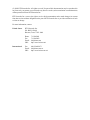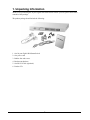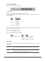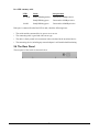
1
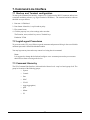
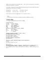
24-Port Gigabit Ethernet Switch
KGS-2401
Installation Guide
DOC.041223
-1-
(C) 2002 KTI Networks Inc. All rights reserved. No part of this documentation may be reproduced in
any form or by any means or used to make any directive work (such as translation or transformation)
without permission from KTI Networks Inc.
KTI Networks Inc. reserves the right to revise this documentation and to make changes in content
from time to time without obligation on the part of KTI Networks Inc. to provide notification of such
revision or change.
For more information, contact:
United States
International
KTI Networks Inc.
P.O. BOX 631008
Houston, Texas 77263-1008
Phone:
Fax:
E-mail:
URL:
713-2663891
713-2663893
[email protected]
http://www.ktinet.com/
Fax:
E-mail:
URL:
886-2-26983873
[email protected]
http://www.ktinet.com.tw/
-2-
The information contained in this document is subject to change without prior notice. Copyright (C). All Rights Reserved.
TRADEMARKS
Ethernet is a registered trademark of Xerox Corp.
WARNING:
This equipment has been tested and found to comply with the limits for a Class A digital device, pursuant to Part 15 of the FCC
Rules. These limits are designed to provide reasonable protection against harmful interference when the equipment is
operated in a commercial environment. This equipment generates, uses, and can radiate radio frequency energy and if not
installed and used in accordance with the instruction manual may cause harmful interference in which case the user will be
required to correct the interference at his own expense.
NOTICE:
(1) The changes or modifications not expressively approved by the party responsible for compliance could void the user's
authority to operate the equipment.
(2) Shielded interface cables and AC power cord, if any, must be used in order to comply with the emission limits.
CISPR A COMPLIANCE:
This device complies with EMC directive of the European Community and meets or exceeds the following technical standard.
EN 55022 - Limits and Methods of Measurement of Radio Interference Characteristics of Information Technology Equipment.
This device complies with CISPR Class A.
WARNING: This is a Class A product. In a domestic environment this product may cause radio interference in which case the
user may be required to take adequate measures.
CE NOTICE
Marking by the symbol
indicates compliance of this equipment to the EMC directive of the European Community. Such
marking is indicative that this equipment meets or exceeds the following technical standards:
EN 55022: Limits and Methods of Measurement of Radio Interference characteristics of Information Technology Equipment.
EN 50082/1:Generic Immunity Standard -Part 1: Domestic Commercial and Light Industry.
EN 60555-2: Disturbances in supply systems caused by household appliances and similar electrical equipment - Part 2:
Harmonics.
-3-
Table of Contents
1. Unpacking Information ............................................................................................. 6
2. Introduction to 24-port Gigabit Web Smart Switch ................................................ 7
2.1 General Description ............................................................................................................................... 7
2.2 Key Features .......................................................................................................................................... 7
2.3 The Front Panel ...................................................................................................................................... 8
2.4 The Rear Panel ...................................................................................................................................... 9
3. Installing 24-Port Gigabit Web Smart Switch ....................................................... 10
2.1 Desktop Installation ............................................................................................................................. 10
3.2 Rack-mount Installation ....................................................................................................................... 10
3.3 Installing Network Cables .................................................................................................................... 11
3.4 Network Application .............................................................................................................................. 11
4. Functional Description ........................................................................................... 12
4.1 PHY Monitoring and Port Mode Set-up ................................................................................................. 12
4.2 Flow Control ......................................................................................................................................... 12
4.3 Ageing ................................................................................................................................................... 12
4.4 VLAN ..................................................................................................................................................... 12
4.5 Link Aggregation .................................................................................................................................. 12
4.6 Quality of Service .................................................................................................................................. 12
5. Web Management guide ........................................................................................ 13
5.1 Access the Switch ................................................................................................................................ 13
5.2 Home Page .......................................................................................................................................... 14
5.2.1 System ............................................................................................................................................... 16
5.2.2 Ports .................................................................................................................................................. 17
5.2.3 VLAN .................................................................................................................................................. 18
5.2.4 Aggregation/ Trunking Configuration ................................................................................................ 20
5.2.5 QoS .................................................................................................................................................... 20
5.2.5.1 Quality of Service (QoS) TOS Configuration .................................................................................. 21
5.2.5.2 QoS Port Egress Rate Control ....................................................................................................... 22
5.2.5.3 QoS Port Ingress Rate Control ...................................................................................................... 22
5.2.5.4 QoS Port Broadcast Storm ............................................................................................................. 22
5.2.6 Mirror .................................................................................................................................................. 23
5.2.7 Statistics ............................................................................................................................................ 23
5.2.8 Discovery ........................................................................................................................................... 24
5.2.9 Default ............................................................................................................................................... 25
5.2.10 Reboot ............................................................................................................................................. 25
6. Product Specifications ........................................................................................... 26
7. Command Line Interface ........................................................................................ 27
7.1 Start-up and Terminal configuration .................................................................................................... 27
7.2 Login/Logout Procedures .................................................................................................................... 27
7.3 Command Hierarchy ............................................................................................................................ 27
7.4 Help Utility ............................................................................................................................................. 28
7.5 Entering Commands ............................................................................................................................ 29
-4-
7.6 Terminology .......................................................................................................................................... 30
7.7 Command Description ......................................................................................................................... 30
7.7.1 System Commands .......................................................................................................................... 31
7.7.2 Console Commands ........................................................................................................................ 32
7.7.3 Port Commands ................................................................................................................................ 32
7.7.4 MAC Table Commands ..................................................................................................................... 34
7.7.5 VLAN Commands ............................................................................................................................. 35
7.7.6 Aggregation/trunking Commands .................................................................................................... 36
7.7.7 QoS Commands ............................................................................................................................... 37
7.7.8 Mirror Commands ............................................................................................................................. 39
7.7.9 IP Commands ................................................................................................................................... 39
7.8 Example ................................................................................................................................................ 40
8. Factory Default Configuration ............................................................................... 41
-5-
1. Unpacking Information
Thank you for purchasing the 24-port Gigabit Web Smart Switch. Before you start, please check all the
contents of this package.
The product package should include the following:
1. One 24-port Gigabit Web Smart Switch
2. One power cord
3. Rubber foot and screws
4. Rack-mount brackets
5. One RS-232 Cable (Optional)
6. Product CD
-6-
2. Introduction to 24-port Gigabit Web Smart Switch
2.1 General Description
The device is a 24-port 10/100/1000Mbps Ethernet Web Smart Switch.
Compare to the traditional 10/100Mbps Ethernet, the switch delivers a dedicated Gigabit connection to
every attached client with no congestion issue. The gigabit ports also provide the fat pipe to the server
or backbone connectivity for boosting the total system performance. Moreover, the NWay auto-negotiation operation automatically negotiates with the connected partners on the network speed and duplex
mode; that provides an easy way to integrate 10/100/1000Mbps networks with no pain. It is ideal for
micro-segmenting large networks into smaller, connected subnets for improved performance, enabling
the bandwidth demanding multimedia and imaging applications.
Out of the ordinary dumb switches, the 24-port Gigabit Web Smart Switch embedded advanced management capability; that the device can be managed through console port or web-based UI. This is
much useful for system manager to monitor and control the system efficiently.
Store-and-forward switching mode promises the low latency plus eliminates all the network errors,
including runt and CRC error packets. To work under full-duplex mode, transmission and reception of
the frames can occur simultaneously without causing collisions as well as double the network bandwidth.
The switch is plug-n-play without any software to configure and also fully compliant with all kinds of
network protocols. Moreover, the rich diagnostic LEDs on the front-panel provide the operating status
of individual port and whole system.
2.2 Key Features
• 24 fixed 10/100/1000Mbps Gigabit Ethernet ports for easy network connecting application.
• Provide Auto-discovery Function for easy Network management.
• Provide 8K MAC address entries and 24 groups VLAN table
• Support up to 8 ports and 8 groups port aggregation.
• Support QoS-TOS, Egress rate control, Ingress rate control and Storm control for better Network
management.
• Support full duplex flow control and half duplex back pressure
• Store-and-forward forwarding scheme
• Error packet filtering
• Support Jumbo frame 9.6kbytes
• Supports 400K buffer Memory
• Support local Console port or Web-based UI for configuration
• Internal switching power supply (100-240Vac/50-60Hz)
-7-
2.3 The Front Panel
The front panel of the switch is shown as below:
Port Operation
There are 24 * 1000Mbps RJ-45 (copper) ports on the front panel.
The auto-negotiation feature of the switch allows each port of the device running at one of the following operation modes:
Speed
Duplex Mode
10Mbps
Full Duplex
Half Duplex
100Mbps
Full Duplex
Half Duplex
1000Mbps
Full Duplex
All ports supports MDI/MDI-X auto crossover capability that is the port can connect either the PC or
hub without crossover cable adjustment.
Wiring for 10/100/1000Mbps (Copper)
Following are the summaries of cabling required:
Media
Speed
Wiring
10/100/1000Mbps copper
10Mbps
Category 3,4,5 UTP/STP
100Mbps
Category 5 UTP/STP
1000Mbps Category 5,5e UTP/STP
LEDs Definition
The rich diagnostic LEDs on the front panel can provide the operating status of individual port and
whole system.
Power LED
This indicator lights green when the switch is receiving power; otherwise, it is
off.
Port LEDs
Every RJ-45 port on the front panel relevant two LEDs (10/100M; 1000Mbps)
for indicating the connection speed and activity status.
-8-
Port LED summary table
LEDs
Status
Interpretation
10/100M
Steady /Blinking Amber
Connected as 10Mbps/Active
Steady/Blinking green
Connected as 100Mbps/Active
Steady/Blinking green
Connected as 1000Mbps/Active
1000M
If the port is connected but the Port LED is dark, check the following items:
• The switch and the connected device power are on or not.
• The connecting cable is good and with correct type
• The cable is firmly seated in its connectors in the switch and in the associated device
• The connecting device, including any network adapter is well installed and functioning
2.4 The Rear Panel
The rear panel of the switch is shown as below:
-9-
3. Installing 24-Port Gigabit Web Smart Switch
This switch can be placed directly on your desktop, or mounted in a rack. Users can immediately use
most of the features simply by attaching the cables and turning the power on.
2.1 Desktop Installation
For desktop installation, the switch needs to put on a clean, flat desk or table close to a power outlet.
Plug in all network cables and the power cord, then the system is ready.
Before installing the switch, you must ensure:
1. It is accessible and cables can be connected easily
2. Cabling is away from:
• Sources of electrical noise such as radios, transmitters and broadband amplifiers
• Power lines and fluorescent lighting fixtures.
3. Keep water or moisture off
4. Airflow around the unit and through the vents in the side of the case is great for heat radiation
(company recommend that you provide a minimum of 25 mm clearance)
To prolong the operational life of your units:
1. Never stack unit more than eight sets high if freestanding
2. Do not place objects on top of any unit or stack
3. Do not obstruct any vents at the sides of the case
3.2 Rack-mount Installation
The switch may stand alone, or may be mounted in a standard 19-inch equipment rack. Rack mounting
produces an orderly installation when you have a number of related network devices. The switch is
supplied with rack mounting brackets and screws. These are used for rack mounting the unit.
Rack Mounting the Switch in the 19-inch rack:
1. Disconnect all cables from the switch before continuing.
2. Place the unit the right way up on a hard, flat surface with the front facing toward you.
3. Locate a mounting bracket over the mounting holes on one side of the unit.
4. Insert the screws and fully tighten with a suitable screwdriver.
5. Repeat the two previous steps for the other side of the unit.
6. Insert the unit into the 19" rack and secure with suitable screws (not provided).
7. Reconnect all cables.
-10-
3.3 Installing Network Cables
Station Connections
Reference to the wiring statement of the previous section; connect each station to the switch with
correct type of cables.
Switch-to-Switch Connections
In making a switch-to-switch connection, use every ports to connect another switch or backbone is
strongly recommended. The Gigabit ports provide the fat pipe to the server or backbone connectivity
for boosting the total system performance. Reference to the wiring statement of the previous section;
connect each station to the switch with correct type of cables.
Furthermore, as the switch supports Port Aggregation (Port Trunk) capability and up to 8 groups, it is
also great to build up switch-to-switch connectivity.
3.4 Network Application
-11-
4. Functional Description
4.1 PHY Monitoring and Port Mode Set-up
It is a major task of the software to continuously monitor the PHYs in order to set up the switch ports
according to whether the link is down or up and in the latter case what the current speed, duplex mode
and pause capabilities are.
PHYs are being polled every 100 ms.
4.2 Flow Control
In the 24-port switch flow control (back pressure) is also supported in half duplex. Flow control can be
enabled or disabled on a per-port basis from the command line interface.
If flow control is enabled for a port the associated PHY will be set to advertise support of Symmetric
Pause, but not Asymmetric Pause. If the station connected to the port also supports Symmetric
Pause, flow control will be enabled on the switch port.
4.3 Ageing
To prevent that an automatically learned MAC address of a station that has been detached will remain
in the MAC address table permanently, the ageing function in the switch is activated on a regular basis.
The period for doing the ageing function is determined by the ageing time parameter. The ageing time
parameter can be set from the command line interface. Default value is 300 seconds. Setting the
ageing time parameter to 0 disables the ageing function.
4.4 VLAN
The device supports 802.1Q tag based VLAN. With tagging to the header of packets, the network can
be segmented in groups to reduce the collisions from widely broadcasting. A maximum of 24 VLAN
groups can be stored in EEPROM. The VLAN look up is based on full 24-bit vlaue of packet VID or
Port PVID. It also provides egress tagging mode setting for each port.
4.5 Link Aggregation
Link aggregation groups (or channels) can be defined statically. LACP (Link Aggregation Control
Protocol) is not supported.
Maximum number of aggregation groups is 8.
The software will automatically detect that a link has gone down and then reassign packet distribution
on the other links in the group.
4.6 Quality of Service
Various classifications and prioritization such as TOS, Egress rate control, Ingress rate control and
Storm are supported in order to enable Quality of Service for real time applications such as VoIP
(Voice over IP).
-12-
5. Web Management guide
This section instructs you how to enter and set up the configurations, which can be accessed by RS232 serial port (out-of-band) on the rear panel or by Internet Browser over the network (in-band).
Factory Default value:
IP :
192.168.1.1
Subnet Mask:
255.255.255.0
Default Gateway: 192.168.1.254
5.1 Access the Switch
Console Port (Out-of-band) connection
The operating mode of the console port is:
•
•
•
•
•
•
DCE
115200 (Fix baud rate)
n (No parity checking)
8 (8 Data bits)
1 (1 stop bit)
None (No flow control)
After attaching a RS-232 cable (Straight-through) to the serial port of a PC running a terminal emulation program, press Enter key then login screen appears. Enter your username and password to login
the management console.
Note:
For the detail Command line Interface instructions, refer to the chapter 7.
Attention:
1. The factory default value of UserName and Password is admin.
2. System configurations via the Console Port only will be allowed by the way of master device.
In-Band Connections (Web Browser)
To manage the switch through in-band access, you should configure the management station with an IP
address and subnet mask compatible with your switch.
1. Running your Web Browser and enter the IP address 192.168.1.1 as the URL in the address
field.
2. Key in the User name and password to pass the authentication. The factory default value of
User Name and Password is admin.
-13-
3. After authentication procedure, the home page shows up.
5.2 Home Page
On the Home page, you can select the configuration by clicking the menu tabs located on the upside of
the UI. It includes,
!
!
!
!
!
!
!
!
System
Ports
VLAN
Aggregation
QoS
Mirror
Statistics
Discovery
-14-
To restore the default Values of switch, click the [Default] button. If you want to reboot the switch,
click the [Reboot] button. To check the connection status of each port from 1 to 24, take a look at the
port monitor. When the port shows green, it is connected and link up. Otherwise it is dark. To know
the detail statistics of one port, click on it and the window will show.
-15-
5.2.1 System
To set up the system configurations such as login value, time-out value and enabling the VLAN Management.
Status & Setting
Functions
Mac Address
The Mac Address of the switch
S/W Version
To check up the Software Version, see this.
H/W Version
The Hardware version
Inactivity Timeout (Secs)
Set the console inactivity timeout in seconds. The value zero disables timeout. Timeout value in seconds, 0, 60-10000.
System name
Name of the Switch
IP Address
Set up the IP of Switch
Subnet Mask
Set up the Subnet mask of Switch
Gateway
Set up the Gateway of Switch
Name
The Login name (default admin)
Password
The Login password (default admin)
Apply
Click this button to save the configuration.
Note:
After you change the IP address, the switch will reboot itself. You may click the new address to
link the New IP with your Browser.
-16-
5.2.2 Ports
On the page, you can view the Port status, set up the Speed mode and enable the FDX flow control.
Status & Settings
Functions
Link
To show the status of each port. When it is red, it means the connection is
down. Otherwise, it is green.
Mode
Choose the Speed mode of port 10/100/1000, Half/Full. To disable the port,
choose Disable. If you set to auto speed, it will be auto-negotiation.
FDX Flow Control
To Enable the FDX Flow control, click the check box.
Max Frame length
To adjust the Frame length, enter the value you need. The larger value it is,
the better network performance you will have. Default is 1518. The
Maximum value is 9600.
Apply
Click this button to save the configuration.
Refresh
Click this button to refresh the latest status of ports.
Note:
To make the maximum frame length control works properly, FDX Flow Control of the port must
be enabled. The port link partner must also be enabled for supporting flow control.
-17-
5.2.3 VLAN
VLAN Configuration is for dividing the LAN into subnet groups for better network management. The
benefit is that the user can move one client to another subnet group without actually moving the machine.
VLAN Entry
There are 24 entries to set up.
To add new VLAN Entry,
1. Select the ports by clicking the check box.
2. Enter the VLAN ID number (1 ~ 4094) for the entry.
3. Select the member ports (PORT MEMBER) for the new VLAN entry.
4. Click [Add] to add it in the table.
5. Do not forget to click the [Apply] to save the setting.
To remove the VLAN entry,
Select the entry you want to remove, click [Remove] to delete it.
Note:
If the entry VID (VLAN ID) value exists in any port PVID configuration, the entry can not be
removed.
To modify the entry,
Select the entry you want to change and set up the new configurations. After the changes are made,
Click [Modify] to save.
Caution:
Because settings in VLAN, Port aggregation, and Mirror functions are correlative, make sure
that the setting will not influence others. It is suggested not to activate more than one function for
one port.
-18-
PVID
When the VLAN-enabled switch receives a untagged packet, the packet will be sent to the port default
VLAN according to the PVID (port VLAN ID) of the ingress port.
Settings
Functions
Port
Port Number 1~24
PVID
Port VLAN ID(1~4094)
For Ingress VLAN mapping rules, refer to the following table:
Only Tagged
EgressTagging
Received Packet Type VLAN entry mapped
Disable
Untagged
Ingress port PVID
Disable
Tagged
Received packet VID
Enable
Untagged
Drop received packet
Enable
Tagged
Received packet VID
Check the box to enable egress tagging before packet transmission.
For the detail egress tagging rules, refer to the following table:
Tagging
Disable
Enable
Received Packet Egress Packet
Untagged
Untagged (no modification)
Tagged
Untagged (VID tag is removed)
Untagged
Insert VID Tag with ingress port PVID
Tagged
Tagged (no modification)
Only Tagged
Check box to enable the port to drop all received untagged frames
Apply
Click button to save the changes you made.
-19-
5.2.4 Aggregation/ Trunking Configuration
To set up the Port trunk groups, put the ports number into the same Aggregation group line. There are
eight groups to choose. The maximum number of ports for one group is 8.
There three aggregation modes for selection, SMAC (Source MAC), DMAC (Destination MAC), and
XOR.
5.2.5 QoS
The switch provides four functions for Quality of Service. They are custom TOS, Egress Rate Control,
Ingress Rate Control, and Custom Storm.
-20-
5.2.5.1 Quality of Service (QoS) TOS Configuration
To improve the network performance by applying the TOS for IP packets, set up the priority of eight
groups of precedence bits on this page. There are two priority levels to choose, high or Low.
Settings
Functions
Port
To select the switch port, from 1 to 24
Bit 0-2
TOS bit value
Priority
Select the priority of TOS group
The following table lists the type of Precedence for TOS values:
TOS Value Precedence
111
Network Control
110
Internetwork Control
101
CRITIC/ECP
100
Flash Override
011
Flash
010
Immediate
001
Priority
000
Routine
-21-
5.2.5.2 QoS Port Egress Rate Control
To limit the out-going packet rate, select [Enable] and enter the value you need from 250~1000000K
bps. The packet rate over the limitation will be discarded. Click [Apply] to save settings.
5.2.5.3 QoS Port Ingress Rate Control
To limit the in-coming packet rate, select [Enable] and enter the value you need from 250~1000000K
bps. If the packet rate is larger than the limitation, the switch will make the connected device on the
port to suspend the frame transmission by using flow control mechanism. Click [Apply] to save settings.
5.2.5.4 QoS Port Broadcast Storm
To prevent the broadcast storm, the switch provides the multicast packet rate control setting. You can
select [Enable] and enter the value, and click [Apply] to save the setting.
-22-
5.2.6 Mirror
Port mirror function is used to mirror traffic from source port to a target port for analysis. Only 2 ports
can be monitored (mirrored) simultaneously to 1 Monitor port (target port). (Note that the target port
must be in the same VLAN as the source ports.)
Settings
Functions
Monitor Port
Select the switch port, from 1 to 24 to be the target port to collect traffic info
Source Ports
To select the mirror ports, Click the check box of the port.
Apply
Click button to save settings.
5.2.7 Statistics
To check the status of port traffic, click statistic tab. You can click [Clear] button to erase all records
or click [Refresh] to show the latest status.
-23-
5.2.8 Discovery
When you install several switches in the network, the discovery management tool helps you to search
and access those switches easily. Therefore you can access any switch without memorizing the respective IP addresses.
Note:
The Maximum number of Address list is 16 for each mode.
Auto Search
1. Click the Auto search [Apply] button to find the switches.
2. The IP address & name of Switch list will appear.
3. Click the one you want to access.
Manual Add
1. Enter the IP address & name in the text box
2. Click [Add] to add the new IP address on the table
Remove
1. Click the check box of the switch you want to remove from the list.
2. Click [Delete] to remove.
-24-
5.2.9 Default
To restore all settings to factory default values,
1. Click [Default] button on the Home page
2. Click [Yes] to confirm the action.
5.2.10 Reboot
To reboot the switch,
1. Click [Reboot] button on the Home page
2. Click [Yes] to confirm the action.
-25-
6. Product Specifications
Standard
IEEE802.3 10BASE-T
IEEE802.3u 100BASE-TX
IEEE802.3x full-duplex operation and flow control
IEEE802.3ab 1000BASE-T
IEEE802.1Q VLAN interoperability
Interface
24 * 10/100/1000Mbps auto MDI/MDI-X RJ-45 switching ports
1 * RS-232 Console port
Cable Connections
RJ-45 (10BASE-T): Category 3,4,5 UTP/STP
RJ-45 (100BASE-TX): Category 5 UTP/STP
RJ-45 (1000BASE-T): Category 5,5e or enhanced UTP/STP
Network Data Rate
10/100/1000Mbps Auto-negotiation
Transmission Mode
10/100Mbps Full-duplex, Half-duplex
1000Mbps Full-duplex
LED indications
System Power
RJ-45 Port 10/100M; 1000M link/act
Memory
8K MAC entries
400K Buffer Memory
Emission
FCC Class A, CE
Operating Temperature 00 ~ 500C (320 ~ 1220F)
Operating Humidity
10% - 90%
Power Supply
Internal power supply 5V 10A 100-240V/ 50-60H
Power Consumption
43W max.
-26-
7. Command Line Interface
7.1 Start-up and Terminal configuration
To start-up the command line interface, connect a PC COM port to the RS-232 connector and activate
a terminal emulation software (e.g. HyperTerminal of Windows.). The terminal emulation software
should be set up as follows:
1. Data rate: 115200 baud
2. Data format: 8 data bits, 1 stop bit and no parity
3. Flow control: none.
4. Click the property icon, select settings, make sure that:
The Function, arrow, and ctrl keys act as: Terminal keys
Emulation: VT100
7.2 Login/Logout Procedures
To get access to the CLI, you will have to get the username and password for login. One set of default
username/password is identified with admin/admin.
You may logout at any time and at any context level using the exit command.
Note:
It is suggested to change the default and configure a new username/password to prevent unauthorized users from accessing to the device.
7.3 Command Hierarchy
The CLI (Command Line Interface) is hierarchical with two levels: a top level and a group level. The
group level consists of the following groups:
• System
•
Console
•
Port
•
MAC
•
VLAN
•
Aggr(Aggregation)
•
QoS
•
Mirror
•
IP
-27-
When you are at the top level, the prompt shows :>, and if you are at the group level, the prompt
displays the group name, e.g. System>.
To be under a certain group, you may enter the group name at top level or add / in front of the group
name then press enter at any level. Examples:
At top level:
>system <enter>
New prompt -> System>
At any level:
system>/ip <enter>
New prompt -> IP>
To be at top level, you may enter up at any level. (ex, system>up <enter>).
Note:
All the characters entered in the command line interface are NOT case-sensitive.
7.4 Help Utility
You can get command information by entering ? or help.
Prompt at top level
System
Console
Port
MAC
VLAN
Aggregation
QoS
Mirror
IP
System commands
Console commands
Port commands
MAC table commands
VLAN commands
Aggregation/Trunking commands
QoS commands
Mirror commands
IP commands
Prompt at group level (Example: System>? <enter>)
System
System
System
System
System
System
Configuration [all]
Restore default [keepip]
UserName [<name>]
Password [<password>]
systemname [<systemname>]
Reboot
Help after a specific command (Example: System>configuration ?)
Syntax:
System Configuration [all]
Description:
Show System Name, Username, Password, Software Version, Hardware Version
and management MAC address. Optionally show the full configuration
[all]: Show the total switch configuration (default: System configuration
only)
-28-
7.5 Entering Commands
Commands are given by entering the command string. The command string is not case-sensitive.
There are three possible situations for entering the command:
1. At any level or group: you should enter the full syntax of the command with a / in front of the
syntax (ex, enter /system configuration in any level to check the system status.)
2. At top level or under the group that contains the command: enter the full command syntax (ex,
enter system configuration at top level or at prompt System>)
3. Under the group that contains the command: Users are allowed to enter the command skipping
the group name (ex, enter configuration under the prompt System>)
Some of the commands have optional parameters (parenthesized after a syntax). If the optional parameter is omitted, a default value may be used or the command may display the current setting (i.e.
functions as a getting a command).
Example 1, omitted parameter interpreted as display command:
Syntax:
Systemname [<systemname>]
System>systemname <enter>
systemname: giga-switch
Example 2, omitted parameter interpreted as default value (VLAN ID 1):
Syntax:
MAC Add <macaddress> <portlist> [<vid>]
>mac add 010203ABCDEF 16 <enter>
You may use the horizontal arrow-keys <- and -> to move the cursor within the command you are
entering. And you can also use the backspace key (provided by a terminal that sends the BS (8)
character when the backspace key is pressed) to delete characters from the command you are entering.
If your terminal software (e.g. HyperTerminal) supports <home> and <end> keys, you may use these
keys to move the cursor to respectively the start and the end of the command line.
-29-
7.6 Terminology
The following table shows general parameter types used in command syntaxes and descriptions.
<port>
The port number
<portlist>
Comma and/or dash separated port list. This type can be used for specifying
individual ports or a range of ports. The keyword none can be used to specify an
empty port list. The keyword all can be used to specify all ports. Example: 1,3,812.
<macaddress>
MAC Address; format: hh-hh-hh-hh-hh-hh, hh:hh:hh:hh:hh:hh or
hhhhhhhhhhhh. The hh is Hexadecimal number in the range 0x00 to 0xFF.
Example: 00-00-24-F1-02-03
<vid>
VLAN ID: Decimal number in the range 1-4095. The keyword all can be used
to specify all VLAN IDs.
<vidlist>
Comma and/or dash separated VLAN ID list. This type can be used for specifying individual VLAN IDs or a range of VLAN IDs. The keyword none can be
used to specify an empty VLAN ID list. Example: 1,2,4-6
<UDP/TCP port> UDP/TCP port number: Decimal number in the range 0-65535.
<rate>
Leaky bucket rate in Kbit/s [0-1000000k] or Mbit/s [0-1000m]
The <portlist> type is helpful when setting up multiple ports in the same mode. For example, the
following commands divide the ports into two untagged VLANs and enable VLAN awareness:
vlan
vlan
vlan
vlan
vlan
add 1 1-8
add 2 9-16
pvid 1-8 1
pvid 9-16 2
aware all enable
7.7 Command Description
In this session, the commands in each group and the descriptions to those commands are provided
respectively in the following group order:
1. System
2. Console
3. Port
4. MAC
5. VLAN
6. Aggregation
7. QoS
8. Mirror
9. IP
-30-
7.7.1 System Commands
Commands at the System level:
System
System
System
System
System
System
Configuration [all]
Restore default [keepip]
UserName [<name>]
Password [<password>]
systemname [<systemname>]
Reboot
1. System Configuration:
Syntax:
System Configuration [all]
Description:
Show system name, software version, hardware version and management MAC
address. Optionally show the full configuration
[all]: Show the total switch configuration (default: System configuration
only).
2. System Restore default
Syntax:
System Restore Default
Description:
Restore factory default configuration.
[keepip]: Keep current IP settings.
3. System Username
Syntax:
UserName [<name>]
Description:
Set or show the user name.
4. System Password
Syntax:
Password [<password>]
Description:
Set or show the password. The password can not be empty.
[<password>]: Password string of up to 16 characters
5. Systemname
Syntax:
Systemname [<systemname>]
Description:
Set or show the system name. The systemname can not be empty.
[<systemname>]: String of up to 16 characters.
6. System Reboot
Syntax:
-31-
System Reboot
Description:
Reboot the switch.
7.7.2 Console Commands
Commands at Console level:
Console Configuration
Console Timeout [<timeout>]
Console Prompt [<prompt string>]
1.Console Configuration
Syntax:
Console Configuration
Description:
Show configured Console password and timeout.
2. Console Timeout
Syntax:
Console Timeout [<timeout>]
Description:
Set or show the Console inactivity timeout in seconds. The value zero
disables timeout.
[<timeout>]: Timeout value in seconds, 0, 60-10000.
3. Console Prompt
Syntax:
Console Prompt [<prompt_string>]
Description:
Set or show the Console prompt string. The empty string (“”) clears the
prompt string.
[<prompt_string>]: Command prompt string of up to 10 characters.
7.7.3 Port Commands
Commands at Port level:
Port
Port
Port
Port
Port
Port
Configuration [<portlist>]
Mode [<portlist>] [<mode>]
Flow Control [<portlist>] [enable|disable]
State [<portlist>] [enable|disable]
MaxFrame [<portlist>] [<framesize>|reset]
Statistics [<portlist>] [clear]
1. Port Configuration
Syntax:
Port Configuration [<portlist>]
Description:
Show the configured and current speed, duplex mode, flow control mode and
state for the port.
-32-
<portlist>: Port list (Default: All ports).
2. Port Mode
Syntax:
Port Mode [<portlist>] [<mode>]
Description:
Set or show the speed and duplex mode for the port.
<portlist>: Port list (Default: All ports).
<mode> : Port speed and duplex mode (Default: Show configured and current
mode).
10hdx : 10 Mbit/s, half duplex.
10fdx : 10 Mbit/s, full duplex.
100hdx : 100 Mbit/s, half duplex.
100fdx : 100 Mbit/s, full duplex.
1000fdx: 1 Gbit/s, full duplex.
auto : Auto negotiation of speed and duplex.
3. Port Flow Control
Syntax:
Port Flow Control [<portlist>] [enable|disable]
Description:
Set or show flow control mode for the port.
<portlist> : Port list (default: All ports).
[enable|disable]: Enable/disable flow control (default: Show flow control
mode).
4. Port State
Syntax:
Port State [<portlist>] [enable/disable]
Description:
Set or show the state for the port.
<portlist> : Port list (default: All ports).
[enable|disable]: Enable or disable port state (default: Show state).
5. Port MaxFrame
Syntax:
Port MaxFrame [<portlist>] [<framesize>|reset]
Description:
Set or show the maximum frame size in bytes (including FCS) for frames
received on the port. Tagged frames are allowed to be 4 bytes longer than
the maximum frame size. Use the reset option to return to the default
setting.
[<portlist>] : Port list (default: All ports).
[<framesize>|reset]: Maximum frame size or reset to 1518 bytes (default:
Show maximum frame size).
6. Port Statistics
Syntax:
Port Statistics [<portlist>] [clear]
Description:
-33-
Show or clear statistics for the port.
<portlist>: Port list (default: All ports).
[clear] : Clear port statistics (default: Show statistics).
7.7.4 MAC Table Commands
Commands at MAC level:
MAC
MAC
MAC
MAC
MAC
MAC
Configuration
Add <macaddress> <portlist>|none [<vid>]
Delete <macaddress> [<vid>]
Lookup <macaddress> [<vid>]
Flush
Agetime [<agetime>]
1. MAC Configuration
Syntax:
MAC Configuration
Description:
Show the permanently stored MAC table and the MAC ageing timer.
2. MAC Add
Syntax:
MAC Add <macaddress> <portlist>|none [<vid>]
Description:
Add a static MAC address table entry and VLAN ID on ports.
<macaddress>: MAC address, 12-digit hex string, optionally separated with
dashes or colons (e.g. 010203ABCDEF or 01-02-03-AB-CD-EF or
01:02:03:AB:CD:EF).
<portlist> : Port list. Use ”none” to specify no ports.
[<vid>] : VLAN ID, 1-4094 (default: 1).
3. MAC Delete
Syntax:
MAC Delete <macaddress> [<vid>]
Description:
Delete MAC address and VLAN ID.
<macaddress>: MAC address, 12-digit hex string, optionally separated with
dashes or colons (e.g. 010203ABCDEF or 01-02-03-AB-CD-EF or
01:02:03:AB:CD:EF).
[<vid>] : VLAN ID (default: 1).
4. MAC Lookup
Syntax:
MAC Lookup <macaddress> [<vid>]
Description:
Lookup MAC address and VLAN ID.
<macaddress>: MAC address, 12-digit hex string, optionally separated with
dashes or colons (e.g. 010203ABCDEF or 01-02-03-AB-CD-EF or
01:02:03:AB:CD:EF).
[<vid>] : VLAN ID, 1-4094 (default: 1).
-34-
5. MAC Flush
Syntax:
MAC Flush
Description:
Removes non-static MAC address from the switch MAC table.
6. MAC Age Time
Syntax:
MAC Agetime [<agetime>]
Description:
Set or show the MAC age timer in seconds. The value zero disables ageing.
[<agetime>]: Age timer in seconds, 0 or 10-65535 (default: Show timer).
7.7.5 VLAN Commands
Commands at VLAN level:
VLAN
VLAN
VLAN
VLAN
VLAN
VLAN
VLAN
VLAN
Configuration [<portlist>]
Add <vidlist> [<portlist>]
Modify <vidlist> [<portlist>]
Delete <vidlist>
Lookup <vidlist>
Aware [<portlist>] [enable|disable]
PVID [<portlist>] [<vid>|none]
Frame Type [<portlist>] [all|tagged]
1. VLAN Configuration
Syntax:
VLAN Configuration [<portlist>]
Description:
Show the VLAN aware mode, port VLAN ID and accepted frame type for the
port
and the permanently stored VLAN table.
[<portlist>]: Port list (default: All ports).
2. VLAN Add
Syntax:
VLAN Add <vidlist> [<portlist>]
Description:
Add VLAN entry and include ports in member set.
<vidlist> : VLAN ID list.
[<portlist>]: Port list (default: All ports).
3. VLAN Delete
Syntax:
VLAN Delete <vidlist>
Description:
Delete VLAN entry (all ports excluded from member set).
<vidlist> : VLAN ID list.
-35-
4. VLAN Lookup
Syntax:
VLAN Lookup <vidlist>
Description:
Lookup VLAN entry and show port list.
<vidlist> : VLAN ID list.
5. VLAN EgressTagging
Syntax:
VLAN EgressTagging [<portlist>] [enable|disable]
Description:
Set or show the VLAN Egress Tagging mode for the port. The enabled ports
will strip the VLAN tag from received frames and insert the tag in transmitted frames (except PVID). The disabled ports will not strip the tag
from received frames or insert the tag in transmitted frames.
[<portlist>]: Port list (default: All ports).
[enable|disable]: Enable/disable VLAN egress tagging (default: Show
awareness).
6. VLAN PVID
Syntax:
VLAN PVID [<portlist>] [<vid>|none]
Description:
Set or show the port VLAN ID. Untagged frames received on the port will
be classified to this VLAN ID. Frames classified to this VLAN ID will be
sent untagged on the port.
[<portlist>]: Port list (default: All ports).
[<vid>|none]: Port VLAN ID, 1-4094 (default: Show PVID).
The none option can be used for trunk links.
7. VLAN Frame Type
Syntax:
VLAN Frame Type [<portlist>] [all|tagged]
Description:
Set or show the accepted frame type for the port.
[<portlist>]: Port list (default: All ports).
[all|tagged]: Accept all or only tagged (default: Show frame type).
7.7.6 Aggregation/trunking Commands
Commands at Aggr level:
Aggr
Aggr
Aggr
Aggr
Aggr
Configuration
Add <portlist>
Delete <portlist>
Lookup <portlist>
Mode [smac|dmac|xor]
1. Aggregation Configuration
Syntax:
-36-
Aggr Configuration
Description:
Shows the aggregation groups and the aggregation mode.
2. Aggregation Add
Syntax:
Aggr Add <portlist>
Description:
Add link aggregation group including ports.
<portlist>: Aggregation port list.
3. Aggregation Delete
Syntax:
Aggr Delete <portlist>
Description:
Delete link aggregation group.
<portlist>: Port list. Aggregations including any of the ports will be
deleted.
4. Aggregation Lookup
Syntax:
Aggr Lookup <portlist>
Description:
Lookup and display link aggregation group.
<portlist>: Port list. Aggregations including any of the ports will be
shown.
5. Aggregation Mode
Syntax:
Aggr Mode [smac|dmac|xor]
Description:
Set or show link aggregation traffic distribution mode.
[smac|dmac|xor]: Aggregation mode, SMAC, DMAC or XOR (default: Show
mode).
7.7.7 QoS Commands
Commands at QoS level:
QoS
QoS
QoS
QoS
QoS
Configuration [<portlist>]
TosPrecedence [<portlist>] [<tosprecedencelist>] [low|high]
EgressRate [<portlist>] [enable|disable] [<rate>]
IngressRate [<portlist>] [enable|disable] [<rate>]
Storm Control [<portlist>] [enable|disable] [<rate>]
1. QoS Configuration
Syntax:
QoS Configuration [<portlist>]
Description:
Show the configured IP ToS Precedence priority mapping, egress rate con-37-
trol
configuration, ingress rate control configuration and multicast storm
control
[<portlist>]: Port list (default: All ports).
2. QoS Tosprecedence
Syntax:
QoS Tosprecedence [<portlist>] [<tosprecedencelist>] [low|high]
Description:
Set or show the IP ToS precendence priority mapping.
[<portlist>] : Port list (default: All ports).
[<tosprecedencelist>]: IP ToS precedence list, 0-7 (default: All precedence values).
[low|high] : Internal priority (default: Show priority).
3. QoS Egress Rate
Syntax:
QoS EgressRate [<portlist>] [enable|disable] [<rate>]
Description:
Set or show the Egress rate configuration.
[<portlist>] : Port list (default: All ports).
[enable|disable]: Enable/disable Egress Rate control (default: Show
shaper mode).
[<rate>] : Leaky bucket rate in Kbit/s [250-1000000k] or Mbit/s[1-1000m]
(default: Show EgressRate rate).
4. QoS Ingress Rate
Syntax:
QoS IngressRate [<portlist>] [enable|disable] [<rate>]
Description:
Set or show the ingress rate configuration.
[<portlist>] : Port list (default: All ports).
[enable|disable]: Enable/disable ingress rate control (default: Show
IngressRate mode).
[<rate>] : Leaky bucket rate in Kbit/s [250-1000000k] or Mbit/s [1-1000m]
(default: Show Ingress rate).
5. QoS Storm Control
Syntax:
QoS Storm Control [<portlist>] [enable|disable] [<rate>]
Description:
Set or show the multicast storm control configuration. Multicasts and
broadcasts are controlled using a multicast ingress rate control.
[<portlist>] : Port list (default: All ports).
[enable|disable]: Enable/disable the multicast ingress rate control (default: Show multicast IngressRate mode).
[<rate>] : Leaky bucket rate in Kbit/s [250-1000000k] or Mbit/s [1-1000m]
(default: Show multicast Ingress rate).
-38-
7.7.8 Mirror Commands
Commands at Mirror level:
Mirror Configuration
Mirror Port [<port>]
Mirror Source [<portlist>] [enable|disable]
1. Mirror Configuration
Syntax:
Mirror Configuration
Description:
Show the mirror destination port and mirror mode for source ports.
2. Mirror Port
Syntax:
Mirror Port [<port>]
Description:
Set or show the mirror destination port.
[<port>]: Mirror destination port (default: Show mirror port).
3. Mirror Source
Syntax:
Mirror Source [<portlist>] [enable|disable]
Description:
Set or show the source port mirror mode.
[<portlist>] : Source port list (default: All ports).
[enable|disable]: Enable/disable mirroring of frames received on port
(default: Show mirror mode).
7.7.9 IP Commands
Commands at IP level:
IP Configuration
IP Setup [<ipaddress> [<ipmask> [<ipgateway>]]]
1. IP Configuration
Syntax
IP Configuration
Description:
Show the IP status, including IP, Subnet Mask, and Default Gateway
2. IP Setup
Syntax
IP Setup [<ipaddress> [<ipmask> [<ipgateway>]]]
Description:
Set the IP, Subnet Mask, and Default Gateway
-39-
7.8 Example
This example shows how to configure two VLANs with the following setup:
• VID 1 spans ports 2-16 and VID 2 spans ports 1-3, so port 2 and 3 are members of both VLANs
and all 16 ports must be VLAN Egress Tagging enabled.
• Port 1 is the access port for VID 2, so PVID of port 1 must be set to 2.
• Port 2 is the trunk port for VID 1 and VID 2, so the PVID of port 2 must be set to none and
port 2 must be set to accept tagged frames only
• Port 3 is the hybrid port for VID 1 and VID 2, where VID 1 is the untagged VLAN, so PVID
must be set to 1.
• Ports 4-16 are access ports for VID 1.
The following CLI session does the above setup provided that the initial configuration is the default
configuration:
>vlan
VLAN>add 1 2-16
*** Warning: Existing entry overwritten
VLAN>add 2 1-3
VLAN>egresstagging enable
VLAN>pvid 1 2
VLAN>pvid 2 none
VLAN>frame type 2 tagged
VLAN>conf
VLAN Configuration:
Port
EgressTagging PVID
FrameType
1:
enabled
2
All
2:
enabled
none
Tagged
3:
enabled
1
All
4:
enabled
1
All
5:
enabled
1
All
6:
enabled
1
All
7:
enabled
1
All
8:
enabled
1
All
9:
enabled
1
All
10:
enabled
1
All
11:
enabled
1
All
12:
enabled
1
All
13:
enabled
1
All
14:
enabled
1
All
15:
enabled
1
All
16:
enabled
1
All
Entries in permanent table:
1: 2,3,4,5,6,7,8,9,10,11,12,13,14,15,16
2: 1,2,3
VLAN>
-40-
8. Factory Default Configuration
The factory default configuration is a VLAN aware L2 switch with automatic learning/ageing and auto
negotiation enabled on all ports:
System:
The system name string is empty.
Console:
The password string is empty and inactivity timeout is disabled. The prompt is >.
Port:
All ports are enabled for auto negotiation and flow control is disabled. Max
frame size is 1518.
MAC table:
The table is empty, auto learning and ageing is enabled. The ageing timer is 300
seconds.
VLAN:
Only VLAN 1 is present in the table and includes all ports. All ports are VLAN
egress tagging disabled with Port VLAN ID 1. All ports accept all frame types.
Aggregation:
No ports are aggregated, but aggregation mode is set to XOR.
QoS:
IP ToS Precedence priority is enabled and all Precedence values are given high
priority. The 4 highest VLAN tag priorities are given high priority. The UDP/
TCP port list is empty. Default priority is high. Default user priority is 0. L4
default priority and match priority are low. All EgressRate control and
IngressRate control are disabled.
Mirror:
Mirroring is disabled.
-41-