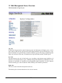
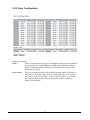
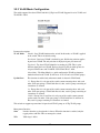
1
KGS-2402
Web Samrt 24-Port Gigabit Ethernet Switch
with SFP support
Installation Guide
DOC.050724
-1-
(C) 2005 KTI Networks Inc. All rights reserved. No part of this documentation may be reproduced in
any form or by any means or used to make any directive work (such as translation or transformation)
without permission from KTI Networks Inc.
KTI Networks Inc. reserves the right to revise this documentation and to make changes in content
from time to time without obligation on the part of KTI Networks Inc. to provide notification of such
revision or change.
For more information, contact:
United States
International
KTI Networks Inc.
P.O. BOX 631008
Houston, Texas 77263-1008
Phone:
Fax:
E-mail:
URL:
713-2663891
713-2663893
[email protected]
http://www.ktinet.com/
Fax:
E-mail:
URL:
886-2-26983873
[email protected]
http://www.ktinet.com.tw/
-2-
The information contained in this document is subject to change without prior notice. Copyright (C). All
Rights Reserved.
TRADEMARKS
Ethernet is a registered trademark of Xerox Corp.
WARNING:
This equipment has been tested and found to comply with the limits for a Class A digital device, pursuant
to Part 15 of the FCC Rules. These limits are designed to provide reasonable protection against harmful
interference when the equipment is operated in a commercial environment. This equipment generates,
uses, and can radiate radio frequency energy and if not installed and used in accordance with the
instruction manual may cause harmful interference in which case the user will be required to correct the
interference at his own expense.
NOTICE:
(1) The changes or modifications not expressively approved by the party responsible for compliance
could void the user's authority to operate the equipment.
(2) Shielded interface cables and AC power cord, if any, must be used in order to comply with the
emission limits.
CISPR A COMPLIANCE:
This device complies with EMC directive of the European Community and meets or exceeds the following
technical standard.
EN 55022 - Limits and Methods of Measurement of Radio Interference Characteristics of Information
Technology Equipment. This device complies with CISPR Class A.
WARNING: This is a Class A product. In a domestic environment this product may cause radio interference in which case the user may be required to take adequate measures.
CE NOTICE
Marking by the symbol
indicates compliance of this equipment to the EMC directive of the Euro-
pean Community. Such marking is indicative that this equipment meets or exceeds the following technical standards:
EN 55022: Limits and Methods of Measurement of Radio Interference characteristics of Information
Technology Equipment.
EN 50082/1:Generic Immunity Standard -Part 1: Domestic Commercial and Light Industry.
EN 60555-2: Disturbances in supply systems caused by household appliances and similar electrical
equipment - Part 2: Harmonics.
-3-
Table of Contents
1. Introduction ................................................................................................... 6
1.1 Features .................................................................................................................... 6
1.2 View of Web Smart 24-Port Gigabit Switch ............................................................... 7
1.3 Hardware Specifications ........................................................................................... 8
1.4 Management Software Specifications ....................................................................... 9
2. Installation ................................................................................................... 10
2.1 Safety Cautions ....................................................................................................... 10
2.2 Desktop Mounting .................................................................................................... 10
2.3 Applying Power ........................................................................................................ 10
2.4 SFP Transceiver Installation .................................................................................... 10
2.5 Port and Cable ........................................................................................................ 11
2.6 Rack Mounting ......................................................................................................... 11
2.7 RESET Button ......................................................................................................... 11
2.8 Software Management ............................................................................................ 11
2.9 IP Address Settings and Changing Password ........................................................ 11
3. Operation of Web-based Management ..................................................... 12
3.1 Web Management Home Overview ........................................................................ 13
3.2 Configuration ........................................................................................................... 14
3.2.1 System Configuration ........................................................................................... 15
3.2.2 Ports Configuration ............................................................................................... 16
3.2.3 VLAN Mode Configuration ..................................................................................... 17
3.2.4 VLAN Group Configuration.................................................................................... 18
3.2.5 PVID Configuration ............................................................................................... 20
3.2.6 Aggregation Configuration .................................................................................... 21
3.2.7 Mirror Configuration .............................................................................................. 22
3.2.8 Quality of Service Configuration ........................................................................... 23
3.2.8.1 Vlan Tag Configuration ....................................................................................... 24
3.2.8.2 IP ToS Classification .......................................................................................... 25
3.2.8.3 IP TCP/UDP Port Classification ........................................................................ 26
3.2.8.4 IP Diffserv Classification.................................................................................... 28
3.2.9 Bandwidth Management ....................................................................................... 29
3.2.10 Trap Event Configuration .................................................................................... 30
3.2.11 Max. Packet Length ............................................................................................ 31
-4-
3.3 Monitoring ................................................................................................................ 32
3.3.1 Statistics Overview ............................................................................................... 32
3.3.2 Detailed Statistics ................................................................................................. 33
3.4 Maintenance ............................................................................................................ 35
3.4.1 Status ................................................................................................................... 35
3.4.2 Warm Restart ....................................................................................................... 37
3.4.3 Factory Default ..................................................................................................... 38
3.4.4 Software Update ................................................................................................... 39
3.4.5 Logout .................................................................................................................. 40
-5-
1. Introduction
Before you start installing the switch, verify that the package contains the following:
• Web Smart 24-Port 10/100/1000 Gigabit Ethernet Switch unit
• 19" rack mounting brackets
• This User Manual in CD-ROM
• AC Power Cord
1.1 Features
•
•
•
•
•
•
•
•
•
•
•
Non-blocking store-and-forward Web-Smart switched.
24 10/100/1000Mbps Auto-negotiation Gigabit Ethernet copper ports
2 1000Mbps Gigabit Ethernet fiber ports (support dual media types, fiber and copper)
400KB on-chip frame buffer
Jumbo frame support
Diversified classification supports for QoS (even L4 support)
8K MAC address and 4K VLAN support (IEEE802.1Q)
Per-port bandwidth rate control and Broadcast Storm Control
IEEE802.1Q VLAN support
Full-duplex flow control (IEEE802.3x) and half-duplex backpressure
Extensive front-panel diagnostic LEDs; System: Power, Copper Port1-24: LINK/ACT, 10/100/
1000Mbps and SFP LINK/ACT
Management
• Supports concisely the status of port and easily port configuration
• Supports per port traffic monitoring counters
• Supports port mirror function
• Supports the static trunk function
• Supports 802.1Q VLAN
• Supports user management and limits one user to login
• Maximal packet length can be up to 9216 bytes for jumbo frame application
• Supports Broadcasting Suppression to avoid network suspended or crashed
• Supports to send the trap event while monitored events happened
• Supports default configuration which can be restored to overwrite the current configuration
which is working on via Web UI and Reset button of the switch
• Supports on-line plug/unplug SFP modules
• Supports Quality of Service (QoS) for real time applications based on the information taken from
Layer 2 to Layer 4, such as VoIP
• Built-in web-based management with convenient GUI for the user
-6-
1.2 View of Web Smart 24-Port Gigabit Switch
The major user interface components on the front panel and rear panel are:
• LED indicators
LED Display for system power status and port status
• 10/100/1000M copper ports
Gigabit copper ports (Port 1 - Port 24)
• 1000M SFP fiber ports
Gigabit fiber ports with SFP connectors (Port 23, Port 24)
• RESET button
Button for reboot the switch or reset the switch to factory defaults
• AC power socket
Power socket for AC power cord
LED
System POWER
Color
Green
Function
ON - when +5V DC power is on and good
Port 1 to 24 LINK/ACT
Green
ON - when connection with remote device is good
Blink - when any traffic is present
Off - when cable connection is not good
Port 1 to 24 10/100/1000Mbps Green/Ember
ON - green when 1000Mbps speed is active
ON - ember when 100Mbps speed is active
Off - when 10Mbps speed is active
Port 23, 24 SFP
Green
ON - when connection with remote device is good
Blink - when any traffic is present
Off - when cable connection is not good
-7-
1.3 Hardware Specifications
Standard Compliance: IEEE802.3/802.3ab / 802.3z / 802.3u / 802.3x
Network Interface:
Configuration
Mode
Connector
Port
10/100/1000Mbps Gigabit Copper NWay
RJ-45
1 - 24
1000Base-X Gigabit Fiber
1000 FDX SFP*
23,24(Option)
*Port 23, 24 are RJ-45/SFP fiber dual media ports with auto detected function.
*Optional SFP modules support MMF, SMF LC or BiDi LC transceiver.
Transmission Mode: 10/100Mbps support full or half duplex, 1000Mbps support full duplex only
Transmission Speed: 10/100/1000Mbps for Gigabit copper ports, 1000Mbps for Gigabit Fiber ports
Full Forwarding
Forwarding Rate
1,488,000pps
148,800pps
14,880pps
Packet Rate: PPS (packets per second)
Speed
1000Mbps
100Mbps
10Mbps
MAC Address and Self-learning: 8K MAC address
VLAN Table: 4K VLAN table entries
Buffer Memory: Embedded 400 KB frame buffer
Flow Control:
IEEE802.3x compliant for full duplex
Backpressure flow control for half duplex
Cable and Maximum Length:
Gigabit copper
Cat. 5 UTP cable Cat.5e recommended, up to 100m
Gigabit fiber
50/125, 60/125 MMF, 9/125 SMF, distance (depending on the SFP transceiver)
Diagnostic LED:
System LED :
Port 1 - 24 10/100/1000M :
Port 1 - 24 LINK/ACT :
Port 23, 24 SFP :
Power
Speed status
Link status and activities
SFP fiber link status
Power Requirement: Voltage 100 - 240 VAC, Frequency 50/60 Hz, Consumption 30W
Ambient Temperature: Operating 0 to 50oC, Humidity 5% to 90%
Dimensions: 44(H) ( 442(W) ( 209(D) mm
Approval: Comply with FCC Part 15 Class A & CE Mark Approval
-8-
1.4 Management Software Specifications
Interface : Web Http browsing
System configuration: IP address settings, system name, password, Auto-logout timer
Port configuration: Port operating mode, flow control
VLAN configuration
VLAN mode : disable, Port-based, 802.1Q Tag-based, Metro (predefined Port-based)
VLAN groups : up to 24 active groups, Group ID, description, VID, member ports
VID value range : 1 - 4094
Port VID range (PVID) : 1 - 4094
Per Port Ingress Rules : Forward packets with VID=PVID, Drop untagged packets
Per Port Egress Rules : Port Tagging mode, Untagging specific VID packets
Link Aggregation (Trunking) Configuration
Trunks : up to 8 groups
Trunk port members : up to 8 ports
Mirroring Function
Sniffer mode : Ingress traffic of the source ports
Sniffer port : one port
Source ports : multiple ports are allowed
Quality of Service (QoS)
Priority class : High and low
Per port classification options : 802.1p, IP ToS, IP DSCP, IP TCP/UDP Port (L4 base)
Bandwidth Control
Per port basis control
Ingress Rate control : All traffic rate, Unicast rate, Broadcast/Multicast rate
Egress Rate control : All traffic rate
Trap Event Control
System events : Cold boot, Warm boot
Port events : Port link up, port link down, Invalid login, Tx error, Rx error
Event counters
Max. Packet Length Control:
Per port basis control
Option : 1518, 1532, 9216 (Jumbo frame support)
Statistics Monitoring : Per port basis control, Simplified port statistics, Detailed port statistics
Status Monitoring: All configuration current settings, All port link status
Maintenance:
Warn Restart (i.e.. Reboot, Warn Boot)
Restore Factory default, Software update
Logout
-9-
2. Installation
2.1 Safety Cautions
To reduce the risk of bodily injury, electrical shock, fire, and damage to the equipment, observe the
following precautions.
• Do not service any product except as explained in your system documentation.
• Opening or removing covers may expose you to electrical shock.
• Only a trained service technician should service components inside these compartments.
• If any of the following conditions occur, unplug the product from the electrical outlet and replace
the part or contact your trained service provider:
- The power cable, extension cable, or plug is damaged.
- An object has fallen into the product.
- The product has been exposed to water.
- The product has been dropped or damaged.
- The product does not operate correctly when you follow the operating instructions.
• Do not push any objects into the openings of your system. Doing so can cause fire or electric
shock by shorting out interior components.
• Operate the product only from the type of external power source indicated on the electrical
ratings label. If you are not sure of the type of power source required, consult your service
provider or local power company.
2.2 Desktop Mounting
The switch can be mounted on a desktop or shelf. Make sure that there is proper heat dissipation from
and adequate ventilation around the device. Do not place heavy objects on the device.
2.3 Applying Power
One AC power cord which meets the specification of your country of origin was supplied with the
switch unit. The switch supports wide range of AC power input specifications as follows:
Power Rating : 100 ~ 240VAC, 50/60Hz, 30W max.
Voltage Range : 90 ~ 264VAC
Frequency : 47 ~ 63 Hz
2.4 SFP Transceiver Installation
Verify the following Steps when installing an SFP transceiver into an empty SFP port:
1. Use the SFP transceivers qualified only by switch manufacturer.
2. The switch supports Hot-plug installation of the SFP transceiver even when the switch is on.
3. Make sure the transceiver is seated in the SFP port securely.
4. Install the fiber cable after the transceiver installation.
-10-
2.5 Port and Cable
Connection
10/100M copper connection
1000M copper connection
1000M fiber connection
Cables
Cat.3, 4, 5, Cat.5 is recommended
Cat. 5, 5e, Cat. 5e is recommended
MMF or SMF depending on the SFP transceiver used
2.6 Rack Mounting
Two 19-inch rack mounting brackets are supplied with the switch for 19-inch rack mounting.
The steps to mount the switch onto a 19-inch rack are:
1. Turn the power to the switch off.
2. Install two brackets with supplied screws onto the switch.
2. Mount the switch onto 19-inch rack with rack screws securely.
3. Turn the power to the switch on.
2.7 RESET Button
The reset button is located on the front panel. The button provides the following functions:
Operation
Press the button more than 3 second
Press the button less than 3 seconds
Function
Restore the switch back to factory default settings
Reboot the switch
2.8 Software Management
It will take about 30 seconds, after that, the switch will flash all the LED once and automatically
performs self-test and is in ready state. The switch features an http server which can serve the management requests coming from any web browser software over internet or intranet network.
Web Browser
• Microsoft IE 6.0 above recommended, Netscape V7.1 above or FireFox V1.00 above
• Display resolution 1024x768.
Set IP Address for the switch unit
Before the switch can be managed from a web browser software, make sure a unique IP address is
configured for the switch.
2.9 IP Address Settings and Changing Password
The switch is shipped with the following factory default settings:
• IP address of the switch : 192.168.1.1
• Subnet Mask of the switch : 255.255.255.0
• Default Gateway of the switch : 192.168.1.254
• Password : admin
For security reason, it is recommended to change the default settings for the switch before deploying it
to your network:
To change IP address
Use Web System Configuration Menu
To change password
Use Web System Configuration Menu
-11-
3. Operation of Web-based Management
The steps to start web management are:
1. Type http://192.168.1.1 in the address row in a browser.
2. Type password in order to login and access authentication. The default password is [admin].
Login
For the first time to use, please enter the default password, then click the <Apply> button.
The login process now is completed.
In the switch, it supports a simple user management function allowing only one administrator to configure the system at the same time.
To optimize the display effect, it is recommended to use :
• Microsoft IE 6.0 above, Netscape V7.1 above or FireFox V1.00 above
• Display resolution 1024x768.
-12-
3.1 Web Management Home Overview
The Information of Page Layout
Top side
It shows the front panel of the switch. In the front panel, the linked ports will display green; as to the
ports, which are link off, they will be dark. For the optional modules, the slot will show only a cover
plate if no module exists and will show a module if a module is present. The image of module depends
on the one you inserted. The same, if disconnected, the port will show just dark, if linked, green.
Left side
The main menu tree for web is listed in the page. According to the function name in boldface, all
functions can be divided into three parts, including Configuration, Monitoring and Maintenance. The
functions of each folder are described in its corresponded section respectively. As to the function
names in normal type are the sub-functions. When clicking it, the function is performed.
Right side
This area is used for detailed configuration and status.
The following list is the main function tree for web user interface.
-13-
3.2 Configuration
Each of them will be described in detail orderly in the following sections.
-14-
3.2.1 System Configuration
The switch supports manual IP address setting. When IP address is changed, you must reboot the
switch to have the setting taken effect and use the new IP to browse for web management.
Parameter description:
MAC Address
It is the Ethernet MAC address of the management agent in this switch.
Firmware Version
The firmware version of this switch.
Hardware Version
The hardware version of this switch.
Serial Number
The serial number is assigned by the manufacturer.
IP Address
Users can configure the IP settings and fill in new values. Default:
192.168.1.1
Subnet Mask
Subnet mask is used to set the subnet mask value. Default: 255.255.255.0
Default Gateway
Set an IP address for a gateway to handle those packets that do not meet
the routing rules predefined in the device. Default: 192.168.1.254
System Name
Set a special name for this switch. Up to 16 characters are allowed in this
parameter. Any alphanumeric character and null are acceptable. Default:
Giga Switch
Password
Set a password for this switch. Up to 16 characters are allowed in this
parameter. Any alphanumeric character is acceptable. Default: admin
Auto Logout Timer
Set the auto-logout timer. The valid value is 0 ~ 60 in the unit of minute
and a decimal point is not allowed. The value 0 means auto-logout timer is
disabled. Default: 0
-15-
3.2.2 Ports Configuration
Parameter description:
Mode
Set the speed and duplex of the port. Speed/Duplex is comprised of the combination of speed mode, 10/100/1000Mbps, and duplex mode, full duplex and half
duplex. In Auto Speed mode, no default value. In Forced mode, default value
depends on your setting.
Flow Control
There are two modes to choose in flow control, including Enable and Disable. If
flow control is set Enable, both parties can send PAUSE frame to the transmitting device(s) if the receiving port is too busy to handle. When it is set Disable,
there will be no flow control in the port. It drops the packet if too much to
handle. Default: Enable
-16-
3.2.3 VLAN Mode Configuration
The switch supports Port-based VLAN and 802.1Q Tag-based VLAN. Support 24 active VLANs and
VLAN ID 1~4094.
Parameter description:
VLAN Mode
Disable - Stop VLAN function on the switch. In this mode, no VLAN is applied
to the switch. This is the default setting.
Port-based - Port-based VLAN is defined by port. No filtering criterion applies
in port-based VLAN. The only criterion is the physical port you connect to.
Tag-based - Tag-based VLAN identifies its member by VID. This is quite
different from port-based VLAN. Each tag-based VLAN you built up must be
assigned VLAN name and VLAN ID. Valid VLAN ID is 1-4094.
Metro Mode - The Metro Mode is a quick configuration VLAN environment
method on Port-based VLAN. It will create 22 or 23 Port-based VLAN groups.
Up-link Port
This function is enabled only when metro mode is chosen in VLAN mode.
23 - Except Port 23, each port of the switch cannot transmit packets with each
other. Each port groups a VLAN with Port 23, thus, total 23 groups consisting of
2 members are formed.
24 - Except Port 24, each port of the switch cannot transmit packets with each
other. Each port groups a VLAN with Port 24, thus, total 23 groups consisting of
2 members are formed.
23&24 - Except Port 23 and Port 24, each port of the switch cannot transmit
packets with each other. Each port groups a VLAN with Port 23 and Port 24,
thus, total 22 groups consisting of 3 members are formed.
This switch can support up to maximal 24 port-based VLAN groups or 24 Tag VLAN groups.
Management Interface:
State
It works when the tag-based mode is chosen. When this function is enabled, only the
tagged packets with this VID can manage the switch.
VID
Valid range 1~4094.
-17-
3.2.4 VLAN Group Configuration
It shows the existed information of VLAN Groups List and maintains them, i.e. modify and delete one
of them. You can easily create and delete a VLAN group by pressing <Add Group> and <Delete
Group> function buttons, or click the Group ID directly to edit it.
Parameter description:
ID (Group ID) When you want to edit a VLAN group, you must select the Group ID field.
Then, you will enter Tag-based VLAN Group Setting or Port-based VLAN
Group Setting page, which depends on your VLAN mode selection.
Description
The description defined by administrator is associated with a VLAN group.
VID
VLAN identifier. Each tag-based VLAN group has a unique VID. It appears
only in tag-based mode.
Member
This is used to enable or disable if a port is a member of the new added VLAN,
[Enable] means it is a member of the VLAN. Just tick the check box (t) beside
the port x to enable it.
<Add Group>
Create a new port-based VLAN or tag-based VLAN, which depends on the
VLAN mode you choose in VLAN mode function.
Add a Port-based VLAN group
-18-
Add a Tag-based VLAN group
<Delete Group> Just tick the check box (t) beside the ID, then press the <Delete Group> button
to delete the group.
Delete a Port-based VLAN group
Delete a Tag-based VLAN group
-19-
3.2.5 PVID Configuration
This configuration is applied to Tag-based VLAN mode only.
Parameter description:
Port 1-24 Port number.
PVID
This PVID range will be 1-4094. Before you set a number x as PVID, you have to
create a Tag-based VLAN group with VID x.
Rule 1
Forward only packets with VID matching this port configured VID. You can apply
Rule 1 as a way to a given port to filter unwanted traffic.
Rule 2
Drop untagged frame. You can configure a given port to accept all frames (Tagged and
Untagged) or just receive tagged frame.
Note: If Rule 1 is enabled and port 1, for example, receives an untagged packet, the
switch will apply the PVID of port 1 to tag this packet, the packet then will be forwarded. But if the PVID of port 1 is not 100, the packet will be dropped.
Tag
This is an egress rule of the port. Here you can choose untag or tag. Tag means the
outgoing packets must carry VLAN tag header, just click the check box. Untag means
the outgoing packets carry no VLAN tag header.
Untag State If you checked this function for a Tag out port, the packet form this port may be tag
out. But, the packet would be untag out if the VID of its tag is the same as the value of
Untag VID while Untag VID state is Enable.
Untag VID Valid range is 0~4094.
-20-
3.2.6 Aggregation Configuration
The Aggregation (Port Trunking) Configuration is used to configure the settings of Link Aggregation.
You can bundle more than one port with the same speed, full duplex and the same MAC to be a single
logical port, thus the logical port aggregates the bandwidth of these ports.
Parameter description:
Normal
Set up the ports that do not join any aggregation trunking group.
Group 1~8 Group the ports you choose together. Up to 12 ports can be selected for each group.
Note:
Check the following to avoid errors in configuration - When configuring the link aggregation
function, you should check that whether the aggregated ports are in full-duplex mode as well as
their speed is the same or not. The aggregated ports are in the same VLAN group.
-21-
3.2.7 Mirror Configuration
Mirror Configuration is to monitor the traffic of the network. For example, we assume that Port A and
Port B are Sniffer Port and Source Port respectively, thus, the traffic passed by Port B will be copied
to Port A for monitoring.
Parameter description:
Sniffer Mode
Used for the activation or deactivation of Port Mirror function, the switch port
mirror supported Ingress traffic only. Default is disable.
Sniffer Port
Set up the port for monitoring. Valid port is Port 1~24 and default is Port 1.
Source Port
Set up the ports for being monitored. Just tick the check box (t) under the port x
and valid port is Port 1~24.
Note:
When configuring the mirror function, you should avoid setting a port to be a sniffer port and
aggregated port at the same time. It will cause something wrong.
-22-
3.2.8 Quality of Service Configuration
Function description:
Default Class
Some packets which did not belong to the selected QoS classification method would be classified as Default Class.
[VLAN Tag Priority]
In VLAN-tagged packet, there are 3 bits belonging to priority.
According to these 3 bits, we could arrange 8 traffics -0 0 0, 0 0 1, 0
1 0, 0 1 0, 1 0 0, 1 0 1, 1 1 0, 1 1 1. We can set High priority or Low
priority for each traffic class.
[IP ToS Classification]
In a received IP packet, TOS field is used to classify the priority
class to which the packet belongs.
[IP TCP/UDP Port Classification] In a received TCP or UDP packet, the software Port number
associated with the packet is checked and classified for the priority
class. Eight Port numbers can be configured. This option also
supports simple L4 configuration for some popular applications.
[IP Deffserv Classification] In a received IP packet, DiffServ field is used to classify the priority
class to which the packet belongs.
Click one of the QoS classification methods for the switch and click <Apply> to confirm the selection.
Then, click [Configure] for further detailed configuration for the selected classification method.
-23-
3.2.8.1 Vlan Tag Configuration
Parameter description:
Port
Port 1 ~ Port 24 - User can set up the port (1~24) respectively to let Vlan Tag QoS
function work on them. Multiple port selection is allowed.
All - select all ports (1~24) to simplify the procedure of configuration.
Class
Each priority tag value is configured with a priority class.
High - High Priority
Low - Low priority
Note:
1. Bit 0 Bit 1 Bit 2 represent the 3-bit value in priority tag field.
2. Each port can be configured its own tag values and priority class mapping.
3. Untagged packets are classified with Default Class.
-24-
3.2.8.2 IP ToS Classification
Parameter description:
Port
Port 1 ~ Port 24 - User can set up the port (1~24) respectively to let IP ToS QoS
Classification function work on them. Multiple port selection is allowed.
All - select all ports (1~24) to simplify the procedure of configuration.
Class
Each ToS value is configured with a priority class.
High - High Priority
Low - Low priority
Note:
Bit 0, Bit 1, Bit 2 represent Bit 5 ~ Bit 7 in TOS Field of IP Header in an IP packet.
-25-
3.2.8.3 IP TCP/UDP Port Classification
In L4 QoS Configuration, you can select one of these special network transmission events with the
associated predefined configuration. Or, click <Advanced> to view the detailed configuration and make
change for customizing. The L4 event options are:
•
•
•
•
•
•
•
Disable IP TCP/UDP Port Classification
Down prioritize web browsing, e-mail, FTP and news
Prioritize IP Telephony (VoIP)
Prioritize iSCSI
Prioritize web browsing, e-mail, FTP transfers and news
Prioritize Streaming Audio/Video
Prioritize Databases (Oracle, IBM DB2, SQL, Microsoft)
Click one of the options.
<Advance>>>
Click Advanced mode to view and modify detailed port number configuration.
<Simple<<>
Click to disable display of the detailed port number configuration.
-26-
Advanced Mode:
Special TCP/UDP class:
Class assigned to the configured Custom Port numbers
High - High Priority
Low - Low priority
Default class (all other TCP/UDP ports):
The class assigned to the port numbers that are not in the Custom port list.
Port
Port 1 ~ Port 24 - User can set up the port (1~24) respectively to let L4 QoS Classification function work on them. Multiple port selection is allowed.
All - select all ports (1~24) to simplify the procedure of configuration.
Custom:
TCP/UDP port number (Up to 10 custom port numbers can be configured.)
The following figure illustrates the predefined configuration when selecting option of [Down prioritize
web browsing, e-mail, FTP and news] and the port numbers are 80,280,443,25,110,20,21,69,119,2009.
-27-
3.2.8.4 IP Diffserv Classification
IP Diffserve Classification method uses 6-bit field of DSCP in an IP packet to classify the priority class
of the received IP packet. Each DSCP (Diffserv value) can be configured a priority class.
Parameter description:
Diffserv: Display 64 (0~63) DSCP items.
Class:
Class assigned to the DSCP
High - High Priority
Low - Low priority
Note:
The classification function are applied to all ports and can not be configured for each port
respectively..
-28-
3.2.9 Bandwidth Management
Bandwidth Management function is used to set up the limit of Ingress and Egress bandwidth for each
port.
Note:
Each port of the switch owns 16KB packet buffer. The packet buffer size will be reduced when
the bandwidth rate limitation is enabled, which may cause that jumbo frame cannot be forwarded.
Avoid enabling jumbo frame and bandwidth rating functions at the same time.
Ingress Rate Limiting parameter description:
Port Number:
Choose the port that you would like this function to work on it. Valid range
of the port is 1~24. Multiple port selection is allowed. [All] means all ports
(Port 1 ~ 24).
All Traffic:
Set up the limit of Ingress bandwidth for the selected ports. Incoming
traffic will be discarded if the rate exceeds the value you set up in Data
Rate field. Pause frames are also generated if flow control is enabled. The
format of the packet limits to Unicast, broadcast and multicast.
Data Rate (Mbps):
Valid range is 0~1000.
Broadcast & Multicasat:
Set up the limit of Ingress bandwidth for the port you choose. Incoming
traffic will be discarded if the rate exceeds the value you set up in Data
Rate field. The format of the packet only limits to broadcast and multicast.
Data Rate (Mbps):
Valid range is 0~1000.
Egress Rate Limiting parameter description:
All Traffic:
Set up the limit of Egress bandwidth for the port you choose. Packet
transmission will be delayed if the rate exceeds the value you set up in
Data Rate field. Traffic may be lost if egress buffers run full. The format
of the packet limits to Unicast, broadcast and multicast.
Data Rate (Mbps):
Valid range is 0~1000.
-29-
3.2.10 Trap Event Configuration
The Trap Events Configuration function is used to enable the switch to send out the SNMP trap
information while predefined trap events occurred.
Parameter description:
Trap IP: IP address of the SNMP trap manager who can receive the traps. Two trap managers
are supported.
System Events:
Warm Boot
Warm Start Management operation event
Cold Boot
Power on event of the switch
Illegal Login
Invalid login event
Port Events:
Link Up
Port link up event
Link Down
Port link down event
Rx error threshold
Rx error over threshold event
Tx error threshold
Tx error over threshold event
Error threshold
The number of error packets in 5 seconds
This page also displays occurrence counters of some events.
-30-
3.2.11 Max. Packet Length
This function is used to limit the maximum packet length accepted by each port.
Jumbo Frame(bytes)
Set up the maximum length of the packet that each port can accept.
Options : 1518, 1532, 9216 bytes
The default is 1532 bytes.
-31-
3.3 Monitoring
There are two functions contained in the monitoring section.
3.3.1 Statistics Overview
The function of Statistics Overview collects any information and provides the counting summary about
the traffic of the port, no matter the packet is good or bad.
If the counting is overflow, the counter will be reset and restart counting.
Parameters description:
Tx Bytes
Total transmitted bytes.
Tx Frames
The counting number of the packet transmitted.
Rx Bytes
Total received bytes.
Rx Frames
The counting number of the packet received.
Tx Errors
Number of bad packets transmitted.
Rx Errors
Number of bad packets received.
-32-
3.3.2 Detailed Statistics
Parameter description:
Rx Packets
The counting number of the packet received.
RX Octets
Total received bytes.
Rx High Priority Packets Number of Rx packets classified as high priority.
Rx Low Priority Packets
Number of Rx packets classified as low priority.
Rx Broadcast
Show the counting number of the received broadcast packet.
Rx Multicast
Show the counting number of the received multicast packet.
Tx Packets
The counting number of the packet transmitted.
TX Octets
Total transmitted bytes.
Tx High Priority Packets Number of Tx packets classified as high priority.
Tx Low Priority Packets
Number of Tx packets classified as low priority.
Tx Broadcast
Show the counting number of the transmitted broadcast packet.
Tx Multicast
Show the counting number of the transmitted multicast packet.
Rx 64 Bytes
Number of 64-byte frames in all packets received.
-33-
Rx 65-127 Bytes
Number of 65 ~ 126-byte frames in all packets received.
Rx 128-255 Bytes
Number of 127 ~ 255-byte frames in all packets received.
Rx 256-511 Bytes
Number of 256 ~ 511-byte frames in all packets received.
Rx 512-1023 Bytes
Number of 512 ~ 1023-byte frames in all packets received.
Rx 1024-Bytes
Number of 1024-max_length-byte frames in all packets received.
Tx 64 Bytes
Number of 64-byte frames in all packets transmitted.
Tx 65-127 Bytes
Number of 65 ~ 126-byte frames in all packets transmitted.
Tx 128-255 Bytes
Number of 127 ~ 255-byte frames in all packets transmitted.
Tx 256-511 Bytes
Number of 256 ~ 511-byte frames in all packets transmitted.
Tx 512-1023 Bytes
Number of 512 ~ 1023-byte frames in all packets transmitted.
Tx 1024-Bytes
Number of 1024-max_length-byte frames in all packets transmitted.
Rx CRC/Alignment
Number of Alignment errors and CRC error packets received.
Rx Undersize
Number of short frames (<64 Bytes) with valid CRC.
Rx Oversize
Number of long frames(according to max_length register) with valid CRC.
Rx Fragments
Number of short frames (< 64 bytes) with invalid CRC.
Rx Jabber
Number of long frames with invalid CRC.
Rx Drops
Frames dropped due to the lack of receiving buffer.
Tx Collisions
Number of collisions transmitting frames experienced.
Tx Drops
Number of frames dropped due to excessive collision, late collision, or
frame aging.
Tx FIFO Drops
Number of frames dropped due to the lack of transmitting buffer.
-34-
3.4 Maintenance
The functions are supported:
Status
Display all configuration and status of the switch
Warm Start
Perform a reboot for the switch
Factory Default Restore all settings back to factory default values
Software Update Perform an update to the management firmware of the switch
Logout
Perform a logout from the switch
3.4.1 Status
The status including System Status, TP Port Status, Fiber Port Status, Aggregation, VLAN, Mirror,
Trap Event and Maximum Packet Length are contained in this function folder for port monitor and
management.
-35-
Each of them will be described in detail orderly in the following sections.
System Status
Product Name:
To show the product name of this device.
Firmware Version:
To show the firmware version of this switch.
Hardware Version:
To show the hardware version of this switch.
Serial Number:
The serial number is assigned by the manufacturer.
IP Address:
To show the IP address of this switch.
Subnet Mask:
To show the subnet mask of this switch.
Default Gateway:
To show the default gateway of this switch.
MAC Address:
To show the Ethernet MAC address of this switch.
System Name:
To show the special name for this switch.
Auto Logout Timer:
To show the setting of auto-logout timer in the web UI.
Ports Status
Port:
Display the port number. The number is 1 - 24. Both port 23 and 24 are
optional modules.
Link Status:
Link Status will show the current active link speed and duplex. Otherwise,
it shows [Down].
Speed:
Display Auto or Forced the speed mode.
Flow Control:
Show each port flow control status.
Aggregation
Normal:
Display the ports that do not join any aggregation trunking group.
Group 1~8:
Display the members of the Group.
VLAN
VLAN Mode:
Display Port-based, Tag-based and metro mode, which depends on the
setting in VLAN mode configuration function.
ID:
Display the Group ID.
Description:
Display the description defined by administrator is associated with a
VLAN group.
VID:
Display VLAN identifier. Each tag-based VLAN group has a unique VID.
It appears only in tag-based mode.
Member:
Display the port members belonging to each VLAN Group.
Management Interface
State
VLAN Tagging status of the switch management interface
VID
VID used by the switch management interface
-36-
Mirror
Sniffer Mode:
Display the status the activation or deactivation of Port Mirror function.
Sniffer Port:
Display the port for monitoring.
Source Port:
Display the port for being monitored.
Trap Event
Trap IP
The IP address of the first Trap manager
Trap IP
The IP address of the second Trap manager
Warm Boot
Trap event enable setting
Cold Boot
Trap event enable setting
Illegal Login
Trap event enable setting and counter
Link Up
Trap event enable setting and counter
Link Down
Trap event enable setting and counter
Rx error threshold
Trap event enable setting and counter
Tx error threshold
Trap event enable setting and counter
Error threshold
Setting
Maximum Packet Length
Jumbo Frame(bytes):
Display the settings about the maximum length of the packet that each port
of the switch can accept.
<Refresh>
Button to refresh all status
3.4.2 Warm Restart
Warm Start function allows to reboot the switch with the current settings and configuration. After
upgrading software, then you must reboot to have the new configuration taken effect.
Press <Yes> button to confirm warm restart function, and it will take around thirty (30) seconds to
complete the system boot.
-37-
3.4.3 Factory Default
Factory Default function can restore settings back to factory default values except the IP address
settings.
Note:
Function
Current IP Address settings
Factory Default web command
No change
Push RESET button less 3 seconds
No change
Push RESET button for 3 seconds
Factory default values
-38-
Other settings
Factory default values
No change
Factory default values
3.4.4 Software Update
The switch supports the software update function for the user to upgrade the firmware of the switch to
the latest software version.
Click this function and press the <Yes> button, then you will enter next two pages to complete the
software updating procedures. You must complete the updating procedure.
Note:
After pressing <Yes>, if you encounter any problems or you want to quit the updating you must
turn off the power to the switch for more than 5 seconds and turn it on to resume the management operation.
Wait around 5 seconds and then click the <Go> button to enter software update page.
Click the <Browse> button to search for the file on your management host.
Click the <Update> to start the updating.
-39-
3.4.5 Logout
Besides the Auto Logout Timer function described in the section of System Configuration, the switch
also allows the user to logout manually by performing the Logout function.
If no action and no key is stroke as well in any function screen more than the minutes you set up in Auto
Logout Timer, the switch will have you logout automatically. Or press the <Logout> button in Logout
function to exit the system manually.
-40-