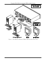
1
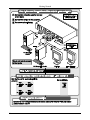
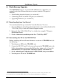
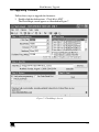
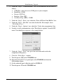
Kramer Electronics, Ltd.
USER MANUAL
Model:
VP-411DS
4x1 Automatic UXGA / Audio Switcher
Contents
Contents
1
2
2.1
3
4
4.1
5
5.1
5.2
5.3
5.4
6
6.1
6.2
6.3
7
8
9
Introduction
Getting Started
Quick Start
Overview
Your VP-411DS 4x1 Automatic UXGA / Audio Switcher
Using the IR Transmitter
Using the VP-411DS 4x1 Automatic UXGA / Audio Switcher
Connecting the VP-411DS 4x1 Automatic UXGA / Audio Switcher
Setting the PRIORITY Dipswitches
Connecting the REMOTE Connector
Connecting a PC
Flash Memory Upgrade
Downloading from the Internet
Connecting the PC to the RS-232 Port
Upgrading Firmware
Technical Specifications
Table of Hex Codes for Serial Communication
Kramer Protocol 2000
1
1
1
3
5
6
7
7
9
10
11
12
12
12
13
15
15
16
Figures
Figure 1: VP-411DS 4x1 Automatic UXGA / Audio Switcher
Figure 2: VP-411DS 4x1 Automatic UXGA / Audio Switcher Underside
Figure 3: VP-411DS 4x1 Automatic UXGA / Audio Switcher Connections
Figure 4: VP-411DS Dipswitches
Figure 5: Connecting the Contact Closure Remote Control PINs
Figure 6: Connecting the PC
Figure 7: Flash Magic Screen
5
6
8
9
10
11
13
Tables
Table 1: VP-411DS 4x1 Automatic UXGA / Audio Switcher Topside Features
Table 2: VP-411DS 4x1 Automatic UXGA / Audio Switcher Underside Features
Table 3: Dipswitch Priority Setup
Table 4: Technical Specifications of the VP-411DS
Table 5: VP-411DS Hex Codes for Switching via RS-232
Table 6: Protocol Definitions
Table 7: Instruction Codes for Protocol 2000
5
6
9
15
15
16
17
i
Introduction
1
Introduction
Welcome to Kramer Electronics! Since 1981, Kramer Electronics has been
providing a world of unique, creative, and affordable solutions to the vast range
of problems that confront the video, audio, presentation, and broadcasting
professional on a daily basis. In recent years, we have redesigned and upgraded
most of our line, making the best even better! Our 1,000-plus different models
now appear in 11 groups1 that are clearly defined by function.
Congratulations on purchasing your Kramer Tools VP-411DS 4x1 Automatic
UXGA / Audio Switcher. This product is ideal for any system requiring
automatic computer and presentation UXGA routing.
The package includes the following items:
VP-411DS 4x1 Automatic UXGA / Audio Switcher
Power adapter (12V DC Input)
This user manual2
2
Getting Started
We recommend that you:
Unpack the equipment carefully and save the original box and packaging
materials for possible future shipment
Review the contents of this user manual
Use Kramer high performance high resolution cables3
2.1 Quick Start
This quick start chart summarizes the basic setup and operation steps.
1 GROUP 1: Distribution Amplifiers; GROUP 2: Switchers and Matrix Switchers; GROUP 3: Control Systems; GROUP 4:
Format/Standards Converters; GROUP 5: Twisted-Pair Solutions; GROUP 6: Specialty AV Products; GROUP 7: Scan
Converters and Scalers; GROUP 8: Cables and Connectors; GROUP 9: Room Connectivity; GROUP 10: Accessories and
Rack Adapters; GROUP 11: Sierra Products
2 Download up-to-date Kramer user manuals from the Internet at this URL: http://www.kramerelectronics.com
3 The complete list of Kramer cables is on our Web site at http://www.kramerelectronics.com
1
Getting Started
2
KRAMER: SIMPLE CREATIVE TECHNOLOGY
Overview
3
Overview
The Kramer VP-411DS is a high performance 4x1 automatic switcher for
UXGA signals and stereo audio signals. It switches any one of four UXGA
sources to the UXGA output 15-pin HD computer graphics video connector,
and any one of four stereo audio sources to the stereo audio output on a 3.5mm
mini jack. Both the UXGA and audio IN 1 connectors are connected to output
loop connectors.
The VP-411DS can be configured to operate in the automatic standby
switching mode or in the manual mode, via the dipswitches. When in the
automatic mode, the VP-411DS will switch to the primary input when it is
present. It will switch to the second input in priority upon loss of the primary
input1 and it will switch from the secondary input back to the primary input
when the primary signal is reconnected. When in the manual mode, the
VP-411DS is controlled by the control panel.
In addition, the VP-411DS:
With its video bandwidth exceeding 300MHz, ensures transparent operation
at the highest resolutions
Includes the Kramer innovative integrated sync processing: KR - ISP™
technology, which lets you achieve a sharp, stable image when the sync
level is too low, by restoring the sync signal waveform
Has PANEL LOCK and OFF buttons
Automatically switches the stereo audio signal with the video signal (audiofollow-video) when switching the active input to the output
Includes PRIORITY dipswitches for selecting the default UXGA master
source signal
Comes with contact closure remote control for forced operation
Is housed in a desktop-sized enclosure, and is 12VDC fed
The VP-411DS can be controlled via the:
Front panel buttons
Infra-red remote control transmitter or infra-red remote extension cable
transmitter
RS-232 serial commands transmitted by a touch screen system, PC, or other
serial controller
Remote control contact closure
1 And down to the input of the lowest priority
3
Overview
To achieve the best performance:
Connect only good quality connection cables, thus avoiding interference,
deterioration in signal quality due to poor matching, and elevated noise
levels (often associated with low quality cables)
Avoid interference from neighboring electrical appliances that may
adversely influence signal quality and position your Kramer VP-411DS
away from moisture, excessive sunlight and dust
Caution – No operator-serviceable parts inside unit.
Warning – Use only the Kramer Electronics input power
wall adapter that is provided with this unit1.
Warning – Disconnect power and unplug unit from wall
before installing or removing device or servicing unit.
1 For example: model number AD2512C, part number 2535-000251
4
KRAMER: SIMPLE CREATIVE TECHNOLOGY
Your VP-411DS 4x1 Automatic UXGA / Audio Switcher
4
Your VP-411DS 4x1 Automatic UXGA / Audio Switcher
Figure 1 and Table 1 define the VP-411DS:
Figure 1: VP-411DS 4x1 Automatic UXGA / Audio Switcher
Table 1: VP-411DS 4x1 Automatic UXGA / Audio Switcher Topside Features
#
1
Feature
IR Receiver
2
3
4
5
6
7
8
9
10
11
12
13
14
15
POWER Switch
OFF Button
INPUT SELECTOR Buttons
PANEL LOCK Button
IN 1 3.5mm Mini Jack
OUTPUT 3.5mm Mini Jack
IN 1 LOOP 3.5mm Mini Jack
IN 1 15-pin HD Connector
OUTPUT 15-pin HD Connector
IN 1 LOOP 15-pin HD Connector
RS-232 9-pin D-sub Port
REMOTE Terminal Block
Connectors
PRIORITY AUTO Dipswitches
REMOTE IR 3.5mm Mini Jack
16
12V DC
Function
The red LED lights when receiving signals from the Infra-red remote
control transmitter
Illuminated switch for turning the unit ON or OFF
Press to disconnect the output from the inputs
Press to select an input
Press to toggle disengaging the front panel buttons
Connect to the unbalanced stereo source (from IN 1 to IN 4)
Connect to an unbalanced stereo audio output
Connect input 1 to an additional audio acceptor
Connect to the video source (from IN 1 to IN 4)
Connect to the video acceptor
Connect input 1 to an additional video acceptor
Connects to the PC or the RS-232 Remote Controller
Connect to a contact closure switch
Set the input priority (see section 5.2)
Connect to an external IR receiver unit for controlling the machine via
1
an IR remote controller (instead of using the front panel IR receiver)
+12V DC connector for powering the unit
1 Can be used instead of the front panel (built-in) IR receiver to remotely control the machine
5
Your VP-411DS 4x1 Automatic UXGA / Audio Switcher
Figure 2 and Table 2 define the underside of the VP-411DS:
Figure 2: VP-411DS 4x1 Automatic UXGA / Audio Switcher Underside
Table 2: VP-411DS 4x1 Automatic UXGA / Audio Switcher Underside Features
#
1
2
Feature
PROGRAM / NORMAL
Switch
Vs and Hs Switch
(from 1 to 4)
Function
Set to NORMAL for normal operation (default), or set to PROGRAM to
upgrade to the latest Kramer firmware via RS-232 (see section 6)
Slide the switch to NORMAL for standard sync detection1
Slide the switch to KR-ISP™ for crisp technology
4.1 Using the IR Transmitter
You can use the RC-IR2 IR transmitter to control the machine via the built-in
IR receiver on the front panel or, instead, via an optional external IR receiver2.
The external IR receiver can be located 15 meters away from the machine. This
distance can be extended to up to 60 meters when used with three extension
cables3.
Before using the external IR receiver, be sure to arrange for your Kramer dealer
to insert the internal IR connection cable4 with the 3.5mm connector that fits
into the REMOTE IR opening on the rear panel.
Connect the external IR receiver to the REMOTE IR 3.5mm connector.
1 By default, both switches are set to NORMAL
2 Model: C-A35M/IRR-50
3 Model: C-A35M/A35F-50
4 P/N: 505-70434010-S
6
KRAMER: SIMPLE CREATIVE TECHNOLOGY
Using the VP-411DS 4x1 Automatic UXGA / Audio Switcher
5
Using the VP-411DS 4x1 Automatic UXGA / Audio Switcher
This section describes how to:
Connect the VP-411DS (see section 5.1)
Select the default master source signal (see section 5.2)
Connect the REMOTE connector (see section 5.3)
Connect a PC (see section 5.4)
5.1 Connecting the VP-411DS 4x1 Automatic UXGA / Audio Switcher
To connect your VP-411DS, as illustrated in the example in Figure 3, do the
following1:
1. Connect up to four2 UXGA/AUDIO sources (for example, PC graphic cards) to
the UXGA IN 15-pin HD connectors and to the AUDIO IN 3.5mm mini plug
connector3.
2. Connect the UXGA OUTPUT 15-pin HD connector and the AUDIO OUTPUT
3.5mm mini plug connector to the acceptor3 (for example, a display and
speakers).
3. If required, connect a local display to the UXGA IN 1 LOOP 15-pin HD
connector.
4. Set the PRIORITY dipswitches (see section 5.2).
5. If required, connect:
The contact closure remote control PINS (see section 5.3)
PC and/or controller to the RS-232 port (see section 5.4)
6. Connect the 12V DC power adapter to the power socket and connect the adapter
to the mains electricity.
1 Switch OFF the power on each device before connecting it to your VP-411DS. After connecting your VP-411DS, switch on
its power and then switch on the power on each device
2 You do not have to connect all the inputs
3 Audio connections are not shown in Figure 3
7
Using the VP-411DS 4x1 Automatic UXGA / Audio Switcher
Figure 3: VP-411DS 4x1 Automatic UXGA / Audio Switcher Connections
8
KRAMER: SIMPLE CREATIVE TECHNOLOGY
Using the VP-411DS 4x1 Automatic UXGA / Audio Switcher
5.2 Setting the PRIORITY Dipswitches
Figure 4 and Table 3 describe the VP-411DS unit dipswitches and the priority
setup, respectively.
Figure 4: VP-411DS Dipswitches
Table 3: Dipswitch Priority Setup
Dip Position
Priority sequence
1
2
3
4
Manual operation
OFF
OFF
OFF
OFF
1, 2, 3, 4
ON
OFF
OFF
OFF
2, 3, 4, 1
OFF
ON
OFF
OFF
3, 4, 1, 2
OFF
OFF
ON
OFF
4, 1, 2, 3
OFF
OFF
OFF
ON
When all the dipswitches are set to OFF, switching is manual and the inputs are
switched to the output via the front panel INPUT SELECTOR buttons.
The priority is always set from the lowest number to the highest. For example,
if input 2 is set to be the primary input (DIP 2 is set to ON and DIPs 1, 3 and 4
are set to OFF), the secondary input is IN 3. IN 4 is the third in the sequence,
and IN 1 will be last in priority. In this case, if the signal on IN 2 is cut off, the
switcher automatically switches IN 3 to the output, and if that is also
disconnected, IN 4 is automatically switched to the output (followed by IN 1, if
necessary). If, in the meantime, the IN 2 signal is restored, IN 2 will take
priority once again.
9
Using the VP-411DS 4x1 Automatic UXGA / Audio Switcher
5.3 Connecting the REMOTE Connector
The contact closure remote control pins operate in a similar way to the Input
selector button. Using the contact closure remote control you can select the
UXGA input or cut off the inputs. To do so, temporarily connect the required
input1 pin on the REMOTE terminal block connector to the GND (Ground) pin,
as Figure 5 illustrates.
DO NOT connect more than one PIN to the GND PIN at the same time
To select IN 1,
connect the 1 PIN
to the G PIN
To select IN 2,
connect the 2 PIN
to the G PIN
To select IN 3,
connect the 3 PIN
to the G PIN
To select IN 4,
connect the 4 PIN
to the G PIN
To select OFF,
connect the OFF
PIN to the G PIN
Figure 5: Connecting the Contact Closure Remote Control PINs
1 IN1, IN 2, IN 3 IN 4, or OFF
10
KRAMER: SIMPLE CREATIVE TECHNOLOGY
Using the VP-411DS 4x1 Automatic UXGA / Audio Switcher
5.4 Connecting a PC
You can connect a PC (or other controller) to the VP-411DS via the RS-232
port for remote control, and for upgrading the firmware.
To connect a PC to a VP-411DS unit, using the Null-modem adapter provided
with the machine (recommended):
Connect the RS-232 9-pin D-sub rear panel port on the VP-411DS unit to
the Null-modem adapter and connect the Null-modem adapter with a 9-wire
flat cable to the RS-232 9-pin D-sub port on your PC
To connect a PC to a VP-411DS unit, without using a Null-modem adapter:
Connect the RS-232 9-pin D-sub port on your PC to the RS-232 9-pin
D-sub rear panel port on the VP-411DS unit, forming a cross-connection1,
as Figure 6 illustrates
PIN 5 Connected to PIN 5 (Ground)
PIN 3 Connected to PIN 2
PIN 2 Connected to PIN 3
9-pin D-sub
(From PC)
9-pin D-sub
(To Switcher)
If a shielded cable is used, connect the shield to PIN 5
Figure 6: Connecting the PC
1 Also known as a Null-modem connection
11
Flash Memory Upgrade
6
Flash Memory Upgrade
The VP-411DS firmware is located in FLASH memory, which lets you
upgrade to the latest Kramer firmware version in minutes! The process
involves:
Downloading from the Internet (see section 6.1)
Connecting the PC to the RS-232 port (see section 6.2)
Upgrading Firmware (see section 6.3)
6.1 Downloading from the Internet
You can download the up-to-date file1 from the Internet. To do so:
1. Go to our Web site at http://www.kramerelectronics.com and download the file:
“VP-411DS_XX.zip” from the Technical Support section.
2. Extract the file: “VP-411DS_XX.zip” to a folder (for example, C:\Program
Files\Kramer Flash).
3. Create a shortcut on your desktop to the file: “Flash Magic.EXE”2.
6.2 Connecting the PC to the RS-232 Port
Before installing the latest Kramer firmware version on a VP-411DS unit, do
the following:
1. Turn the power OFF on the VP-411DS unit.
2. Connect the RS-232 9-pin D-sub rear panel port on the VP-411DS unit to the
Null-modem adapter and connect the Null-modem adapter with a 9-wire flat
cable to the RS-232 9-pin D-sub COM port on your PC (see section 5.4).
3. On the underside panel, slide the switch to PROGRAM, using a screwdriver.
4. Turn the power ON on the VP-411DS unit.
1 The files indicated in this section are given as an example only. File names are liable to change from time to time
2 To download the up-to-date Flash Magic software, go to the http://www.flashmagictool.com/ Web site
12
KRAMER: SIMPLE CREATIVE TECHNOLOGY
Flash Memory Upgrade
6.3 Upgrading Firmware
Follow these steps to upgrade the firmware:
1. Double click the desktop icon: “Flash Magic.EXE”.
The Flash Magic screen appears as illustrated in Figure 7.
Figure 7: Flash Magic Screen
13
Flash Memory Upgrade
2. Under the “Step 1 – Communications” area, set the definitions on the screen as
follows:
COM Port: select the active COM port on your computer
Baud Rate: 19200
Device: LPC2368
Interface: None (ISP)
Oscillator Freq. (MHz): 12.000
3. Under the “Step 2 – Erase” area, check the “Erase all Flash+Code Rd Prot” box.
4. Under the “Step 3 – Hex File” area select the hex file. For example, select
“VP-411DS_12.hex”.
5. Under the “Step 4 – Options” area, check the “Verify after programming” box.
6. In order to verify communication, select "Read device signature" from the ISP
menu. You should get a response as the example below:
7. Under the “Step 5 – Start!” area, press the start button and wait for the
completion of the process.
8. Close the “Flash Magic” window.
9. Turn the power OFF on the VP-411DS unit.
10. Disconnect the RS-232 rear panel port on the VP-411DS unit from the
Null-modem adapter.
11. On the underside panel, slide the switch to NORMAL.
12. Turn the power ON on the VP-411DS unit.
14
KRAMER: SIMPLE CREATIVE TECHNOLOGY
Technical Specifications
7
Technical Specifications
Table 4 includes the technical specifications:
1
Table 4: Technical Specifications of the VP-411DS
INPUTS:
4 UXGA on 15-pin HD connectors
4 unbalanced stereo audio on 3.5mm mini audio connectors
OUTPUTS:
1 UXGA on a 15-pin HD connector
1 UXGA on a 15-pin HD connector (IN 1 LOOP)
2 unbalanced stereo audio on a 3.5mm mini audio connector
MAX. OUTPUT LEVEL:
VIDEO: 1.8Vpp
AUDIO: 7.2Vpp
BANDWIDTH (-3dB):
VIDEO: 300MHz
AUDIO: >40kHz
DIFF. GAIN:
0.03%
DIFF. PHASE:
0.06 Deg
K-FACTOR:
<0.05%
S/N RATIO:
VIDEO:73dB @ 5MHz
AUDIO: 93dB
CROSSTALK (all hostile):
VIDEO: –50dB
AUDIO: –72dB @ 1kHz
CONTROLS:
Input selector; PANEL LOCK and OFF pushbuttons; IR remote control
reception window; connector for extended IR reception;
RS-232 connector; contact closure terminal block for external wire
switching; inputs priority selector dipswitches; normal/KR-ISP™ and
program/normal mode selectors via slide switches on the underside.
COUPLING:
VIDEO: DC
AUDIO THD + NOISE:
0.004% @1kHZ
AUDIO: DC
AUDIO 2nd HARMONIC:
0.002% @1kHZ
POWER SOURCE:
12V, 230mA
DIMENSIONS:
21.5cm x 16.25cm x 4.36cm (8.46” x 6.4” x 1.7”) W, D, H
WEIGHT:
ACCESSORIES:
1.1kg (2.43lb) approx.
Power supply, IR remote control
OPTIONS:
rack adapter
8
Table of Hex Codes for Serial Communication
Table 5 lists the Hex values:
Table 5: VP-411DS Hex Codes for Switching via RS-232
IN 1
OUT 1
, ,
,
IN 2
,
,
,
IN 3
,
,
,
IN 4
,
,
,
1 Specifications are subject to change without notice
15
Kramer Protocol 2000
9
Kramer Protocol 20001
The VP-411DS is compatible with Kramer’s Protocol 2000 (version 0.50)
(below). This RS-232/RS-485 communication protocol uses four bytes of
information as defined below. For RS-232, a null-modem connection between
the machine and controller is used. The default data rate is 9600 baud, with no
parity, 8 data bits and 1 stop bit.
Note: compatible with Kramer’s Protocol 2000 does not imply that a machine
includes all of the commands below. Each machine uses a sub-set of Protocol
2000, according to its needs.
Table 6: Protocol Definitions
MSB
LSB
DESTINATION
0
7
D
6
INSTRUCTION
N5
5
N4
4
N3
3
N2
2
N1
1
N0
0
I5
5
I4
4
I3
3
I2
2
I1
1
I0
0
O6
6
O5
5
O4
4
O3
3
O2
2
O1
1
O0
0
OVR
6
X
5
M2
2
M1
1
M0
0
1st byte
INPUT
1
7
I6
6
2nd byte
OUTPUT
1
7
3rd byte
MACHINE NUMBER
1
7
4th byte
M4
4
M3
3
Bit 7 – Defined as 0.
1st BYTE:
D – “ DESTINATION” :
0 - for sending information to the switchers (from the PC);
1 - for sending to the PC (from the switcher).
N5…N0 – “ INSTRUCTION”
The function that is to be performed by the switcher(s) is defined by the INSTRUCTION (6 bits). Similarly, if a function is
performed via the machine’s keyboard, then these bits are set with the INSTRUCTION NO., which was performed. The
instruction codes are defined according to the table below (INSTRUCTION NO. is the value to be set for N5…N0).
2nd BYTE:
Bit 7 – Defined as 1.
I6…I0 – “ INPUT” .
When switching (ie. instruction codes 1 and 2), the INPUT (7 bits) is set as the input number which is to be switched.
Similarly, if switching is done via the machine’s front-panel, then these bits are set with the INPUT NUMBER which was
switched. For other operations, these bits are defined according to the table.
3rd BYTE:
Bit 7 – Defined as 1.
O6…O0 – “ OUTPUT” .
When switching (ie. instruction codes 1 and 2), the OUTPUT (7 bits) is set as the output number which is to be switched.
Similarly, if switching is done via the machine’s front-panel, then these bits are set with the OUTPUT NUMBER which was
switched. For other operations, these bits are defined according to the table.
1 You can download our user-friendly “ Software for Calculating Hex Codes for Protocol 2000” from the technical support
section on our Web site at: http://www.kramerelectronics.com
16
KRAMER: SIMPLE CREATIVE TECHNOLOGY
Kramer Protocol 2000
4th BYTE:
Bit 7 – Defined as 1.
Bit 5 – Don’t care.
OVR – Machine number override.
M4…M0 – MACHINE NUMBER.
Used to address machines in a system via their machine numbers. When several machines are controlled from a single serial
port, they are usually configured together with each machine having an individual machine number. If the OVR bit is set, then
all machine numbers will accept (implement) the command, and the addressed machine will reply.
For a single machine controlled via the serial port, always set M4…M0 = 1, and make sure that the machine itself is
configured as MACHINE NUMBER = 1.
Table 7: Instruction Codes for Protocol 2000
Note: All values in the table are decimal, unless otherwise stated.
INSTRUCTION
DEFINITION FOR SPECIFIC INSTRUCTION
#
DESCRIPTION
INPUT
0
1
RESET
SWITCH INPUT
5
16
REQUEST STATUS OF A
VIDEO OUTPUT
ERROR / BUSY
30
LOCK FRONT PANEL
31
61
REQUEST WHETHER
PANEL IS LOCKED
IDENTIFY MACHINE
62
DEFINE MACHINE
0
Set equal to video input
which is to be switched
(0 = disconnect)
0
0
Panel unlocked
Panel locked
0
video machine name
video software version
number of inputs
number of outputs
NOTE
OUTPUT
0
1
1
2
Equal to output number
whose status is reqd
error
invalid instruction
out of range
machine busy
RX buffer overflow
0
3
0
7
Request first 4 digits
Request first suffix
for video
for audio
4
2
5
6
NOTES on the above table:
NOTE 1 - When the master switcher is reset, (e.g. when it is turned on), the reset code is sent to the PC. If this code is sent to
the switchers, it will reset according to the present power-down settings.
NOTE 2 - These are bi-directional definitions. That is, if the switcher receives the code, it will perform the instruction; and if
the instruction is performed (due to a keystroke operation on the front panel), then these codes are sent. For example, if the
HEX code
01
85
88
83
was sent from the PC, then the switcher (machine 3) will switch input 5 to output 8. If the user switched input 1 to output 7
via the front panel keypad, then the switcher will send HEX codes:
41
81
87
83
to the PC.
When the PC sends one of the commands in this group to the switcher, then, if the instruction is valid, the switcher replies by
sending to the PC the same four bytes that it was sent (except for the first byte, where the DESTINATION bit is set high).
NOTE 3 - The reply to a "REQUEST" instruction is as follows: the same instruction and INPUT codes as were sent are
returned, and the OUTPUT is assigned the value of the requested parameter. The replies to instructions 10 and 11 are as per
the definitions in instructions 7 and 8 respectively. For example, if the present status of machine number 5 is breakaway
setting, then the reply to the HEX code
0B
80
80
85
81
85
would be HEX codes
4B
80
NOTE 4 - An error code is returned to the PC if an invalid instruction code was sent to the switcher, or if a parameter
associated with the instruction is out of range (e.g. trying to save to a setup greater than the highest one, or trying to switch an
input or output greater than the highest one defined). This code is also returned to the PC if an RS-232 instruction is sent
while the machine is being programmed via the front panel. Reception of this code by the switcher is not valid.
17
Kramer Protocol 2000
NOTE 5 - This is a request to identify the switcher/s in the system. If the OUTPUT is set as 0, and the INPUT is set as 1 the
machine will send its name. The reply is the decimal value of the INPUT and OUTPUT. For example, for a 2216, the reply to
the request to send the audio machine name would be (HEX codes):
7D
96
90
81 (i.e. 128dec+ 22dec for 2nd byte, and 128dec+ 16dec for 3rd byte).
If the request for identification is sent with the INPUT set as 3 the appropriate machine will send its software version number.
Again, the reply would be the decimal value of the INPUT and OUTPUT - the INPUT representing the number in front of the
decimal point, and the OUTPUT representing the number after it. For example, for version 3.5, the reply to the request to send
the version number would be (HEX codes):
7D
83
85
81 (i.e. 128dec+ 3dec for 2nd byte, 128dec+ 5dec for 3rd byte).
If the OUTPUT is set as 1, then the ASCII coding of the lettering following the machine’s name is sent. For example, for the
VS-7588YC, the reply to the request to send the first suffix would be (HEX codes):
7D
D9
C3
81 (i.e. 128dec+ ASCII for “ Y” ; 128dec+ ASCII for “ C” ).
NOTE 6 - The number of inputs and outputs refers to the specific machine which is being addressed, not to the system. For
example, if six 16X16 matrices are configured to make a 48X32 system (48 inputs, 32 outputs), the reply to the HEX code
3E
82
81
82 (ie. request the number of outputs)
90
82
would be HEX codes
7E
82
ie. 16 outputs
NOTE 7 - The reply to the “ REQUEST WHETHER PANEL IS LOCKED” is as in NOTE 3 above, except that here the
OUTPUT is assigned with the value 0 if the panel is unlocked, or 1 if it is locked.
18
KRAMER: SIMPLE CREATIVE TECHNOLOGY
LIMITED WARRANTY
Kramer Electronics (hereafter Kramer) warrants this product free from defects in material and workmanship under the
following terms.
HOW LONG IS THE WARRANTY
Labor and parts are warranted for seven years from the date of the first customer purchase.
WHO IS PROTECTED?
Only the first purchase customer may enforce this warranty.
WHAT IS COVERED AND WHAT IS NOT COVERED
Except as below, this warranty covers all defects in material or workmanship in this product. The following are not covered
by the warranty:
1. Any product which is not distributed by Kramer, or which is not purchased from an authorized Kramer dealer. If you are
uncertain as to whether a dealer is authorized, please contact Kramer at one of the agents listed in the Web site
www.kramerelectronics.com.
2. Any product, on which the serial number has been defaced, modified or removed, or on which the WARRANTY VOID
IF TAMPERED sticker has been torn, reattached, removed or otherwise interfered with.
3. Damage, deterioration or malfunction resulting from:
i) Accident, misuse, abuse, neglect, fire, water, lightning or other acts of nature
ii) Product modification, or failure to follow instructions supplied with the product
iii) Repair or attempted repair by anyone not authorized by Kramer
iv) Any shipment of the product (claims must be presented to the carrier)
v) Removal or installation of the product
vi) Any other cause, which does not relate to a product defect
vii) Cartons, equipment enclosures, cables or accessories used in conjunction with the product
WHAT WE WILL PAY FOR AND WHAT WE WILL NOT PAY FOR
We will pay labor and material expenses for covered items. We will not pay for the following:
1. Removal or installations charges.
2. Costs of initial technical adjustments (set-up), including adjustment of user controls or programming. These costs are the
responsibility of the Kramer dealer from whom the product was purchased.
3. Shipping charges.
HOW YOU CAN GET WARRANTY SERVICE
1. To obtain service on you product, you must take or ship it prepaid to any authorized Kramer service center.
2. Whenever warranty service is required, the original dated invoice (or a copy) must be presented as proof of warranty
coverage, and should be included in any shipment of the product. Please also include in any mailing a contact name,
company, address, and a description of the problem(s).
3. For the name of the nearest Kramer authorized service center, consult your authorized dealer.
LIMITATION OF IMPLIED WARRANTIES
All implied warranties, including warranties of merchantability and fitness for a particular purpose, are limited in duration to
the length of this warranty.
EXCLUSION OF DAMAGES
The liability of Kramer for any effective products is limited to the repair or replacement of the product at our option. Kramer shall
not be liable for:
1. Damage to other property caused by defects in this product, damages based upon inconvenience, loss of use of the product, loss
of time, commercial loss; or:
2. Any other damages, whether incidental, consequential or otherwise. Some countries may not allow limitations on how long an
implied warranty lasts and/or do not allow the exclusion or limitation of incidental or consequential damages, so the above
limitations and exclusions may not apply to you.
This warranty gives you specific legal rights, and you may also have other rights, which vary from place to place.
NOTE: All products returned to Kramer for service must have prior approval. This may be obtained from your dealer.
This equipment has been tested to determine compliance with the requirements of:
EN-50081:
EN-50082:
CFR-47:
"Electromagnetic compatibility (EMC);
generic emission standard.
Part 1: Residential, commercial and light industry"
"Electromagnetic compatibility (EMC) generic immunity standard.
Part 1: Residential, commercial and light industry environment".
FCC Rules and Regulations:
Part 15: “ Radio frequency devices
Subpart B Unintentional radiators”
CAUTION!
Servicing the machines can only be done by an authorized Kramer technician. Any user who makes changes or
modifications to the unit without the expressed approval of the manufacturer will void user authority to operate the
equipment.
Use the supplied DC power supply to feed power to the machine.
Please use recommended interconnection cables to connect the machine to other components.
19
For the latest information on our products and a list of Kramer
distributors, visit our Web site: www.kramerelectronics.com,
where updates to this user manual may be found.
We welcome your questions, comments and feedback.
Safety Warning:
Disconnect the unit from the power supply before
opening/servicing.
Caution
Kramer Electronics, Ltd.
Web site: www.kramerelectronics.com
E-mail: [email protected]
P/N: 2900-000377 REV 2