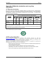
1
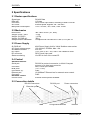
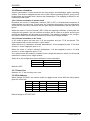
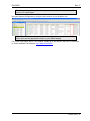
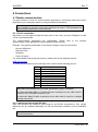
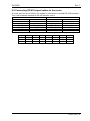
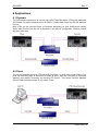
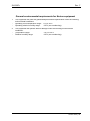
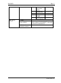
SL-D32P+ Expandable Ported RS-422 Data Router User manual Rev. E Nevion Nordre Kullerød 1 3241 Sandefjord Norway Tel: +47 33 48 99 99 nevion.com SL-D32P+ Rev. F Nevion Support Nevion Europe Nevion USA P.O. Box 1020 3204 Sandefjord, Norway Support phone 1: +47 33 48 99 97 Support phone 2: +47 90 60 99 99 1600 Emerson Avenue Oxnard, CA 93033, USA Toll free North America: (866) 515-0811 Outside North America: +1 (805) 247-8560 E-mail: [email protected] See http://www.nevion.com/support/ for service hours for customer support globally. Revision history Current revision of this document is the uppermost in the table below. Rev. Repl. Date Sign Change description F E 2013-07-18 JGS E 4 3 4 3 2 2013-06-11 2012-02-21 2011-10-05 JGS AAA NBS 2 1 1 0 2011-03-29 2011-03-23 NBS NBS 0 - 2011-01-25 NBS Updated chapter 4.1.2 with supported network modes. Corrected data rate specification Added comment for the MRP protocol option Corrected LED status Moved signal connection to new Chapter Added Appendix B. Added Grass Valley Native Protocol in Chapter 0 and Appendix B.2. Updated Chapter 0 (Configuring protocol options). Added Extension cable specs. Corrected housing and gender spec on D-sub 9-pin contacts. First release. nevion.com | 2 SL-D32P+ Rev. F Contents Revision history ........................................................................................................ 2 1 Product overview ................................................................................................... 5 1.1 Product versions ........................................................................................................... 5 2 Specifications ........................................................................................................ 6 2.1 Router specifications ..................................................................................................... 6 2.2 Mechanics ..................................................................................................................... 6 2.3 Power Supply ................................................................................................................ 6 2.4 Control .......................................................................................................................... 6 2.5 Connection details......................................................................................................... 6 2.5.1 Power Supply pin-out ................................................................................................. 7 3 Configuration ......................................................................................................... 8 3.1 Nevion Configurator ...................................................................................................... 8 3.2 Configuration switches .................................................................................................. 9 3.2.1 Router level ................................................................................................................ 9 3.2.2 Audio/Video Mode ...................................................................................................... 9 3.2.3 XY Mode ...................................................................................................................10 3.2.4 Power alarm ..............................................................................................................10 3.2.5 Power up mode .........................................................................................................10 3.2.6 Router orientation ......................................................................................................11 3.2.7 Future Use ................................................................................................................11 3.2.8 Ext Address ...............................................................................................................11 3.3 Configuring protocol options .........................................................................................12 4 Connections ........................................................................................................ 14 4.1 Router communication .................................................................................................14 4.1.1 Serial connection .......................................................................................................14 4.1.2 Ethernet connection ..................................................................................................15 4.1.3 NCB connection ........................................................................................................16 4.1.4 Router extension .......................................................................................................17 4.2 Connecting RS-422 signal cables to the router.............................................................19 5 LED status ........................................................................................................... 20 5.1 Start-up ........................................................................................................................20 5.2 Alarm states .................................................................................................................20 5.3 Ethernet states .............................................................................................................20 6 Applications ......................................................................................................... 21 6.1 Dynamic .......................................................................................................................21 6.2 Fixed ............................................................................................................................21 General environmental requirements for Nevion equipment .................................. 22 Product Warranty.................................................................................................... 23 Important notes regarding Software in the VikinX Modular router family range ...... 24 Appendix A Materials declaration and recycling information .................................. 25 A.1 Materials declaration ....................................................................................................25 A.2 Recycling information...................................................................................................25 Appendix B Additional Protocol information ............................................................ 26 nevion.com | 3 SL-D32P+ Rev. F B.1 Leitch Pass-Through protocol ......................................................................................26 B.2 Grass Valley Native protocol ........................................................................................26 nevion.com | 4 SL-D32P+ Rev. F 1 Product overview Professional broadcast installations often include a number of tape recorders and other devices that require RS-422 machine control for remote operation. To meet these requirements, Nevion introduce the Sublime SL-D32P+ Expandable Ported Data Router. Complex installations, cable cost and system design is kept at a minimum. Where user friendliness and operational flexibility is appreciated, the SL-D32P+ will fit in perfectly. The Ported Data Routers are bi-directional “ports” rather than “XY”. A traditional 32x32 router will have a total of 64 connectors (32 in/32 out). A ported 32 Router will have a maximum of 32 connectors, all configurable to be operated either as Controller or Device. In the SL-D32P+ Ported Data Router the terms Controller and Device are used instead of In/Out, Source/Destination. I.e. a Ported Data Router Controller can be both signal Source or Destination. SL-D32P+ can be bundled together to for 64/96/128 ports. All ports are coupled according to SMPTE 207M machine control standard. 1.1 Product versions The following versions of the VikinX Sublime SL-D32P+ router are available: SL-D32P+ SL-D64P+ SL-D96P+ SL-D128P 32 Port RS-422 Data Router. Expandable up to 128 ports. Ethernet/RS-232/NCB control, configurable data ports, SMPTE 207M compliant , 19" 2RU depth 5cm. 64 Port RS-422 Data Router. Expandable up to 128 ports. Bundle of 2x SL-D32P+ , 19" 4RU depth 5cm. 96 Port RS-422 Data Router. Expandable up to 128 ports. Bundle of 3x SL-D32P+ , 19" 6RU depth 5cm. 128 Port RS-422 Data Router. Bundle of 4x SL-D32P+ , 19" 8RU depth 5cm. nevion.com | 5 SL-D32P+ Rev. F 2 Specifications 2.1 Router specifications Signal type: Data rate: Connector: AC Power: Max power consumption: RS-422 Data 115 kbps DE9, D-sub 9-pin female, according to SMPTE 207M External power supplies 100 - 260 VAC +15V / 675mA; -15V / 0mA; Total: 10.2W 2.2 Mechanics Dimensions: Weight, router + PSU: Weight, SL-D32P+: Weight, SL-PWR-40: Safety/Emission standards: 483 x 88 x 45 mm (19”, 2RU). 1.5 kg. 1.15 kg 350 g Compliant with CE EN55103-1 and 2, FCC part 15. 2.3 Power Supply SL-PWR-40 AC Supply voltage range: AC Mains connector: DC output: DC connector: Status monitoring: 40W Power Supply Unit for VikinX Sublime router series. 100-240VAC, 50-60Hz, Max 1.6A. IEC 320. +15V, max. 2.2A / -15V, max 1.35A. Maximum 43W. DE9, D-sub 9-pin male. Via LED in front of the router/CP. 2.4 Control Standard features: Serial port: RS-232 for protocol conversion; to VikinX Compact protocol, or to third party protocols. DE9, D-sub 9-pin female. (1 In / 1 Out). RJ45. 10/100BaseT Ethernet bus for external router control. RJ45. Connector: NCB ports: Connectors (2): Ethernet port: Connector: Hardware control: Control Panel: External control panels available. 2.5 Connection details RS-422 Connectors RS-232 port Power connectors Extension ports NCB Configuration switches Ethernet nevion.com | 6 SL-D32P+ Rev. F The following connectors and switches can be found on the rear of the SL-D32P+: RS-422: RS-232 Port: Power A: Power B: NCB IN: NCB OUT: Configuration: Ethernet: EXT IN: EXT OUT: 32 device connectors. RS-232 for external control. ±15VDC Power Input. ±15VDC Power Input, redundant supply. Network Control Bus Input. Network Control Bus Output. Dip switches for configuration settings. 10/100 Base-T Ethernet bus for external router control. Router extension loop Input. Router extension loop Output. 2.5.1 Power Supply pin-out The DE9 male sockets for the power connection on Sublime routers and Control Panels have the following pin-out; Pin # 1 2 3 4 5 6 7 8 9 Description GND Not connected Not connected +15VDC Not connected Not connected Not connected -15VDC Not connected nevion.com | 7 SL-D32P+ Rev. F 3 Configuration It is possible to use the router out-of-the-box. Changes to the factory settings can be set with the dip-switches found in the back of the router. As factory setting, the SL-D32P+ is shipped with Dynamic ports. This means every port can be controller or device depending on the connected equipment. Full access to the Sublime SL-D32P+ Ported Data Router configuration is achieved with the Nevion Configurator in combination with the dip-switches. 3.1 Nevion Configurator The Nevion Configurator is a unified configuration tool for routers interconnected over Ethernet. The Nevion Configurator makes system set-up easy and includes a wizard to guide you through the set-up procedures. When scanning the network, the Nevion Configurator auto detects all connected hardware. It also provides interactive help, giving Auto Feedback on non-logical settings. For more information about the Nevion Configurator and its advanced configuration possibilities, please use the interactive help menus included in the software. Dynamic: The Controller/Device is according to the connected units itself. Fixed: The Port can be set to either be Controller (Master) or Device (Slave). nevion.com | 8 SL-D32P+ Rev. F 3.2 Configuration switches You will find 2 x 10 Dip-switches on the backplane of the router. These are for configuration purposes. 3.2.1 Router level Switches 1 - 4 set the router level and the Physical Address for this unit. By setting routers and Control Panels on same level, routers can be controlled as “one”, i.e. Audio-followVideo. Bundled SL-D32P+ routers (up to 4 units) must have the same address/level setting in order to be operated as one router. For more information on Physical Addresses, see the section for re-Mapping in the Nevion Configurator or the Modular Protocol documentation found on the www.nevion.com. THOR and panels in a NCB loop must be configured to the same level as the router(s). The levels/Physical Addresses can be set according to the following pattern: SW 1 SW 2 OFF OFF OFF OFF OFF OFF OFF OFF OFF ON OFF ON OFF ON OFF ON OFF ON OFF ON OFF ON OFF ON ON ON ON ON ON ON ON ON Default level is 1. SW 3 OFF OFF ON ON OFF OFF ON ON OFF OFF ON ON OFF OFF ON ON SW 4 OFF ON OFF ON OFF ON OFF ON OFF ON OFF ON OFF ON OFF ON Level 1 2 3 4 5 6 7 8 9 10 11 12 13 14 15 16 Physical Address 0 1 2 3 4 5 6 7 8 9 10 11 12 13 14 15 3.2.2 Audio/Video Mode The SL-D32P+ router can be assigned to either the video level or the audio level of a router system, selectable with switch 5 on the configuration switch. If you’re using the Data Router in an Audio-follow-video setting, the Data Router can be set as Video, giving an Audiofollow-Data function. Breakaway is also possible with this set-up. SW 5 OFF ON Router mode Controlled as Audio Controlled as Video Default mode is OFF. Bundled SL-D32P+ routers (up to 4 units) must have the same mode setting in order to be operated as one router. nevion.com | 9 SL-D32P+ Rev. F 3.2.3 XY Mode If The SL-D32P+ Ported Data Router is to be configured as a D1616, D3232, D4848 or D6464 router, this DIP must be ON. In this mode SL-D32P+ will be identical with the existing VikinX D1616 and D3232 Data Router. SW 6 OFF ON D1616 mode Ported mode XY mode Default mode is OFF. The RS422 ports on the SL-D32P+ are labeled from 1 to 32. When multiple routers are connected together to form a bigger router, the ports are used as the tables below. In ported mode: Ext Address 0 1 2 3 Port 1-32 1-32 1-32 1-32 Combined router port Port 1-32 Port 33-64 Port 65-96 Port 92-128 In XY mode: Ext Address 0 0 1 1 2 2 3 3 Port 1-16 17-32 1-16 17-32 1-16 17-32 1-16 17-32 Destination oriented Source 1-16 Destination 1-16 Source 17-32 Destination 17-32 Source 33-48 Destination 33-48 Source 49-64 Destination 49-64 Source oriented Destination 1-16 Source 1-16 Destination 17-32 Source 17-32 Destination 33-48 Source 33-48 Destination 49-64 Source 49-64 3.2.4 Power alarm When using redundant power supply, the power alarm should be ON. The SL-D32P+ will give alarm, and the front LED will blink red, when one of the power supplies connected fails. If only one power supply is connected, this DIP must be off. SW 7 OFF ON Router orientation Disable Power Alarms Enables Power Alarms Default mode is OFF. 3.2.5 Power up mode Switch 8 on the configuration switch defines the power up mode. The SL-D32P+ router provides two modes for powering up the system. Mode 1 switches all ports are disconnected. Mode 2 switches all ports according to the latest setting buffered in the routers processor system. The power up mode can be switched according to the following pattern: SW 8 OFF ON Power Up mode Mode 2 Mode 1 Default is OFF. nevion.com | 10 SL-D32P+ Rev. F 3.2.6 Router orientation X-point commands in control protocols are using source and destination when controlling routers. This must be mapped to ports in the router. When controlling RS-422, every port is bi-directional and includes both a source and a destination. The mapping is different in XY mode and ported mode. 3.2.6.1 Router orientation in ported mode By default, the router is "destination oriented" (DIP is OFF). A bi-directional connection is made between the two ports. If both ports are configured as dynamic, the port referred as source will be used as a controller and the port referred as destination will be used as a device. When the router is "source oriented" (DIP is ON) the mapping is different. If both ports are configured as dynamic, the port referred as source will be used as a device and the port referred as destination will be used as a controller. This makes it possible to use a singlebus panel to select one-of-several machines to control from a single location. 3.2.6.2 Router orientation in XY mode In XY mode all ports are fixed; port 1-16 as controllers and port 17-32 as devices. The control system will see the router as a 16x16 matrix. When the router is "destination oriented" destinations 1-16 are mapped to ports 17-32 while sources 1-16 are mapped to ports 1-16. When the router is "source oriented" destinations 1-16 are mapped to ports 1-16 while sources 1-16 are mapped to ports 17-32. As in ported mode this makes it possible to use a single-bus panel to select one-of-several machines to control from a single location. Switch 9 on the configuration switch defines the router orientation. SW 9 OFF ON Router orientation Destination oriented Source oriented Default is OFF. 3.2.7 Future Use Switches 10 -17 are currently not in use. 3.2.8 Ext Address When multiple SL-D32P+ are used to make one bigger router, these DIPs are telling which ports this router has. SW 18 OFF OFF OFF OFF SW 19 OFF OFF ON ON SW 20 OFF ON OFF ON Ext Address 0 1 2 3 Ports 1-32 33-64 65-96 92-128 Default setting is OFF/OFF/OFF. nevion.com | 11 SL-D32P+ Rev. F 3.3 Configuring protocol options For various reasons, Nevion has decided to make it possible to turn the extra commands that were added to the NCB protocol when we introduced the Sublime router range either off or on. At the same time, the user must select whether he/she shall use the RS-232 port for controlling the router or the Ethernet port. This is done in order to prevent both ports from simultaneously being applied for controlling the router. There is a new Protocol field in the Nevion Configurator where you may choose from the following options; NCB without Sublime ext. (RS232) This is the “old” Compact NCB protocol, without Sublime extensions. If used on a Sublime, it also disables the Ethernet port of that device. NCB (RS232) This is the regular Sublime protocol, with the extra commands that were added to the NCB protocol. If used on a Sublime, it also disables the Ethernet port of that device. This is the default option for the Sublime range of products. This protocol is similar to the Triton protocol, allowing users to connect the Sublime device to a Jupiter VM 3000 System Controller. MRP (TCP/IP) This option is only applicable to the Sublime range. It selects the Ethernet protocol as the control option, and disables the RS-232 port of that device. Note that the above selection is only possible if you have Sublime FW rel. 2.1.1 or newer installed on your Sublime device, and Nevion Configurator rel. 3.3.5 or newer installed on your PC. It is NOT possible to select protocol options on Sublimes with HW Rev. 1. MRP is always enabled when any TCP/IP based protocol is selected. This makes it possible to use Sublime panels when a third party protocol is selected. Leitch Pass-Through (RS-232) This option allows support for Leitch Pass-Through protocol via RS-232 interface. The details of this protocol are described in Leitch Routing Switchers Serial Protocol Reference, Edition E. See also Appendix B.1 for details. This option is not supported over NCB. Leitch Pass-Through (TCP/IP) This option allows support for Leitch Pass-Through protocol via TCP/IP interface. The details of this protocol are described in Leitch Routing Switchers Serial Protocol Reference, Edition E. The interface is using port 23 for this protocol option; same port as for Telnet applications. See also Appendix B.1 for details. The Leitch Pass-Through selections are only available on Sublime routers with FW version 2.4.x and higher. Grass Valley Native protocol (TCP/IP) This option allows support for Grass Valley Native protocol via TCP/IP interface, using port 12345. The subset of this protocol that is supported by Sublime routers is described in Appendix B.2. nevion.com | 12 SL-D32P+ Rev. F The Grass Valley Native protocol is only available on Sublime routers with FW version 2.5.4 and higher. Use your Nevion Configurator to verify the HW revision of your Sublime unit: Right-click the column headers and select the appropriate column to be shown, if you don’t see the appropriate column in your default display. For further information about FW releases, please go to the Nevion web site to download, or check available FW releases: http://www.nevion.com. nevion.com | 13 SL-D32P+ Rev. F 4 Connections 4.1 Router communication You gain access to router for communication purposes by connecting either the router’s serial port to your computer and/or by using an Ethernet connection. When multiple SL-D32P+ is connected together to make a bigger matrix, it is not necessary to connect to more the one device at a time. The commands are automatically distributed to all the devices. 4.1.1 Serial connection Connection can be made through the serial port of the router; see also Chapters 2.4 and 2.5 for connection details. The communication parameters are configurable. Please refer to the protocol documentation of the appropriate communication/control protocol. Example: The protocol parameters of the VikinX Compact routers are as follows: Bit rate 19200 bit/s Data bits 8 bits Stop bits 1 Parity: No parity For further details concerning this protocol, please refer to the following manual: NCB Protocol.pdf. The DE9 female socket for the serial port of the router has the following pin-out: Pin # 1 2 3 4 5 6 7 8 9 RS-232 mode Not in use Tx Rx Not in use GND GND RTS CTS Do Not Connect! Note that if the standard RS-232 cable specification (DCE) is followed: A cable with Male+Male or Female+Female connectors at the cable ends is used for Rx/Tx crossed connection, and A cable with Male+Female connectors at the cable ends is used for a straight through connection. 4.1.1.1 Maximum cable length (RS-232) IEEE has specified the maximum cable length for an RS-232 connection to 15m. Longer distances can be installed depending on the environmental conditions of the installation site. It is the responsibility of the installer / user to secure a proper installation of the RS-232 connection. nevion.com | 14 SL-D32P+ Rev. F 4.1.2 Ethernet connection The connections follow the standard set by the IEEE 802.3 100BaseTX specification. The cables that are to be applied should be CAT-5 / CAT-5E standard, or better. It is the responsibility of the installer / user to secure a proper installation of the Ethernet connection. A VikinX Sublime device supports the following setups: 100 Mb/s, half duplex (default) 10 Mb/s, half duplex This setup is valid from VikinX Sublime firmware 2.6.3 and newer. Changing the ethernet setup on a VikinX Sublime must be done with the Nevion Configurator, version 4.4.0 or newer. All VikinX Sublime routers and IP-based Control Panels are connected together through an Ethernet Switch. A VikinX Sublime device has only one physical Ethernet connection. If redundant control is required, this limitation has to be solved by the control system. For Ethernet protocol details concerning this router, please refer to the following manual: Modular Router Control Protocol. This manual can be found on our web site: http://www.nevion.com. 4.1.2.1 HW limitations With the introduction of Sublime controller HW Rev. 2, the user has the option of connecting more than two devices together, without having a Multicon to control the network. See Chapter 0 for verification of the HW revision of your device. Unless you apply a Multicon as a system controller, the limitations that apply are: 1. One Sublime control panel may connect to a maximum of 4 Sublime routers. 2. One Sublime router may be controlled by a maximum of 4 Sublime control panels. Exceptions to the above limitations: A router with a local CP (e.g. SL-V6464-CP) may only connect to 1 other router. Both routers must be configured with the same address and be of different type (A+V). Example: 1x SL-V6464-CP may only control itself + 1x Audio router (AA or AES). Both routers must be configured with the same address. 16x2 routers that are expanded to NNx2 are using the NCB bus for this purpose. The total NNx2 router is therefore counted as 1 router in the limitations 1 and 2 above. From limitations 1 and 2 above, the resulting Ethernet configuration may consist of maximum 8 devices; 4 routers and 4 control panels, with the exceptions mentioned above. An example is illustrated in the figure below. nevion.com | 15 SL-D32P+ Rev. F Figure 1: Ethernet connections and configuration. Refer to the Nevion Configurator User Manual for further information about the above described configuration/connection options. It is NOT possible to connect more than 2x Sublimes with HW Rev. 1 together via Ethernet, unless a Multicon is applied as system controller. 4.1.3 NCB connection Via the Network Control Bus system several routers and control panels can be interconnected. Up to 16 levels of routers, or combinations of routers, can be controlled. The NCB system and all RS 232 ports interchange the system status. This means that any control system, either from Nevion, or from a third party manufacturer, connected to any RS 232 port in the NCB loop, will have access to all communication data on the bus. 4.1.3.1 Connecting control panels To get a control panel working with a specific router, configure the control panel to the same level as the router. Several panels can be configured to control the same router. Panels can also be connected to a router via the RS-232 interface. Please refer to your control panel manual for installation. 4.1.3.2 Pin-out and cable type VikinX Sublime routers and Control Panels use RJ45 connectors for the Network Control Bus ports. The following pin-out is used: Pin #1 Not Connected Pin #2 Not Connected Pin #3 Data (retour) Pin #4 Data Pin #5 Data Pin #6 Data (retour) Pin #7 Not Connected Pin #8 Not Connected The following connection example shows connection of 4 VikinX devices with RJ45 connectors and bus termination: nevion.com | 16 SL-D32P+ Rev. F Note that each device at the end of the chain has a termination plug, indicated with the letter “T”. This termination plug must be inserted in the correct connection port. If not, no NCB communication is possible. 4.1.3.3 Termination plug The termination plug that is mentioned in the previous chapter is necessary when you want to avoid closing the loop be a (long) cable. The termination plug is a standard RJ45 plug with the following internal wiring: As seen in the figure above, Pin 3 is connected to Pin 4, and Pin 5 is connected to Pin 6. 4.1.3.4 Control bus structure The Network Control Bus structure follows the standard MIDI bus definition. The NCB is defined as a closed chain of units. This means that the NCB OUT of the last unit must be connected to the NCB IN of the first unit in the NCB chain. To avoid problems with the control of VikinX units the installer/user has to assure that the bus structure is installed according to this definition. The total number of VikinX devices in an NCB chain is limited to 50. 4.1.3.5 Maximum distance between NCB devices The standard MIDI definition allows a maximum cable length of 200-250 meters between two devices. Longer distances can be made with MIDI repeater units. To avoid grounding problems all NCB ports have opto-coupled inputs. 4.1.4 Router extension Use the Extension loop connectors when multiple routers are connected together to form a bigger router. Connect EXT OUT from one router to the EXT IN on the next router, and so on. Connect EXT OUT from the last router in the loop back to EXT IN on the first router in the loop. Router extension will only work if the loop is closed, as explained above. See also Chapter 2.5 and Chapter 3.2.8 for configuration of SL-D32P+ into bigger data routers. 4.1.4.1 Maximum cable length (Coax) Maximum cable length: 300m, using Belden 8281, or similar quality cable. Return loss: 15dB on EXT ports. When in loop-through (happens on a power failure), total cable length between three routers is 300m, if the router in the middle looses power. Longer extension cables between the routers are possible, if the signal is regenerated near the data router(s). This is done nevion.com | 17 SL-D32P+ Rev. F either through Flashlink E/O and O/E equipment, or using a Flashlink FRS-HD-CHO for the purpose of signal regeneration. It is the responsibility of the installer / user to secure a proper installation of the RS-232 connection. nevion.com | 18 SL-D32P+ Rev. F 4.2 Connecting RS-422 signal cables to the router All router ports on the SL-D32P+ are coupled in accordance to the SMPTE 207M standard. This is the broadcast standard for RS-422 machine control. Device Controller Pin #2 TxPin #2 RxPin #3 Rx+ Pin #3 Tx+ Pin #4 GND Pin #4 GND Pin #5 Future Use Pin #5 Future Use Pin #6 GND Pin #6 GND Pin #7 Tx+ Pin #7 Rx+ Pin #8 RxPin #8 TxThe RS-422 connectors on the rear of each unit are arranged as follows: 1 2 3 4 5 6 7 8 9 10 11 12 13 14 15 16 17 18 19 20 21 22 23 24 25 26 27 28 29 30 31 32 nevion.com | 19 SL-D32P+ Rev. F 5 LED status 5.1 Start-up The LED located at the front of the router indicates the status of the router. At start-up, the LED will alternate between red (R) and green (G) every 500ms for about two seconds. After the start-up sequence the LED will indicate the Alarm state of the router. There are two LEDs located at the Ethernet bus. At start-up the boot loader is searching for update commands on the serial port for about two seconds. During this sequence both Ethernet LEDs will be blinking. After the start-up sequence the LEDs will indicate the Ethernet state. 5.2 Alarm states The LED can either be red (R), green (G), yellow (Y) or have no light (N). The LED state is here described with twenty letters, each representing 100ms, which totals to an alarm sequence of two seconds. The X indicates that the LED keeps the color it has the moment the alarm sequence begins (green, yellow or no light). Description LED state Continuous GGGGG GGGGG GGGGG green light GGGGG Continuous YYYYY YYYYY YYYYY YYYYY yellow light Long red blinks One short red blink Two short red blinks Red with two short yellow blinks Red with three short yellow blinks RRRRR NNNNN RRRRR NNNNN Alarm No alarm. Status is OK. Unable to connect to controller over Ethernet. Power is too low. RXXXX XXXXX XXXXX XXXXX Power A failed XXXXX XXXXX RXRXX XXXXX Power B failed YRYRR RRRRR RRRRR RRRRR EXT IN not locked YRYRY RRRRR RRRRR RRRRR EXT IN CRC error counting Comment Only active if power alarm dip is set. Only active if power alarm dip is set. Only used on SL-D32P+ and bundles of this router. Only used on SL-D32P+ and bundles of this router. 5.3 Ethernet states The LEDs that are located at the Ethernet bus will after the Start-up sequence indicate the Ethernet states: Green Yellow On Valid link No data Off / Blinking No link Data is transmitted or received nevion.com | 20 SL-D32P+ Rev. F 6 Applications 6.1 Dynamic The first example shows how to connect two Video Tape Recorders (VTRs) with traditional AV Routers for signal transport and a SL-D32P+ Ported Data Router for RS-422 Machine Control. Both VTRs can be used as Player or Recorder depending on their local/remote setting. When Data Router Ports are set to Dynamic in the Nevion Configurator, machine control will pass either way. 6.2 Fixed The second example shows a VTR and NLE Computer (i.e. NLE =Non-Linear Editor). The units can both be Player or Recorder for audio & video, while the Computer is Controller (Master) and always controlling the device/VTR (Slave). This leaves RS-422 Machine Control Data to always operate in one mode, Fixed. nevion.com | 21 SL-D32P+ Rev. F General environmental requirements for Nevion equipment 1. 2. - The equipment will meet the guaranteed performance specification under the following environmental conditions: Operating room temperature range: 0°C to 45°C Operating relative humidity range: <95% (non-condensing) The equipment will operate without damage under the following environmental conditions: Temperature range: -10°C to 55°C Relative humidity range: <95% (non-condensing) nevion.com | 22 SL-D32P+ Rev. F Product Warranty The warranty terms and conditions for the product(s) covered by this manual follow the General Sales Conditions by Nevion, which are available on the company web site: www.nevion.com nevion.com | 23 SL-D32P+ Rev. F Important notes regarding Software in the VikinX Modular router family range This product utilizes software components that are licensed with open source licenses. The source code for these components and our modifications are available from: http://labs.nevion.com/open-source/ You may also send Nevion Europe a recordable CD and a self-addressed envelope, and we will burn the contents of http://labs.nevion.com/open-source/ to your CD and send it back to you. This offer is valid for 3 years after purchase of this product. Open TCP includes software developed by Viola systems (http://www.violasystems.com/). nevion.com | 24 SL-D32P+ Rev. F Appendix A Materials declaration and recycling information A.1 Materials declaration For product sold into China after 1st March 2007, we comply with the “Administrative Measure on the Control of Pollution by Electronic Information Products”. In the first stage of this legislation, content of six hazardous materials has to be declared. The table below shows the required information. Toxic or hazardous substances and elements 組成名稱 Part Name 鉛 汞 镉 六价铬 多溴联苯 Lead Mercury Cadmium Hexavalent Polybrominated (Pb) (Hg) (Cd) Chromium biphenyls (Cr(VI)) (PBB) 多溴二苯醚 Polybrominated diphenyl ethers (PBDE) SL-D32P+ O O O O O O SL-PWR-40 O O O O O O O: Indicates that this toxic or hazardous substance contained in all of the homogeneous materials for this part is below the limit requirement in SJ/T11363-2006. X: Indicates that this toxic or hazardous substance contained in at least one of the homogeneous materials used for this part is above the limit requirement in SJ/T11363-2006. This is indicated by the product marking: A.2 Recycling information Nevion provides assistance to customers and recyclers through our web site http://www.nevion.com/. Please contact Nevion’s Customer Support for assistance with recycling if this site does not show the information you require. Where it is not possible to return the product to Nevion or its agents for recycling, the following general information may be of assistance: Before attempting disassembly, ensure the product is completely disconnected from power and signal connections. All major parts are marked or labeled to show their material content. Depending on the date of manufacture, this product may contain lead in solder. Some circuit boards may contain battery-backed memory devices. nevion.com | 25 SL-D32P+ Rev. F Appendix B Additional Protocol information B.1 Leitch Pass-Through protocol This protocol is available in Sublime firmware 2.4.0 and later. The Sublime implementation of Leitch Pass-Through supports all commands described in "Leitch Routing Switchers Serial Protocol Reference, Edition E". In the command "Alarms Status Request", a bit-field is used for reporting active alarms. In Sublime, the bit-field is used as in the table below. Bit 0 1 2 3 4 5 6 7 8 9 Description Power A failed Power B failed Positive power too low Negative power too high Client TCP/IP connection failed No valid product key SFP error EXT IN not locked EXT IN CRC error counting Fan error Reported from firmware version 2.4.0 2.4.0 2.4.0 2.4.0 2.4.0 2.4.0 2.4.0 2.5.4 2.5.4 2.6.2 B.2 Grass Valley Native protocol This protocol is available in Sublime firmware 2.5.4 and later. Sublime does not support all commands available in this protocol. The supported commands are described in the table below. Command BK - Background Activities TJ - Request Take Index With Level Bitmap TI - Request Take Index With Level Index QH - Query alarm status Parameter E - Echo Comments BK,E and BK,E,ON and BK,E,OFF are all accepted and will be responded with ER,00,BK. R - Protocol Processor Will be responded with KB,R,<firmware Software Revision # version>, Each command supports only one Xpoint. AC - Query active alarm status The optional level Index is not supported. The command can only be used to switch all levels. Sublime has defined the alarms defined in the table below. All active alarms will be responded on this request. Alarm Alarm Name Alarm ID Parameter 0x0101 Frame Fan Fan number 0x0105 Power-supply 01 - Power A failed 02 - Power B failed 0x010A Positive power Always 00 too low 0x010B Negative Always 00 power to high nevion.com | 26 SL-D32P+ Rev. F 0x010C 0x010D 0x010E 0x010F 0x0110 QN - Query Names L - Level IS - Sources with source indexes Client TCP/IP connection failed No valid product key SFP error EXT IN not locked EXT IN CRC error counting Always 00 Always 00 Always 00 Always 00 Always 00 On SL-D32P+ the next available source will be labeled "DISCONNECT" and used to disconnect destinations. ID - Destinations with destination indexes nevion.com | 27