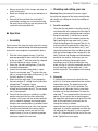
1
Chop and
mitre saw
Chop and mitre saw
PKGS 1450 LASER
Operating and safety instructions
Kompernaß GmbH
Burgstraße 21
D-44867 Bochum (Germany)
Last information update: 07 / 2007 · Ident.-No.: PKGS1450 Laser - 072007-1 / UK / IE
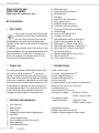
Before you begin reading this information, please unfold the page with the illustrations
and familiarize yourself with all functions of the tool.
GB / IE
Operating and safety instructions
Page
5
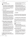
t y u
Q
W
E
r
R
T
Y
e
w
q
U
{
I}
O
Y
U
P
}
A
o
B
C
D
H
p
i
A
[
S
G
F
]
D
E
F
a
b
Y
c
d
e
f
Content
Before reading, unfold the page containing the illustrations
and familiarise yourself with all functions of the device.
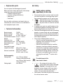
The following icons / symbols are used in this instruction manual:
V~
Read instruction manual!
W
Watt (performance)
Observe caution and safety notes!
n0
Rated idle running speed
Caution – electric shock!
Dangerous electric current – danger
to life!
wear ear protectors, a breathing /
dust mask and safety glasses.
Caution, laser!
Do not expose yourself to
laser radiation.
Protection category II
Voltage
To work safely
Introduction
Your safety......................................................................................................
Proper use......................................................................................................
Features and equipment..................................................................................
Included items.................................................................................................
Replaceable parts...........................................................................................
Technical information......................................................................................
Page Page Page Page Page Page 6
6
6
6
7
7
Safety advice relating specifically to this saw................................................. Page 7
Safety
Operation
Assembly........................................................................................................
Checking and setting your saw.......................................................................
Operation........................................................................................................
Connecting a dust extraction device................................................................
Unlocking and switching the machine on and off............................................
Switching the laser on and off and adjusting it................................................
Setting the speed............................................................................................
Transporting the machine................................................................................
Attaching the laminate cutting attachment and cutting laminate.....................
Mitre cuts – turning the saw table...................................................................
Inclined cuts – inclining the saw motor unit.....................................................
Making a combination cut...............................................................................
Changing a saw blade.....................................................................................
Tips and tricks................................................................................................
Page Page Page Page Page Page Page Page Page Page Page Page Page Page 9
9
10
10
11
11
11
11
11
11
12
12
12
12
Maintenance and cleaning ............................................................................. Page 13
Disposal........................................................................................................... Page 13
Cleaning
Information
Service............................................................................................................ Page Manufacturers’ declaration of conformity........................................................ Page 13
13
GB/IE
5
Introduction
Chop and mitre saw
PKGS 1450 LASER
Please make sure you familiarise yourself
fully with the way the device works before
you use it for the first time and that you
understand how to handle electrical power tools
correctly. Further details can be found in the operating
instructions.
In addition, you must also observe the general safety
advice contained in the accompanying booklet. Keep
these instructions in a safe place. If you pass the
device on to anyone else, please ensure that you
also pass on all the documentation.
P
{
}
q
w
e
r
t
y
u
i
o
p
[
]
A
S
D
F
G
H
Mitre angle scale
Laminate cutting attachment
Mounting holes
Stop plate
Saw motor unit setting knob
Rear support stirrup
Sawdust removal connector
Laser beam emission opening
Screw (for attaching the saw blade)
Outside flange
Laser On / Off switch (Fig. C)
Transport lock (Fig. A)
Saw blade depth setting screw (Fig. A)
Scale on the saw motor unit (Fig. A)
Mitre angle / 0° setting screw (Fig. A)
Saw motor unit mounting screws (Fig. A)
Mitre angle / 45° setting screw (Fig. B)
On / Off switch (Fig. C)
Rotation speed selector wheel (Fig. C)
Table insert (Fig. B)
Laser setting screw (Fig. B)
L
L
Included items
Chop, mitre and combination cuts
L Introduction
L
Your safety
Proper use
For sawing solid wood, chipboard and plastic. With
the laminate cutting attachment { in place the
machine is suitable for laminate and material up to
20 cm wide. Please note that the blade pre-installed
in the saw as supplied is intended for use with wood
only. Any other use or modification to the device shall
be considered as improper use and could give rise
to considerable dangers. The manufacturer will not
accept liability for loss or damage arising from
improper use. Not suitable for commercial use.
L
Features and equipment
Q
W
E
R
T
Y
U
I
O
Saw motor unit
Switch handle
Safety lever
Sliding roller (with automatic blade guard)
Saw table
Lateral support stirrup
Lateral support stirrup clamp screws
Mitre angle stop
Saw table setting knob
6
GB/IE
1 Chop and mitre saw
1 Laminate cutting attachment {
2 Lateral support stirrups Y
1 Sawdust collection bag (a)
2 Screw clamps (b)
2 Carbon brushes (c) (see section on maintenance)
2 Allen keys (d), sizes 5 mm and 6 mm
1 Locking spanner (e)
1 Socket spanner (13 mm) (f)
1 Universal saw blade: 250 x 30 x 2.35 mm,
80 HM - teeth (3.2 mm)
1 Saw blade for wood
(supplied installed):250 x 30 x 1.8 mm,
36 HM - teeth (3.0 mm)
1 Operating instructions
1 Booklet “Guarantee and service”
1 Booklet “Containing general safety advice”
Introduction / Safety
L
Replaceable parts
You can replace the following parts yourself.
When you do this always observe the relevant operating instructions and safety advice.
- Sawdust collection bag (a)
- Laminate cutting attachment {
- Stop plate q
- Saw blade
Have any other maintenance and repair tasks carried out by our service centre or an accredited electrical equipment repair centre.
L
Technical information
Nominal output:
1450 W
Nominal voltage:
230 V ~ 50 Hz
Nominal speed:
n0 1800 - 4500 min-1
Circumferential speed: 24 m / s – 55 m / s
Weight:
14.5 kg
Protection class:
II / &
Sound pressure level: Lp = 95.5 dB (A)
Sound power level:
Lw = 108.5 dB (A)
Vibration:
2.5 m / s2
Saw blade for wood
(supplied installed):250 x 30 x 1.8 mm,
36 HM - teeth (3.0 mm)
Universal saw blade:250 x 30 x 2.35 mm,
80 HM - teeth (3.2 mm)
Cutting capacity:
Cutting width:max. 140 mm (without
laminate cutting attachment)
max. 200 mm (with laminate
cutting attachment)
Cutting depth:
max. 65 mm
L Safety
Safety advice relating
specifically to this saw
J Ensure that the device is always used in accordance with the advice in these operating instructions and only by persons over 18 years of age.
J
Keep children away from the device.
Store the device indoors in an enclosed,
dry place where it cannot be reached
by children.
JIn addition, you must also read the advice in the
accompanying booklet containing safety advice
before using the device for the first time.
JCheck that all moving parts on the tool are working
properly, can move freely and are not damaged.
All parts must be correctly attached and fulfil all
the requirements necessary to allow the electrical
tool to operate properly.
JCarry out the following before each use:
-check the saw for damaged parts or safety
equipment and if necessary have them
replaced by an electrician.
- check the saw blade for quality / condition,
sharpness, cleanliness and free movement.
- check that the saw blade is properly attached
and does not wobble. Attach the saw blade
by placing the locking spanner (e) on the outer flange u and tightening the screw (for
attaching the saw blade) y counter-clockwise.
avoid danger to life
To
from electric shock:
J
Do not operate the device if the
mains lead or mains plug is damaged.
Caution! A damaged mains lead
presents a serious danger to life from electric
shock. The service centre for your country is
shown in the guarantee documentation.
JHave repairs carried out only by an electrician or
the relevant service centre.
GB/IE
7
Safety
J
Do not operate the device if it is
damp and do not use it in a damp
environment.
Protecting yourself from laser radiation:
Note: This product is a Class 1 Laser / Protection
Class III device. The radiation output under circumstances of proper use does not present any danger.
JThe chop and mitre saw is fitted with a laser.
Do not replace this laser with one of another
type. Repairs must be carried out only by one
of our authorised service partners.
JDo not look directly into the laser beam or into
the opening from which it is emitted.
JNever direct the laser beam on to reflective surfaces or at people or animals. Even a brief look
into a laser beam can damage your eyes.
J Never open the laser unit housing.
To avoid the danger of injury,
burning and dangers to your health:
JAlways check the device first under no-load
conditions. If you notice any strange noises or
vibrations from the device, switch it off immediately and pull the plug out of the mains socket.
Never use the device if it shows any of these
types of problems. Take it to be checked and if
necessarily repaired by an electrician.
JUse the machine only on the materials given in
the section on proper use.
JCheck that the saw motor unit Q is securely
attached.
JUse the machine only if the safety equipment is
properly positioned in its place as intended, the
machine is in good condition and has been
properly maintained.
JAlways keep the mains lead away from the
working area of the machine and lead away the
mains lead from the rear.
J
Look after your health – wear
ear protectors, safety glasses
and a breathing / dust mask.
JNever hold the saw at the rear. Remove sawing
8
GB/IE
waste, parts of workpieces or clamped objects
only when the machine’s mains plug is removed
from the mains socket and the saw has come to
a standstill.
JDo not cut workpieces too small. Your hand must
always be at least 10 cm away from the saw blade.
JDo not attempt to saw extremely small workpieces.
JEnsure that your work area is well lit
(250 - 300 Lux). Do not use the device in places
where there is a danger of fire or explosion, for
example near inflammable liquids or gases.
J If the table insert G is damaged have it replaced
immediately.
Danger! If the table insert is damaged it could
lead to the danger of small objects blocking the
saw blade by becoming trapped between the
table insert G and the saw blade. If the table
insert is damaged have it replaced immediately
by our customer service department.
To work safely:
JUse the machine only for the purposes indicated
and within the stipulated performance limits.
Do not overload the machine.
JKeep the handle clean, dry and free of oil and
grease.
JEnsure that the automatic blade guard R is
functioning properly and can move freely. Never
clamp the automatic blade guard so that it remains open.
JAlways select a saw blade that is suitable for
the material you intend to cut.
JSupport longer workpieces in such a way that
they are at the same level as the surface of the
saw table T.
JSecure the machine after use with the transport
lock o.
JUse the screw clamps (b) or other clamping
devices so that an awkwardly shaped workpiece
cannot rotate or move whilst you are sawing it. The
workpiece must be firmly clamped against the
base of the table and the stop plate so that there
are no gaps between the turntable and workpiece
or between the stop plate and the workpiece.
Safety / Operation
JAlways ensure that all the clamps and stops are
firmly held in place.
JNever saw through more than one workpiece at
a time.
JEnsure that the saw blade has reached full
speed before starting your cut and avoid using
too much force. In that way you will prevent the
saw blade from being blocked.
L Operation
L
Assembly
Do not connect the chop and mitre saw to the mains
before you have worked through the following assembly
instructions and completely assembled the device.
1.Slide the lateral support stirrups Y into the
openings provided for them on the left and right
of the saw table T until they meet the stop and
then fully tighten the clamp screws U.
2.Screw the saw table setting knob O into the
threaded hole provided.
3.Loosen the saw table setting knob O again.
Press the mitre angle stop I and turn the saw
table T using the saw table setting knob O into
the basic position (0° setting).
4.When the mitre angle stop I has engaged in
the basic position (0° setting), turn the saw table
setting knob O to tighten it again.
5.Lightly press the switch handle W downwards
and pull out the transport lock o. The saw motor
unit Q tips upwards.
6.Ensure that the machine is standing in a stable
position and check that the floor around the
machine is flat, clean and free of loose particles
such as sawdust chippings and sawing waste.
Using the four mounting holes } provided, fasten
the chop and mitre saw on to a firm, level surface.
7.If you have not fastened the machine tightly
down to a working surface, pull out the rear
support stirrup e as far as possible to provide
maximum support to the machine.
L
Checking and setting your saw
Warning! Always disconnect the mains supply
(by pulling the plug out of the mains socket) before
you change any settings or check the condition of
the machine.
1. Parallel saw blade
jCheck that the saw blade is correctly installed; it
must be parallel to the sawing slot in the table. To
make any necessary settings proceed as follows;
jBring the saw table T into the basic position
(0° setting). Release the transport restraint by
lightly pressing the saw motor unit Q downwards and pulling out the transport lock o. Unlock the machine by pushing the safety lever E
to the right. Lower the saw motor unit Q and
check that the side face of the saw blade is parallel
with the left hand edge of the sawing slot in the
table. The blade and the edge must be absolutely
parallel to one another. If necessary you can
change the setting by loosening the three
mounting screws A directly behind the saw
blade (see Fig. A) using the supplied 6 mm Allen
key (d) and bring the saw motor unit Q into
parallel alignment. Then retighten the mounting
screws.
2. Stop plate
jIt is particularly necessary to check the stop
plate q if it has been removed from the machine
and put back again. The stop plate must be
perpendicular (at 90°) to the saw blade. This
setting can only be made after the saw blade
has been set as described above. To check the
stop plate q, we recommend that you use a set
square. Set one end of the set square against
the stop plate and the other end against the side
face of the saw blade. If necessary you can
change the setting as follows:
jLoosen the two screws on the rear face of the
stop plate q using the supplied 6 mm Allen key
(d) and bring the stop plate q into a perpendicular (90°) alignment to the side face of the saw
blade. Tighten the screws again.
GB/IE
9
Operation
3. Saw blade depth
Wear protective gloves!
jCheck the depth of the saw blade by first lowering
the saw motor unit Q as far down as possible.
Then try turning the saw blade manually. It must
be able to turn freely. If the saw blade does not
turn freely, carry out the necessary adjustment
by turning the setting screw p.
4a. Mitre setting 0°
jIf necessary you can adjust the 0° mitre stop. Bring
the saw table T into the basic position (0°setting).
With the saw motor unit Q lowered, compare
the alignment of the side face of the saw blade
with the workpiece support surface of the table
using a set square.
To make the adjustment, first loosen the lock
nut on the setting screw ] (see Fig. A) and then
turn the screw with the supplied 5 mm Allen key
(d). Take off the Allen key – readjust until the
saw blade is at 90° to the saw table. Tighten the
locknut on the setting screw ] . The saw blade
must be at right angles to the saw table and the
scale on the saw motor unit Q must read 0°.
4b.Mitre setting 45° (inclined cut setting)
jSet the saw table T into the basic position
(0° setting). Loosen the setting knob w and
incline the saw motor unit Q until the 45°
setting on the scale [ on the saw motor unit
is reached. Retighten the setting knob q and
lower the saw motor unit Q.
jUse a combination set square to check the angle
of the side face of the saw blade with respect to
the workpiece support area of the saw table. To
make the adjustment first loosen the lock nut on
the setting screw S (see Fig. B) and then turn
the screw with the supplied 5 mm Allen key (d).
Take off the Allen key – readjust until the saw
blade is at 45° to the saw table. Tighten the
locknut on the setting screw S.
5. Adjusting the pointer on the scale [
If the pointer when it is in the basic setting is not in
line with the 0° marking on the scale then adjust the
pointer as follows:
10
GB/IE
jFirst make sure that the basic settings 0° and
45° have been carried out correctly as described in sections 4a and 4b.
jLoosen the setting knob w and incline the saw
motor unit Q into the 45° setting.
jLoosen the pointer screw with a cross-head
screwdriver and adjust the pointer until it is in
line with the 45° marking and tighten the screw
again. After you have returned the saw motor
unit Q into the 0° position, the pointer should
again be exactly in line with the 0° marking on
the scale. If necessary repeat the adjustment
process until the pointer is correctly set.
L
Operation
Take note of the mains voltage! The voltage must agree
with that shown on the machine rating plate (equipment shown as 230 V can also be connected to 220 V).
L
Connecting a dust extraction device
The dust created when sawing can be inflammable,
explosive and hazardous to health. Some dusts are
carcinogenic. Use a suitable dust extraction device
designed for the purpose and wear a dust protection
mask.
Wear a dust mask!
External vacuum extraction:
jConnect a vacuum extraction device of a type
specifically suitable for dust extraction to the
sawdust removal connector r. Ensure that you
connect and use it properly.
Sawdust collection bag (a):
jAttach the sawdust collection bag (a) to the sawdust removal connector r by pressing the
lugs of the wire ring together. Engage the wire
ring in the groove provided in the sawdust removal connector.
jTo remove the sawdust collection bag (a) from
the sawdust removal connector r you also
press the lugs of the wire ring together.
Operation
Empty the sawdust collection bag regularly.
Open the zip fastener to empty the bag.
L U
nlocking and switching
the machine on and off
jUnlock the machine by pushing the safety lever E
to the right.
Switching on:
jPress the On / Off switch D and keep it pressed.
Note: There is a delay in the machine starting up
.
Switching off:
j Release the On / Off switch D.
jSecure the machine again by moving the saw
motor unit Q downwards and pressing the
transport lock o to the left.
LSwitching the laser on and off
and adjusting it
Avoiding harm from the laser beam!
The laser beam indicates the cutting line of the saw
blade. Align the marks on your workpiece with the
track of the laser beam.
Switching on:
j Press the laser On / Off switch i into position I.
Switching off:
j Press the laser On / Off switch i into position 0.
Adjusting the laser beam:
jTurn the laser setting screw H to adjust the
laser beam.
L
Setting the speed
You can pre-select the speed you require using
the rotation speed selector wheel F.
Increasing speed:
jTurn the rotation speed selector wheel F
towards marking 6 or in the + direction
(6= highest speed).
Reducing speed:
jTurn the rotation speed selector wheel F
towards marking 1 or in the – direction
(1= lowest speed).
L
Transporting the machine
jBefore you transport the machine always lock
the transport restraint by engaging the transport
lock o with the saw motor unit Q lowered.
When you carry the machine always hold it by
the base.
LAttaching the laminate cutting
attachment and cutting laminate
The patented laminate cutting attachment { allows
you to cut laminate to your required lengths quickly
and cleanly. Note that the laminate cutting attachment { is designed exclusively for laminate and
a material width of up to 20 cm. It is suitable for
almost all types of commercially available laminate
floor coverings.
jLoosen the two stop plate q setting screws
using the supplied 6 mm Allen key (d) and remove the stop plate.
jInsert in its place the laminate cutting attachment { and screw it to the saw table T.
jPlace the laminate flush against the edge of
the stop of the laminate cutting attachment { .
L
Mitre cuts – turning the saw table
jLoosen the setting knob for saw table O. Press
the mitre angle stop I and turn the saw table T
using the saw table setting knob O to the left or
right into the desired position. Release the mitre
angle stop I again and tighten the saw table
setting knob O.
GB/IE
11
Operation
For use with standard cuts, the mitre angle scale P
has easily engaged fixed stop points for the most
common positions, 0°, 15°, 22.5°, 30° and 45°.
LInclined cuts – inclining the saw
motor unit
With the PKGS 1450 LASER you can make inclined
cuts between 90° and 45°.
jLoosen the setting knob w and using the scale
on the saw motor unit [ set the angle for your
inclined cut. After you have set the angle and
before you make your cut make sure that you
tighten the setting knob w again.
L
Making a combination cut
To make a combination cut you have to incline the
saw motor unit Q and turn the saw table (see the
sections “Mitre cuts” and “Inclined cuts”).
L
Changing a saw blade
Warning! Always make sure that the mains plug
is out of the socket before doing any work on the
device. With the saw motor unit lowered, first lock
the machine by engaging the transport lock o.
jAlways ensure that the saw blades you use are
as described in the section “Included items”,
comply with EN 847-1 and are properly sharpened. Always use saw blades that have a diameter of 250 mm and blade flanges specified for
this saw. Saw blades with hardened metal teeth
must have a positive cutting angle.
jDo not use saw blades that have deep hook teeth.
jDo not use saw blades that are recommended
for use at less than 4500 revolutions per minute.
jDo not use saw blades that are made from HSS
(high-speed steel). Do not use saw blades that
are damaged or deformed.
jDo not use spacer pieces or spindle rings in order
to allow other sizes of saw blade to be fitted.
12
GB/IE
Saw blades must be protected during transport
to prevent injury.
Wear protective gloves!
jInsert the locking spanner (e) into the outer
flange u and hold it in place.
jPlace the wrench / socket spanner (f) into the
screw head and release the screw by turning it
clockwise. Remove the screw y and the outer
flange u.
jUnlock the device by pulling out the transport
lock o and carefully tilting the saw motor unit Q
upwards. Caution - danger of injury!
The saw blade may have become loose.
jUnlock the automatic blade guard R by pushing
the safety lever E to the right. Push the automatic blade guard R upwards.
jNow you can remove the blade by moving it
downwards.
The process for installing a saw blade is the reverse
(put on the flange, tighten the screw in the counterclockwise direction). Always check that you have
inserted the saw blade so that it rotates in the correct
direction. You will find the direction of rotation marked
on the saw blade and the saw motor unit Q.
Saw blade parameters:
Diameter x bore:
Blade width:
Tooth width:
L
250 x 30 mm
1.8 - 2.35 mm
max. 3.0 - 3.2 mm
Tips and tricks
jNever position a curved workpiece in such a
way that it curves away from the stop plate q.
Any gap between the stop plate and the workpiece would cause the saw blade to be blocked
during the cutting process.
You can find further practical tips on electrical tools
in the accompanying booklet containing safety advice.
Cleaning / Disposal / Information
L Cleaning
LManufacturers’ declaration of
L
We, Kompernaß GmbH, Burgstr. 21, D-44867 Bochum,
Germany, declare that this product complies with the
following EU directives:
Maintenance and cleaning
Warning! Always make sure that the mains plug is
out of the socket before doing any work on the device.
jWhen replacement becomes necessary the supplied spare carbon brushes (c) must be installed
only by an authorised electrician.
jClean the sliding roller and the automatic blade
guard R so that they move freely.
jDo not allow any liquids to enter the machine.
Use a cloth or a thin brush to clean the housing.
Remove dust / splinters by blowing with compressed air.
L Disposal
The packaging is made from environmentallyfriendly material and can be disposed off at
your local recycling plant.
Do not dispose of electrical tools with
the household rubbish!
In accordance with European Directive 2002 / 96 / EC
about waste electrical and electronic equipment and
its transposition into national legislation, worn out
electrical tools must be collected separately and
taken for environmentally compatible recycling.
Please contact your local council office to find out about
disposal facilities for your worn-out electrical tools.
conformity
Machinery Directive: (98 / 37 / EC)
EC Low Voltage Directive (2006 / 95 / EEG)
Electromagnetic compatibility: (89 / 336 / EEC)
Applicable harmonised standards:
EN55014-1
EN55014-2
EN61000-3-2
EN61000-3-3
EN61000-6-1
EN61000-6-3
EN61029-1
EN61029-2-9
EN60825-1
Description of the product:
Chop and mitre saw PKGS 1450 LASER
Bochum, 31.07.2007
Hans Kompernaß
- Managing Director -
L Information
L
Service
The service centre for your country is shown in the
guarantee documentation.
We reserve the right to make technical modifications in the course
of further development.
GB/IE
13
14
15
16