1
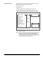
Document Scanner
5500 and 7500
Installation Questionnaire
Instructions
A-61074
Part Number 6C3944
Mode Setup Software
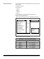
Table of contents
A-61074 April 1997
1 Introduction . . . . . . . . . . . . . . . . . . . . . . . . . . . . . . . . . . . . .
Installation requirements . . . . . . . . . . . . . . . . . . . . . . . . . . . .
Installation procedure . . . . . . . . . . . . . . . . . . . . . . . . . . . . . .
Logon procedure . . . . . . . . . . . . . . . . . . . . . . . . . . . . . . . . . .
Using the Mode Setup Software . . . . . . . . . . . . . . . . . . . . . .
Using the Mode Setup Software Questionnaire and
Instructions . . . . . . . . . . . . . . . . . . . . . . . . . . . . . . . . . . . . . .
Logout procedure . . . . . . . . . . . . . . . . . . . . . . . . . . . . . . . . .
1-1
1-1
1-1
1-2
1-3
2 Scanner configuration items . . . . . . . . . . . . . . . . . . . . . . .
Accessing the Configuration Items Menu . . . . . . . . . . . . . . .
Display language . . . . . . . . . . . . . . . . . . . . . . . . . . . . . . . .
Measurement system . . . . . . . . . . . . . . . . . . . . . . . . . . . .
Date format . . . . . . . . . . . . . . . . . . . . . . . . . . . . . . . . . . . .
Description 1: Date Format Samples . . . . . . . . . . . . . .
Time format . . . . . . . . . . . . . . . . . . . . . . . . . . . . . . . . . . . .
Description 2: Time Format Samples . . . . . . . . . . . . . .
Set time and date . . . . . . . . . . . . . . . . . . . . . . . . . . . . . . .
Confirmation tone volume . . . . . . . . . . . . . . . . . . . . . . . . .
Confirmation tones . . . . . . . . . . . . . . . . . . . . . . . . . . . . . .
Fixed field delimiter . . . . . . . . . . . . . . . . . . . . . . . . . . . . . .
Description 3: Fixed Field Delimiter Samples . . . . . . . .
Printer messages . . . . . . . . . . . . . . . . . . . . . . . . . . . . . . .
Version numbers . . . . . . . . . . . . . . . . . . . . . . . . . . . . . . . .
Load scanner from laptop . . . . . . . . . . . . . . . . . . . . . . . . .
Load laptop from scanner . . . . . . . . . . . . . . . . . . . . . . . . .
2-1
2-1
2-2
2-3
2-4
2-4
2-5
2-5
2-6
2-8
2-9
2-10
2-10
2-11
2-12
2-13
2-14
3 Mode configuration . . . . . . . . . . . . . . . . . . . . . . . . . . . . . . .
Accessing the Mode Configuration Menu . . . . . . . . . . . . . . .
Mode-to-mode copying . . . . . . . . . . . . . . . . . . . . . . . . . . . . .
Selecting a mode for configuration . . . . . . . . . . . . . . . . . . . .
Mode Configuration Items descriptions . . . . . . . . . . . . . . . . .
Index format . . . . . . . . . . . . . . . . . . . . . . . . . . . . . . . . . . .
Description 1: Index Formats . . . . . . . . . . . . . . . . . . . .
IA Field width . . . . . . . . . . . . . . . . . . . . . . . . . . . . . . . . . . .
Field A (Level 1) . . . . . . . . . . . . . . . . . . . . . . . . . . . . . .
Field B (Level 2) . . . . . . . . . . . . . . . . . . . . . . . . . . . . . .
Field C (Level 3) . . . . . . . . . . . . . . . . . . . . . . . . . . . . . .
Fixed field . . . . . . . . . . . . . . . . . . . . . . . . . . . . . . . . . . .
Description 2: Image Address Fields . . . . . . . . . . . .
Description 3: Image Address Field Width Defaults .
Level rules . . . . . . . . . . . . . . . . . . . . . . . . . . . . . . . . . . . . .
Level to follow level 0 . . . . . . . . . . . . . . . . . . . . . . . . . . .
Level to follow level 1 . . . . . . . . . . . . . . . . . . . . . . . . . . .
Level to follow level 2 . . . . . . . . . . . . . . . . . . . . . . . . . . .
Level to follow level 3 . . . . . . . . . . . . . . . . . . . . . . . . . . .
Description 4: Level Rule Options and Defaults . . . .
3-1
3-1
3-2
3-4
3-4
3-5
3-6
3-8
3-9
3-10
3-11
3-12
3-13
3-14
3-15
3-16
3-17
3-18
3-19
3-20
1-4
1-4
i
IA Display format . . . . . . . . . . . . . . . . . . . . . . . . . . . . . . . .
Adjoining IA . . . . . . . . . . . . . . . . . . . . . . . . . . . . . . . . . . . .
Batching . . . . . . . . . . . . . . . . . . . . . . . . . . . . . . . . . . . . . .
Length monitor . . . . . . . . . . . . . . . . . . . . . . . . . . . . . . . . .
On/off . . . . . . . . . . . . . . . . . . . . . . . . . . . . . . . . . . . . . . .
Minimum length . . . . . . . . . . . . . . . . . . . . . . . . . . . . . . .
Maximum length . . . . . . . . . . . . . . . . . . . . . . . . . . . . . .
Error response . . . . . . . . . . . . . . . . . . . . . . . . . . . . . . . .
Skew monitor . . . . . . . . . . . . . . . . . . . . . . . . . . . . . . . . . . .
On/off . . . . . . . . . . . . . . . . . . . . . . . . . . . . . . . . . . . . . . .
Detection range . . . . . . . . . . . . . . . . . . . . . . . . . . . . . . .
Error response . . . . . . . . . . . . . . . . . . . . . . . . . . . . . . . .
Footswitch . . . . . . . . . . . . . . . . . . . . . . . . . . . . . . . . . . . . .
Press definition . . . . . . . . . . . . . . . . . . . . . . . . . . . . . . .
Confirmation tone . . . . . . . . . . . . . . . . . . . . . . . . . . . . .
Release definition . . . . . . . . . . . . . . . . . . . . . . . . . . . . .
Patch reader . . . . . . . . . . . . . . . . . . . . . . . . . . . . . . . . . . .
On/off . . . . . . . . . . . . . . . . . . . . . . . . . . . . . . . . . . . . . . .
Transfer patch definition . . . . . . . . . . . . . . . . . . . . . . . .
Confirmation tone . . . . . . . . . . . . . . . . . . . . . . . . . . . . .
Level transfer on T-Patch . . . . . . . . . . . . . . . . . . . . . . . .
OCR . . . . . . . . . . . . . . . . . . . . . . . . . . . . . . . . . . . . . . . . .
COIN2 Port Select . . . . . . . . . . . . . . . . . . . . . . . . . . . . . . .
Bar code reader . . . . . . . . . . . . . . . . . . . . . . . . . . . . . . . . .
On/off . . . . . . . . . . . . . . . . . . . . . . . . . . . . . . . . . . . . . . .
Bar code type . . . . . . . . . . . . . . . . . . . . . . . . . . . . . . . .
Codes per document . . . . . . . . . . . . . . . . . . . . . . . . . . .
Minimum code length . . . . . . . . . . . . . . . . . . . . . . . . . .
Maximum code height . . . . . . . . . . . . . . . . . . . . . . . . . .
Scan direction . . . . . . . . . . . . . . . . . . . . . . . . . . . . . . . .
Code quality . . . . . . . . . . . . . . . . . . . . . . . . . . . . . . . . .
Confirmation tone . . . . . . . . . . . . . . . . . . . . . . . . . . . . .
Bar code location . . . . . . . . . . . . . . . . . . . . . . . . . . . . . .
Printer controller . . . . . . . . . . . . . . . . . . . . . . . . . . . . . . . .
IA Print format . . . . . . . . . . . . . . . . . . . . . . . . . . . . . . . .
Font size . . . . . . . . . . . . . . . . . . . . . . . . . . . . . . . . . . . .
Character orientation . . . . . . . . . . . . . . . . . . . . . . . . . . .
Front printer . . . . . . . . . . . . . . . . . . . . . . . . . . . . . . . . . . . .
On/off . . . . . . . . . . . . . . . . . . . . . . . . . . . . . . . . . . . . . . .
Print definition . . . . . . . . . . . . . . . . . . . . . . . . . . . . . . . .
Vertical start print position . . . . . . . . . . . . . . . . . . . . . . .
Rear printer . . . . . . . . . . . . . . . . . . . . . . . . . . . . . . . . . . . .
On/off . . . . . . . . . . . . . . . . . . . . . . . . . . . . . . . . . . . . . . .
Print definition . . . . . . . . . . . . . . . . . . . . . . . . . . . . . . . .
Vertical start print position . . . . . . . . . . . . . . . . . . . . . . .
Mode name . . . . . . . . . . . . . . . . . . . . . . . . . . . . . . . . . . . .
Overrides . . . . . . . . . . . . . . . . . . . . . . . . . . . . . . . . . . . . . .
Exiting the mode configuration menu . . . . . . . . . . . . . . . .
3-22
3-23
3-24
3-24
3-25
3-26
3-27
3-28
3-29
3-30
3-31
3-32
3-33
3-34
3-35
3-36
3-37
3-38
3-39
3-40
3-41
3-42
3-42
3-43
3-44
3-45
3-46
3-47
3-48
3-49
3-50
3-51
3-52
3-53
3-54
3-55
3-56
3-57
3-58
3-59
3-61
3-62
3-63
3-64
3-66
3-67
3-68
3-69
Appendix A Default summaries . . . . . . . . . . . . . . . . . . . . . . . A-1
Appendix B Language support . . . . . . . . . . . . . . . . . . . . . . . . B-1
ii
A-61074 April 1997
1
Introduction
The Kodak Digital Science™ Mode Setup Software 5000/7000 has
been developed to enable you to customize applications using the
Kodak Digital Science Document Scanner 5500 and 7500.
The Mode Setup Software offers a user-friendly interface which
allows you to perform an initial installation or modification of an
existing setup.
The following sections describe the installation requirements,
installation procedure, logon procedure, general information
regarding use of the Mode Setup Software, the Installation
Instructions and the Installation Questionnaire, and the logout
procedure.
Installation
requirements
The following system and cabling requirements should be verified
prior to attempting to use the Mode Setup Software.
Minimum system requirements
• IBM or IBM-compatible personal computer with access to the
DOS command prompt.
• 640K RAM.
• 1.2 MB hard disk space.
• a 720K 3 1/2" disk drive.
• monochrome or color display.
Installation procedure
The installation procedure is as follows:
1. Insert the Mode Setup Software diskette into the disk drive of
the PC.
2. Change to the directory (i.e., “mkdir setup” or “cd setup”) where
the software will be installed.
3. Copy the software from the diskette to the desired directory by
typing:
Copy A:*.*
If the disk drive on your PC is not deisgnated as the A drive,
substitute the correct drive in the above command string.
A-61074 April 1997
1-1
Logon procedure
After the installation procedure is completed, perform the following
steps to logon to the Mode Setup Software:
1. Access DOS.
2. Change the directory to correspond to the directory designated
during the installation procedure.
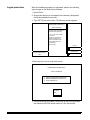
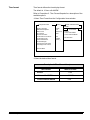
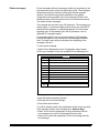
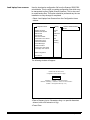
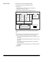
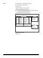
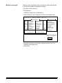
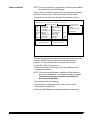
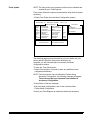
3. Type SETUP and press Enter. The following screen appears:
KODAK DIGITAL SCIENCE (tm)
Scanner 5000/7000
This software is the property of
Eastman Kodak Company.
It is not to be sold or leased
in any form.
Use by any unauthorized
persons is illegal and is
subject to penalties under
the copyright laws of the
United States.
Strike any key.
Version
3.20e
Release Date
Copyright
Eastman Kodak Company
1993
Jan 10, 1997
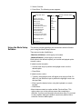
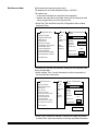
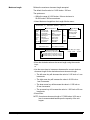
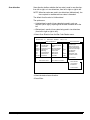
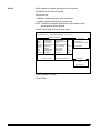
• Press any key to move to the next screen.
KODAK DIGITAL SCIENCE (tm)
Scanner 5000/7000
1) Attach RS-232 Cable to COIN1/3 Port
2) DIGITAL SCIENCE Power Switch On
3) Press <ENTER> key
Continue
Exit
4. Verify that the RS-232 cable is connected to the COIN3 port and
the Scanner 5500/7500 power switch is in the ON position.
1-2
A-61074 April 1997
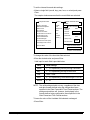
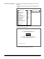
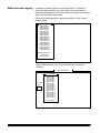
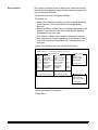
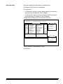
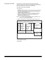
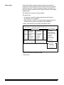
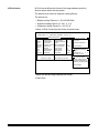
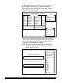
5. Select Continue.
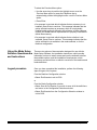
6. Press Enter. The following screen appears:
Configuration Items
Display Language
Measurement System
Date Format
Time Format
Set Time and Date
Confirmation Tone Volume
Confirmation Tones
Fixed Field Delimiter
Printer Messages
Version Numbers
Load scanner from laptop
Load laptop from scanner
Setting
DIGITAL SCIENCE Status
READY
English
Inch
1990/10/10
00:00
Soft
Enabled
Period (.)
Mode Configuration
End Session
Using the Mode Setup
Software
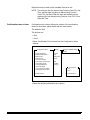
This section provides guidelines and conventions which will assist
you in using the Mode Setup Software.
There are two levels of definitions:
• Machine definitions—which apply to all modes.
• Mode definitions— which apply to one mode.
Each option to be defined requires you to select a displayed option
or enter a value.
If asked to select an option:
— Use the arrow keys to position the highlight cursor over the
desired option.
— Press Enter.
If asked to enter a value:
— Typically, the highlight cursor will appear over the input field; if it
does not, use the arrow keys to position the highlight cursor over
the input field.
— Enter (type) the desired value, using the keyboard or numeric
keypad.
— Press Enter.
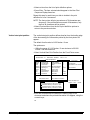
• Most windows contain an option entitled Previous Menu. This
option returns you to the previous menu after completing a
definition. If you are not returned to the previous menu, or you want
to return without altering the default or previously defined value,
select the Previous Menu option.
A-61074 April 1997
1-3
To select the Previous Menu option:
— Use the arrow keys to position the highlight cursor over the
Previous Menu option or press the Pagedown key to
automatically position the highlight cursor over the Previous Menu
option.
— Press Enter.
• If a message is received which indicates that an accessory is not
installed, press Enter to continue. This message indicates that the
option selected requires an accessory which is not physically
installed and/or properly defined to the software. In either instance,
contact your Kodak service representative to properly install and/or
define the accessory.
• If a message is received which indicates that a selection is not
available, press Enter to continue. This message indicates that the
option selected is not available in the mode selected, or for the
machine configuration.
Using the Mode Setup
Software Questionnaire
and Instructions
There are two pieces of documentation designed for use with the
Mode Setup Software: the Installation Instructions, which provide
information on how to install, access and use the software to define
the available options; and the Installation Questionnaire, which
provides a convenient form on which to record all of the machine and
mode definitions.
Logout procedure
Once you have completed the installation, perform the following
steps to logout of the system.
From the Machine Configuration window:
• Select End Session to exit to DOS.
or
From the Mode Configuration window:
• Select Save & End Session if you wish to save all of the definitions
and return to the Configuration Selection window.
• Select End Session from the Configuration Selection window to
exit to DOS.
1-4
A-61074 April 1997
2
Scanner configuration items
Accessing the
Configuration Items
Menu
Configuration Items
Display Language
Measurement System
Date Format
Time Format
Set Time and Date
Confirmation Tone Volume
Confirmation Tones
Fixed Field Delimiter
Printer Messages
Version Numbers
Load scanner from laptop
Load laptop from scanner
Setting
DIGITAL SCIENCE Status
READY
English
Inch
1990/10/10
00:00
Soft
Enabled
Period (.)
Mode Configuration
End Session
A-61074 April 1997
2-1
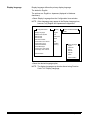
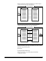
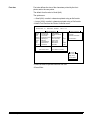
Display language
Display language defines the primary display language.
The default is English.
The options are: English or Japanese (displayed in Katakana
characters).
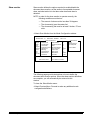
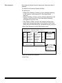
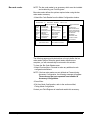
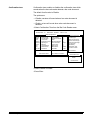
• Select Display Language from the Configuration Items window.
NOTE: Other languages may appear in the Display Language box;
however, only English and Japanese are supported.
Configuration Items
Setting
Display Language
Measurement System
Date Format
Time Format
Set Time and Date
Confirmation Tone Volume
Confirmation Tones
Fixed Field Delimiter
Printer Messages
Load scanner from laptop
Load laptop from scanner
English
Inch
1990/10/10
00:00
Soft
Enabled
Period (.)
Previous Menu
DIGITAL SCIENCE Status
READY
Display Language
English
Japanese
French
German
Spanish
Italian
Previous Menu
• Select the desired language option.
NOTE: The display language may also be altered using Function
Code F19—Display Language.
2-2
A-61074 April 1997
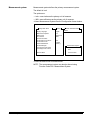
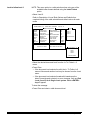
Measurement system
Measurement system defines the primary measurement system.
The default is Inch.
The options are:
— Inch—uses inches as the primary unit of measure.
— Milli—uses millimetres as the primary unit of measure.
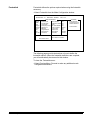
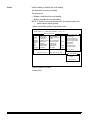
• Select Measurement System from the Configuration Items window.
Configuration Items
Display Language
Measurement System
Date Format
Time Format
Set Time and Date
Confirmation Tone Volume
Confirmation Tones
Fixed Field Delimiter
Printer Messages
Load scanner from laptop
Load laptop from scanner
Setting
DIGITAL SCIENCE Status
READY
English
Inch
1990/10/10
00:00
Soft
Enabled
Period (.)
Previous Menu
Measurement System
Inch
Milli
Previous Menu
• Select the desired unit of measurement.
NOTE: The measurement system may also be altered using
Function Code F20—Measurement System.
A-61074 April 1997
2-3
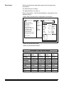
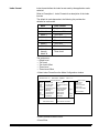
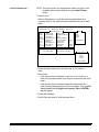
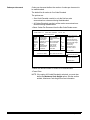
Date format
Date format defines the date display format; both the date format
and delimiter.
The default format is mmddyy.
The default delimiter is a slash (/ ).
Refer to Description 1: Date Format Samples for a description of the
available options.
• Select Date Format from the Configuration Items window.
Configuration Items
Display Language
Measurement System
Date Format
Time Format
Set Time and Date
Confirmation Tone Volume
Confirmation Tones
Fixed Field Delimiter
Printer Messages
Load scanner from laptop
Load laptop from scanner
Setting
English
Inch
1990/10/10
00:00
Soft
Enabled
Period (.)
DIGITAL SCIENCE Status
READY
yyyymmdd
mmddyy
mmdd
ddmmmyy
ddmmm
mmyy
yddd
yyddd
ddmmyy
Slash
Dash
Period
Space
Previous Menu
Date Format
mm = [01-12]
mmm = [JAN, FEB,
MAR . . .]
= [01-31]
dd
ddd = [001-366]
= [0-9]
y
= [00-99]
yy
yyyy = [19902089]
Date Delimiter
("/")
("-")
(".")
(" ")
Previous Menu
• Select the desired date format.
• Select the desired date delimiter.
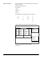
Description 1: Date Format Samples
2-4
Sample Date
March 1, 1994
Slash
Dash
Period
Space
mmddyy
03/01/94
03–01–94
03.01.94
03 01 94
mmdd
03/01
03–01
03.01
03 01
ddmmmyy
01/MAR/94
01–MAR–94 01.MAR.94
01 MAR 94
ddmmm
01/MAR
01–MAR
01.MAR
01 MAR
mmyy
03/94
03–94
03.94
03 94
yyddd
94/060
94–060
94.060
94 060
ddmmyy
01/03/94
01–03–94
01.03.94
01 03 94
yddd
4/060
4–060
4.060
4 060
yyyymmdd
1994/03/01
1994–03–01 1994.03.01
1994 03 01
A-61074 April 1997
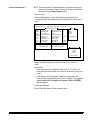
Time format
Time format defines the time display format.
The default is 12 hour with AM/PM.
Refer to Description 2: Time Format Samples for a description of the
available options.
• Select Time Format from the Configuration Items window.
Configuration Items
Setting
Display Language
Measurement System
Date Format
Time Format
Set Time and Date
Confirmation Tone Volume
Confirmation Tones
Fixed Field Delimiter
Printer Messages
Load scanner from laptop
Load laptop from scanner
English
Inch
1990/10/10
00:00
Soft
Enabled
Period (.)
DIGITAL SCIENCE Status
READY
Time Format
24 Hour
12 Hour with AM/PM
12 Hour without AM/PM
Previous Menu
Previous Menu
• Select the desired time format.
Description 2: Time Format Samples
Time Format
A-61074 April 1997
What Is Printed
24 hour
17:00
12 hour with AM/PM
5:00 PM
12 hour without AM/PM
5:00
2-5
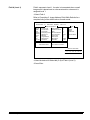
Set time and date
Set time and date sets the system clock.
The default time is 00:00; the default date is 10/10/90.
The options are:
— to set each individual time and date field separately.
— transfer the internal time and date settings of the computer used
during configuration to set the system clock.
• Select Set Time and Date from the Configuration Items window
and press Enter.
Configuration Items
Setting
Display Language
Measurement System
Date Format
Time Format
Set Time and Date
Confirmation Tone Volume
Confirmation Tones
Fixed Field Delimiter
Printer Messages
Load scanner from laptop
Load laptop from scanner
English
Inch
1990/10/10
00:00
Soft
Enabled
Period (.)
DIGITAL SCIENCE Status
READY
Set Time and Date
Date
Set Month
Set Day
10/10/1990
Set Year
Set Hour
Set Minute
Time
Laptop Time
00:04
Previous Menu
Previous Menu
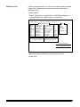
To transfer the internal time and date settings of the computer used
during configuration:
• Select Laptop Time. You will be asked to confirm the transfer of
the time and date information.
Configuration Items
Display Language
Measurement System
Date Format
Time Format
Set Time and Date
Confirmation Tone Volume
Confirmation Tones
Fixed Field Delimiter
Printer Messages
Load scanner from laptop
Load laptop from scanner
Setting
English
Inch
1990/10/10
00:00
Soft
Enabled
Period (.)
DIGITAL SCIENCE Status
READY
Set Time and Date
Date
Set Month
Set Day
10/15/1993
Set Year
Set Hour
Set Minute
Time
Laptop Time
12:42
Previous Menu
Previous Menu
Yes
No
• Select Yes to initiate the transfer of the time and date information;
or select No to cancel the transfer of the time and date information.
2-6
A-61074 April 1997
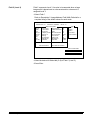
To set the internal time and date settings:
• Select a single field (month, day, year, hour, or minute) and press
Enter.
The sample window assumes that the month field was selected.
Configuration Items
Setting
Display Language
Measurement System
Date Format
Time Format
Set Time and Date
Confirmation Tone Volume
Confirmation Tones
Fixed Field Delimiter
Printer Messages
Load scanner from laptop
Load laptop from scanner
English
Inch
1990/10/10
00:00
Soft
Enabled
Period (.)
DIGITAL SCIENCE Status
READY
Set Time and Date
Date
Set Month
Set Day
10/10/1990
Set Year
Set Hour
Set Minute
Time
Laptop Time
00:04
Previous Menu
Previous Menu
Enter new month below
10
To Change: Enter Value
To Retain: Press ENTER
To change the value of the time/date field selected:
• Enter the desired value and press Enter.
Valid input for each field is provided below:
Field
Valid settings
Month
1 – 12, representing January through December
Day
1 – 31, representing the day of the month
Year
1990 – 2089
Hour
0 – 23, representing 12:00 AM through 11:00 PM
Minute
0 – 59
NOTE: The valid settings should not vary, regardless of the time
and date formats defined using the configuration items
specified in the Date Format and Time Format sections. The
settings entered here will, however, be displayed in the
formats defined using configuration items specified in the
Date Format and Time Format sections.
To leave the value of the time/date field selected unchanged:
• Press Enter.
A-61074 April 1997
2-7
Repeat this step for each of the time/date fields to be set.
NOTE: The time may also be altered using Function Code F21–Set
Time; and the date may also be altered using Function
Code F22—Set Date. Both the time and the date may be
displayed (but not altered) using Function Code F23—View
Date and Time.
Confirmation tone volume
Confirmation tone volume defines the volume of the confirmation
tones (for footswitch, patch reader and bar code reader).
The default is Soft.
The options are:
— Soft
— Loud
• Select Confirmation Tone Volume from the Configuration Items
window.
Configuration Items
Display Language
Measurement System
Date Format
Time Format
Set Time and Date
Confirmation Tone Volume
Confirmation Tones
Fixed Field Delimiter
Printer Messages
Load scanner from laptop
Load laptop from scanner
Setting
DIGITAL SCIENCE Status
READY
English
Inch
1990/10/10
00:00
Soft
Enabled
Period (.)
Previous Menu
Tone Volume
Soft
Loud
Previous Menu
• Select the desired confirmation tone volume.
2-8
A-61074 April 1997
Confirmation tones
Confirmation tones enables or disables all confirmation tones (for
footswitch, patch reader and bar code reader).
The default is Enable.
The options are:
—Enable—indicates that confirmation tones may be used.
—Disable—indicates that confirmation tones may not be used.
• Select Confirmation Tones from the Configuration Items window.
Configuration Items
Setting
Display Language
Measurement System
Date Format
Time Format
Set Time and Date
Confirmation Tone Volume
Confirmation Tones
Fixed Field Delimiter
Printer Messages
Load scanner from laptop
Load laptop from scanner
English
Inch
1990/10/10
00:00
Previous Menu
DIGITAL SCIENCE Status
READY
Soft
Enabled
Period (.)
Confirmation Tones
Disable
Enable
Previous Menu
• Select Disable or Enable.
NOTE: If you select Disable, all confirmation tones are permanently
disabled. If you select Enable, any confirmation tone
(footswitch, patch reader, or document scanning array/bar
code reader) must also be enabled at the mode level using
the appropriate Mode Configuration item.
A-61074 April 1997
2-9
Fixed field delimiter
Fixed field delimiter defines the fixed field delimiter used in the image
address display.
The default is Period (.).
The options are:
— Slash (/)
— Dash (–)
— Period (.)
— Space ( )
Refer to Description 3: Fixed Field Delimiter Samples for a
description of the available options.
• Select Fixed Field Delimeter from the Configuration Items window.
Configuration Items
Setting
Display Language
Measurement System
Date Format
Time Format
Set Time and Date
Confirmation Tone Volume
Confirmation Tones
Fixed Field Delimiter
Printer Messages
Load scanner from laptop
Load laptop from scanner
English
Inch
1990/10/10
00:00
DIGITAL SCIENCE Status
READY
Soft
Enabled
Period (.)
Fixed Field Delimeter
Slash ("/")
Dash ("-")
Period (".")
Space (" ")
Previous Menu
Previous Menu
• Select the desired Fixed Field delimiter.
Description 3: Fixed Field Delimiter Samples
2-10
Delimiter
What Is Displayed
Slash (/)
FFF/CC.BB.AAA
Dash (–)
FFF–CC.BB.AAA
Period (.)
FFF.CC.BB.AAA
Space ( )
FFF CC.BB.AAA
A-61074 April 1997
Printer messages
Printer messages define the messages which may be printed by the
front document printer and/or rear document printer. The messages
defined here may be printed by including the desired message
number in the document printer print definitions using Mode
Configuration items specified in the Front Document Printer Print
Definitions and/or Rear Document Printer Print Definitions sections.
The default is blank messages.
The message text may have up to 38 characters. The message may
contain upper- or lowercase alphanumerics and/or any other ASCII
character which appears on a standard keyboard. For information
regarding input of nonstandard (non-ASCII) characters, refer to
Appendix B, Language support.
If a message already exits, the current contents of the message
selected will appear in a line below the Print Messages Definition
area. The input cursor will be positioned at the beginning of the
message in this line.
To enter a new message:
• Select Printer Messages from the Configuration Items window.
• Enter your message on the next available Printer Messages line.
Msg. No.
Definition
Printer Messages
1
2
3
4
5
6
7
8
9
Prev
To change the text of an exiting message:
• Select the desired message number.
• Enter the text of the new message.
• Press Enter when finished.
You will be asked to confirm the replacement of the current contents
of the message with the new message input: Replace Msg?
• Select Yes to confirm replacement of the old message with the
next message text in the Print Message Definition area.
• Select No to cancel the replacement of the old message with the
new message.
A-61074 April 1997
2-11
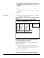
Version numbers
Display the curent scanner firmware versions.
• Select Version Numbers from the Configuration Items Window.
Configuration Items
Display Language
Measurement System
Date Format
Time Format
Set Time and Date
Confirmation Tone Volume
Confirmation Tones
Fixed Field Delimiter
Printer Messages
Version Numbers
Load scanner from laptop
Load laptop from scanner
2-12
Setting
DIGITAL SCIENCE Status
READY
English
Inch
1990/10/10
00:00
Soft
Enabled
Period (.)
Mode Configuration
Version #1
CPU: 00.00
DPC: 00.00
BCR: 00.00
OCR: 00.00
Laptop: 00.00
End Session
Strike any key
A-61074 April 1997
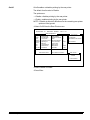
Load scanner from laptop
Used to upload a configuration file from diskette to the Scanner
5500/7500.
• Select Load Scanner from Laptop from the Configuration Items
window.
Configuration Items
Display Language
Measurement System
Date Format
Time Format
Set Time and Date
Confirmation Tone Volume
Confirmation Tones
Fixed Field Delimiter
Printer Messages
Version Numbers
Load scanner from laptop
Load laptop from scanner
Setting
DIGITAL SCIENCE Status
READY
English
Inch
1990/10/10
00:00
Soft
Enabled
Period (.)
Mode Configuration
End Session
The following window will appear:
Please Enter the Name of the
Configuration File to Send to DIGITAL SCIENCE.
c:\000000.cfg
File Name + <ENTER> = User Selected File
<ENTER> or Blank(s) + <ENTER> = Return to Previous Menu
<HOME> = Change Disk Drive (A: or C:)
Configuration File List:
• Enter the filename to upload and press Enter.
A-61074 April 1997
2-13
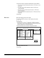
Load laptop from scanner
Used to download a configuration file from the Scanner 5500/7500
onto diskette. This is useful in creating configuration files which may
be transported to other Digital Science Scanners. This is also used
to create backup files. This option should be performed any time an
installation or setup change is completed.
• Select Load Laptop from Scanner from the Configuration Items
window.
Configuration Items
Display Language
Measurement System
Date Format
Time Format
Set Time and Date
Confirmation Tone Volume
Confirmation Tones
Fixed Field Delimiter
Printer Messages
Version Numbers
Load scanner from laptop
Load laptop from scanner
Setting
DIGITAL SCIENCE Status
READY
English
Inch
1990/10/10
00:00
Soft
Enabled
Period (.)
Mode Configuration
End Session
The following window will appear:
Please Enter the Name of the
Configuration File to Send to Laptop.
c:\000000.cfg
File Name + <ENTER> = User Selected File
<ENTER> or Blank(s) + <ENTER> = Return to Previous Menu
<HOME> = Change Disk Drive (A: or C:)
• Enter a filename (up to 8 characters long—no special characters
allowed, with a file extension of cfg).
• Press Enter.
2-14
A-61074 April 1997
3
Mode configuration
Accessing the Mode
Configuration Menu
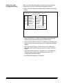
The following section describes how to access the Mode
Configuration menu, how to copy mode definitions from one mode to
another, how to select a mode for definition, and how to select each
item for definition.
Configuration Items
Display Language
Measurement System
Date Format
Time Format
Set Time and Date
Confirmation Tone Volume
Confirmation Tones
Fixed Field Delimiter
Printer Messages
Version Numbers
Load scanner from laptop
Load laptop from scanner
Setting
DIGITAL SCIENCE Status
READY
English
Inch
1990/10/10
00:00
Soft
Enabled
Period (.)
Mode Configuration
End Session
• Select Mode Configuration.
The Mode Configuration window will appear:
Mode Configuration
Define Mode 1
Define Mode 2
Define Mode 3
Define Mode 4
Define Mode 5
Define Mode 6
Define Mode 7
Define Mode 8
Define Mode 9
Define Mode 10
Define Mode 11
Define Mode 12
Define Mode 13
Define Mode 14
Define Mode 15
Define Mode 16
Define Mode 17
Define Mode 18
Mode to Mode Copy
End Session
Previous Menu
A-61074 April 1997
3-1
Mode-to-mode copying
A number of modes might have similar definitions. The mode to
mode copy feature allows you to fully define one mode and then
copy that mode definition to another mode, saving the time and effort
required to fully define each mode.
Perform the following steps to copy the definitions of one mode to
another mode:
Mode Configuration
Define Mode 1
Define Mode 2
Define Mode 3
Define Mode 4
Define Mode 5
Define Mode 6
Define Mode 7
Define Mode 8
Define Mode 9
Define Mode 10
Define Mode 11
Define Mode 12
Define Mode 13
Define Mode 14
Define Mode 15
Define Mode 16
Define Mode 17
Define Mode 18
Mode to Mode Copy
End Session
Previous Menu
• Select Mode to Mode Copy from the first Mode Configuration
window.
Mode to Mode Copy
Copy From
Mode:
Copy From Mode:
Define Mode 1
Define Mode 2
Define Mode 3
Define Mode 4
Define Mode 5
Define Mode 6
Define Mode 7
Define Mode 8
Define Mode 9
Define Mode 10
Define Mode 11
Define Mode 12
Define Mode 13
Define Mode 14
Define Mode 15
Define Mode 16
Define Mode 17
Define Mode 18
Previous Menu
3-2
A-61074 April 1997
• Select a mode which contains the definitions you wish to copy to
another mode from the Copy From Mode list.
Mode to Mode Copy
Copy From
Mode:
01
Copy From Mode:
Define Mode 1
Define Mode 2
Define Mode 3
Define Mode 4
Define Mode 5
Define Mode 6
Define Mode 7
Define Mode 8
Define Mode 9
Define Mode 10
Define Mode 11
Define Mode 12
Define Mode 13
Define Mode 14
Define Mode 15
Define Mode 16
Define Mode 17
Define Mode 18
--------------->
--------------->
--------------->
--------------->
--------------->
--------------->
--------------->
--------------->
--------------->
--------------->
--------------->
--------------->
--------------->
--------------->
--------------->
--------------->
--------------->
--------------->
Previous Menu
Copy To Mode:
Define Mode 1
Define Mode 2
Define Mode 3
Define Mode 4
Define Mode 5
Define Mode 6
Define Mode 7
Define Mode 8
Define Mode 9
Define Mode 10
Define Mode 11
Define Mode 12
Define Mode 13
Define Mode 14
Define Mode 15
Define Mode 16
Define Mode 17
Define Mode 18
Previous Menu
• Select the mode into which you wish to copy the previously
selected mode definitions from the Copy To Mode list.
Mode to Mode Copy
Copy From
Mode:
01
Copy From Mode:
Define Mode 1
Define Mode 2
Define Mode 3
Define Mode 4
Define Mode 5
Define Mode 6
Define Mode 7
Define Mode 8
Define Mode 9
Define Mode 10
Define Mode 11
Define Mode 12
Define Mode 13
Define Mode 14
Define Mode 15
Define Mode 16
Define Mode 17
Define Mode 18
Are you sure
you want to
do this?
All data in
the copied
mode will
be lost!
Previous Menu
Copy the Mode
Previous Menu
Copy To Mode:
Define Mode 1
Define Mode 2
Define Mode 3
Define Mode 4
Define Mode 5
Define Mode 6
Define Mode 7
Define Mode 8
Define Mode 9
Define Mode 10
Define Mode 11
Define Mode 12
Define Mode 13
Define Mode 14
Define Mode 15
Define Mode 16
Define Mode 17
Define Mode 18
Copy To
Mode:
02
Previous Menu
To copy the contents of the Copy From Mode to the Copy To Mode:
• Select the Copy the Mode option.
• Press Enter.
To cancel the Mode to Mode Copy:
• Select Previous Menu. You will be returned to the Mode
Configuration window.
A-61074 April 1997
3-3
Selecting a mode for
configuration
Perform the following steps to select a mode for configuration.
NOTE: Not all items available for definition need to be defined. If you
wish to allow an item to default or have performed a Mode to
Mode copy after fully defining the Copy From Mode, there is
no need to define each item.
Mode Configuration
Define Mode 1
Define Mode 2
Define Mode 3
Define Mode 4
Define Mode 5
Define Mode 6
Define Mode 7
Define Mode 8
Define Mode 9
Define Mode 10
Define Mode 11
Define Mode 12
Define Mode 13
Define Mode 14
Define Mode 15
Define Mode 16
Define Mode 17
Define Mode 18
Mode to Mode Copy
End Session
Previous Menu
• Select Define Mode x, where x is the number of the mode you wish
to configure.
The Mode Configuration window will appear:
Mode Number: 01
Mode Name: MODE01
Item #: 0.0
Mode Configuration
Single
6006
3111
Supprs
FthenR
None
Off
Off
NA NA
Index Format
IA Field Width
Level Rules
IA Display Format
Adjoining IA
Batching
Length Monitor
Skew Monitor
Footswitch
Patch Reader
COIN2 Port Select
OCR
Bar Code Reader
Printr Controller
Front Printer
Rear Printer
Mode Name
Overrides
Off
n/a
n/a
Off
Supprs
Off
Off
MODE0
No Sav
Save & End Session
Don't Save & End Session
Save & Prev Menu
Don't Save & Prev Menu
Mode configuration items may be selected from this window. A
detailed description of each item is provided in this section.
3-4
A-61074 April 1997
Index format
Index format defines the index format used by the application mode
selected.
Refer to Description 1: Index Formats for a description of the index
formats.
The default is mode dependent; the following list provides the
defaults for each mode:
Mode
Index Format
Mode 1
Single Level
Mode 2
Two Level Offset
Mode 3
Two Level
Mode 4
Three Level Offset
Mode 5
Three Level
Mode 6
Two Level
Mode 7
Two Level Offset
Mode 8
through
Mode 18
Three Level
The options are:
— Single Level
— Two Level
— Two Level Offset
— Three Level
— Three Level Offset.
• Select Index Format from the Mode Configuration window.
Mode Number: 01
Mode Name: MODE01
Item #: 1.0
Mode Configuration
Single
6006
3111
Supprs
FthenR
None
Off
Off
NA NA
Index Format
IA Field Width
Level Rules
IA Display Format
Adjoining IA
Batching
Length Monitor
Skew Monitor
Footswitch
Patch Reader
COIN2 Port Select
OCR
Bar Code Reader
Printr Controller
Front Printer
Rear Printer
Mode Name
Overrides
Off
n/a
n/a
Off
Supprs
Off
Off
MODE0
No Sav
Save & End Session
Don't Save & End Session
Save & Prev Menu
Don't Save & Prev Menu
Index Format
Single Level
Two Level
Two Level Offset
Three Level
Three Level Offset
Previous Menu
• Select the desired index format.
• Press Enter.
A-61074 April 1997
3-5
Description 1: Index Formats
There are five Index Format options available:
• Single Level
IA 1
(Level 1)
IA 2
(Level 1)
IA 3
(Level 1)
IA 4
(Level 1)
Whenever a document is assigned Level 1, the image address field associated
with Level 1 (Field A) is incremented.
• Two Level
IA 1.0
(Level 2)
IA 1.1
(Level 1)
IA 1.2
(Level 1)
IA 2.0
(Level 2)
Whenever a document is assigned Level 2, the image address field associated
with Level 2 (Field B) is incremented and the field associated with Level 1 (Field
A) is set to zero.
Whenever a document is assigned Level 1, the image address field associated
with Level 2 (Field B) is unchanged and the field associated with Level 1 (Field A)
is incremented.
• Two Level Offset
IA 1
(Level 2)
IA 1
(Level 1)
IA 1
(Level 1)
IA 2
(Level 2)
Whenever a document is assigned Level 2, the image address field associated
with Level 2 (Field B) is incremented.
Whenever a document is assigned Level 1, the image address is unchanged.
3-6
A-61074 April 1997
Description 1: Index Formats (continued)
• Three Level
IA 1.0.0
(Level 3)
IA 1.1.0
(Level 2)
IA 1.1.1
(Level 1)
IA 2.0.0
(Level 3)
Whenever a document is assigned Level 3, the image address field associated
with Level 3 (Field C) is incremented and the fields associated with Level 2
(Field B) and Level 1 (Field A) are set to zero.
Whenever a document is assigned Level 2, the image address field associated
with Level 3 (Field C) is unchanged, the field associated with Level 2 (Field B)
is incremented, and the field associated with Level 1 (Field A) is set to zero.
Whenever a document is assigned Level 1, the image address fields
associated with Level 3 (Field C) and Level 2 (Field B) are unchanged, and the
field associated with Level 1 (Field A) is incremented.
• Three Level Offset
IA 1.0
(Level 3)
IA 1.1
(Level 2)
IA 1.1
(Level 1)
IA 2.0
(Level 3)
Whenever a document is assigned Level 3, the image address field associated
with Level 3 (Field C) is incremented and the field associated with Level 2
(Field B) is set to zero.
Whenever a document is assigned Level 2, the image address field associated
with Level 3 (Field C) is unchanged, and the field associated with Level 2
(Field B) is incremented.
Whenever a document is assigned Level 1, the image address is unchanged.
A-61074 April 1997
3-7
IA Field width
IA Field width defines the image address (IA) field widths.
Refer to Description 2: Image Address Fields for a description of
proper field definitions.
• Select IA Field Width from the Mode Configuration window.
Mode Number: 01
Mode Name: MODE01
Item #: 2.0
Mode Configuration
Single
6006
3111
Supprs
FthenR
None
Off
Off
NA NA
Index Format
IA Field Width
Level Rules
IA Display Format
Adjoining IA
Batching
Length Monitor
Skew Monitor
Footswitch
Patch Reader
COIN2 Port Select
OCR
Bar Code Reader
Printr Controller
Front Printer
Rear Printer
Mode Name
Overrides
Off
n/a
n/a
Off
Supprs
Off
Off
MODE0
No Sav
Save & End Session
Don't Save & End Session
Save & Prev Menu
Don't Save & Prev Menu
Field
Field A
Field B
Field C
Fixed Field
Previous Menu
The following pages provide instructions on how to define the image
address field widths. When the field width definitions are complete,
you will automatically be returned to this window.
To close the Field menu:
• Select Previous Menu. Proceed to make any additional mode
configuration definitions.
3-8
A-61074 April 1997
Field A (Level 1)
Field A represents Level 1. Its value is incremented when a small
image mark is placed next to a document and/or a document is
assigned Level 1.
• Select Field A.
Refer to Description 3: Image Address Field Width Defaults for a
complete listing of the default values for each mode.
Mode Number: 01
Mode Name: MODE01
Item #: 2.x
Mode Configuration
Single
6006
3111
Supprs
FthenR
None
Off
Off
NA NA
Index Format
IA Field Width
Level Rules
IA Display Format
Adjoining IA
Batching
Length Monitor
Skew Monitor
Footswitch
Patch Reader
COIN2 Port Select
OCR
Bar Code Reader
Printr Controller
Front Printer
Rear Printer
Mode Name
Overrides
Off
n/a
n/a
Off
Supprs
Off
Off
MODE0
No Sav
Save & End Session
Don't Save & End Session
Save & Prev Menu
Don't Save & Prev Menu
Field
Field A
Field B
Field C
Fixed Field
Previous Menu
Select IA Field Width
0 1 2 3 4 5 6 7 8 9
• Select the desired IA field width (0–9) of Field A (Level 1).
• Press Enter.
A-61074 April 1997
3-9
Field B (Level 2)
Field B represents Level 2. Its value is incremented when a medium
image mark is placed next to a document and/or a document is
assigned Level 2.
• Select Field B.
Refer to Description 3: Image Address Field Width Defaults for a
complete listing of the default values for each mode.
Mode Number: 01
Mode Name: MODE01
Item #: 2.x
Mode Configuration
Single
6006
3111
Supprs
FthenR
None
Off
Off
NA NA
Index Format
IA Field Width
Level Rules
IA Display Format
Adjoining IA
Batching
Length Monitor
Skew Monitor
Footswitch
Patch Reader
COIN2 Port Select
OCR
Bar Code Reader
Printr Controller
Front Printer
Rear Printer
Mode Name
Overrides
Off
n/a
n/a
Off
Supprs
Off
Off
MODE0
No Sav
Save & End Session
Don't Save & End Session
Save & Prev Menu
Don't Save & Prev Menu
Field
Field A
Field B
Field C
Fixed Field
Previous Menu
Select IA Field Width
0 1 2 3 4 5 6 7 8 9
• Select the desired field width (0–9) of Field B (Level 2).
• Press Enter.
3-10
A-61074 April 1997
Field C (Level 3)
Field C represents Level 3. Its value is incremented when a large
image mark is placed next to a document and/or a document is
assigned Level 3.
• Select Field C.
Refer to Description 3: Image Address Field Width Defaults for a
complete listing of the default values for each mode.
Mode Number: 01
Mode Name: MODE01
Item #: 2.x
Mode Configuration
Single
6006
3111
Supprs
FthenR
None
Off
Off
NA NA
Index Format
IA Field Width
Level Rules
IA Display Format
Adjoining IA
Batching
Length Monitor
Skew Monitor
Footswitch
Patch Reader
COIN2 Port Select
OCR
Bar Code Reader
Printr Controller
Front Printer
Rear Printer
Mode Name
Overrides
Off
n/a
n/a
Off
Supprs
Off
Off
MODE0
No Sav
Save & End Session
Don't Save & End Session
Save & Prev Menu
Don't Save & Prev Menu
Field
Field A
Field B
Field C
Fixed Field
Previous Menu
Select IA Field Width
0 1 2 3 4 5 6 7 8 9
• Select the desired IA field width (0–9) of Field C (Level 3).
• Press Enter.
A-61074 April 1997
3-11
Fixed field
Fixed field contains fixed information, typically the date.
• Select Fixed Field.
Refer to Description 3: Image Address Field Width Defaults for a
complete listing of the default values for each mode.
Mode Number: 01
Mode Name: MODE01
Item #: 2.x
Mode Configuration
Single
6006
3111
Supprs
FthenR
None
Off
Off
NA NA
Index Format
IA Field Width
Level Rules
IA Display Format
Adjoining IA
Batching
Length Monitor
Skew Monitor
Footswitch
Patch Reader
COIN2 Port Select
OCR
Bar Code Reader
Printr Controller
Front Printer
Rear Printer
Mode Name
Overrides
Off
n/a
n/a
Off
Supprs
Off
Off
MODE0
No Sav
Save & End Session
Don't Save & End Session
Save & Prev Menu
Don't Save & Prev Menu
Field
Field A
Field B
Field C
Fixed Field
Previous Menu
Select IA Field Width
0 1 2 3 4 5 6 7 8 9
• Select the desired IA field width (0–9) of the Fixed Field.
• Press Enter.
3-12
A-61074 April 1997
Description 2: Image Address Fields
An image address is a unique identifier assigned to each individual document by the
Scanner 5500 or 7500.
An image address may contain up to 15 characters; consisting of a maximum of
12 digits and a maximum of 3 delimiters.
Four fields must be defined:
• Field A represents Level 1. Its value is incremented when a small image mark is
placed next to a document and/or a document is assigned Level 1.
• Field B represents Level 2. Its value is incremented when a medium image mark is
placed next to a document and/or a document is assigned Level 2.
• Field C represents Level 3. Its value is incremented when a large image mark is
placed next to a document and/or a document is assigned Level 3.
• Fixed Field contains fixed information; typically, the date.
Example:
0301.02.001.000
where:
Field A contains 000
Field B contains 001
Field C contains 02
Fixed Field contains 0301
The image address field lengths are dependent upon the index format chosen earlier:
• Single Level (Example: FFF.AAA)
Field A is defined as having a field length greater than zero (1–9).
Field B is defined as having a field length of zero (0).
Field C is defined as having a field length of zero (0).
Fixed Field may be defined, if desired (0–9).
• Two Level (Example: FFF.BBB.AAA)
Field A is defined as having a field length greater than zero (1–9).
Field B is defined as having a field length greater than zero (1–9).
Field C is defined as having a field length of zero (0).
Fixed Field may be defined, if desired (0–9).
• Two Level Offset (Example: FFF.BBB)
Field A is defined as having a field length of zero (0).
Field B is defined as having a field length greater than zero (1–9).
Field C is defined as having a field length of zero (0).
Fixed Field may be defined, if desired (0–9).
• Three Level (Example: FFF.CCC.BBB.AAA)
Field A is defined as having a field length greater than zero (1–9).
Field B is defined as having a field length greater than zero (1–9).
Field C is defined as having a field length greater than zero (1–9).
Fixed Field may be defined, if desired (0–9).
• Three Level Offset (Example: FFF.CCC.BBB)
Field A is defined as having a field length of zero (0).
Field B is defined as having a field length greater than zero (1–9).
Field C is defined as having a field length greater than zero (1–9).
Fixed Field may be defined, if desired (0–9).
A-61074 April 1997
3-13
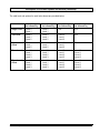
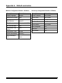
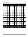
Description 3: Image Address Field Width Defaults
The default field widths for each mode are provided below:
Fixed
Field
Field C
Level 3
Field B
Level 2
Field A
Level 1
Example
Mode 1
6
0
0
6
FFFFFF.AAAAAA
Mode 2
6
0
6
0
FFFFFF.BBBBBB
Mode 3
6
0
3
3
FFFFFF.BBB.AAA
Mode 4
6
3
3
0
FFFFFF.CCC.BBB
Mode 5
4
2
3
3
FFFF.CC.BBB.AAA
Mode 6
6
0
4
2
FFFFFF.BBBB.AA
Mode 7
6
0
6
0
FFFFFF.BBBBBB
Mode 8
4
2
3
3
FFFF.CC.BBB.AAA
Mode 9
4
2
3
3
FFFF.CC.BBB.AAA
Mode 10
4
2
3
3
FFFF.CC.BBB.AAA
Mode 11
4
2
3
3
FFFF.CC.BBB.AAA
Mode 12
4
2
3
3
FFFF.CC.BBB.AAA
Mode 13
4
2
3
3
FFFF.CC.BBB.AAA
Mode 14
4
2
3
3
FFFF.CC.BBB.AAA
Mode 15
4
2
3
3
FFFF.CC.BBB.AAA
Mode 16
4
2
3
3
FFFF.CC.BBB.AAA
Mode 17
4
2
3
3
FFFF.CC.BBB.AAA
Mode 18
4
2
3
3
FFFF.CC.BBB.AAA
3-14
A-61074 April 1997
Level rules
Level rules define the level of a document based upon the level of
the previous document. These definitions are used as defaults when
the document level is not determined by another method (i.e.,
footswitch, level key, etc).
• Select Level Rules from the Mode Configuration window.
Mode Number: 01
Mode Name: MODE01
Item #: 3.0
Mode Configuration
Single
6006
3111
Supprs
FthenR
None
Off
Off
NA NA
Index Format
IA Field Width
Level Rules
IA Display Format
Adjoining IA
Batching
Length Monitor
Skew Monitor
Footswitch
Patch Reader
COIN2 Port Select
OCR
Bar Code Reader
Printr Controller
Front Printer
Rear Printer
Mode Name
Overrides
Off
n/a
n/a
Off
Supprs
Off
Off
MODE0
No Sav
Save & End Session
Don't Save & End Session
Save & Prev Menu
Don't Save & Prev Menu
Level
Level 0
Level 1
Level 2
Level 3
Previous Menu
The following pages provide instructions on how to define the level
rules, based upon the definition made using the Index Format
option. When the level rule definitions are complete, you will
automatically be returned to this window.
To close the Level menu:
• Select Previous Menu. Proceed to make any additional mode
configuration definitions.
A-61074 April 1997
3-15
Level to follow level 0
NOTE: This menu option is a valid selection when using any of the
available index formats defined using the Index Format
option.
• Select Level 0.
Refer to Description 4: Level Rule Options and Defaults for a
complete listing of the valid selections and default values for each
mode.
Mode Number: 01
Mode Name: MODE01
Item #: 3.1
Mode Configuration
Single
6006
3111
Supprs
FthenR
None
Off
Off
NA NA
Index Format
IA Field Width
Level Rules
IA Display Format
Adjoining IA
Batching
Length Monitor
Skew Monitor
Footswitch
Patch Reader
COIN2 Port Select
OCR
Bar Code Reader
Printr Controller
Front Printer
Rear Printer
Mode Name
Overrides
Off
n/a
n/a
Off
Supprs
Off
Off
MODE0
No Sav
Save & End Session
Don't Save & End Session
Save & Prev Menu
Don't Save & Prev Menu
Level
Level 0
Level 1
Level 2
Level 3
Previous Menu
Lv To Follow Lv 0
Level 0
Level 1
Level 2
Level 3
Previous Menu
• Select the desired document level from the Lv To Follow Lv 0
menu.
• Press Enter.
— If the document level selected is valid, the Lv To Follow Lv 0
menu will close and another level may be chosen from the Level
menu.
— If the document level selected is not valid, based upon the
Index Format already selected, an error message, such as; Bad
Level (Level 2) for a Single-Level system. Press <ENTER>
key will appear.
To clear the message:
• Press Enter and select a valid document level.
3-16
A-61074 April 1997
Level to follow level 1
NOTE: This menu option is a valid selection when using any of the
available index formats defined using the Index Format
option.
• Select Level 1.
Refer to Description 4: Level Rule Options and Defaults for a
complete listing of the valid selections and default values for each
mode.
Mode Number: 01
Mode Name: MODE01
Item #: 3.2
Mode Configuration
Single
6006
3111
Supprs
FthenR
None
Off
Off
NA NA
Index Format
IA Field Width
Level Rules
IA Display Format
Adjoining IA
Batching
Length Monitor
Skew Monitor
Footswitch
Patch Reader
COIN2 Port Select
OCR
Bar Code Reader
Printr Controller
Front Printer
Rear Printer
Mode Name
Overrides
Off
n/a
n/a
Off
Supprs
Off
Off
MODE0
No Sav
Save & End Session
Don't Save & End Session
Save & Prev Menu
Don't Save & Prev Menu
Level
Level 0
Level 1
Level 2
Level 3
Previous Menu
Lv To Follow Lv 1
Level 0
Level 1
Level 2
Level 3
Previous Menu
• Select the desired document level from the Lv To Follow Lv 1
menu.
• Press Enter.
— If the document level selected is valid, the Lv To Follow Lv 1
menu will close and another level may be chosen from the Level
menu.
— If the document level selected is not valid, based upon the
Index Format already selected, an error message, such as; Bad
Level (Level 2) for a Single-Level system. Press <ENTER>
key will appear.
To clear the message:
• Press Enter and select a valid document level.
A-61074 April 1997
3-17
Level to follow level 2
NOTE: This menu option is a valid selection only when using any of
the two-level (two level or two level offset) or three-level
(three level or three level offset) index formats defined using
the Index Format option.
• Select Level 2.
Refer to Description 4: Level Rule Options and Defaults for a
complete listing of the valid selections and default values for each
mode.
Mode Number: 01
Mode Name: MODE01
Item #: 3.3
Mode Configuration
Single
6006
3111
Supprs
FthenR
None
Off
Off
NA NA
Index Format
IA Field Width
Level Rules
IA Display Format
Adjoining IA
Batching
Length Monitor
Skew Monitor
Footswitch
Patch Reader
COIN2 Port Select
OCR
Bar Code Reader
Printr Controller
Front Printer
Rear Printer
Mode Name
Overrides
Off
n/a
n/a
Off
Supprs
Off
Off
MODE0
No Sav
Save & End Session
Don't Save & End Session
Save & Prev Menu
Don't Save & Prev Menu
Level
Level 0
Level 1
Level 2
Level 3
Previous Menu
Lv To Follow Lv 2
Level 0
Level 1
Level 2
Level 3
Previous Menu
• Select the desired document level from the Lv To Follow Lv 2
menu.
• Press Enter.
— If the document level selected is valid, the Lv To Follow Lv 2
menu will close and another level may be chosen from the Level
menu.
— If the document level selected is not valid, based upon the
Index Format already selected, an error message, such as; Bad
Level (Level 3) for a Single-Level system. Press <ENTER>
key will appear.
To clear the message:
• Press Enter and select a valid document level.
3-18
A-61074 April 1997
Level to follow level 3
NOTE: This menu option is a valid selection only when using any of
the three-level (three level or three level offset) index formats
defined using the Index Format option.
• Select Level 3.
Refer to Description 4: Level Rule Options and Defaults for a
complete listing of the valid selections and default values for each
mode.
Mode Number: 01
Mode Name: MODE01
Item #: 3.4
Mode Configuration
Single
6006
3111
Supprs
FthenR
None
Off
Off
NA NA
Index Format
IA Field Width
Level Rules
IA Display Format
Adjoining IA
Batching
Length Monitor
Skew Monitor
Footswitch
Patch Reader
COIN2 Port Select
OCR
Bar Code Reader
Printr Controller
Front Printer
Rear Printer
Mode Name
Overrides
Off
n/a
n/a
Off
Supprs
Off
Off
MODE0
No Sav
Save & End Session
Don't Save & End Session
Save & Prev Menu
Don't Save & Prev Menu
Level
Level 0
Level 1
Level 2
Level 3
Previous Menu
Lv To Follow Lv 3
Level 0
Level 1
Level 2
Level 3
Previous Menu
• Select the desired document level from the Lv To Follow Lv 3
menu.
• Press Enter.
— If the document level selected is valid, the Lv To Follow Lv 3
menu will close and another level may be chosen from the Level
menu.
— If the document level selected is not valid, based upon the
Index Format already selected, an error message, such as; Bad
Level (Level 2) for a Single-Level system. Press <ENTER>
key will appear.
To clear the message:
• Press Enter and select a valid document level.
A-61074 April 1997
3-19
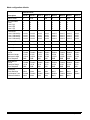
Description 4: Level Rule Options and Defaults
The default level rules for each mode are provided below:
Level 0
is followed by
Level 1
is followed by
Level 2
is followed by
Level 3
is followed by
Mode 1
Level 1
Level 1
Level 1
Level 3
Mode 2
Level 2
Level 1
Level 2
Level 3
Mode 3
Level 2
Level 1
Level 2
Level 3
Mode 4
Level 3
Level 1
Level 2
Level 2
Mode 5
Level 2
Level 1
Level 2
Level 2
Mode 6
Level 2
Level 2
Level 2
Level 3
Mode 7
Level 2
Level 2
Level 2
Level 3
Mode 8
Level 2
Level 1
Level 1
Level 2
Mode 9
Level 2
Level 1
Level 1
Level 2
Mode 10
Level 2
Level 1
Level 1
Level 2
Mode 11
Level 2
Level 1
Level 1
Level 2
Mode 12
Level 2
Level 1
Level 1
Level 2
Mode 13
Level 2
Level 1
Level 1
Level 2
Mode 14
Level 2
Level 1
Level 1
Level 2
Mode 15
Level 2
Level 1
Level 1
Level 2
Mode 16
Level 2
Level 1
Level 1
Level 2
Mode 17
Level 2
Level 1
Level 1
Level 2
Mode 18
Level 2
Level 1
Level 1
Level 2
3-20
A-61074 April 1997
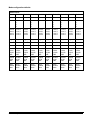
Description 4: Level Rule Options and Defaults (continued)
The valid level rule options for each index format are provided below:
Level 0 may
be followed by
Level 1 may
be followed by
Level 2 may
be followed by
Level 3 may
be followed by
Single Level
Level 0
Level 1
Level 0
Level 1
n/a
n/a
Two Level
Level 0
Level 1
Level 2
Level 0
Level 1
Level 2
Level 0
Level 1
Level 2
n/a
Two Level
Offset
Level 0
Level 1
Level 2
Level 0
Level 1
Level 2
Level 0
Level 1
Level 2
n/a
Three Level
Level 0
Level 1
Level 2
Level 3
Level 0
Level 1
Level 2
Level 3
Level 0
Level 1
Level 2
Level 3
Level 0
Level 1
Level 2
Level 3
Three Level
Offset
Level 0
Level 1
Level 2
Level 3
Level 0
Level 1
Level 2
Level 3
Level 0
Level 1
Level 2
Level 3
Level 0
Level 1
Level 2
Level 3
A-61074 April 1997
3-21
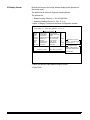
IA Display format
Defines the format of the image address display which appears on
the control panel.
The default for all modes is Suppress Leading Zeroes.
The options are:
— Display Leading Zeroes (i.e., 001.002.003.004)
— Suppress Leading Zeroes (i.e., 001. 2. 3. 4)
• Select IA Display Format from the Mode Configuration window.
Mode Number: 01
Mode Name: MODE01
Item #: 4.0
Mode Configuration
Single
6006
3111
Supprs
FthenR
None
Off
Off
NA NA
Index Format
IA Field Width
Level Rules
IA Display Format
Adjoining IA
Batching
Length Monitor
Skew Monitor
Footswitch
Patch Reader
COIN2 Port Select
OCR
Bar Code Reader
Printr Controller
Front Printer
Rear Printer
Mode Name
Overrides
Off
n/a
n/a
Off
Supprs
Off
Off
MODE0
No Sav
Save & End Session
Don't Save & End Session
Save & Prev Menu
Don't Save & Prev Menu
Examples of Formats
Display: 001.002.003.004
Suppress: 001. 2. 3. 4
IA Display Format
Display Leading Zeroes
Suppress Leading Zeroes
Previous Menu
• Select the desired image address display format.
• Press Enter.
3-22
A-61074 April 1997
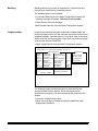
Adjoining IA
Defines the image address assigned to the rear side image of a
document scanned in duplex mode.
The default for all modes is Front then Rear.
The options are:
— Sequential—indicates that the rear side image of a document
scanned in duplex mode will be assigned a unique image
address—incremented from the image address assigned to the
front side image.
— Front then Rear—indicates that the rear side image of a
document scanned in duplex mode will be assigned the same
image address that the front side image was assigned.
• Select Adjoining IA from the Mode Configuration window.
Mode Number: 01
Mode Name: MODE01
Item #: 5.0
Mode Configuration
Single
6006
3111
Supprs
FthenR
None
Off
Off
NA NA
Index Format
IA Field Width
Level Rules
IA Display Format
Adjoining IA
Batching
Length Monitor
Skew Monitor
Footswitch
Patch Reader
COIN2 Port Select
OCR
Bar Code Reader
Printr Controller
Front Printer
Rear Printer
Mode Name
Overrides
Off
n/a
n/a
Off
Supprs
Off
Off
MODE0
No Sav
Save & End Session
Don't Save & End Session
Save & Prev Menu
Don't Save & Prev Menu
Adjoining IA
Sequential
Front then Rear
Previous Menu
• Select the desired adjoining image address assignment scheme.
• Press Enter.
A-61074 April 1997
3-23
Batching
Batching defines the number of documents of a specified level to
process prior to performing a predefined action.
The batching option is not available.
• If you select Batching from the Mode Configuration window, the
following message will appear: Selection is not available.
• Press Enter to close the message.
• Make another selection from the Mode Configuration window.
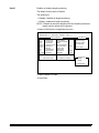
Length monitor
Length monitor defines the options required to enable/disable the
document length monitor, set the minimum and maximum document
lengths acceptable, and what action is to be taken when a document
shorter than the minimum length or longer than the maximum length
is fed into the Scanner 5500/7500.
• Select Length Monitor from the Mode Configuration window.
Mode Number: 01
Mode Name: MODE01
Item #: 7.0
Mode Configuration
Single
6006
3111
Supprs
FthenR
None
Off
Off
NA NA
Index Format
IA Field Width
Level Rules
IA Display Format
Adjoining IA
Batching
Length Monitor
Skew Monitor
Footswitch
Patch Reader
COIN2 Port Select
OCR
Bar Code Reader
Printr Controller
Front Printer
Rear Printer
Mode Name
Overrides
Off
n/a
n/a
Off
Supprs
Off
Off
MODE0
No Sav
Save & End Session
Don't Save & End Session
Save & Prev Menu
Don't Save & Prev Menu
Length Monitor
On/Off
Minimum Length
Maximum Length
Error Response
Previous Menu
The following pages provide instructions on how to define the
document length monitor options. When the length monitor
definitions are complete, you will automatically be returned to this
window.
To close the Length Monitor menu:
• Select Previous Menu. Proceed to make any additional mode
configuration definitions.
3-24
A-61074 April 1997
On/off
Enables or disables length monitoring.
The default for all modes is Disable.
The options are:
— Disable—disables all length monitoring.
— Enable—enables all length monitoring.
NOTE: If Disable is selected, definitions for the remaining document
length monitor options will be ignored.
• Select On/Off from the Length Monitor menu.
Mode Number: 01
Mode Name: MODE01
Item #: 7.1
Mode Configuration
Single
6006
3111
Supprs
FthenR
None
Off
Off
NA NA
Index Format
IA Field Width
Level Rules
IA Display Format
Adjoining IA
Batching
Length Monitor
Skew Monitor
Footswitch
Patch Reader
COIN2 Port Select
OCR
Bar Code Reader
Printr Controller
Front Printer
Rear Printer
Mode Name
Overrides
Off
n/a
n/a
Off
Supprs
Off
Off
MODE0
No Sav
Save & End Session
Don't Save & End Session
Save & Prev Menu
Don't Save & Prev Menu
Length Monitor
On/Off
Minimum Length
Maximum Length
Error Response
Previous Menu
Length Monitor
Disable
Enable
Previous Menu
• Select Disable or Enable.
• Press Enter.
A-61074 April 1997
3-25
Minimum length
Defines the minimum document length accepted.
The default for all modes is 2.500 inches / 64 mm.
The options are:
— Within the range of 2.500 inches / 64 mm minimum to
20.000 inches / 508 mm maximum.
• Select Minimum Length from the Length Monitor menu.
Mode Number: 01
Mode Name: MODE01
Item #: 7.2
Mode Configuration
Single
6006
3111
Supprs
FthenR
None
Off
Off
NA NA
Index Format
IA Field Width
Level Rules
IA Display Format
Adjoining IA
Batching
Length Monitor
Skew Monitor
Footswitch
Patch Reader
COIN2 Port Select
OCR
Bar Code Reader
Printr Controller
Front Printer
Rear Printer
Mode Name
Overrides
Off
n/a
n/a
Off
Supprs
Off
Off
MODE0
No Sav
Save & End Session
Don't Save & End Session
Save & Prev Menu
Don't Save & Prev Menu
Use Arrow Keys to Set
Increase value by 0.125 inch or 1mm
Decrease value by 0.125 inch or 1mm
Increase value by 1.250 inch or 20mm
Decrease value by 1.250 inch or 20mm
Length Monitor
On/Off
Minimum Length
Maximum Length
Error Response
Previous Menu
Enter Min. Doc. Length
Range: 2.500 . . . 20.000
2.500
• Enter the desired minimum document length using the numeric
keys;
or
• Use the arrow keys to increase or decrease the current minimum
document length to the desired minimum document length:
— The left arrow key will decrease the value in 0.125 inch or 1 mm
increments.
— The right arrow key will increase the value in 0.125 inch or 1 mm
increments.
— The down arrow key will decrease the value in 1.250 inch or
20 mm increments.
— The up arrow key will increase the value in 1.250 inch or 20 mm
increments.
• Press Enter.
3-26
A-61074 April 1997
Maximum length
Defines the maximum document length accepted.
The default for all modes is 13.000 inches / 330 mm.
The options are:
— Within the range of 2.500 inches / 64 mm minimum to
20.000 inches / 508 mm maximum.
• Select Maximum Length from the Length Monitor menu.
Mode Number: 01
Mode Name: MODE01
Item #: 7.3
Mode Configuration
Single
6006
3111
Supprs
FthenR
None
Off
Off
NA NA
Index Format
IA Field Width
Level Rules
IA Display Format
Adjoining IA
Batching
Length Monitor
Skew Monitor
Footswitch
Patch Reader
COIN2 Port Select
OCR
Bar Code Reader
Printr Controller
Front Printer
Rear Printer
Mode Name
Overrides
Off
n/a
n/a
Off
Supprs
Off
Off
MODE0
No Sav
Save & End Session
Don't Save & End Session
Save & Prev Menu
Don't Save & Prev Menu
Use Arrow Keys to Set
Increase value by 0.125 inch or 1mm
Decrease value by 0.125 inch or 1mm
Increase value by 1.250 inch or 20mm
Decrease value by 1.250 inch or 20mm
Length Monitor
On/Off
Minimum Length
Maximum Length
Error Response
Previous Menu
Enter Max. Doc. Length
Range: 2.500 . . . 20.000
13.000
• Enter the desired maximum document length using the numeric
keys;
or
• Use the arrow keys to increase or decrease the current minimum
document length to the desired maximum document length:
— The left arrow key will decrease the value in 0.125 inch or 1 mm
increments.
— The right arrow key will increase the value in 0.125 inch or
1 mm increments.
— The down arrow key will decrease the value in 1.250 inch or
20 mm increments.
— The up arrow key will increase the value in 1.250 inch or 20 mm
increments.
• Press Enter.
NOTE: A maximum document length of 17.000 inches / 432 mm or
less is recommended based upon the capacity of the exit
hopper.
A-61074 April 1997
3-27
Error response
Error response defines the action taken when a document shorter
than the minimum length or longer than the maximum length is fed
into the Scanner 5500/7500.
The default for all modes is Display and Beep.
The options are:
— Display Error Message—results in an error message appearing
on the Operator Control Panel (E106–Doc Length Monitor
Warning).
— Display and Beep—results in an error message appearing on the
Operator Control Panel (E106–Doc Length Monitor Warning),
accompanied by an error tone.
— Stop, Display, & Beep—which results in the transport shutting
down, and an error message appearing on the Operator Control
Panel (E214–Re-Scan-Length Monitr Er), accompanied by an
error tone.
• Select Error Response from the Length Monitor menu.
Mode Number: 01
Mode Name: MODE01
Item #: 7.4
Mode Configuration
Single
6006
3111
Supprs
FthenR
None
Off
Off
NA NA
Index Format
IA Field Width
Level Rules
IA Display Format
Adjoining IA
Batching
Length Monitor
Skew Monitor
Footswitch
Patch Reader
COIN2 Port Select
OCR
Bar Code Reader
Printr Controller
Front Printer
Rear Printer
Mode Name
Overrides
Off
n/a
n/a
Off
Supprs
Off
Off
MODE0
No Sav
Save & End Session
Don't Save & End Session
Save & Prev Menu
Don't Save & Prev Menu
Length Monitor
On/Off
Minimum Length
Maximum Length
Error Response
Previous Menu
Error Response
Display Error Message
Display and Beep
Stop, Display, & Beep
Previous Menu
• Select the desired error response.
• Press Enter.
3-28
A-61074 April 1997
Skew monitor
Skew monitor defines the options required to enable/disable the
document skew monitor, set the amount of acceptable document
skew, and what action is to be taken when document skew is
detected.
NOTE: In order for the skew monitor to operate correctly, the
following conditions must be true:
— The amount of skew must be less than 30 degrees.
— The document(s) must be center-fed.
— The document(s) fed must be at least 3 inches / 75 mm
wide.
• Select Skew Monitor from the Mode Configuration window.
Mode Number: 01
Mode Name: MODE01
Item #: 8.0
Mode Configuration
Single
6006
3111
Supprs
FthenR
None
Off
Off
NA NA
Index Format
IA Field Width
Level Rules
IA Display Format
Adjoining IA
Batching
Length Monitor
Skew Monitor
Footswitch
Patch Reader
COIN2 Port Select
OCR
Bar Code Reader
Printr Controller
Front Printer
Rear Printer
Mode Name
Overrides
Off
n/a
n/a
Off
Supprs
Off
Off
MODE0
No Sav
Save & End Session
Don't Save & End Session
Save & Prev Menu
Don't Save & Prev Menu
Skew Monitor
On/Off
Detection Range
Error Response
Previous Menu
The following pages provide instructions on how to define the
document skew monitor options. When the skew monitor definitions
are complete, you will automatically be returned to this
window.
To close the Skew Monitor menu:
• Select Previous Menu. Proceed to make any additional mode
configuration definitions.
A-61074 April 1997
3-29
On/off
The on/off enables or disables skew monitoring.
The default for all modes is Disable.
The options are:
— Disable—disables all skew monitoring.
— Enable—enables all skew monitoring.
NOTE: If Disable is selected, definitions for the remaining document
skew monitor options will be ignored.
• Select On/Off from the Skew Monitor menu.
Mode Number: 01
Mode Name: MODE01
Item #: 8.1
Mode Configuration
Single
6006
3111
Supprs
FthenR
None
Off
Off
NA NA
Index Format
IA Field Width
Level Rules
IA Display Format
Adjoining IA
Batching
Length Monitor
Skew Monitor
Footswitch
Patch Reader
COIN2 Port Select
OCR
Bar Code Reader
Printr Controller
Front Printer
Rear Printer
Mode Name
Overrides
Off
n/a
n/a
Off
Supprs
Off
Off
MODE0
No Sav
Save & End Session
Don't Save & End Session
Save & Prev Menu
Don't Save & Prev Menu
Skew Monitor
On/Off
Detection Range
Error Response
Previous Menu
Skew Monitor
Disable
Enable
Previous Menu
• Select Disable or Enable.
• Press Enter.
3-30
A-61074 April 1997
Detection range
Detection range defines the amount of tolerable skew.
The default for all modes is 10–30 degrees.
The options are:
— 5–30 degrees—results in an error being reported if the amount of
document skew is between 5 and 30 degrees.
— 10–30 degrees—results in an error being reported if the amount
of document skew is between 10 and 30 degrees.
• Select Detection Range from the Skew Monitor menu.
Mode Number: 01
Mode Name: MODE01
Item #: 8.2
Mode Configuration
Single
6006
3111
Supprs
FthenR
None
Off
Off
NA NA
Index Format
IA Field Width
Level Rules
IA Display Format
Adjoining IA
Batching
Length Monitor
Skew Monitor
Footswitch
Patch Reader
COIN2 Port Select
OCR
Bar Code Reader
Printr Controller
Front Printer
Rear Printer
Mode Name
Overrides
Off
n/a
n/a
Off
Supprs
Off
Off
MODE0
No Sav
Save & End Session
Don't Save & End Session
Save & Prev Menu
Don't Save & Prev Menu
Skew Monitor
On/Off
Detection Range
Error Response
Previous Menu
Detection Range
5 – 30 Degrees
10 – 30 Degrees
Previous Menu
• Select the desired skew detection range.
• Press Enter.
A-61074 April 1997
3-31
Error response
Error response defines the action taken when a document skew is
detected.
The default for all modes is Display and Beep.
The options are:
— Display Error Message—results in an error message appearing
on the Operator Control Panel (E107–Doc Skew Monitor
Warning).
— Display and Beep—results in an error message appearing on the
Operator Control Panel (E107–Doc Skew Monitor Warning),
accompanied by an error tone.
— Stop, Display, & Beep—results in the transport shutting down,
and an error message appearing on the Operator Control Panel
(E204–Re-Scan-Skew Moniotr Er), accompanied by an error tone.
• Select Error Response from the Skew Monitor menu.
Mode Number: 01
Mode Name: MODE01
Item #: 8.3
Mode Configuration
Single
6006
3111
Supprs
FthenR
None
Off
Off
NA NA
Index Format
IA Field Width
Level Rules
IA Display Format
Adjoining IA
Batching
Length Monitor
Skew Monitor
Footswitch
Patch Reader
COIN2 Port Select
OCR
Bar Code Reader
Printr Controller
Front Printer
Rear Printer
Mode Name
Overrides
Off
n/a
n/a
Off
Supprs
Off
Off
MODE0
No Sav
Save & End Session
Don't Save & End Session
Save & Prev Menu
Don't Save & Prev Menu
Skew Monitor
On/Off
Detection Range
Error Response
Previous Menu
Error Response
Display Error Message
Display and Beep
Stop, Display, & Beep
Previous Menu
• Select the desired error response.
• Press Enter.
3-32
A-61074 April 1997
Footswitch
Footswitch defines the options required when using the footswitch
accessory.
• Select Footswitch from the Mode Configuration window.
Mode Number: 01
Mode Name: MODE01
Item #: 9.0
Mode Configuration
Single
6006
3111
Supprs
FthenR
None
Off
Off
NA NA
Index Format
IA Field Width
Level Rules
IA Display Format
Adjoining IA
Batching
Length Monitor
Skew Monitor
Footswitch
Patch Reader
COIN2 Port Select
OCR
Bar Code Reader
Printr Controller
Front Printer
Rear Printer
Mode Name
Overrides
Off
n/a
n/a
Off
Supprs
Off
Off
MODE0
No Sav
Save & End Session
Don't Save & End Session
Save & Prev Menu
Don't Save & Prev Menu
Footswitch
Press Definition
Confirmation Tone
Release Definition
Previous Menu
The following pages provide instructions on how to define the
footswitch options. When the footswitch definitions are complete,
you will automatically be returned to this window.
To close the Footswitch menu:
• Select Previous Menu. Proceed to make any additional mode
configuration definitions.
A-61074 April 1997
3-33
Press definition
Press definition defines the action which is taken when the
footswitch is pressed.
The default for all modes is No Action.
The options are:
— Level 0—document Level 0 will be assigned to the next
document.
— Level 1—document Level 1 will be assigned to the next
document.
— Level 2—document Level 2 will be assigned to the next
document.
— Level 3—document Level 3 will be assigned to the next
document.
— Increment—results in the next document being assigned the next
document level, based upon the Level Rules established using
the Level Rules option.
— No Action—results in no action taking place when the footswitch
is pressed.
• Select Press Definition from the Footswitch menu.
Mode Number: 01
Mode Name: MODE01
Item #: 9.1
Mode Configuration
Single
6006
3111
Supprs
FthenR
None
Off
Off
NA NA
Index Format
IA Field Width
Level Rules
IA Display Format
Adjoining IA
Batching
Length Monitor
Skew Monitor
Footswitch
Patch Reader
COIN2 Port Select
OCR
Bar Code Reader
Printr Controller
Front Printer
Rear Printer
Mode Name
Overrides
Off
n/a
n/a
Off
Supprs
Off
Off
MODE0
No Sav
Save & End Session
Don't Save & End Session
Save & Prev Menu
Don't Save & Prev Menu
Footswitch
Press Definition
Confirmation Tone
Release Definition
Previous Menu
Press Definition
Level 0
Level 1
Level 2
Level 3
Increment
No Action
Previous Menu
• Select the desired action.
• Press Enter.
3-34
A-61074 April 1997
Confirmation tone
Confirmation tone enables or disables the Confirmation Tone which
sounds when the Footswitch is pressed or released.
The default for all modes is Disable.
The options are:
— Disable—results in no tone sounding when the footswitch is
pressed or released.
— Enable—results in a tone sounding when the footswitch is
pressed and released.
• Select Confirmation Tone from the Footswitch menu.
Mode Number: 01
Mode Name: MODE01
Item #: 9.2
Mode Configuration
Single
6006
3111
Supprs
FthenR
None
Off
Off
NA NA
Index Format
IA Field Width
Level Rules
IA Display Format
Adjoining IA
Batching
Length Monitor
Skew Monitor
Footswitch
Patch Reader
COIN2 Port Select
OCR
Bar Code Reader
Printr Controller
Front Printer
Rear Printer
Mode Name
Overrides
Off
n/a
n/a
Off
Supprs
Off
Off
MODE0
No Sav
Save & End Session
Don't Save & End Session
Save & Prev Menu
Don't Save & Prev Menu
Footswitch
Press Definition
Confirmation Tone
Release Definition
Previous Menu
Confirmation Tone
Disable
Enable
Previous Menu
• Select Disable or Enable.
• Press Enter.
A-61074 April 1997
3-35
Release definition
Release definition defines the action which is taken when the
footswitch is released.
The default for all modes is No Action.
The options are:
— Level 0—document Level 0 will be assigned to the next
document.
— Level 1—document Level 1 will be assigned to the next
document.
— Level 2—document Level 2 will be assigned to the next
document.
— Level 3—document Level 3 will be assigned to the next
document.
— No Action—results in no action taking place when the footswitch
is pressed.
• Select Release Definition from the Footswitch menu.
Mode Number: 01
Mode Name: MODE01
Item #: 9.3
Mode Configuration
Single
6006
3111
Supprs
FthenR
None
Off
Off
NA NA
Index Format
IA Field Width
Level Rules
IA Display Format
Adjoining IA
Batching
Length Monitor
Skew Monitor
Footswitch
Patch Reader
COIN2 Port Select
OCR
Bar Code Reader
Printr Controller
Front Printer
Rear Printer
Mode Name
Overrides
Off
n/a
n/a
Off
Supprs
Off
Off
MODE0
No Sav
Save & End Session
Don't Save & End Session
Save & Prev Menu
Don't Save & Prev Menu
Footswitch
Press Definition
Confirmation Tone
Release Definition
Previous Menu
Release Definition
Level 0
Level 1
Level 2
Level 3
No Action
Previous Menu
• Select the desired action.
• Press Enter.
3-36
A-61074 April 1997
Patch reader
NOTE: The patch reader is an accessory which must be installed
and enabled by your Field Engineer.
Patch reader defines the options required when using the patch
reader accessory.
• Select Patch Reader from the Mode Configuration window.
Mode Number: 01
Mode Name: MODE01
Item #: 10.0
Mode Configuration
Single
6006
3111
Supprs
FthenR
None
Off
Off
NA NA
Index Format
IA Field Width
Level Rules
IA Display Format
Adjoining IA
Batching
Length Monitor
Skew Monitor
Footswitch
Patch Reader
COIN2 Port Select
OCR
Bar Code Reader
Printr Controller
Front Printer
Rear Printer
Mode Name
Overrides
Off
n/a
n/a
Off
Supprs
Off
Off
MODE0
No Sav
Save & End Session
Don't Save & End Session
Save & Prev Menu
Don't Save & Prev Menu
Patch Reader
On/Off
Transfer Patch Definition
Confirmation Tone
Level Transfer on T-Patch
Previous Menu
The following pages provide instructions on how to define the patch
reader options. When the patch reader definitions are complete, you
will automatically be returned to this window.
To close the Patch Reader menu:
• Select Previous Menu. Proceed to make any additional mode
configuration definitions.
NOTE: If the patch reader was not defined as Present during
Accessory Configuration, the following message will appear:
The accessory that you requested is not enabled in
Accessory Configuration.
• Press Enter to clear the message.
• Exit from Mode Configuration; refer to the section entitled Exiting
Mode Configuration.
• Select Save & Previous Menu.
Contact your Field Engineer to install and enable this accessory.
A-61074 April 1997
3-37
On/off
On/off enables or disables patch reading.
The default for all modes is Disable.
The options are:
— Disable—disables all patch reading.
— Enable—enables all patch reading.
NOTE: If Disable is selected, definitions for the remaining patch
reader options will be ignored.
• Select On/Off from the Patch Reader menu.
Mode Number: 01
Mode Name: MODE01
Item #: 10.1
Mode Configuration
Single
6006
3111
Supprs
FthenR
None
Off
Off
NA NA
Index Format
IA Field Width
Level Rules
IA Display Format
Adjoining IA
Batching
Length Monitor
Skew Monitor
Footswitch
Patch Reader
COIN2 Port Select
OCR
Bar Code Reader
Printr Controller
Front Printer
Rear Printer
Mode Name
Overrides
Off
n/a
n/a
Off
Supprs
Off
Off
MODE0
No Sav
Save & End Session
Don't Save & End Session
Save & Prev Menu
Don't Save & Prev Menu
Patch Reader
On/Off
Transfer Patch Definition
Confirmation Tone
Level Transfer on T-Patch
Previous Menu
Patch Reader
Disable
Enable
Previous Menu
• Select Disable or Enable.
• Press Enter.
3-38
A-61074 April 1997
Transfer patch definition
Transfer patch definition defines the document level assigned to the
next document when a transfer patch is used.
The default for all modes is Not Used.
The options are:
— Level 1—document Level 1 will be assigned to the next
document.
— Level 2—document Level 2 will be assigned to the next
document.
— Level 3—document Level 3 will be assigned to the next
document.
— Not Used—indicates that transfer patches are not used.
NOTE: This definition is also used by the Level Transfer on
T-Patch option, if that option is enabled.
• Select Transfer Patch Definition from the Patch Reader menu.
Mode Number: 01
Mode Name: MODE01
Item #: 10.2
Mode Configuration
Single
6006
3111
Supprs
FthenR
None
Off
Off
NA NA
Index Format
IA Field Width
Level Rules
IA Display Format
Adjoining IA
Batching
Length Monitor
Skew Monitor
Footswitch
Patch Reader
COIN2 Port Select
OCR
Bar Code Reader
Printr Controller
Front Printer
Rear Printer
Mode Name
Overrides
Off
n/a
n/a
Off
Supprs
Off
Off
MODE0
No Sav
Save & End Session
Don't Save & End Session
Save & Prev Menu
Don't Save & Prev Menu
Patch Reader
On/Off
Transfer Patch Definition
Confirmation Tone
Level Transfer on T-Patch
Previous Menu
T-Patch Def
Level 1
Level 2
Level 3
Not Used
Previous Menu
• Select the document level to be assigned to the next document
when a transfer patch is used, or indicate that transfer patches will
not be used.
• Press Enter.
A-61074 April 1997
3-39
Confirmation tone
Confirmation tone enables or disables the Confirmation Tone which
sounds when a patch document is detected.
The default for all modes is Disable.
The options are:
— Disable—results in no tone sounding when a patch document is
detected.
— Enable—results in a tone sounding when a patch document is
detected.
• Select Confirmation Tone from the Patch Reader menu.
Mode Number: 01
Mode Name: MODE01
Item #: 10.3
Mode Configuration
Single
6006
3111
Supprs
FthenR
None
Off
Off
NA NA
Index Format
IA Field Width
Level Rules
IA Display Format
Adjoining IA
Batching
Length Monitor
Skew Monitor
Footswitch
Patch Reader
COIN2 Port Select
OCR
Bar Code Reader
Printr Controller
Front Printer
Rear Printer
Mode Name
Overrides
Off
n/a
n/a
Off
Supprs
Off
Off
MODE0
No Sav
Save & End Session
Don't Save & End Session
Save & Prev Menu
Don't Save & Prev Menu
Patch Reader
On/Off
Transfer Patch Definition
Confirmation Tone
Level Transfer on T-Patch
Previous Menu
Confirmation Tone
Disable
Enable
Previous Menu
• Select Disable or Enable.
• Press Enter.
3-40
A-61074 April 1997
Level transfer on T-Patch
Level transfer on T-Patch defines whether the transfer patch
definition is applied to the document containing the transfer patch or
the next document fed into the Scanner 5500/7500.
The default for all modes is Disabled.
The options are:
— Disabled—indicates that the next document fed into the Scanner
5500/7500 will be assigned the document level defined by the
Transfer Patch Definition option.
— Enabled—indicates that the document containing the transfer
patch will be assigned the document level defined by the
Transfer Patch Definition option.
NOTE: If the Transfer Patch Definition option is enabled, Level 1,
Level 2, or Level 3 must be defined.
• Select Level Transfer on T-Patch from the Patch Reader menu.
Mode Number: 01
Mode Name: MODE01
Item #: 10.4
Mode Configuration
Single
6006
3111
Supprs
FthenR
None
Off
Off
NA NA
Index Format
IA Field Width
Level Rules
IA Display Format
Adjoining IA
Batching
Length Monitor
Skew Monitor
Footswitch
Patch Reader
COIN2 Port Select
OCR
Bar Code Reader
Printr Controller
Front Printer
Rear Printer
Mode Name
Overrides
Off
n/a
n/a
Off
Supprs
Off
Off
MODE0
No Sav
Save & End Session
Don't Save & End Session
Save & Prev Menu
Don't Save & Prev Menu
Patch Reader
On/Off
Transfer Patch Definition
Confirmation Tone
Level Transfer on T-Patch
Previous Menu
Level X-Fer On T-Patch
Disable
Enable
Previous Menu
• Select Disable or Enable.
• Press Enter.
A-61074 April 1997
3-41
COIN2 Port Select
The COIN2 Port Select option is not available.
• If you select COIN2 Port Select from the Mode Configuration
window, the following message will appear: Selection is not
available.
• Press Enter to clear the message and make another selection from
the Mode Configuration window.
OCR
The OCR option is not available.
• If you select OCR from the Mode Configuration window, the
following message will appear: Selection is not available.
• Press Enter to clear the message and make another selection from
the Mode Configuration window.
3-42
A-61074 April 1997
Bar code reader
NOTE: The bar code reader is an accessory which must be installed
and enabled by your Field Engineer.
Bar code reader defines the options required when using the bar
code reader accessory.
• Select Bar Code Reader from the Mode Configuration window.
Mode Number: 01
Mode Name: MODE01
Item #: 13.0
Mode Configuration
Single
6006
3111
Supprs
FthenR
None
Off
Off
NA NA
Index Format
IA Field Width
Level Rules
IA Display Format
Adjoining IA
Batching
Length Monitor
Skew Monitor
Footswitch
Patch Reader
COIN2 Port Select
OCR
Bar Code Reader
Printr Controller
Front Printer
Rear Printer
Mode Name
Overrides
Off
n/a
n/a
Off
Supprs
Off
Off
MODE0
No Sav
Save & End Session
Don't Save & End Session
Save & Prev Menu
Don't Save & Prev Menu
Bar Code Reader
On/Off
Bar Code Type
Codes Per Document
Minimum Code Length
Maximum Code Height
Scan Direction
Code Quality
Confirmation Tone
Bar Code Location
Previous Menu
The following pages provide instructions on how to define the bar
code reader options. When the patch reader definitions are
complete, you will automatically be returned to this window.
To close the Bar Code Reader menu:
• Select Previous Menu. Proceed to make any additional mode
configuration definitions.
NOTE: If the bar code reader was not defined as Present during
Accessory Configuration, the following message will appear:
The accessory that you requested is not enabled in
Accessory Configuration.
• Press Enter.
• Exit from Mode Configuration; refer to the section entitled,
Exiting Mode Configuration.
Contact your Field Engineer to install and enable this accessory.
A-61074 April 1997
3-43
On/off
On/off enables or disables bar code reading.
The default for all modes is Disable.
The options are:
— Disable—disables all bar code reading.
— Enable—enables all bar code reading.
NOTE: If Disable is selected, definitions for the remaining bar code
reader options will be ignored.
• Select On/Off from the Bar Code Reader menu.
Mode Number: 01
Mode Name: MODE01
Item #: 13.1
Mode Configuration
Single
6006
3111
Supprs
FthenR
None
Off
Off
NA NA
Index Format
IA Field Width
Level Rules
IA Display Format
Adjoining IA
Batching
Length Monitor
Skew Monitor
Footswitch
Patch Reader
COIN2 Port Select
OCR
Bar Code Reader
Printr Controller
Front Printer
Rear Printer
Mode Name
Overrides
Off
n/a
n/a
Off
Supprs
Off
Off
MODE0
No Sav
Save & End Session
Don't Save & End Session
Save & Prev Menu
Don't Save & Prev Menu
Bar Code Reader
On/Off
Bar Code Type
Codes Per Document
Minimum Code Length
Maximum Code Height
Scan Direction
Code Quality
Confirmation Tone
Bar Code Location
Previous Menu
Bar Code Reader
Disable
Enable
Previous Menu
• Select Disable or Enable.
• Press Enter.
3-44
A-61074 April 1997
Bar code type
Bar code type defines the type of bar code which will be used.
The default for all modes is Codabar (NW-7).
The options are:
— 3 of 9
— Interleaved 2 of 5
— Codabar (NW-7).
NOTE: For additional information regarding these bar code types
and their characteristics, refer to Bar Code Made Easy
(A-61099).
• Select Bar Code Type from the Bar Code Reader menu.
Mode Number: 01
Mode Name: MODE01
Item #: 13.2
Mode Configuration
Single
6006
3111
Supprs
FthenR
None
Off
Off
NA NA
Index Format
IA Field Width
Level Rules
IA Display Format
Adjoining IA
Batching
Length Monitor
Skew Monitor
Footswitch
Patch Reader
COIN2 Port Select
OCR
Bar Code Reader
Printr Controller
Front Printer
Rear Printer
Mode Name
Overrides
Off
n/a
n/a
Off
Supprs
Off
Off
MODE0
No Sav
Save & End Session
Don't Save & End Session
Save & Prev Menu
Don't Save & Prev Menu
Bar Code Reader
On/Off
Bar Code Type
Codes Per Document
Minimum Code Length
Maximum Code Height
Scan Direction
Code Quality
Confirmation Tone
Bar Code Location
Previous Menu
Bar Code Type
3 of 9
Interleaved 2 of 5
Codabar (NW–7)
Previous Menu
• Select the type of bar code which will be used.
• Press Enter.
NOTE: Only one bar code type may be used with any one mode.
However, different modes may be defined as using different
bar code types.
A-61074 April 1997
3-45
Codes per document
Codes per document defines the number of codes per document to
be read/decoded.
The default for all modes is One Code Decoded.
The options are:
— One Code Decoded—results in only the first bar code
encountered on a document being read/decoded.
— All Codes Decoded—results in all bar codes encountered on a
document being read/decoded.
• Select Codes Per Document from the Bar Code Reader menu.
Mode Number: 01
Mode Name: MODE01
Item #: 13.3
Mode Configuration
Single
6006
3111
Supprs
FthenR
None
Off
Off
NA NA
Index Format
IA Field Width
Level Rules
IA Display Format
Adjoining IA
Batching
Length Monitor
Skew Monitor
Footswitch
Patch Reader
COIN2 Port Select
OCR
Bar Code Reader
Printr Controller
Front Printer
Rear Printer
Mode Name
Overrides
Off
n/a
n/a
Off
Supprs
Off
Off
MODE0
No Sav
Save & End Session
Don't Save & End Session
Save & Prev Menu
Don't Save & Prev Menu
Bar Code Reader
On/Off
Bar Code Type
Codes Per Document
Minimum Code Length
Maximum Code Height
Scan Direction
Code Quality
Confirmation Tone
Bar Code Location
Previous Menu
Codes Per Document
One Code Decoded
All Codes Decoded
Previous Menu
• Select the desired number of codes to be read/decoded.
• Press Enter.
NOTE: If the option All Coded Decoded is selected, you must also
define the Maximum Code Height option. See the section
entitled, Maximum Code Height for more information.
3-46
A-61074 April 1997
Minimum code length
Minimum code length defines the minimum bar code length allowed,
in terms of the number of characters encoded.
The default for all modes is 3.
The options are:
— Within the range of 3 to 40 characters.
• Select Minimum Code Length from the Bar Code Reader menu.
Mode Number: 01
Mode Name: MODE01
Item #: 13.4
Mode Configuration
Single
6006
3111
Supprs
FthenR
None
Off
Off
NA NA
Index Format
IA Field Width
Level Rules
IA Display Format
Adjoining IA
Batching
Length Monitor
Skew Monitor
Footswitch
Patch Reader
COIN2 Port Select
OCR
Bar Code Reader
Printr Controller
Front Printer
Rear Printer
Mode Name
Overrides
Off
n/a
n/a
Off
Supprs
Off
Off
MODE0
No Sav
Save & End Session
Don't Save & End Session
Save & Prev Menu
Don't Save & Prev Menu
Bar Code Reader
On/Off
Bar Code Type
Codes Per Document
Minimum Code Length
Maximum Code Height
Scan Direction
Code Quality
Confirmation Tone
Bar Code Location
Previous Menu
Enter Minimum Code Length
Range: 3 – 40 characters
03
• Enter the desired bar code length, using the numeric keys. The
maximum code length is 40.
• Press Enter.
A-61074 April 1997
3-47
Maximum code height
Maximum code height defines the maximum bar code height
allowed. This definition is required only when the Codes Per
Document option is defined as All Codes Decoded.
The default for all modes is 1 inch / 25.400 mm.
The options are:
— Within the range of 0.375 inches / 9.525 mm to 3.000 inches /
76.200 mm.
• Select Maximum Code Height from the Bar Code Reader menu.
Mode Number: 01
Mode Name: MODE01
Item #: 13.5
Mode Configuration
Single
6006
3111
Supprs
FthenR
None
Off
Off
NA NA
Index Format
IA Field Width
Level Rules
IA Display Format
Adjoining IA
Batching
Length Monitor
Skew Monitor
Footswitch
Patch Reader
COIN2 Port Select
OCR
Bar Code Reader
Printr Controller
Front Printer
Rear Printer
Mode Name
Overrides
Off
n/a
n/a
Off
Supprs
Off
Off
MODE0
No Sav
Save & End Session
Don't Save & End Session
Save & Prev Menu
Don't Save & Prev Menu
Use Arrow Keys to Set
Increase value by 0.125 inch or 3.175mm
Decrease value by 0.125 inch or 3.175mm
Bar Code Reader
On/Off
Bar Code Type
Codes Per Document
Minimum Code Length
Maximum Code Height
Scan Direction
Code Quality
Confirmation Tone
Bar Code Location
Previous Menu
Enter Maximum Code Height
Range: 0.375 . . . 3.000
1.000
• Enter the desired bar code height allowed, using the numeric keys;
or
• Use the arrow keys to increase or decrease the current maximum
bar code height to the desired bar code height allowed:
— The left arrow key will decrease the value in 0.125 inch or
3.175 mm increments.
— The right arrow key will increase the value in 0.125 inch or
3.175 mm increments.
• Press Enter.
NOTE: The maximum code height also represents the minimum
height between bar codes when codes per document option
is defined as All Codes Decoded. If the bar codes are closer
together than the measure of the maximum bar code height,
bar code reading is impaired.
3-48
A-61074 April 1997
Scan direction
Scan direction defines whether the bar code is read in one direction;
from left to right, or in two directions; from left to right or right to left.
NOTE: When bar codes are read in two directions (bidirectional), the
time required to read/decode bar codes is extended.
The default for all modes is Unidirectional.
The options are:
— Unidirectional—results in bar codes being read in only one
direction (left to right), requiring that the start character be to the
left.
— Bidirectional—results in bar codes being read in two directions
(from left to right or right to left).
• Select Scan Direction from the Bar Code Reader menu.
Mode Number: 01
Mode Name: MODE01
Item #: 13.6
Mode Configuration
Single
6006
3111
Supprs
FthenR
None
Off
Off
NA NA
Index Format
IA Field Width
Level Rules
IA Display Format
Adjoining IA
Batching
Length Monitor
Skew Monitor
Footswitch
Patch Reader
COIN2 Port Select
OCR
Bar Code Reader
Printr Controller
Front Printer
Rear Printer
Mode Name
Overrides
Off
n/a
n/a
Off
Supprs
Off
Off
MODE0
No Sav
Save & End Session
Don't Save & End Session
Save & Prev Menu
Don't Save & Prev Menu
Bar Code Reader
On/Off
Bar Code Type
Codes Per Document
Minimum Code Length
Maximum Code Height
Scan Direction
Code Quality
Confirmation Tone
Bar Code Location
Previous Menu
Scan Direction
Uni–Direction
Bi–Direction
Previous Menu
• Select the desired scan direction.
• Press Enter.
A-61074 April 1997
3-49
Code quality
Code quality defines whether image processing is required to
enhance the overall quality of the bar codes to ensure the highest
possible read rates. Typically, image processing is required only
when dot matrix printers are used to generate the bar codes being
read/decoded.
The default for all modes is Normal Quality.
The options are:
— Low Quality—results in image processing is performed to
enhance bar code readability.
— Normal Quality—results in no image processing performed; no
enhancement is required for high bar code readability.
• Select Code Quality from the Bar Code Reader menu.
Mode Number: 01
Mode Name: MODE01
Item #: 13.7
Mode Configuration
Single
6006
3111
Supprs
FthenR
None
Off
Off
NA NA
Index Format
IA Field Width
Level Rules
IA Display Format
Adjoining IA
Batching
Length Monitor
Skew Monitor
Footswitch
Patch Reader
COIN2 Port Select
OCR
Bar Code Reader
Printr Controller
Front Printer
Rear Printer
Mode Name
Overrides
Off
n/a
n/a
Off
Supprs
Off
Off
MODE0
No Sav
Save & End Session
Don't Save & End Session
Save & Prev Menu
Don't Save & Prev Menu
Bar Code Reader
On/Off
Bar Code Type
Codes Per Document
Minimum Code Length
Maximum Code Height
Scan Direction
Code Quality
Confirmation Tone
Bar Code Location
Previous Menu
Code Quality
Low Quality
Normal Quality
Previous Menu
• Select the desired code quality option.
• Press Enter.
3-50
A-61074 April 1997
Confirmation tone
Confirmation tone enables or disables the confirmation tone which
sounds when the bar code reader detects a bar code document.
The default for all modes is Disable.
The options are:
— Disable—no tone will sound when a bar code document is
detected.
— Enable—a tone will sound when a bar code document is
detected.
• Select Confirmation Tone from the Bar Code Reader menu.
Mode Number: 01
Mode Name: MODE01
Item #: 13.8
Mode Configuration
Single
6006
3111
Supprs
FthenR
None
Off
Off
NA NA
Index Format
IA Field Width
Level Rules
IA Display Format
Adjoining IA
Batching
Length Monitor
Skew Monitor
Footswitch
Patch Reader
COIN2 Port Select
OCR
Bar Code Reader
Printr Controller
Front Printer
Rear Printer
Mode Name
Overrides
Off
n/a
n/a
Off
Supprs
Off
Off
MODE0
No Sav
Save & End Session
Don't Save & End Session
Save & Prev Menu
Don't Save & Prev Menu
Bar Code Reader
On/Off
Bar Code Type
Codes Per Document
Minimum Code Length
Maximum Code Height
Scan Direction
Code Quality
Confirmation Tone
Bar Code Location
Previous Menu
Confirmation tone
Disable
Enable
Previous Menu
• Select Disable or Enable.
• Press Enter.
A-61074 April 1997
3-51
Bar code location
Bar code location defines whether the bar codes are to be located on
the front or rear of the document(s).
The default for all modes is Front.
The options are:
— Front—the bar code reader attempts to detect bar codes on the
front side of each document.
— Rear—the bar code reader attempts to detect bar codes on the
rear side of each document.
NOTE: This option is only valid when using a duplex Scanner 5500/
7500. Also, if bar codes are located on the side opposite the
side defined as the bar code location, then the bar codes will
not be detected.
• Select Bar Code Location from the Bar Code Reader menu.
Mode Number: 01
Mode Name: MODE01
Item #: 13.9
Mode Configuration
Single
6006
3111
Supprs
FthenR
None
Off
Off
NA NA
Index Format
IA Field Width
Level Rules
IA Display Format
Adjoining IA
Batching
Length Monitor
Skew Monitor
Footswitch
Patch Reader
COIN2 Port Select
OCR
Bar Code Reader
Printr Controller
Front Printer
Rear Printer
Mode Name
Overrides
Off
n/a
n/a
Off
Supprs
Off
Off
MODE0
No Sav
Save & End Session
Don't Save & End Session
Save & Prev Menu
Don't Save & Prev Menu
Bar Code Reader
On/Off
Bar Code Type
Codes Per Document
Minimum Code Length
Maximum Code Height
Scan Direction
Code Quality
Confirmation Tone
Bar Code Location
Previous Menu
Bar Code Location
Front
Rear
Previous Menu
• Select the side of the document(s) on which bar codes will be
placed.
• Press Enter.
3-52
A-61074 April 1997
Printer controller
NOTE: The printer controller is an accessory which must be installed
and enabled by your Field Engineer.
Printer controller defines the options required when using the printer
controller accessory with a Front Printer and/or a Rear Printer.
• Select Printer Controller from the Mode Configuration window.
Mode Number: 01
Mode Name: MODE01
Item #: 14.0
Mode Configuration
Single
6006
3111
Supprs
FthenR
None
Off
Off
NA NA
Index Format
IA Field Width
Level Rules
IA Display Format
Adjoining IA
Batching
Length Monitor
Skew Monitor
Footswitch
Patch Reader
COIN2 Port Select
OCR
Bar Code Reader
Printr Controller
Front Printer
Rear Printer
Mode Name
Overrides
Off
n/a
n/a
Off
Supprs
Off
Off
MODE0
No Sav
Save & End Session
Don't Save & End Session
Save & Prev Menu
Don't Save & Prev Menu
Printer Controller
IA Print Format
Font Size
Character Orientation
Previous Menu
The following pages provide instructions on how to define the printer
controller options. When the printer controller definitions are
complete, you will automatically be returned to this window.
To close the Printer Controller menu:
• Select Previous Menu. Proceed to make any additional mode
configuration definitions.
NOTE: If the printer controller was not defined as Present during
Accessory Configuration, the following message will appear:
The accessory that you requested is not enabled in
Accessory Configuration.
• Press Enter to clear the message.
• Exit from Mode Configuration; refer to the section entitled,
Exiting Mode Configuration.
Contact your Field Engineer to install and enable this accessory.
A-61074 April 1997
3-53
IA Print format
IA Print format defines the format of the image address printed by
the front printer and/or the rear printer.
The default for all modes is Suppress Leading Zeroes.
The options are:
— Display Leading Zeroes (i.e., 001.002.003.004)
— Suppress Leading Zeroes (i.e., 001. 2. 3. 4)
— Compress Leading Zeroes (i.e., 001.2.3.4).
• Select IA Print Format from the Printer Controller menu.
Mode Number: 01
Mode Name: MODE01
Item #: 14.1
Mode Configuration
Single
6006
3111
Supprs
FthenR
None
Off
Off
NA NA
Index Format
IA Field Width
Level Rules
IA Display Format
Adjoining IA
Batching
Length Monitor
Skew Monitor
Footswitch
Patch Reader
COIN2 Port Select
OCR
Bar Code Reader
Printr Controller
Front Printer
Rear Printer
Mode Name
Overrides
Off
n/a
n/a
Off
Supprs
Off
Off
MODE0
No Sav
Save & End Session
Don't Save & End Session
Save & Prev Menu
Don't Save & Prev Menu
Printer Controller
IA Print Format
Font Size
Character Orientation
Previous Menu
Examples of Formats
Display: 001.002.003.004
Suppress: 001. 2. 3. 4
Compress:001.2.3.4
IA Print Format
Display Leading Zeroes
Suppress Leading Zeroes
Compress Leading Zeroes
Previous Menu
• Select the desired Image Address print format.
• Press Enter.
3-54
A-61074 April 1997
Font size
Font size defines the size of the characters printed by the front
printer and/or the rear printer.
The default for all modes is Small (8x9).
The options are:
— Small (8x9)—results in characters printed using an 8x9 matrix.
— Large (12x9)—results in characters printed using a 12x9 matrix.
• Select Font Size from the Printer Controller menu.
Mode Number: 01
Mode Name: MODE01
Item #: 14.2
Mode Configuration
Single
6006
3111
Supprs
FthenR
None
Off
Off
NA NA
Index Format
IA Field Width
Level Rules
IA Display Format
Adjoining IA
Batching
Length Monitor
Skew Monitor
Footswitch
Patch Reader
COIN2 Port Select
OCR
Bar Code Reader
Printr Controller
Front Printer
Rear Printer
Mode Name
Overrides
Off
n/a
n/a
Off
Supprs
Off
Off
MODE0
No Sav
Save & End Session
Don't Save & End Session
Save & Prev Menu
Don't Save & Prev Menu
Printer Controller
IA Print Format
Font Size
Character Orientation
Previous Menu
Font Size
Small (8x9)
Large (12x9)
Previous Menu
• Select the desired printed character font size.
• Press Enter.
A-61074 April 1997
3-55
Character orientation
Defines the orientation of the characters printed by the front printer
and/or the rear printer.
The default for all modes is Cine.
The options are:
• Comic
• Comic 180
• Cine
• Cine 180
The following illustrate the appearance of each orientation:
COMIC180
C
I
N
E
1
8
0
COMIC
C
I
N
E
• Select Character Orientation from the Printer Controller menu.
Mode Number: 01
Mode Name: MODE01
Item #: 14.3
Mode Configuration
Single
6006
3111
Supprs
FthenR
None
Off
Off
NA NA
Index Format
IA Field Width
Level Rules
IA Display Format
Adjoining IA
Batching
Length Monitor
Skew Monitor
Footswitch
Patch Reader
COIN2 Port Select
OCR
Bar Code Reader
Printr Controller
Front Printer
Rear Printer
Mode Name
Overrides
Printer Controller
IA Print Format
Font Size
Character Orientation
Off
n/a
n/a
Off
Supprs
Off
Off
MODE0
No Sav
Save & End Session
Don't Save & End Session
Save & Prev Menu
Don't Save & Prev Menu
Previous Menu
Char Orientation
Comic
Comic 180
Cine
Cine 180
Previous Menu
• Select the desired printed character orientation.
• Press Enter.
3-56
A-61074 April 1997
Front printer
NOTE: The front printer is an accessory which must be installed and
enabled by your Field Engineer.
Front printer defines the options required when using the front printer
accessory.
• Select Front Printer from the Mode Configuration window.
Mode Number: 01
Mode Name: MODE01
Item #: 15.0
Mode Configuration
Single
6006
3111
Supprs
FthenR
None
Off
Off
NA NA
Index Format
IA Field Width
Level Rules
IA Display Format
Adjoining IA
Batching
Length Monitor
Skew Monitor
Footswitch
Patch Reader
COIN2 Port Select
OCR
Bar Code Reader
Printr Controller
Front Printer
Rear Printer
Mode Name
Overrides
Off
n/a
n/a
Off
Supprs
Off
Off
MODE0
No Sav
Save & End Session
Don't Save & End Session
Save & Prev Menu
Don't Save & Prev Menu
Front Printer
On/Off
Print Definition
Vertical Start Print Position
Previous Menu
The following pages provide instructions on how to define the front
printer options. When the front printer definitions are
complete, you will automatically be returned to the Mode
Configuration window.
To close the Front Printer menu:
• Select Previous Menu. Proceed to make any additional mode
configuration definitions.
NOTE: If the front printer was not defined as Present during
Accessory Configuration, the following message will appear:
The accessory that you requested is not enabled in
Accessory Configuration.
• Press Enter to clear the message.
• Exit from Mode Configuration; refer to the section entitled,
Exiting Mode Configuration.
Contact your Field Engineer to install and enable this accessory.
A-61074 April 1997
3-57
On/off
On/off enables or disables printing by the front printer.
The default for all modes is Disable.
The options are:
— Disable—disables printing by the front printer.
— Enable—enables printing by the front printer.
NOTE: If Disable is selected, definitions for the remaining front
printer options will be ignored.
• Select On/Off from the Front Printer menu.
Mode Number: 01
Mode Name: MODE01
Item #: 15.1
Mode Configuration
Single
6006
3111
Supprs
FthenR
None
Off
Off
NA NA
Index Format
IA Field Width
Level Rules
IA Display Format
Adjoining IA
Batching
Length Monitor
Skew Monitor
Footswitch
Patch Reader
COIN2 Port Select
OCR
Bar Code Reader
Printr Controller
Front Printer
Rear Printer
Mode Name
Overrides
Off
n/a
n/a
Off
Supprs
Off
Off
MODE0
No Sav
Save & End Session
Don't Save & End Session
Save & Prev Menu
Don't Save & Prev Menu
Front Printer
On/Off
Print Definition
Vertical Start Print Position
Previous Menu
Front Printer
Disable
Enable
Previous Menu
• Select Disable or Enable.
• Press Enter.
3-58
A-61074 April 1997
Print definition
Print definition defines what information is printed by the front
printer. This is dependent upon the document level assigned to the
document being printed upon. You may choose one of five options.
These options are described below. The procedure for choosing
these options is further described on the following pages.
• Same Format Per Level—Defines what information is printed by
the front printer on all documents, regardless of the document
level assigned to the document. You may elect to print the same
information on all documents, regardless of the document level
assigned to the document. In this case, select the Same Format
Per Level option.
You may elect to print different information on documents
assigned different document levels. In this case, select the
Level 0, Level 1, Level 2, or Level 3 options, in turn, to define the
print definitions for all valid document levels.
• Level 0—is a valid selection when using any one of the available
index formats defined using the Index Format option. Defines
what information is printed by the front printer on documents
assigned document Level 0. The default for all modes is Nothing
(i.e., nothing is printed on documents assigned document Level 0).
• Level 1—This menu option is a valid selection when using any
one of the available index formats defined using the Index Format
option. Level 1 defines what information is printed by the front
printer on documents assigned document Level 1. The default for
all modes is Full IA w/ All Delimiters. The options for Level 1 are
listed in the window.
• Level 2—This menu option is a valid selection only when using
any of the two-level (two level or two level offset) or three-level
(three level or three level offset) index formats defined using the
Index Format option. Defines what information is printed by the
front printer on documents assigned document Level 2. The
default for all modes is Full IA w/ All Delimiters. The options for
Level 2 are listed in the window.
• Level 3—This menu option is a valid selection only when using
any of the three-level (three level or three level offset) index
formats defined using the Index Format option. Defines what
information is printed by the front printer on documents assigned
document Level 3. The default for all modes is Full IA w/ All
Delimiters. The options for Level 3 are listed in the window.
A-61074 April 1997
3-59
The procedure for defining the previously mentioned options is
described below. Defining Level 1 is used as an example.
• Select Print Definition from the Front Printer menu. The print
definition options are displayed:
Mode Number: 01
Mode Name: MODE01
Item #: 15.2
Mode Configuration
Single
6006
3111
Supprs
FthenR
None
Off
Off
NA NA
Index Format
IA Field Width
Level Rules
IA Display Format
Adjoining IA
Batching
Length Monitor
Skew Monitor
Footswitch
Patch Reader
COIN2 Port Select
OCR
Bar Code Reader
Printr Controller
Front Printer
Rear Printer
Mode Name
Overrides
Off
n/a
n/a
Off
Supprs
Off
Off
MODE0
No Sav
Save & End Session
Don't Save & End Session
Save & Prev Menu
Don't Save & Prev Menu
Front Printer
On/Off
Print Definition
Vertical Start Print Position
Previous Menu
Print Definition
Same Format Per Level
Level 0
Level 1
Level 2
Level 3
Previous Menu
• Select Level 1 from the Print Definition menu. The box entitled
Current Print Sequence Display Items contains the current print
definition for Level 1 documents. The box entitled New Print
Sequence Display Items should be blank.
NOTE: The options listed on the displayed menu are the same
whether you select: Same Format Per Level, Level 0,
Level 1, Level 2 or Level 3.
Mode Number: 01
Mode Name: MODE01
Current Print Sequence Display Items
<Full
IA
All
Del>
New Print Sequence Display Items
Item #: 15.2
Full IA w/ All Delimiters
Full IA w/ No Delimiters
Full IA w/ Fixed Fld Del
Fixed Field
Field C.Field B.Field A
Current Level Field
Fixed Field Delimiter
Total Doc Counter (F09)
Spaces (1 – 38)
Date
Day
Time
Message 1
Message 2
Message 3
Message 4
Message 5
Message 6
Message 7
Message 8
Message 9
Nothing
Previous Menu
3-60
A-61074 April 1997
• Select an item from the list of print definition options.
• Press Enter. The item selected should appear in the New Print
Sequence Display Items box.
Repeat this step for each item you wish to include in the print
definition for Level 1 document.
NOTE: The front printer will print a maximum of 38 characters-perdocument. If the print definition exceeds 38 characters, only
the first 38 characters will be printed.
• Select Previous Menu from the list of print definition options to
return to the previous window.
Vertical start print position
The vertical start print position defines how far from the leading edge
of the document(s) the information printed by the front printer will
appear.
The default for all modes is 0.250 inches / 6 mm.
The options are:
— Within the range of 0.125 inches / 3 mm minimum to 20.000
inches / 508 mm maximum.
• Select Vertical Start Print Position from the Front Printer menu.
Mode Number: 01
Mode Name: MODE01
Item #: 15.3
Mode Configuration
Single
6006
3111
Supprs
FthenR
None
Off
Off
NA NA
Index Format
IA Field Width
Level Rules
IA Display Format
Adjoining IA
Batching
Length Monitor
Skew Monitor
Footswitch
Patch Reader
COIN2 Port Select
OCR
Bar Code Reader
Printr Controller
Front Printer
Rear Printer
Mode Name
Overrides
Off
n/a
n/a
Off
Supprs
Off
Off
MODE0
No Sav
Save & End Session
Don't Save & End Session
Save & Prev Menu
Don't Save & Prev Menu
Use Arrow Keys to Set
Increase value by 0.125 inch or 1mm
Decrease value by 0.125 inch or 1mm
Increase value by 1.250 inch or 20mm
Decrease value by 1.250 inch or 20mm
Front Printer
On/Off
Print Definition
Vertical Start Print Position
Previous Menu
Enter Vert Start Pos
Range: 0.125 . . . 20.000
0.250
• Enter the desired distance between the leading edge of the
document and where the printed information is to appear, using the
numeric keys;
or
A-61074 April 1997
3-61
• Use the arrow keys to increase or decrease the current distance:
— The left arrow key will decrease the value in 0.125 inch or 1 mm
increments.
— The right arrow key will increase the value in 0.125 inch or 1 mm
increments.
— The down arrow key will decrease the value in 1.250 inch or
20 mm increments.
— The up arrow key will increase the value in 1.250 inch or 20 mm
increments.
• Press Enter.
Rear printer
NOTE: The rear printer is an accessory which must be installed and
enabled by your Field Engineer.
Rear printer defines the options required when using the rear printer
accessory.
• Select Rear Printer from the Mode Configuration window.
Mode Number: 01
Mode Name: MODE01
Item #: 16.0
Mode Configuration
Single
6006
3111
Supprs
FthenR
None
Off
Off
NA NA
Index Format
IA Field Width
Level Rules
IA Display Format
Adjoining IA
Batching
Length Monitor
Skew Monitor
Footswitch
Patch Reader
COIN2 Port Select
OCR
Bar Code Reader
Printr Controller
Front Printer
Rear Printer
Mode Name
Overrides
Off
n/a
n/a
Off
Supprs
Off
Off
MODE0
No Sav
Save & End Session
Don't Save & End Session
Save & Prev Menu
Don't Save & Prev Menu
Rear Printer
On/Off
Print Definition
Vertical Start Print Position
Previous Menu
The following pages provide instructions on how to define the rear
printer options. When the rear printer definitions are complete, you
will automatically be returned to this window.
To close the Rear Printer menu:
• Select Previous Menu. Proceed to make any additional mode
configuration definitions.
NOTE: If the rear printer was not defined as Present during
Accessory Configuration, the following message will appear:
The accessory that you requested is not enabled in
Accessory Configuration.
• Press Enter to clear the message.
• Exit from Mode Configuration; refer to the section entitled, Exiting
Mode Configuration.
Contact your Field Engineer to install and enable this accessory.
3-62
A-61074 April 1997
On/off
On/off enables or disables printing by the rear printer.
The default for all modes is Disable.
The options are:
— Disable—disables printing by the rear printer.
— Enable—enables printing by the rear printer.
NOTE: If Disable is selected, definitions for the remaining rear printer
options will be ignored.
• Select On/Off from the Rear Printer menu.
Mode Number: 01
Mode Name: MODE01
Item #: 16.1
Mode Configuration
Single
6006
3111
Supprs
FthenR
None
Off
Off
NA NA
Index Format
IA Field Width
Level Rules
IA Display Format
Adjoining IA
Batching
Length Monitor
Skew Monitor
Footswitch
Patch Reader
COIN2 Port Select
OCR
Bar Code Reader
Printr Controller
Front Printer
Rear Printer
Mode Name
Overrides
Off
n/a
n/a
Off
Supprs
Off
Off
MODE0
No Sav
Save & End Session
Don't Save & End Session
Save & Prev Menu
Don't Save & Prev Menu
Rear Printer
On/Off
Print Definition
Vertical Start Print Position
Previous Menu
Rear Printer
Disable
Enable
Previous Menu
• Select Disable or Enable.
• Press Enter.
A-61074 April 1997
3-63
Print definition
Print definition defines what information is printed by the rear printer
on all documents, regardless of the document level assigned to the
document. You may choose one of five options. These options are
described below. The procedure for choosing these options is
further described on the following pages.
• Same Format Per Level—Defines what information is printed by
the rear printer on all documents, regardless of the document level
assigned to the document. You may elect to print the same
information on all documents, regardless of the document level
assigned to the document. In this case, select the Same Format
Per Level option.
You may elect to print different information on documents
assigned different document levels. In this case, select the
Level 0, Level 1, Level 2, or Level 3 options, in turn, to define the
print definitions for all valid document levels.
• Level 0—is a valid selection when using any one of the available
index formats defined using the Index Format option. Defines
what information is printed by the rear printer on documents
assigned document Level 0. The default for all modes is Nothing
(i.e., nothing is printed on documents assigned document Level 0).
• Level 1—This menu option is a valid selection when using any
one of the available index formats defined using the Index Format
option. Level 1 defines what information is printed by the rear
printer on documents assigned document Level 1. The default for
all modes is Full IA w/ All Delimiters. The options for Level 1 are
listed in the window.
• Level 2—This menu option is a valid selection only when using
any of the two-level (two level or two level offset) or three-level
(three level or three level offset) index formats defined using the
Index Format option. Defines what information is printed by the
rear printer on documents assigned document Level 2. The default
for all modes is Full IA w/ All Delimiters. The options for Level 2
are listed in the window.
• Level 3—This menu option is a valid selection only when using
any of the three-level (three level or three level offset) index
formats defined using the Index Format option. Defines what
information is printed by the rear printer on documents assigned
document Level 3. The default for all modes is Full IA w/ All
Delimiters. The options for Level 3 are listed in the window.
3-64
A-61074 April 1997
The procedure for defining the previously mentioned options is
described below. Defining Level 1 is used as an example.
• Select Print Definition from the Rear Printer menu. The print
definition options are displayed:
Mode Number: 01
Mode Name: MODE01
Item #: 15.2
Mode Configuration
Single
6006
3111
Supprs
FthenR
None
Off
Off
NA NA
Index Format
IA Field Width
Level Rules
IA Display Format
Adjoining IA
Batching
Length Monitor
Skew Monitor
Footswitch
Patch Reader
COIN2 Port Select
OCR
Bar Code Reader
Printr Controller
Front Printer
Rear Printer
Mode Name
Overrides
Off
n/a
n/a
Off
Supprs
Off
Off
MODE0
No Sav
Save & End Session
Don't Save & End Session
Save & Prev Menu
Don't Save & Prev Menu
Rear Printer
On/Off
Print Definition
Vertical Start Print Position
Previous Menu
Print Definition
Same Format Per Level
Level 0
Level 1
Level 2
Level 3
Previous Menu
Select Level 1 from the Print Definition menu. The box entitled,
Current Print Sequence Display Items contains the current print
definition for Level 1 documents. The box entitled, New Print
Sequence Display Items should be blank.
Mode Number: 01
Mode Name: MODE01
Current Print Sequence Display Items
<Full IA
All
Del>
New Print Sequence Display Items
Item #: 16.2
Full IA w/ All Delimiters
Full IA w/ No Delimiters
Full IA w/ Fixed Fld Del
Fixed Field
Field C.Field B.Field A
Current Level Field
Fixed Field Delimiter
Total Doc Counter (F09)
Spaces (1 – 38)
Date
Day
Time
Message 1
Message 2
Message 3
Message 4
Message 5
Message 6
Message 7
Message 8
Message 9
Nothing
Previous Menu
NOTE: The options listed on the displayed menu are the same
whether you select: Same Format Per Level, Level 0,
Level 1, Level 2 or Level 3.
A-61074 April 1997
3-65
The box entitled Current Print Sequence Display Items contains the
current print definition for Level 1 documents. The box entitled New
Print Sequence Display Items should be blank.
• Select an item from the list of print definition options.
The item selected should appear in the New Print Sequence Display
Items box.
Repeat this step for each item you wish to include in the print
definition for Level 1 documents.
NOTE: The rear printer will print a maximum of 38 characters-perdocument. If the print definition exceeds 38 characters, only
the first 38 characters will be printed.
• Select Previous Menu from the list of print definition options.
Vertical start print position
Vertical start print position defines how far from the leading edge of
the document(s) the information printed by the rear printer will
appear.
The default for all modes is 0.250 inches / 6 mm.
The options are:
— Within the range of 0.125 inches / 3 mm minimum to 20.000
inches / 508 mm maximum.
• Select Vertical Start Print Position from the Rear Printer menu.
Mode Number: 01
Mode Name: MODE01
Item #: 16.3
Mode Configuration
Single
6006
3111
Supprs
FthenR
None
Off
Off
NA NA
Index Format
IA Field Width
Level Rules
IA Display Format
Adjoining IA
Batching
Length Monitor
Skew Monitor
Footswitch
Patch Reader
COIN2 Port Select
OCR
Bar Code Reader
Printr Controller
Front Printer
Rear Printer
Mode Name
Overrides
Off
n/a
n/a
Off
Supprs
Off
Off
MODE0
No Sav
Save & End Session
Don't Save & End Session
Save & Prev Menu
Don't Save & Prev Menu
Use Arrow Keys to Set
Increase value by 0.125 inch or 1mm
Decrease value by 0.125 inch or 1mm
Increase value by 1.250 inch or 20mm
Decrease value by 1.250 inch or 20mm
Rear Printer
On/Off
Print Definition
Vertical Start Print Position
Previous Menu
Enter Vert Start Pos
Range: 0.125 . . . 20.000
0.250
• Enter the desired distance between the leading edge of the
document and where the printed information is to appear, using the
numeric keys;
or
3-66
A-61074 April 1997
• Use the arrow keys to increase or decrease the current distance:
— The left arrow key will decrease the value in 0.125 inch or 1 mm
increments.
— The right arrow key will increase the value in 0.125 inch or
1 mm increments.
— The down arrow key will decrease the value in 1.250 inch or
20 mm increments.
— The up arrow key will increase the value in 1.250 inch or 20 mm
increments.
• Press Enter.
Mode name
Mode name defines a name for the mode.
The default is MODE xx, where xx is the 2-digit mode number
(i.e., 01 – 18).
The options are:
— Any name with 7 or less (≤7) characters. Available characters
include upper- and lowercase alphanumerics and any other ASCII
character appearing in a standard keyboard.
• Select Mode Name from the Mode Configuration window.
Mode Number: 01
Mode Name: MODE01
Item #: 17.0
Mode Configuration
Single
6006
3111
Supprs
FthenR
None
Off
Off
NA NA
Index Format
IA Field Width
Level Rules
IA Display Format
Adjoining IA
Batching
Length Monitor
Skew Monitor
Footswitch
Patch Reader
COIN2 Port Select
OCR
Bar Code Reader
Printr Controller
Front Printer
Rear Printer
Mode Name
Overrides
Off
n/a
n/a
Off
Supprs
Off
Off
MODE0
No Sav
Save & End Session
Don't Save & End Session
Save & Prev Menu
Don't Save & Prev Menu
Front Printer
On/Off
Print Definition
Vertical Start Print Position
Previous Menu
Enter Mode Name
MODE 01
Up to 7 characters
• Enter the desired mode name.
• Press Enter.
A-61074 April 1997
3-67
Overrides
Overrides enable or disable mode overrides.
The default for all modes is Discard Overrides.
The options are:
— Discard Overrides—results in the use of function codes to change
programming options being temporary—not overriding the
definitions made here.
— Save Overrides—results in the use of function codes to change
programming options being saved—overriding the definitions
made here.
• Select Overrides from the Mode Configuration window.
Mode Number: 01
Mode Name: MODE01
Item #: 18.0
Mode Configuration
Single
6006
3111
Supprs
FthenR
None
Off
Off
NA NA
Index Format
IA Field Width
Level Rules
IA Display Format
Adjoining IA
Batching
Length Monitor
Skew Monitor
Footswitch
Patch Reader
COIN2 Port Select
OCR
Bar Code Reader
Printr Controller
Front Printer
Rear Printer
Mode Name
Overrides
Overrides
Off
n/a
n/a
Off
Supprs
Off
Off
MODE0
No Sav
Save & End Session
Don't Save & End Session
Save & Prev Menu
Don't Save & Prev Menu
Discard Overrides
Save Overrides
Previous Menu
• Select the desired override option.
• Press Enter.
3-68
A-61074 April 1997
Exiting the mode
configuration menu
When all of the mode configuration options have been defined for
current mode, you will exit the Mode Configuration window.
• Select one of the options listed below from the Mode Configuration
window:
Mode Number: 01
Mode Name: MODE01
Item #: 0.0
Mode Configuration
Single
6006
3111
Supprs
FthenR
None
Off
Off
NA NA
Index Format
IA Field Width
Level Rules
IA Display Format
Adjoining IA
Batching
Length Monitor
Skew Monitor
Footswitch
Patch Reader
COIN2 Port Select
OCR
Bar Code Reader
Printr Controller
Front Printer
Rear Printer
Mode Name
Overrides
Off
n/a
n/a
Off
Supprs
Off
Off
MODE0
No Sav
Save & End Session
Don't Save & End Session
Save & Prev Menu
Don't Save & Prev Menu
— Save & End Session—results in all definitions made during the
session being saved and returning to the DOS prompt.
— Save & Previous Menu—results in all definitions made during the
session being saved and returning to the Configuration Selection
window.
— Don't Save & End Session—results in none of the definitions
made during the session being saved and returning to the DOS
prompt.
— Don't Save & Previous Menu—results in none of the definitions
made during the session being saved and returning to the
Configuration Selection window.
— Press Enter after making your selection.
A-61074 April 1997
3-69
Appendix A
Default summaries
Machine Configuration Defaults—All Modes
Accessory Configuration Defaults—All Modes
Description
Default Value
Description
Default Value
Display Language
English
Printer Controller
Not Present
Measurement System
Inch
Front Printer
Not Present
Date Format
Date Delimiter
mmddyy
slash (/)
Rear Printer
Not Present
Bar Code Reader
Not Present
Time Format
12 hour with AM/PM
Patch Reader
Not Present
Set Time and Date
n/a
OCR Subsystem
n/a
Confirmation Tone
Volume
Soft
OCR 500
n/a
Confirmation Tones
Enable
Item Stacker
n/a
Fixed Field Delimiter
Period (.)
Printer Messages
1–9
blank
A-61074 April 1997
A-1
Mode configuration defaults
Default Values
Description
Mode 1
Mode 2
Mode 3
Mode 4
Mode 5
Mode 6
Mode 7
Mode 8
Index Format
1
2Off
2
3Off
3
2
2Off
3
IA Field Widths
Fixed
Level 3 (C)
Level 2 (B)
Level 1 (A)
6
0
0
6
6
0
6
0
6
0
3
3
6
3
3
0
4
2
3
3
6
0
4
2
6
0
6
0
4
2
3
3
Level Rules
Level 0 followed by
Level 1 followed by
Level 2 followed by
Level 3 followed by
Level 1
Level 1
Level 1
Level 3
Level 2
Level 1
Level 2
Level 3
Level 2
Level 1
Level 2
Level 3
Level 3
Level 1
Level 2
Level 2
Level 2
Level 1
Level 2
Level 2
Level 2
Level 2
Level 2
Level 3
Level 2
Level 2
Level 2
Level 3
Level 2
Level 1
Level 1
Level 2
IA Display Format
Supp
Supp
Supp
Supp
Supp
Supp
Supp
Supp
Adjoining IAs
FthenR
FthenR
FthenR
FthenR
FthenR
FthenR
FthenR
FthenR
Batching
n/a
n/a
n/a
n/a
n/a
n/a
n/a
n/a
Length Monitor
On/Off
Minimum Length
Maximum Length
Error Response
Disable
2.5/64
13/330
D&B
Disable
2.5/64
13/330
D&B
Disable
2.5/64
13/330
D&B
Disable
2.5/64
13/330
D&B
Disable
2.5/64
13/330
D&B
Disable
2.5/64
13/330
D&B
Disable
2.5/64
13/330
D&B
Disable
2.5/64
13/330
D&B
Skew Monitor
On/Off
Detection Range
Error Response
Disable
10-30
D&B
Disable
10-30
D&B
Disable
10-30
D&B
Disable
10-30
D&B
Disable
10-30
D&B
Disable
10-30
D&B
Disable
10-30
D&B
Disable
10-30
D&B
Footswitch
Press Definition
Confirmation Tone
Release Definition
None
Disable
None
None
Disable
None
None
Disable
None
None
Disable
None
None
Disable
None
None
Disable
None
None
Disable
None
None
Disable
A-2
A-61074 April 1997
Mode configuration defaults
Default Values
Mode 9
Mode 10
Mode 11
Mode 12
Mode 13 Mode 14
Mode 15
Mode 16
Mode 17
Mode 18
3
3
3
3
3
3
3
3
3
3
4
2
3
3
4
2
3
3
4
2
3
3
4
2
3
3
4
2
3
3
4
2
3
3
4
2
3
3
4
2
3
3
4
2
3
3
4
2
3
3
Level 2
Level 1
Level 1
Level 2
Level 2
Level 1
Level 1
Level 2
Level 2
Level 1
Level 1
Level 2
Level 2
Level 1
Level 1
Level 2
Level 2
Level 1
Level 1
Level 2
Level 2
Level 1
Level 1
Level 2
Level 2
Level 1
Level 1
Level 2
Level 2
Level 1
Level 1
Level 2
Level 2
Level 1
Level 1
Level 2
Level 2
Level 1
Level 1
Level 2
Supp
Supp
Supp
Supp
Supp
Supp
Supp
Supp
Supp
Supp
FthenR
FthenR
FthenR
FthenR
FthenR
FthenR
FthenR
FthenR
FthenR
FthenR
n/a
n/a
n/a
n/a
n/a
n/a
n/a
n/a
n/a
n/a
Disable
2.5/64
13/330
D&B
Disable
2.5/64
13/330
D&B
Disable
2.5/64
13/330
D&B
Disable
2.5/64
13/330
D&B
Disable
2.5/64
13/330
D&B
Disable
2.5/64
13/330
D&B
Disable
2.5/64
13/330
D&B
Disable
2.5/64
13/330
D&B
Disable
2.5/64
13/330
D&B
Disable
2.5/64
13/330
D&B
Disable
10-30
D&B
Disable
10-30
D&B
Disable
10-30
D&B
Disable
10-30
D&B
Disable
10-30
D&B
Disable
10-30
D&B
Disable
10-30
D&B
Disable
10-30
D&B
Disable
10-30
D&B
Disable
10-30
D&B
None
Disable
None
None
Disable
None
None
Disable
None
None
Disable
None
None
Disable
None
None
Disable
None
None
Disable
None
None
Disable
None
None
Disable
None
None
Disable
None
A-61074 April 1997
A-3
Mode configuration defaults
Default Values
Description
Mode 1
Mode 2
Mode 3
Mode 4
Mode 5
Mode 6
Mode 7
Mode 8
Patch Reader
On/Off
Transfer Patch Def.
Confirmation Tone
Level Xfer on TPatch
Disable
None
Disable
Disable
Disable
None
Disable
Disable
Disable
None
Disable
Disable
Disable
None
Disable
Disable
Disable
None
Disable
Disable
Disable
None
Disable
Disable
Disable
None
Disable
Disable
Disable
None
Disable
Disable
COIN2 Port Select
n/a
n/a
n/a
n/a
n/a
n/a
n/a
n/a
OCR
n/a
n/a
n/a
n/a
n/a
n/a
n/a
n/a
Bar Code Reader
On/Off
Bar Code Type
Codes per Document
Min Code Length
Max Code Height
Scan Direction
Code Quality
Confirmation Tone
Bar Code Location
Disable
Codabar
One
3
1/25.4
Uni
Normal
Disable
Front
Disable
Codabar
One
3
1/25.4
Uni
Normal
Disable
Front
Disable
Codabar
One
3
1/25.4
Uni
Normal
Disable
Front
Disable
Codabar
One
3
1/25.4
Uni
Normal
Disable
Front
Disable
Codabar
One
3
1/25.4
Uni
Normal
Disable
Front
Disable
Codabar
One
3
1/25.4
Uni
Normal
Disable
Front
Disable
Codabar
One
3
1/25.4
Uni
Normal
Disable
Front
Disable
Codabar
One
3
1/25.4
Uni
Normal
Disable
Front
Supp
Small
Cine
Supp
Small
Cine
Supp
Small
Cine
Supp
Small
Cine
Supp
Small
Cine
Supp
Small
Cine
Supp
Small
Cine
Disable
Disable
Disable
Disable
Disable
Disable
Disable
Disable
Nothing
Full IA/D
Full IA/D
Full IA/D
0.25/6
Nothing
Full IA/D
Full IA/D
Full IA/D
0.25/6
Nothing
Full IA/D
Full IA/D
Full IA/D
0.25/6
Nothing
Full IA/D
Full IA/D
Full IA/D
0.25/6
Nothing
Full IA/D
Full IA/D
Full IA/D
0.25/6
Nothing
Full IA/D
Full IA/D
Full IA/D
0.25/6
Nothing
Full IA/D
Full IA/D
Full IA/D
0.25/6
Nothing
Full IA/D
Full IA/D
Full IA/D
0.25/6
Disable
Disable
Disable
Disable
Disable
Disable
Disable
Disable
Nothing
Full IA/D
Full IA/D
Full IA/D
0.25/6
Nothing
Full IA/D
Full IA/D
Full IA/D
0.25/6
Nothing
Full IA/D
Full IA/D
Full IA/D
0.25/6
Nothing
Full IA/D
Full IA/D
Full IA/D
0.25/6
Nothing
Full IA/D
Full IA/D
Full IA/D
0.25/6
Nothing
Full IA/D
Full IA/D
Full IA/D
0.25/6
Nothing
Full IA/D
Full IA/D
Full IA/D
0.25/6
Nothing
Full IA/D
Full IA/D
Full IA/D
0.25/6
Mode Name
Mode 01 Mode 02 Mode 03 Mode 04
Mode 05
Mode 06 Mode 07
Mode 08
Overrides
Discard
Discard
Discard
Discard
Printer Controller
IA Print Format
Supp
Font Size
Small
Character Orientation Cine
Front Printer
On/Off
Print Definition
Level 0
Level 1
Level 2
Level 3
Start Print Position
Rear Printer
On/Off
Print Definition
Level 0
Level 1
Level 2
Level 3
Start Print Position
A-4
Discard
Discard
Discard
Discard
A-61074 April 1997
Mode configuration defaults
Default Values
Mode 9
Mode 10
Mode 11 Mode 12
Mode 13
Mode 14 Mode 15
Mode 16
Mode 17 Mode 18
Disable
None
Disable
Disable
Disable
None
Disable
Disable
Disable
None
Disable
Disable
Disable
None
Disable
Disable
Disable
None
Disable
Disable
Disable
None
Disable
Disable
Disable
None
Disable
Disable
Disable
None
Disable
Disable
Disable
None
Disable
Disable
Disable
None
Disable
Disable
n/a
n/a
n/a
n/a
n/a
n/a
n/a
n/a
n/a
n/a
n/a
n/a
n/a
n/a
n/a
n/a
n/a
n/a
n/a
n/a
Disable
Codabar
One
3
1/25.4
Uni
Normal
Disable
Front
Disable
Codabar
One
3
1/25.4
Uni
Normal
Disable
Front
Disable
Codabar
One
3
1/25.4
Uni
Normal
Disable
Front
Disable
Codabar
One
3
1/25.4
Uni
Normal
Disable
Front
Disable
Codabar
One
3
1/25.4
Uni
Normal
Disable
Front
Disable
Codabar
One
3
1/25.4
Uni
Normal
Disable
Front
Disable
Codabar
One
3
1/25.4
Uni
Normal
Disable
Front
Disable
Codabar
One
3
1/25.4
Uni
Normal
Disable
Front
Disable
Codabar
One
3
1/25.4
Uni
Normal
Disable
Front
Disable
Codabar
One
3
1/25.4
Uni
Normal
Disable
Front
Supp
Small
Cine
Supp
Small
Cine
Supp
Small
Cine
Supp
Small
Cine
Supp
Small
Cine
Supp
Small
Cine
Supp
Small
Cine
Supp
Small
Cine
Supp
Small
Cine
Supp
Small
Cine
Disable
Disable
Disable
Disable
Disable
Disable
Disable
Disable
Disable
Disable
Nothing
Full IA/D
Full IA/D
Full IA/D
0.25/6
Nothing
Full IA/D
Full IA/D
Full IA/D
0.25/6
Nothing
Full IA/D
Full IA/D
Full IA/D
0.25/6
Nothing
Full IA/D
Full IA/D
Full IA/D
0.25/6
Nothing
Full IA/D
Full IA/D
Full IA/D
0.25/6
Nothing
Full IA/D
Full IA/D
Full IA/D
0.25/6
Nothing
Full IA/D
Full IA/D
Full IA/D
0.25/6
Nothing
Full IA/D
Full IA/D
Full IA/D
0.25/6
Nothing
Full IA/D
Full IA/D
Full IA/D
0.25/6
Nothing
Full IA/D
Full IA/D
Full IA/D
0.25/6
Disable
Disable
Disable
Disable
Disable
Disable
Disable
Disable
Disable
Disable
Nothing
Full IA/D
Full IA/D
Full IA/D
0.25/6
Nothing
Full IA/D
Full IA/D
Full IA/D
0.25/6
Nothing
Full IA/D
Full IA/D
Full IA/D
0.25/6
Nothing
Full IA/D
Full IA/D
Full IA/D
0.25/6
Nothing
Full IA/D
Full IA/D
Full IA/D
0.25/6
Nothing
Full IA/D
Full IA/D
Full IA/D
0.25/6
Nothing
Full IA/D
Full IA/D
Full IA/D
0.25/6
Nothing
Full IA/D
Full IA/D
Full IA/D
0.25/6
Nothing
Full IA/D
Full IA/D
Full IA/D
0.25/6
Nothing
Full IA/D
Full IA/D
Full IA/D
0.25/6
Mode 09 Mode 10
Mode 11 Mode 12
Mode 13
Mode 14 Mode 15
Mode 16
Mode 17 Mode 18
Discard
Discard
Discard
Discard
Discard
Discard
Discard
A-61074 April 1997
Discard
Discard
Discard
A-5
Appendix B
Language support
When inputting messages which contain non-ASCII standard
characters, refer to the following tables to determine the code
assigned to the desired character to be input and then follow the
procedure outlined below:
NOTE: The message input may have up to 38 characters.
• Enter any standard ASCII text using the keyboard, if desired.
• To enter non-ASCII standard text:
— Press the ALT key to display the Code input box:
Definition
Printer Messages
Msg. No.
1
2
3
CODE
4
5
6
7
8
9
5
ABC
NOTE: This example assumes that you have selected Message 5 for
definition and have already entered standard ASCII text ABC.
Enter the code assigned to the desired character to be input. Refer
to the tables which follow if the code has not already been
determined.
A-61074 April 1997
B-1
Definition
Printer Messages
Msg. No.
1
2
3
CODE
4
191
5
6
7
8
9
5
ABC
NOTE: In this example, it has been determined that the desired
character is a Æ, and the code which corresponds to this
character is 191.
• Press Enter to input the code and close the Code box.
The character will be input to the message.
Definition
Printer Messages
Msg. No.
1
2
3
4
5
6
7
8
9
5
ABCÆ
NOTE: The character displayed at the bottom of the window may be
a representative character, not always the character which
corresponds to the code. This is because the monitor may
not provide language support.
B-2
A-61074 April 1997
• Press Enter to place the message in the message table when all
desired message information has been inputted.
You will be asked to confirm the replacement of the current
contents of the message with the new message input. When the
message, Replace Msg? appears:
• Select Yes to confirm that the new message input should replace
the old message in the Print Message Definition area; or
Select No to cancel the replacement of the old message with the
new message input.
Definition
Printer Messages
Msg. No.
1
2
3
4
5
ABCÆE
6
7
8
9
Prev
A-61074 April 1997
B-3
Code
Number
32
B-4
European Katakana
Character Character
blank
blank
Code
Number
European Katakana
Character Character
Code
Number
50
68
33
51
69
34
52
70
35
53
71
36
54
72
37
55
73
38
56
74
39
57
75
40
58
76
41
59
77
42
60
78
43
61
79
44
62
80
45
63
81
46
64
82
47
65
83
48
66
84
49
67
85
European Katakana
Character Character
A-61074 April 1997
EASTMAN KODAK COMPANY
Business Imaging Systems
Rochester, New York 14650
Kodak, Digital Science and the Digital Science
monogram are trademarks of Eastman Kodak
Company.
Printed on recycled paper.
A-61074 4/97
© Eastman Kodak Company, 1997
Printed in U.S.A.
BUSINESS
I M AG I N G
SYSTEMS