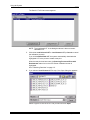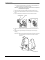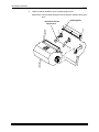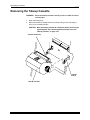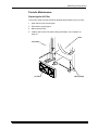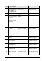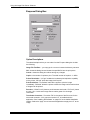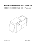
1
KODAK PROFESSIONAL LED II Printer 20R
Operator’s Guide
Part No. 6B6192
© Eastman Kodak Company, 2000
All rights reserved. Contents of this publication may not be reproduced in any form
without permission from Eastman Kodak Company.
Regulatory Information
Radio Frequency Interference
The United States (47 CFR Part 15 Subpart B, FCC Class A, EMC)
This equipment has been tested and found to comply with the limits for a Class A
digital device, pursuant to Part 15 of the FCC Rules. These limits are designed to
provide reasonable protection against harmful interference when the equipment is
operated in a commercial environment. This equipment generates, uses, and can
radiate radio frequency energy and, if not installed and used in accordance with
the instruction manual, may cause harmful interference to radio communications.
Operation of this equipment in a residential area is likely to cause harmful
interference in which case the user will be required to correct the interference at
his own expense.
IMPORTANT: Changes or modifications to the product that are not authorized by
Eastman Kodak Company could void the FCC Certification and
negate your authority to operate this product.
Canada (ICES-003 Issue 2 Rev1 Canada, Class A, EMC)
This Class A digital apparatus meets all requirements of the Canadian
Interference-Causing Equipment Regulations.
Cet appareil numerique de la classe A respecte toutes les exigences du
Reglement sur le materiel brouilleur du Canada.
European Union (EU, CE Marking, EMC)
This equipment has been type tested and found to comply with the requirements
for electromagnetic compatibility as established by European Communities
Council Directive 89/336/EEC and Low Voltage Directive (Product Safety)
73/23/EEC.
Japan (VCCI, Class 1 EMC)
The following is a translation of the above statement:
“This equipment is in the Class 1 category (information to be used in commercial
and/or industrial areas. Consequently, when used in a residential area or in an
adjacent area thereto, radio interference may be caused to radios and TV
receivers, etc. Read the instructions for correct handling”.
Safety Regulations
IMPORTANT: This equipment incorporates high-voltage components. Adequate safeguards and interlocks
have been designed into this equipment to reduce the risk of injury during normal operation.
As with any electrical equipment of this kind, adequate ventilation must be provided to
minimize exposure to heat, dust, ozone, and other emissions. The following labels will be
found on the product. The exclamation point symbol (A) indicates that the user should refer
to this guide for safety information. The hot symbol (B) indicates a hot surface area on the
printer that should not be touched. The electrical hazard/shock warning symbol (C)
identifies the possibility of electrical shock inside an area that should only be accessed by
Kodak CES personnel.
A
CAUTION:
B
C
Before connecting or disconnecting the SCSI cable or terminator, turn off the power
for the printer and the host computer. Also, if you replace the SCSI cable, remove the
Ferrite bead from the existing SCSI cable and install it on the new SCSI cable.
Environmental Regulations
IMPORTANT: Always adhere to your local ordinances and regulations for disposal of paper, chemicals,
filters, cleaning supplies, etc.
Warranty Information
The following warranty information pertains to equipment that is installed in the United States
only. For equipment installed in countries other than the United States, the terms and conditions
of the new equipment warranty will be provided by the Kodak company in the country in which
the sale is finalized, or by a Kodak-appointed distributor in those countries where Kodak does
not have direct sales representation.
Warranty Period
Kodak warrants new equipment to function properly for 90 days from the date of initial
installation. This warranty covers the purchaser of this equipment as well as anyone else who
owns it during the warranty period.
Warranty Repair Coverage
If this equipment does not function properly during the warranty period, a Kodak Customer
Equipment Services Field Engineer will repair the equipment without charge during Kodak’s
normal working hours (usually 8:00 a.m. to 5:00 p.m., Monday through Friday). Such repair
service will include any adjustments and/or replacement of parts required to maintain your
equipment in good working order. Supply items are billed as required.
Off-hours services are available at overtime rates.
How to Obtain Service
For technical support, service, repair and fuse replacement information, contact Eastman Kodak
Company’s Technical Assistance Center at 1-800-822-1414.
Limitations
Warranty Service is limited to areas within Kodak’s established marketing centers in the
contiguous United States, the island of Oahu in Hawaii, and certain areas of Alaska.
This warranty does not cover circumstances beyond Kodak’s control; service or parts for any
attachments, accessories, or alterations not marketed by Kodak, nor to correct problems
resulting from their use.
Damaged caused by failure to meet electrical specifications in this manual will not be covered
under the warranty or service agreement claim.
Damage to the imaging shoe as a result of customer misuse or abuse will not be covered under
the warranty or service agreement claim. Do not use sharp objects to clear paper in this area.
Kodak makes no other warranties, express, implied or of merchantability, for this
equipment.
Repair or replacement without charge is Kodak’s only obligation under this warranty. Kodak will
not be responsible for any consequential or incidental damages resulting from the sale, use or
improper functioning of this equipment, even if loss or damage is caused by the negligence or
other fault of Kodak.
Such damages, for which Kodak will not be responsible, include, but are not limited to, loss of
revenue of profit, downtime costs, loss of use of the equipment, cost of any substitute
equipment, facilities or services or claims of your customers for such damages.
This limitation of liability will not apply to claims for injury to persons or damage to property
caused by the sole negligence or fault of Kodak or by persons under its direction or control.
Kodak Service Agreements
For information on Kodak Service Agreements, call Kodak Service Marketing Operations
at 1-800-645-6325.
Table Of Contents
About This Guide.....................................................................................................................................
Using This Guide....................................................................................................................
About Other Publications ......................................................................................................
Software Included With the Printer........................................................................................
Getting Help from Kodak........................................................................................................
xiii
xiii
xiv
xiv
xv
1 Introduction...........................................................................................................................................
Product Description...............................................................................................................
SCSI Interface ................................................................................................................
KODAK PROFESSIONAL LED II Printer 20R ................................................................
Installation and Service ..................................................................................................
Equipment Overview .............................................................................................................
1-1
1-1
1-1
1-1
1-1
1-2
2 Using the System ................................................................................................................................. 2-1
Starting up the Printer ........................................................................................................... 2-1
Calibrating the Printer ........................................................................................................... 2-2
Obtaining Densities ........................................................................................................ 2-5
Obtaining Densities from a File ................................................................................2-5
Using the Densitometer to Read Densities ..............................................................2-5
Completing the Calibration ............................................................................................. 2-6
Making Prints ........................................................................................................................ 2-8
Shutting Down the Printer ..................................................................................................... 2-8
Soft Shutdown ................................................................................................................ 2-8
Hard Shutdown ............................................................................................................... 2-9
3 Operating Procedures .......................................................................................................................... 3-1
Operator Control Panel (OCP) .............................................................................................. 3-2
OCP Key/Light Descriptions ........................................................................................... 3-3
Menu ........................................................................................................................3-4
Taking the Printer Offline .........................................................................................3-4
Cancelling Jobs ........................................................................................................3-4
Printing Deferred or Buffered Jobs ...........................................................................3-4
Status Messages ............................................................................................................ 3-5
Loading Paper Into the Supply Cassette............................................................................... 3-6
Removing the Supply Cassette ...................................................................................... 3-6
Loading the Paper .......................................................................................................... 3-7
Attaching a Digital Paper Saver.................................................................................... 3-10
Installing the Loaded Paper Supply Into the Printer ..................................................... 3-12
Installing the Takeup Cassette............................................................................................ 3-14
Preparing the Takeup Cassette .................................................................................... 3-14
Installing the Takeup Cassette ..................................................................................... 3-15
Cinching the Media to the Cardboard Core .................................................................. 3-17
Unloading the Paper from the Printer.................................................................................. 3-19
Reaching the End of Roll of Paper...................................................................................... 3-19
Removing the Takeup Cassette.......................................................................................... 3-20
Removing Exposed Paper from the Takeup Cassette.................................................. 3-21
Adjusting the Paper Hole Punchers ................................................................................... 3-22
September 2000
vii
Using the Printer Features .................................................................................................. 3-23
Accessing the Menu ..................................................................................................... 3-23
Unloading Paper ........................................................................................................... 3-23
Unloading the Supply and Takeup .........................................................................3-23
Unloading the Takeup and Rethread .....................................................................3-23
Shutdown and Restart .................................................................................................. 3-24
Shutdown ...............................................................................................................3-24
Restart ....................................................................................................................3-24
Selecting a Loading Option .......................................................................................... 3-24
Paper Loading Options ..........................................................................................3-25
Selecting the Paper Load Option ...........................................................................3-25
Changing the Paper Loading Option ......................................................................3-26
Additional Paper Loss ............................................................................................3-26
Changing the Length of Paper Remaining on the Supply Roll ..................................... 3-26
Setting the Length of the Paper Trailer......................................................................... 3-27
Setting the Punches ..................................................................................................... 3-27
Determining the Location of the Cut and Order Punches ......................................3-28
Using the Automatic Roll ID.......................................................................................... 3-29
Using Page Starts......................................................................................................... 3-29
Setting the Page Starts Value ................................................................................3-30
Producing Borderless Prints ...................................................................................3-30
Resetting the Defaults .................................................................................................. 3-31
Resetting the Parameters ......................................................................................3-31
Resetting the Printing LUTs ...................................................................................3-31
Resetting the Copyright Detection LUTs ................................................................3-32
Selecting the SCSI Ports .............................................................................................. 3-32
Setting the Target Pad Reads ...................................................................................... 3-32
Selecting A Modem ...................................................................................................... 3-33
Resetting the Modem Port .....................................................................................3-33
Checking the Modem Presence .............................................................................3-33
Setting the Time and Date ............................................................................................ 3-33
Setting the Current Time ........................................................................................3-33
Setting the Current Date ........................................................................................3-33
Setting the Current Day ..........................................................................................3-34
Setting the Amount of Space Between Images ............................................................ 3-34
Changing the Units of Measurement for Paper Sizes................................................... 3-35
Changing the Gutter Width ........................................................................................... 3-35
Accessing the Software Version Number ..................................................................... 3-35
Setting the Copyright Detection Feature ...................................................................... 3-36
Handling and Storing the Paper .......................................................................................... 3-37
Storing Paper by Using the Soft Shutdown Feature ..................................................... 3-37
About Printing...................................................................................................................... 3-37
Image Size.................................................................................................................... 3-37
Buffered and Unbuffered Jobs (or Deferred and Immediate) ....................................... 3-37
Host Software Functions Supported By the Printer ...................................................... 3-38
Bar Coding .............................................................................................................3-38
Pixel Doubling ........................................................................................................3-38
viii
September 2000
4 Maintaining the Equipment ................................................................................................................... 4-1
Maintaining the Printer .......................................................................................................... 4-1
Daily Maintenance .......................................................................................................... 4-1
Calibrating the Printer ..............................................................................................4-1
Removing the Punch Chad ......................................................................................4-2
Periodic Maintenance ..................................................................................................... 4-3
Replacing the Air Filter .............................................................................................4-3
5 Diagnostics and Troubleshooting ......................................................................................................... 5-1
Printer Error Messages ......................................................................................................... 5-1
Manual or Automatic Reinitialization............................................................................... 5-1
Printer Paper Path .......................................................................................................... 5-2
Printer Error Messages................................................................................................... 5-3
Miscellaneous Printer Error Messages ........................................................................... 5-8
Clearing Paper Jams ...................................................................................................... 5-9
Troubleshooting Observable Errors.............................................................................. 5-11
Additional Troubleshooting Tips for the Printer............................................................. 5-13
Calibration Troubleshooting ................................................................................................ 5-14
Calibration Graph ......................................................................................................... 5-14
Numbered Error Messages .......................................................................................... 5-14
Non-Numeric Error Messages ...................................................................................... 5-21
Getting Additional Help ....................................................................................................... 5-22
Appendix A: Ordering Supplies ..............................................................................................................
Accessories..........................................................................................................................
Supplies ...............................................................................................................................
Standard (U.S.) Paper..........................................................................................................
Metric Paper.........................................................................................................................
Leaders and Splice Tape .....................................................................................................
Publications..........................................................................................................................
A-1
A-1
A-1
A-2
A-2
A-3
A-3
Appendix B: Specifications .....................................................................................................................
Printer Specifications ...........................................................................................................
Dimensions and Weight.................................................................................................
Acoustic Specifications ..................................................................................................
Site Requirements................................................................................................................
Operator and Service Access ........................................................................................
Floor Requirements .......................................................................................................
Electrical ........................................................................................................................
Power Cords ..................................................................................................................
Power Outlets ................................................................................................................
Line Frequency ..............................................................................................................
Line Voltage...................................................................................................................
Power Receptacles (U.S. and Canada).........................................................................
Printer Power Receptacles (Europe) .............................................................................
Telephone line ...............................................................................................................
Densitometer .................................................................................................................
SCSI Cable ....................................................................................................................
Operating Environment..................................................................................................
B-1
B-1
B-1
B-1
B-2
B-2
B-2
B-3
B-3
B-4
B-4
B-5
B-6
B-7
B-8
B-8
B-8
B-8
September 2000
ix
Appendix C: Additional Calibration Information ...................................................................................... C-1
Installing the Calibration Software........................................................................................ C-1
System Requirements ................................................................................................... C-1
Installation Procedure .................................................................................................... C-2
Kodak Device Calibration Software...................................................................................... C-4
Application Window Definitions ..................................................................................... C-4
Starting the Kodak Device Calibration Software............................................................ C-6
Adding a Device ............................................................................................................ C-6
Editing the Log Settings................................................................................................. C-8
Updating a Device ......................................................................................................... C-9
Deleting a Device ........................................................................................................ C-10
Advanced Features of the LED II Calibration Software...................................................... C-11
Viewing Graphs ........................................................................................................... C-11
Sending LUTs .............................................................................................................. C-16
Sending Targets .......................................................................................................... C-17
Editing the Calibration Configuration ........................................................................... C-20
Editing Information on the Procedure Tab ............................................................ C-22
Editing Information on the Density Source Tab ..................................................... C-24
Editing Information on the Aim Tab ....................................................................... C-25
Editing Information on the History Tab .................................................................. C-26
Editing Information on the Paper Tab .................................................................... C-27
Editing Information on the DP2 (Windows NT) or KPIS (Macintosh) Tab ............. C-27
Completing the Edit Configuration ........................................................................ C-31
Creating a Density File for Use with Calibration .......................................................... C-32
File Formats................................................................................................................. C-32
Installing the Densitometer................................................................................................. C-33
Appendix D: Using the Image Print Server Software.............................................................................. D-1
Installing the IPS Software ................................................................................................... D-1
Hardware Requirements................................................................................................ D-1
Software Requirements ................................................................................................. D-1
Installing the Software ................................................................................................... D-2
Using the Image Print Server ............................................................................................... D-2
Inserting Images into the Print Queue ........................................................................... D-2
Source Directory Insertion ....................................................................................... D-2
Menu Bar Insertion .................................................................................................. D-2
Suspending and Resuming ........................................................................................... D-3
Failed Jobs .................................................................................................................... D-3
Attended Operation ....................................................................................................... D-3
Enqueue Example ......................................................................................................... D-4
Dialog Boxes and Print Options ........................................................................................... D-6
Option Descriptions ....................................................................................................... D-7
Enqueue Dialog Box ...................................................................................................... D-8
Option Descriptions ................................................................................................. D-8
Source Directory Preferences Dialog Box ..................................................................... D-9
Option Descriptions ................................................................................................. D-9
Initialize Default Parameters Dialog Box ..................................................................... D-10
Description ............................................................................................................ D-10
File Format Details ...................................................................................................... D-10
Supported Tags ........................................................................................................... D-10
LZW Compression ....................................................................................................... D-10
x
September 2000
Appendix E: Using the PHOTOSHOP Export Module ............................................................................ E-1
Installing the Export Module ................................................................................................. E-1
Hardware Requirements................................................................................................ E-1
Software Requirements ................................................................................................. E-1
Installing the Software ................................................................................................... E-2
Printing Images .................................................................................................................... E-3
Dialog Boxes and Print Options ........................................................................................... E-6
KODAK LED Main Dialog Box ....................................................................................... E-6
Option Descriptions ................................................................................................. E-6
Other options ........................................................................................................... E-7
Punch Attributes ............................................................................................................ E-7
Option Descriptions ................................................................................................. E-7
Page Layout Attributes ................................................................................................. E-8
Option Descriptions ................................................................................................. E-8
Select an LED Printer Dialog Box.................................................................................. E-8
Option Descriptions ....................................................................................................... E-9
Printer Status Dialog Box .............................................................................................. E-9
Option Descriptions ..................................................................................................... E-10
Troubleshooting ................................................................................................................. E-10
Error messages ........................................................................................................... E-10
General error messages ....................................................................................... E-10
Other Problems ..................................................................................................... E-11
Index.................................................................................................................................................. Index-1
September 2000
xi
About This Guide
This is a User’s Guide for the KODAK PROFESSIONAL LED II Printer 20R. It
provides step-by-step instructions for the operations you perform while using the
Printer. It also includes procedures and information for operating, maintaining,
troubleshooting, and calibrating the printer.
Also included in this guide are instructions for installing and using the various
software packages needed.
This guide is intended for personnel who operate this system. It assumes that you
can perform basic computer operations.WINDOWS NT and MACINTOSH
Platforms are supported in this guide.
Using This Guide
This guide is organized as follows:
September 2000
Chapter 1
Introduction—describes and illustrates the KODAK
PROFESSIONAL LED II Printer 20R. This chapter includes
general and introductory information for all of the equipment.
Chapter 2
Using the System—explains how to use the printer. It
includes the step-by-step instructions for daily operation,
from startup to shutdown.
Chapter 3
System Operating Procedures—provides an overview of
the OCP and all of the procedures for operating the Printer.
Chapter 4
Maintaining the Equipment—includes the information that
you need to properly maintain the printer. All maintenance
procedures are categorized by frequency.
Chapter 5
Diagnostics and Troubleshooting—provides an error
code listing, solutions to common operational problems for
the printer and calibration. It also provides information for
obtaining additional help.
Appendix A
Ordering Equipment, Accessories, and Supplies—
provides ordering information for many associated items. It
includes information such as size, quantities, and catalog
numbers.
Appendix B
Specifications—provides specifications, site
requirements, and environmental information for the system.
Appendix C
Calibrating the Printer—describes the calibration
functions for the KODAK Calibration Software as well as
Printer Calibration Software.
Appendices D-F
Software—explains how to install and use the software that
is included with the printer.
xiii
About This Guide
About Other Publications
The following publication is included with the printer:
Quick Reference Guide for the KODAK PROFESSIONAL LED II Printer 20R
and the KODAK PROFESSIONAL LED II Processor 20R–provides quick and
easily accessible information for operating and maintaining the printer as well as
answers to common printer problems and hints for operating the processor. Keep
the Quick Reference Guide close to your printer.
Software Included With the Printer
The compact disc (CD) included with the KODAK PROFESSIONAL LED II Printer
20R contains the KODAK Calibration Software and the Printer Calibration
Software for WINDOWS NT and MACINTOSH Host Computers. It also includes
additional applications the printer can interface with.
This software is usually installed by a Kodak representative. However, installation
instructions are included in this Operator’s Guide.
A PDF file of this Operator’s Guide is also included on the CD.
You can find the latest software and documentation for the KODAK
PROFESSIONAL LED II Printers on the Kodak Web site: www.kodak.com.
xiv
September 2000
About This Guide
Getting Help from Kodak
Your Kodak sales representative is the best source for information about setting
up and operating your printer and for obtaining accessories and supplies. Please
contact your Kodak sales representative if you have any questions.
Kodak Sales Representative:___________________________
Representative’s Telephone Number:_____________________
K-Number:_________________________________________
In addition, for technical support in the U.S., call 1-800-3Kodak3 between
8:00 a.m. and 11:00 p.m. Eastern Standard Time on regular business days.
Telephone numbers for help outside the United States are in the Chapter 5,
Diagnostics and Troubleshooting.
You can also use the technical support number for information on:
•
•
•
•
•
operating the printer
how or where to obtain supplies
how to obtain service
the warranty
other Kodak products
If you are calling for technical support, please know your printer’s K-Number. The
K-Number label is attached to the front of the printer, next to the operator
control panel.
Product Literature
The faxback number for product literature is 1-800-508-1531. You may call this
number 7 days a week, 24 hours a day.
September 2000
xv
1 Introduction
This chapter includes the following information about the KODAK
PROFESSIONAL LED II Printer 20R:
Product Description ...........................................................................................1-1
SCSI Interface .............................................................................................1-1
KODAK PROFESSIONAL LED II Printer 20R ............................................1-1
Installation and Service ...............................................................................1-2
Equipment Overview ..........................................................................................1-2
Product Description
The KODAK PROFESSIONAL LED II 20R printing system offers a combination of
printing options that produces photographic quality output of digital images. The
images are printed at a resolution of 250 dpi and at sizes varying from 8 x 10 in. to
20 x 33 in.
Images printed with this system are comparable to images produced on an optical
printer. By using KODAK PROFESSIONAL Digital Paper with proper color
management, the 20R printer provides the “look” of VPS film on KODAK PORTRA
or SUPRA Paper, or GOLD Film on KODAK EKTACOLOR Edge Paper.
The system consists of a MACINTOSH or PC host computer to manage and
manipulate the digital source image, a SCSI interface to transfer the digital image
to the printing system, and the KODAK PROFESSIONAL LED II Printer 20R to
expose the digital image.
You can use a variety of software applications (such as KODAK Image Print
Server Software) to manage and manipulate the digital images.
SCSI Interface
A SCSI cable connects the host computer to the KODAK PROFESSIONAL LED II
Printer 20R. This interface transfers the digital image data from the host computer
to the printer.
KODAK PROFESSIONAL LED II Printer 20R
The KODAK PROFESSIONAL LED II Printer 20R exposes digital images on
photographic quality paper using a sophisticated technology involving Light
Emitting Diodes (LEDs). The printer uses KODAK PROFESSIONAL Digital Paper,
in 10, 11, 12, 20 inch and A4 widths to create prints of 6.5 x 10 in. to 20 x 33 in.
The images are wound onto a takeup roll which is then taken to an RA-4
processor for developing.
Installation and Service
The KODAK PROFESSIONAL LED II Printer 20R printer must be installed and
serviced by a qualified Kodak service representative.
September 2000
1-1
Introduction
Equipment Overview
paper supply
door
Front View
printer
paper takeup
door
host computer and SCSI cable
(not included)
front
slack loop
door
operator
control panel
densitometer (not included)
front door
Rear View
connector
ports
circuit
breaker
back door
back slack loop door
power cord
1-2
September 2000
2 Using the System
This chapter explains how to use the KODAK PROFESSIONAL LED II Printer
20R. It takes you from startup to shutdown. Topics include:
Starting up the Printer ........................................................................................2-1
Calibrating the Printer ........................................................................................2-2
Obtaining Densities .....................................................................................2-4
Completing the Calibration ..........................................................................2-6
Making Prints .....................................................................................................2-7
Shutting Down the Printer ..................................................................................2-8
Soft Shutdown ..............................................................................................2-8
Hard Shutdown ...........................................................................................2-9
Starting up the Printer
1. If needed, turn the circuit breaker on the back of the printer on.
2. Press the Start key on the OCP to begin the printer initialization process.
If paper is loaded, when initialization is complete (3 to 4 minutes) the
message “Status: ON LINE - Ready” appears on the OCP. Startup is complete
and the printer is ready to print. Turn the host computer on; then go to the next
page and calibrate the printer.
If paper is not loaded, the message “Out of paper, open supply door
to load” appears on the OCP. Do the procedures below.
• “Loading Paper Into the Supply Cassette” on page 3-6
• “Installing the Takeup Cassette” on page 3-14
When “On-line and Ready” is displayed, turn the host computer on. Go to
the next page and calibrate the printer.
September 2000
2-1
Using the System
Calibrating the Printer
You need to calibrate the printer when you start the system up each day. You also
need to calibrate the printer when:
• you change paper
• print quality is questionable
• the temperature at the site changes more than 5° F (2.8° C)
• if running more than one shift, at the beginning of each shift
If you are calibrating at any time other than during the daily startup procedure:
Before you begin, make sure the printer is not receiving printing commands from
the host.
NOTE: Most windows displayed in this section are from the Windows NT version
of the software. The windows for the Macintosh version of the software are
similar.
For information about editing the calibration settings (for example, you may want
to display a calibration graph only if calibration is out of tolerance), see “Editing
the Calibration Configuration” on page C-20.
To calibrate the printer:
1. Check that:
• the densitometer is connected and calibrated
• the printer status is “Online and Ready”
• the processor is in control
• the calibration application is running
2. Select the icon for the LED Printer on the KODAK Device Calibration screen
and click the Calibrate icon. The calibration software needs complete control
of the printer to successfully calibrate the printer.
IMPORTANT: If no icon appears on the KODAK Device Calibration screen, you
need to add a calibration device. See “Adding a Device” on
page C-6.
Calibrate
icon
2-2
September 2000
Using the System
The LED Calibration screen appears.
3. Click Go to start the calibration cycle.
Go icon
This icon highlights after
you select Go
Downloading LUTs and Sending Test Print highlights.
If the configuration file specifies to Ask if processor is in control, the
Process In Control dialog box appears.
The processor is critical to printer calibration. You can calibrate the printer
only if the processor is in control. Densitometers require calibration at regular
intervals. Refer to your densitometer’s manual for instructions on how to
calibrate your densitometer.
4. Click Yes.
September 2000
2-3
Using the System
The Send LUT to Printer screen appears.
NOTE: The highlighted LUT in the dialog box above is the most recent
calibration LUT.
5. Click either Load Selected LUT or Load Custom LUT (or Cancel to cancel
the calibration process).
If you click Load Selected LUT, the system automatically downloads the
highlighted LUT to the printer to create a test print.
When the test print has been sent, the Scanning Processed Print with
Densitometer status icon on the LED Printer Calibration screen is
highlighted.
Go to “Obtaining Densities” on page 2-5.
6. If you selected Load Custom LUT in step 5, the Open dialog box appears.
Select or type the name of the LUT file you want and click Open.
2-4
September 2000
Using the System
The system automatically downloads the LUT file to the printer to create a test
print. When the test print has been sent to the printer, the Scanning
Processed Print with Densitometer status icon on the KODAK LED Printer
Calibration screen is highlighted.
Obtaining Densities
Obtaining Densities from a File
If the configuration settings include obtaining the density data from a file, the
Waiting for Density File dialog box appears. Otherwise, go to “Using the
Densitometer to Read Densities.”
NOTE: To create a density file, see “Creating a Density File for Use with Calibration”
on page C-32.
1. Click OK to continue with the calibration process.
2. Go to “Completing the Calibration” on page 2-6.
Using the Densitometer to Read Densities
Do the following to scan the neutral (gray) patches on the processed test print into
the densitometer (refer to your densitometer manual for detailed instructions on
using the densitometer):
1. Slide the lever on the densitometer to position 15. Align the edge of the test
print with the lever on the densitometer. Gently feed the test print through the
densitometer to scan the patches labeled “even”.
2. Slide the lever on the densitometer to position 20. Align the edge of the test
print with the lever on the densitometer. Gently feed the test print through the
densitometer to scan the patches labeled “odd”.
September 2000
2-5
Using the System
3. Slide the lever on the densitometer to position 30. Align the edge of the test
print with the lever on the densitometer. Gently feed the test print through the
densitometer to scan the patches labeled “both”.
Lever
Test print
If the test print is read successfully, several messages will appear in the status
bar; the final message indicates that the densitometer values have been
successfully received. Go to “Completing the Calibration.”
If the test print is not read successfully, refer to “Calibration Troubleshooting”
on page 5-14.
Completing the Calibration
1. If calibration is in tolerance, the LUT Attributes dialog box appears.
a. Enter a name or comment in the dialog box. The comment you enter will
appear on the Send LUT to Printer screen to identify the LUT file with a
name that is meaningful to you (up to 75 characters).
b. Click OK.
The new printing LUT is calculated and downloaded. “Calibration
Complete” appears in the status bar. The calibration is complete.
2-6
September 2000
Using the System
2. If calibration is out of tolerance, it may be necessary to run four or more
iterations of the calibration cycle to achieve a successful calibration.
If the print densities are out of tolerance, a graph appears, allowing you to
select the type of data and planes that you want to see displayed.
a. Click OK.
The following list of options appears.
Re-read the densitometer values is the most useful when the graphs
show an unusual plot. Rereading the test print lets you validate the graph,
then returns you to the Out of Tolerance dialog box.
Iterate again using a newly calculated calibration LUT allows you to
keep printing test prints with the newly created LUT without having to save
the LUT table.
Calculate and download a printing LUT and stop: When you select this
option, the file is saved and given the same creation date and time as the
name.
Cancel and return the printer to its original state saves nothing. Any
corrupted data created after you saved the last time is thrown away.
September 2000
2-7
Using the System
b. Select one of the four options to try to complete the calibration
successfully.
• If the Out of Tolerance dialog box appears again, repeat this step until
you get a successful calibration; go to step 1.
• If you cannot get a successful calibration, request help from a system
administrator or service person.
Making Prints
You can make prints using the LED Printer 20R with a wide variety of applications
that run on WINDOWS NT Computers and MACINTOSH Computers. One
application that is widely used for printing is the KODAK PROFESSIONAL
Imaging System.
Two applications that you may wish to print from are included with the system.
You can use the KODAK PROFESSIONAL Image Print Server for WINDOWS NT
to print TIFF images. You can use the Export Module for ADOBE PHOTOSHOP
that runs on MACINTOSH Computers to print images from the PHOTOSHOP
application.
For more information about these applications, see the appropriate Appendix in
this guide.
Shutting Down the Printer
There are two methods for shutting down the printer. The soft shutdown method is
the recommended way to shut down the printer overnight or for a period of several
hours. The hard shutdown method should be used for shutting down the printer
for an extended period of time (several days or longer).
Soft Shutdown
IMPORTANT: The soft shutdown method ensures that all printer information is
saved and that the print head is safely turned off if paper is loaded
in the printer.
1. Check that all jobs in the print queue are printed.
2. Press the On/Off Line key on the OCP to take the printer offline.
3. Press the Menu button on the OCP to access the menu.
4. Select “Shutdown” in the message display.
5. Press the Start key.
6. Select “Shutdown now” in the message display.
7. Press the Select key to begin the shutdown.
NOTE: If any jobs are not complete, you will be asked if you want to delete the
remaining jobs before you can select Shutdown.
2-8
September 2000
Using the System
Hard Shutdown
Use this method for shutting down the printer for an extended period of time
(several days or longer).
1. Do a soft shutdown. See “Soft Shutdown” on page 2-8.
CAUTION: Turn off the circuit breaker only after doing the soft shutdown.
Otherwise, you could lose printer status information and will
cause dark lines to appear in the middle of the prints if paper
is loaded.
2. Turn off the circuit breaker on the back of the printer.
circuit breaker
September 2000
2-9
3 Operating Procedures
This section provides the information you need to operate the KODAK
PROFESSIONAL LED II Printer 20R. Topics include:
Operator Control Panel (OCP) ...........................................................................3-2
OCP Key/Light Descriptions ........................................................................3-3
Status Messages .........................................................................................3-5
Loading Paper Into the Supply Cassette ...........................................................3-6
Removing the Supply Cassette ....................................................................3-6
Loading the Paper .......................................................................................3-7
Attaching a Digital Paper Saver ................................................................3-10
Installing the Loaded Paper Supply Into the Printer ..................................3-12
Installing the Takeup Cassette ........................................................................3-14
Preparing the Takeup Cassette ................................................................3-14
Installing the Takeup Cassette ..................................................................3-15
Cinching the Media to the Cardboard Core ...............................................3-17
Unloading the Paper from the Printer ..............................................................3-19
Reaching the End of Roll of Paper ..................................................................3-19
Removing the Takeup Cassette ......................................................................3-20
Removing Exposed Paper From the Takeup Cassette .............................3-21
Adjusting the Paper Hole Punchers ................................................................3-22
Using the Printer Features ...............................................................................3-23
Accessing the Menu ..................................................................................3-23
Unloading Paper .......................................................................................3-23
Shutdown and Restart ...............................................................................3-24
Selecting a Loading Option .......................................................................3-24
Changing the Length of Paper Remaining on the Supply Roll ..................3-26
Setting the Length of the Paper Trailer .....................................................3-27
Setting the Punches ..................................................................................3-27
Using the Automatic Roll ID ......................................................................3-29
Using Page Starts .....................................................................................3-29
Resetting the Defaults ...............................................................................3-31
Selecting the SCSI Ports ...........................................................................3-32
Setting the Target Pad Reads ...................................................................3-32
Selecting A Modem ...................................................................................3-33
Setting the Time and Date ........................................................................3-33
Setting the Amount of Space Between Images .........................................3-34
Changing the Units of Measurement for Paper Sizes ...............................3-35
Changing the Gutter Width ........................................................................3-35
Accessing the Software Version Number ..................................................3-35
Setting the Copyright Detection Feature ...................................................3-36
Handling and Storing the Paper .......................................................................3-37
Storing Paper by Using the Soft Shutdown Feature .................................3-37
About Printing ..................................................................................................3-37
Image Size ................................................................................................3-37
Buffered and Unbuffered Jobs (or Deferred and Immediate) ....................3-37
Host Software Functions Supported By the Printer ...................................3-38
September 2000
3-1
Operating Procedures
Operator Control Panel (OCP)
The operator control panel (OCP) for the printer allows you to view and control:
•
•
•
•
•
•
•
current status of the printer
current time of day
paper specifications
error and power status
cancel, on/off line and menu functions
parameters of the printer
error messages
current status
LED indicator
lights
time of day
LCD display
Status: Initializing
Status:
Initializing
Pages
Waiting:
Paper Width:
Paper
Supply:
Paper
Length:
2:43
Power
Error
Standby
Paper Paper
Width:
Width: 100
Paper Paper
Takeup:
Length: 0
Start
Cancel
On/Off Line
Menu
Select
printing information
function keys
Select
key
Up, Down, and Right
select keys
The display on the OCP is a 4 line by 40 character liquid crystal display (LCD). An
audible beeper is installed to the right of the LCD display. Each of the function
keys also operates as the arrow key (selector) directly below it when Menu has
been pressed. LED indicator lights illuminate to indicate power, error, and standby
statuses.
The operator control panel (OCP) displays the current status of the printer,
including the following information:
3-2
•
Pages Waiting – the number of printing jobs that are waiting in the print
queue/buffer
•
Paper Supply – the approximate amount of paper left in the paper cassette.
This information is input by you and is for your convenience only
•
Paper Width – the width of the current roll of paper that is installed in the
printer
•
Paper Takeup – the amount of paper that has been fed into the takeup
(“**” will appear in this field if the paper is not cinched in the takeup cassette)
September 2000
Operating Procedures
OCP Key/Light Descriptions
Key/Light
Key /LED
Indicator Light
Description/Function
Start
Start Key
The Start key turns on the power for the printer when the printer has
been shut down through the OCP. When using the OCP menu, the
Start key functions as a Select key to select the highlighted item
from the OCP menu.
Cancel
Cancel Key
Pressing Cancel causes the job that is currently printing to quit. In
addition, the printer automatically goes into the Offline mode after
the current printing job has quit.
On/Off Line Key
This key toggles between the Online and Offline modes. If you press
this key when the printer is in the Online mode, the printer goes into
the Offline mode. If you press this key when the printer is in the
Offline mode, the printer goes into the Online mode.
Menu Key
Pressing this key activates the menu for the OCP when the printer
is in the Offline mode.
Arrow Keys
When using the OCP menu, the Cancel key functions as a Right
Arrow, the On/Off Line key functions as an Up Arrow, and the
Menu key functions as a Down Arrow.
Select Key
When using the OCP menu, the Start key functions as a Select key
to select the highlighted item from the OCP menu.
Power
Power Light
The power light illuminates to indicate that the main power for the
printer is on.
Error
Error Light
The error light illuminates to indicate that a printer error occurred.
Standby Light
The standby light illuminates to indicate that the printer has been
shut down from the OCP and is now in the Standby mode, waiting
for Start to be pressed.
On/Off Line
Menu
Select
Standby
September 2000
3-3
Operating Procedures
Menu
The menu allows you to access other printer features.
NOTE: To access the menu, the print queue must not have any pages waiting to
be printed.
1. Press On/Off Line to take the printer offline.
2. Press Menu.
Taking the Printer Offline
This feature is useful when you need to access the printer OCP menu.
When the printer is offline, it cannot send jobs to the processor or accept jobs
from the host.
To take the printer offline, press On/Off Line on the OCP. If a job is printing when
you take the printer offline, the job will complete printing.
Online Mode
The Online mode is the normal mode and must be activated for the printer to
accept print jobs from the host computer.
Offline Mode
When the printer is in the Offline mode it cannot accept print jobs from the host
computer. When an error occurs, the printer is automatically placed into the
Offline mode.
Cancelling Jobs
To cancel the sheet currently being printed, press Cancel on the OCP. After the
sheet has been cancelled, the printer automatically toggles to the Offline mode.
To cancel all jobs waiting to be printed:
1. Press Cancel on the OCP to cancel the sheet that is currently printing.
2. Press Menu twice.
Printing Deferred or Buffered Jobs
“Pages Deferred” displays on the OCP and a number other than zero displays in
the Pages Waiting field when one or more jobs are waiting to be printed.
1. Press On/Off Line to take the printer offline.
2. Press Menu.
3. Press Start to print the jobs.
3-4
September 2000
Operating Procedures
Status Messages
Status messages display on the LCD display of the OCP to indicate the status or
current state of the printer.
Status Message/Printer State
September 2000
Definition
status: ON LINE – Ready
The printer is idle and ready to accept jobs.
status: ON LINE – Processing
The printer is currently downloading or processing a
job.
status: ON LINE – Pages Deferred
Pages are waiting and nothing is being
downloaded. If jobs were sent with the “Defer Print”
or “Buffer” option, the printer is waiting for more
data to fill the frame store.
status: ON LINE – Printing
The printer is printing and may also be processing
more jobs.
status: OFF LINE – Idle
The printer is currently offline. No jobs exist in the
printer. “Idle” is used instead of “Ready” because
the printer is actually idle (not doing anything) and
will not accept jobs.
status: OFF LINE – Processing
The printer is offline but a job is being downloaded.
A print cycle will not be initiated.
status: OFF LINE – Pages Deferred
The printer is offline but there are jobs in the printer
that are waiting to be printed. A print cycle will not
be initiated.
status: OFF LINE – Printing
The printer will complete the current print cycle and
then pause.
status: OFF LINE – Cancelling
Cancel was pressed when the printer was printing.
The sheet that was printing was immediately
terminated. This message is also displayed when
you select “Yes” to the prompt to cancel all
remaining jobs when you enter the menu.
status: Initializing
The printer is powering up (after Standby has been
pressed or the printer has been turned on).
status: ON LINE – Resetting
The print engine is being reset because of an error
or operator intervention. The printer will return to the
“ON LINE – Ready” state after the machine reset is
complete (even if the printer was offline because of
an error or key that was pressed before the reset).
status: Printer Error:
<Error Message>
A printer error (such as a paper jam) has occurred.
The error message is displayed on the second line
of the display. For a complete list of error
messages, see “Printer Error Messages” on
page 5-1.
3-5
Operating Procedures
Loading Paper Into the Supply Cassette
WARNING: Move the supply cassette from the printer to a table to load or
unload paper.
One 10- to 20-inch supply cassette and one 10- to 20-inch takeup cassette are
included with the printer and are designed to hold rolls of paper that are 10-, 11-,
12-, 20-inch, and A4 widths.
The supply cassette and takeup cassette are not interchangeable.
Removing the Supply Cassette
1. Open the paper supply door.
2. Unlock the cassette clamp for the supply cassette.
3. Remove the empty supply cassette.
supply cassette
cassette
clamp
paper supply
door
3-6
September 2000
Operating Procedures
Loading the Paper
1. Unlock the supply cassette locks.
2. Open the supply cassette.
3. If necessary, remove paper scraps from the core support assembly.
4. Remove the old core and support assembly from the supply cassette.
NOTE: Keep the felt surfaces clean to prevent scratches on the paper.
old core and core support assembly
felt
felt
supply cassette locks
5. Remove the screw lock and the old cardboard core from the core support
assembly.
6. Pull the metal spring for the screw adjuster away from the gear and slide the
screw adjuster to the correct position until it locks into place in the detent.
screw adjuster
cardboard core
gear
screw lock
core support
assembly
September 2000
3-7
Operating Procedures
TIP: Practice the following steps in the light with an empty cardboard core
before you load a new roll of paper in the dark.
CAUTION: Loading paper into the paper cassette must be completed in
a darkroom with the lights off.
7. Position the paper so that the lead edge of the paper is away from you.
8. Insert the core support assembly from the left side into the roll of paper as
shown.
9. Push the cardboard core toward the gear until it engages the detent.
cardboard core
detent
10. Install the screw lock onto the core support assembly and ensure that it is
snug.
11. Place the core support assembly with the full paper roll into the supply
cassette.
IMPORTANT: Make sure that the right and left edges of the paper on the paper
roll remain aligned. Do not allow the roll of paper to slide or
“telescope”.
screw lock
3-8
September 2000
Operating Procedures
12. Feed the lead edge of the paper through the slotted opening in the paper
cassette.
lead edge of the paper
slotted opening
image or emulsion
side
core support assembly
(side without the gear)
13. Close the supply cassette and latch the supply cassette locks.
NOTE: Be sure that the core support assembly rotates freely in the supply
cassette and that the paper feeds freely.
supply cassette lock
NOTES: – When the paper cassette is locked, you can turn on the room lights.
– See page 3-10 for instructions on how to install a digital printer
paper saver.
IMPORTANT: When moving the supply cassette, pick up and carry the cassette
by both handles to prevent the paper from sliding or “telescoping”
to one side.
September 2000
3-9
Operating Procedures
Attaching a Digital Paper Saver
To save paper that is lost during the paper loading process when using the
“1-Step Normal” paper loading option, you may install a digital printer paper saver
(leader) to the lead edge of the roll of paper. Using the digital printer paper saver
reduces the amount of paper lost from threading the printer by 5.5 feet as shown
in the table below.
Threading Method
Amount of Unprintable Paper*
Paper Leader
9 feet
Digital Printer Paper Saver
3.5 feet
*For additional paper saving, see “Selecting a Loading Option” on page 3-24.
To order digital printer paper savers and splice tape, see “Leaders and Splice
Tape” on page A-3.
NOTE: The digital printer paper saver may be used many times.
CAUTION: To prevent spots or scratches on images, keep the digital printer
paper saver away from surfaces that have dust and dirt on them.
1. Load the paper into the supply cassette. See “Loading Paper Into the Supply
Cassette” on page 3-6.
2. If necessary, cut a straight edge on the lead edge of the paper that is coming
through the slotted opening in the supply cassette.
3. Cut a piece of splice tape that is approximately 2 inches longer than the width
of the supply cassette.
4. Set the splice tape on the supply cassette with the adhesive side facing up.
5. Place the lead edge of the paper onto the splice tape.
6. Place the trail edge of the digital printer paper saver (the edge without the
hole) on the splice tape.
NOTE: If the digital printer paper saver is new, wipe it with a damp cloth to
remove dust and static electricity.
IMPORTANT: The digital printer paper saver must be the same width as the
paper. Also, the curl of the digital printer paper saver and the curl
of the paper must match.
lead edge
of the paper
3-10
splice tape
lead edge of the
digital printer
paper saver
September 2000
Operating Procedures
7. Fold the edges of the splice tape over the digital printer paper saver and the
paper.
8. Cut a second piece of splice tape that is slightly smaller than the width of the
paper.
9. Install the second piece of splice tape over the paper and the digital printer
paper saver.
second piece of
splice tape
10. Turn the core support assembly to rewind the paper and digital printer paper
saver into the supply cassette.
NOTE: Do not wind the entire digital printer paper saver into the supply
cassette.
September 2000
3-11
Operating Procedures
Installing the Loaded Paper Supply Into the Printer
1. Open the paper supply door.
2. Empty the punch chad tray. See “Removing the Punch Chad” on page 4-2.
3. Align the slot on the bottom of the supply cassette with the plate on the bottom
of the shelf and slide the supply cassette into place on the shelf.
shelf
Emulsion
(image) side of
paper (or paper saver)
plate
cassette clamp
slot
4. Check that the gear on the supply cassette aligns and meshes with the gear
on the printer.
5. Lock the clamp to secure the paper cassette into place.
6. If you are not using the digital printer paper saver, check that the cut on the
lead edge of the paper is straight.
NOTE: Use scissors to cut the paper. Knives and razor blades will shred the
paper.
7. Adjust the right punch to the correct paper width (10, 11, 12 or 20 inch
and A4). See “Adjusting the Paper Hole Punchers” on page 3-22.
8. Press Start on the OCP.
9. Enter the number of feet on the roll of paper when prompted and if necessary,
enter the roll ID. See “Using the Automatic Roll ID” on page 3-29.
3-12
September 2000
Operating Procedures
10. When the message “Feed paper into printer...” appears, pull the lead edge of
the paper (or digital printer paper saver) out of the paper cassette and place
the lead edge of the paper into the punch slots.
right hole puncher
lead edge of
the paper
(or paper saver)
paper alignment
guide
gear on the
cassette
gear on the
printer
cassette
clamp
11. Slide the lead edge of the paper under the feed roller and static brushes using
both hands. Keep the paper flat until you feel it being pulled into the printer.
Keep the left edge of the paper against the paper alignment guide.
NOTE: The sound from the printer will change when the printer is ready to
advance the paper.
CAUTION: If the paper does not load properly or a paper jam occurs,
press Cancel on the OCP. Remove any paper from the shoe
area and repeat steps 7 through 10. If you are not using a digital
printer paper saver, make sure the lead edge is cut square and
does not have any bends or dings. If necessary, install a new
digital printer paper saver.
12. Close the paper supply door. If a 1-step load option is selected, the paper
automatically advances to the takeup cassette. When this is complete, a
message on the OCP prompts you to load the paper into the takeup cassette.
If a 2-step load option is selected, the prompt to cinch paper appears after the
appropriate length of images has been printed. See “Installing the Takeup
Cassette” on page 3-14.
NOTE: For additional paper saving methods, see “Selecting a Loading Option”
on page 3-24.
September 2000
3-13
Operating Procedures
Installing the Takeup Cassette
Preparing the Takeup Cassette
1. Unlatch the takeup cassette locks and open the takeup cassette.
2. Remove the core support assembly.
3. Move the screw adjuster to the correct position for the paper size that you are
loading. Pull the metal spring for the screw adjuster away from the gear and
slide the screw adjuster to the correct position until it locks into place in the
detent.
4. Slide the correct size cardboard core onto the core support assembly. Push
the cardboard core toward the flange until it engages the detent.
5. Install the flanged nut (when using 10-, 11-, 12-inch and A4 paper) or the
screw lock (for 20-inch paper) onto the core support assembly. The core
support assembly uses left hand threads. The threaded parts are color coded
to prevent confusion.
NOTE: Make sure the screw lock or flanged nut is secure.
6. Place three rubber bands over the cardboard core.
IMPORTANT: The rubber bands must have the same thickness and must not
be twisted or wrinkled when installed.
rubber bands
core support
assembly
screw
lock
screw adjuster
gear
flanged nut
cardboard core
3-14
September 2000
Operating Procedures
7. Install the core support assembly into the takeup cassette. See the
instructions on the label on the top of the takeup cassette.
NOTE: Make sure that the core support assembly is installed correctly in the
cutouts of the takeup cassette.
core support assembly
cutout
takeup
cassette
locks
8. Close the takeup cassette and latch the takeup cassette locks.
NOTE: Be sure the core support assembly rotates freely in the takeup cassette.
Installing the Takeup Cassette
1. Open the takeup door.
If the takeup cassette is in the printer and has paper in it, remove it.
See “Removing the Takeup Cassette” on page 3-20 or “Removing Exposed
Paper from the Takeup Cassette” on page 3-21.
2. If necessary, move the adjustable cassette support arm to accommodate the
size of the cassette you will be using. To move the adjustable arm:
a. Unscrew the clamping knob.
b. Move the arm to the correct position.
c. Reinstall the clamping knob and tighten.
September 2000
3-15
Operating Procedures
3. Install the takeup cassette onto the cassette support arms.
IMPORTANT: Check that the bearings on the cassette are seated in the support
arms.
adjustable cassette
support arm
3-16
clamping knob
September 2000
Operating Procedures
Cinching the Media to the Cardboard Core
Do the following to cinch (attach) the media (paper or digital printer paper saver)
to the cardboard core:
Cinching the Digital Printer
Paper Saver to the
Cardboard Core
Cinching Paper to the
Cardboard Core
(a) Hold the lead edge of the paper against the
cardboard core and close to the flange.
NOTE: Align the right edge of the paper with the
flange, making sure that the paper is not
skewed.
correct (paper edge is not skewed)
(b) Make a 3 inch cut in the lead edge of the
o
paper at a 45 angle to form a small flap.
(c) Pull the rubber band that is in the middle of the
cardboard core through the cut in the paper
and push the flap under the rubber band.
cut
September 2000
rubber
band
(a) Hold the lead edge of the digital printer paper
saver against the cardboard core and close to
the flange.
NOTE: Align the right edge of the digital printer
paper saver with the flange, making sure
that the paper saver is not skewed.
incorrect (paper edge is skewed)
(b) Pull the rubber band that is in the middle of the
cardboard core into the slot on the lead edge
of the digital printer paper saver.
slot
rubber
band
3-17
Operating Procedures
Cinching Paper to the
Cardboard Core
(d) Turn the flange on the core support assembly
until you have wrapped enough paper around
the cardboard core to cinch it to the core.
(e) Check that the right edge of the paper is still
aligned with the flange and close to it.
(f) Close and lock both sides of the takeup
cassette.
NOTE: The closed takeup cassette should move
freely when you press down on the front
of it. If necessary, reposition the takeup
cassette to move freely.
correct
cassette moves
up and down
freely
cassette is in
correct position
3-18
Cinching the Digital Printer
Paper Saver to the
Cardboard Core
(c) Turn the flange on the core support assembly
until you have wrapped enough digital printer
paper saver around the cardboard core to
cinch it to the core.
(d) Check that the right edge of the paper is still
aligned with the flange and close to it.
(e) Close and lock both sides of the takeup
cassette.
NOTE: The closed takeup cassette should move
freely when you press down the front of it.
If necessary, reposition the takeup
cassette to move freely.
incorrect
cassette will
not move up
and down
cassette is not in
correct position and
needs to be reseated
in the support arms
September 2000
Operating Procedures
Unloading the Paper from the Printer
The menu provides two options for unloading paper before the end of the roll is
detected:
•
Unload Supply and Takeup—Automatically makes a cut between the
exposed paper and the unexposed paper. The printer then winds the exposed
paper and trailer into the takeup cassette and rewinds the unexposed paper
into the supply cassette.
NOTE: Approximately 27 inches of unexposed paper will not be rewound into
the supply cassette.
•
Unload Takeup and Rethread—Automatically makes a cut between the
exposed paper and the unexposed paper. The printer then winds the exposed
paper and trailer into the takeup cassette. Paper is then advanced as
appropriate for the loading option selected. See “Selecting a Loading Option”
on page 3-24.
NOTE: You can determine the amount of trailer. See “Setting the Length of the
Paper Trailer” on page 3-27.
To choose one of the above options, see “Unloading Paper” on page 3-23.
Reaching the End of Roll of Paper
When the end of the roll is detected, the remainder of the paper is wound into the
takeup cassette and the message “Out of Paper...” is displayed on the OCP. See
“Removing Exposed Paper from the Takeup Cassette” on page 3-21 and “Loading
Paper Into the Supply Cassette” on page 3-6.
If an error has occurred and/or a door has been opened or closed after the printer
reached the end of the roll, the message “Out of Paper...” may display even
though paper is still partially threaded. To completely wind the paper into the
takeup cassette, either reinitialize the printer or see “Unloading the Paper from the
Printer” above.
September 2000
3-19
Operating Procedures
Removing the Takeup Cassette
WARNING: Move the takeup cassette from the printer to a table to load or
unload paper.
1. Open the takeup door.
2. Remove the takeup cassette from the printer by lifting it off of the support
arms by the cassette handles.
CAUTION: Move the takeup cassette to a darkroom before removing the
exposed paper. See “Removing Exposed Paper from the
Takeup Cassette” on page 3-21.
cassette handle (2)
support
arm (2)
takeup cassette
3-20
September 2000
Operating Procedures
Removing Exposed Paper from the Takeup Cassette
1. Remove the takeup cassette from the printer. See “Unloading the Paper from
the Printer” on page 3-19.
CAUTION: The following steps must be completed in a darkroom.
2. Unlatch the locks on the takeup cassette.
lock (2)
3. Open the takeup cassette.
4. Tape the edge of the paper to the paper roll to prevent the paper from
unwinding.
5. Remove the roll of paper from the takeup cassette.
NOTE: Keep the roll in the horizontal position to prevent it from “telescoping”.
tape
September 2000
3-21
Operating Procedures
6. Remove:
• screw lock or flange
• exposed paper from the core support assembly
NOTE: After removing the screw lock, tap the screw lock end of the core to
loosen the paper roll and make it easier to remove from the core support
assembly.
CAUTION: Keep the exposed paper in a darkroom or a dark bag until you
process it.
screw lock
flange
Adjusting the Paper Hole Punchers
1. Lift the arm for the right paper hole puncher.
2. Move the right paper hole puncher to the correct location. The hole puncher
falls into a detent on the sliding bar when it is in the correct location.
NOTE: The punch positions for A4 and 12 inch paper are very close together
and can be easily mistaken for each other. Make sure you set the paper
hole puncher to the correct position for the paper you are using.
right hole puncher
3-22
September 2000
Operating Procedures
Using the Printer Features
The following features are available from the menu on the OCP.
Accessing the Menu
1. Press On/Off line to take the printer offline.
2. Press Menu.
NOTE: If there are jobs waiting to be printed, the following options are available:
• “Cancel” – exit
• “Start” – prints jobs in the print queue and then accesses the menu
• “Menu” – deletes jobs in the print queue and then accesses the
menu
Unloading Paper
Follow one of the following procedures to unload paper. For more information
about these procedures, see “Unloading the Paper from the Printer” on page 3-19.
Unloading the Supply and Takeup
1. Select “Unload Paper” from the main menu on the OCP.
2. Select “Unload Supply and Takeup” from the main menu on the OCP.
3. Select “Unload Supply and Takeup NOW?”
The printer enters its unload paper sequence. When the unload paper
sequence is complete, the OCP returns to the main menu.
4. Select “Exit” to return to the OCP display. You will be prompted to load
another roll of paper into the printer.
Unloading the Takeup and Rethread
1. Select “Unload Paper” from the main menu on the OCP.
2. Select “Unload Supply and Rethread” from the main menu on the OCP.
3. Select “Unload Supply and Rethread NOW?”
The printer enters its unload paper sequence and you will be prompted to
recinch the takeup cassette. When the unload paper sequence is complete,
the OCP returns to the main menu.
4. Select “Exit” to return to the OCP display.
September 2000
3-23
Operating Procedures
Shutdown and Restart
Shutdown
1. Select “Shutdown” from the main menu on the OCP.
2. Select “Shutdown NOW?”
This causes the printer to shut down operations and enter the standby mode.
Restart
1. Select “Restart” from the main menu on the OCP.
2. Select “Restart NOW?”
This causes the printer to immediately shut down operations and reboot.
NOTE: This shutdown is not a soft shutdown and does not save the parameter
settings that have been made since the previous startup. Also, using
this feature may cause a black line on the paper in the shoe.
Selecting a Loading Option
The optional paper loading feature, available on the OCP’s main menu, allows
you to choose a loading option depending on your needs. The option you choose
determines how much paper is used during the load and whether or not the first
images from the shoe have cut or order punches.
NOTE: Do not use this feature if you are using a digital printer paper saver.
The four load options are:
3-24
•
1-Step Normal (factory default)—The first image exposure will be made on
the paper that was stored before the paper punch when the takeup cassette
was loaded. All images have the appropriate cut and order punches.
•
1-Step Save—Since the paper in the shoe is still unexposed, it is used for the
first image exposure. However, since the paper is threaded through the printer
during loading, the images on the first exposure are not individually punched.
•
2-Step Dark—the room is completely dark while the paper is being cinched
onto the takeup cassette. When loading, the paper is only partially advanced
through the printer. You must then expose some images and when prompted,
cinch the paper to the takeup cassette in the dark. The first exposure may or
may not be punched, depending on whether you loaded a new roll of paper or
are rethreading an existing roll. This option provides the least amount of
waste.
•
2-Step Light—the room is light while the paper is being cinched onto the
takeup cassette. When loading, the paper is only partially advanced through
the printer. You must then expose some images and when prompted, cinch
the paper to the takeup cassette in the light. The first exposure may or may
not be punched, depending on whether you loaded a new roll of paper or are
rethreading an existing roll.
September 2000
Operating Procedures
Paper Loading Options
Lead Edge Paper
Waste
Paper Punches
1-Step Normal
(factory default)
108 inches
at all images
1-Step Save
62 inches
at all images after the
first exposure
2-Step Dark
(new load)
35 inches
at all images
2-Step Dark
(rethread)
18 inches
at all images after the
first exposure
2-Step Light
(new load)
47 inches
at all images
2-Step Light
(rethread)
47 inches
at all images after the
first exposure
Load Option
NOTE: For options in which the first exposure is not individually punched, the first
exposure will use 33 inches of paper. To minimize paper waste, the size of
the images for the first exposure should total 33 inches whenever possible.
Selecting the Paper Load Option
1. Select “Setup” from the main menu on the OCP.
2. Select “Printer”.
3. Select “Paper Load”.
4. Use the Up and Down Arrows to select the desired paper load option.
5. Press Select to select/set the new value.
6. Select “Exit” to return to the previous menu on the OCP.
2-Step Paper Loading
The 2-step paper loading process is used when you choose the “2-Step Dark” or
“2-Step Light” option for paper loading. This process minimizes paper waste by
printing on the paper before the paper is threaded to the takeup area and you
cinch it onto the takeup cassette.
The 2-step loading process is different than the 1-step loading process that is
used for loading paper under “1-Step Normal” or “1-Step Save” conditions. When
you choose “1-Step Light” or “1-Step Save”, the paper is threaded through the
shoe and cinched onto the takeup cassette before images are printed.
September 2000
3-25
Operating Procedures
Changing the Paper Loading Option
When using the Paper Loading Feature, you should select the paper load option
before you load paper into the printer. However, you can change the paper load
option at any time. If you change the loading option:
•
before selecting “Unload Takeup and Rethread” from the main menu on the
OCP, the paper will follow the rethreading procedure for the loading option
that you selected.
•
after the paper is loaded but before the first exposure is made, the paper
loading process will not be affected. If you are using the “2-Step Dark” option
and the paper is not cinched, you will still be prompted to “go dark” when it is
time to cinch the paper.
When you change the paper loading option from “1-Step Normal” or “1-Step Save”
or “2-Step Dark” or “2-Step Light”, the printer will print the first exposure on the
paper that is already positioned in the shoe. Similarly, when you change the paper
loading option from “1-Step Subdued”, “2-Step Dark” or “2-Step Light” to “1-Step
Light”, the first exposure will not be made on the paper in the shoe and all images
will be punched appropriately.
Additional Paper Loss
(For 1-Step Save and 2-Step Rethread Paper Loading Only)
Only one exposure is made on the paper that is in the shoe after loading. Some
paper may be wasted if the total size of the images on the first exposure does not
fully use the paper in the shoe (33 inches). If “Automatic Roll ID” is enabled, the
first image on the roll (for the Roll ID) is 6.5 inches long. This leaves 22.5 inches
available for additional images.
If the first image for the second exposure is less than 12.5 inches,12 inches of
paper between the first and second exposure may be wasted.
If the printer is reinitialized before the first exposure, additional paper is advanced
and all images are individually punched.
Changing the Length of Paper Remaining on the
Supply Roll
The value displayed is the length of paper that is left on the supply roll or in the
takeup cassette. This number should be edited when a new or partially used
paper roll is installed in the printer. You will normally receive a prompt to enter this
number when a new roll is being loaded into the printer. The value should only
need to be modified here if there is a need to change the number. The range for
paper is 0 to 999.
1. Select “Setup” from the main menu on the OCP.
2. Select “Paper”.
3. Select “Supply Length”.
4. Select “Takeup Length”.
5. Use the Up and Down Arrows to select a new length for the paper.
6. Press Select to select/set the new value.
7. Select “Exit” to return to the previous menu on the OCP.
3-26
September 2000
Operating Procedures
Setting the Length of the Paper Trailer
This value determines the amount of unexposed paper to be added to the trail
edge of the paper wound into the takeup cassette when you send an “Unload
Takeup and Rethread” command.
1. Select “Setup” from the main menu on the OCP.
2. Select “Printer”.
3. Select “Trailer”.
4. Use the Up and Down Arrows to select a new trailer length (from 0 to 3000
pixels).
5. Press Select to select/set the new value.
6. Select “Exit” to return to the previous menu on the OCP.
Setting the Punches
The printer has two paper punches, the back paper punch (closest to the back of
the printer) and the front paper punch (closest to the front of the printer). The front
paper punch can be adjusted to accommodate the width of the paper.
The printer is capable of three types of paper punches:
Cut Punch—occurs automatically between each print. This punch can be made
by either the back or front paper punch.
Order Punch—controlled by a command that is sent from the host computer. This
punch can be made by either the back or front paper punch.
September 2000
3-27
Operating Procedures
Gutter Punch—controlled by a command sent from the host computer. See
“Changing the Gutter Width” on page 3-35. This punch is on the same side as the
cut punch and is 0.25 to 1.0 in. inside of the image (depending on the value of the
gutter width).
Cut and Order Punches on Same Side of the Paper
outline of paper
outline of image
0.25 in.
cut punches white
order punch
0.25 in.
white
front of the printer
Cut and Order Punches on Opposite Sides of the Paper
cut punches
order punch
Gutter Punches With Cut and Order Punches on Opposite Sides of the Paper
gutter width 0.25 in.
cut punches
order punch
order punch
gutter punches
NOTE: All three types of paper punches are made at the trail edges of the print.
Determining the Location of the Cut and Order Punches
1. Select “Setup” from the main menu on the OCP.
2. Select “Printer”.
3. Select “Cut Punches” or “Order Punches”.
4. Select “<>Punch Position”.
5. Select “front” or “back”.
6. Select “<> Punch Enabled”.
3-28
September 2000
Operating Procedures
Using the Automatic Roll ID
The printer has the ability to automatically print a roll identification (roll ID) at the
beginning of each roll.
When this feature is enabled, the roll id will be printed every time paper is loaded
into the printer and every time the paper is rethreaded (for example: when
“Unload Takeup and Rethread” is selected).
The roll ID includes the date, time, and roll ID number. The date and time are the
date and time that the roll of paper was loaded. The roll ID is a three digit number.
This number will automatically increment each time a new roll is loaded. During
loading, this number will be displayed on the OCP. The operator can change the
number or accept the incremented number.
If the printer runs out of paper while printing a job, an asterisk (*) will be printed
after the roll ID on the following roll to indicate that the first print(s) on this roll of
paper belong with the print(s) of the last job that was printed on the previous roll of
paper.
1. Select “Setup” from the main menu on the OCP.
2. Select “Printer”.
3. Select “More”.
4. Select “Roll ID”.
5. Select “Printer ID”. The printer ID will be printed with each roll ID and will not
change.
6. Select “Roll ID Enabled” and toggle to:
• “Yes” if you want a roll ID to be printed at the beginning of each roll
or
• “No” to not print a roll ID.
Using Page Starts
The value for “Page Starts” indicates the number of pixels between the back wall
of the printer and the edge of the image. For example, when the printer begins to
print, it moves the print head to the back wall of the printer and then advances it
toward the front of the printer by the number of pixels specified in the “page starts”
parameter (value).
The “page starts” value is set so that the edge of the image closest to the back of
the printer will print off of the paper and will then be borderless on the back edge
of the print.
NOTE: If the image size is wider than the paper, the front edge of the image will
also be borderless.
September 2000
3-29
Operating Procedures
Setting the Page Starts Value
1. Select “Setup” from the main menu on the OCP.
2. Select “Printer”.
3. Select “Page Starts”.
4. Select the Page Start you want to modify.
5. Use the Up and Down Arrows to select a new Page Start value.
6. Press Select to select the new value.
7. Select “Exit” to return to the previous menu on the OCP.
Producing Borderless Prints
To achieve borderless prints on both the front and back edges of the paper, you
must set the Page Starts value to adjust the location of the image so that both
edges of the image will print off of the paper.
NOTE: The image width must be at least 76 pixels wider than the width of the paper
to ensure a borderless print. For example:
Paper Size
Image Width in Pixels
10 inch
2576
11 inch
2826
12 inch
3076
20 inch
5076
A4
3000
outline of the paper
outline of the image
page start
back edge
front edge
If white borders are present on either the front or back edge of the print:
1. Measure the white border at both the lead (distance A) and the trail edge
(distance B) and determine its average width.
2. Convert the average width of the white border to a pixel value.
3-30
September 2000
Operating Procedures
3. Adjust the page starts value to the calculated pixel value. If the white border is
on the:
• back edge—reduce the page start value by the pixel value
• front edge—increase the page start value by the pixel value
distance A
cut edge
distance B
cut edge
IMPORTANT: The page start value for each paper width is different.
Resetting the Defaults
Resetting the Parameters
This procedure resets the parameters of the printer to the factory setup (default)
values. To indicate that the values have been reset to the factory setup values, the
word “done” is displayed in parenthesis after “Reset Parameters To Factory” on
the menu.
NOTE: Diagnostic parameters are not reset by this action.
1. Select “Setup” from the main menu on the OCP.
2. Select “Defaults”.
3. Select “Reset Parameters to Factory”.
4. Select “Exit” to return to the previous menu on the OCP.
Resetting the Printing LUTs
This procedure resets the Printing LUTs stored in nvram to the factory setup
(default) values. To indicate that the values have been reset to the factory setup
values, the word “done” is displayed in parenthesis after “Reset Printing LUTs To
Factory” on the menu.
1. Select “Setup” from the main menu on the OCP.
2. Select “Defaults”.
3. Select “Reset Printing LUTs to Factory”.
4. Select “Exit” to return to the previous menu on the OCP.
September 2000
3-31
Operating Procedures
Resetting the Copyright Detection LUTs
This procedure resets the Copyright Detection LUTs stored in nvram to the factory
setup (default) values. To indicate that the values have been reset to the factory
setup values, the word “done” is displayed in parenthesis after “Reset Copyright
LUTs To Factory” on the menu.
1. Select “Setup” from the main menu on the OCP.
2. Select “Defaults”.
3. Select “Reset Copyright LUTs to Factory”.
4. Select “Exit” to return to the previous menu on the OCP.
Selecting the SCSI Ports
1. Select “Setup” from the main menu on the OCP.
2. Select “Ports”.
3. Select “SCSI”.
4. Select “SCSI Target ID”.
5. Use the Up and Down Arrows to select a new SCSI ID. Valid SCSI IDs are 0,
1, 2, 3, 4, 5, 6, 7.
NOTE: Make sure the number you select for the SCSI ID has not been assigned
to another device.
6. Press Select to select/set the new value.
7. Select “Exit” to return to the previous menu on the OCP.
Setting the Target Pad Reads
1. Select “Setup” from the main menu on the OCP.
2. Select “Ports”.
3. Select “SCSI”.
4. Select “Target Pad Reads”.
5. Use the Up and Down Arrows to select “Yes” or “No” to indicate whether or
not the SCSI device driver will pad initiator read requests with zeros to the
requested length or simply terminate the SCSI read transaction when it has
sent only the data it has to send.
6. Press Select to select/set the new value.
7. Select “Exit” to return to the previous menu on the OCP.
3-32
September 2000
Operating Procedures
Selecting A Modem
Resetting the Modem Port
1. Select “Setup” from the main menu on the OCP.
2. Select “Ports”.
3. Select “Modem (Diag)”.
4. Select “Reset Port”.
5. Select “Reset Modem Port Now”.
NOTE: This causes the modem port to be set to its original factory setting.
6. Select “Exit” to return to the previous menu on the OCP.
Checking the Modem Presence
NOTE: This causes the printer to query the modem port for the presence of a
modem.
1. Select “Setup” from the main menu on the OCP.
2. Select “Ports”.
3. Select “Modem (Diag)”.
4. Select “Check Presence”.
5. Select “Check Modem Presence Now”.
6. Select “Exit” to return to the previous menu on the OCP.
Setting the Time and Date
Setting the Current Time
1. Select “Setup” from the main menu on the OCP.
2. Select “Time”.
3. Select “Current Time”.
4. Use the Up and Down Arrows to select a new time.
5. Press Select to select/set the new value.
6. Select “Exit” to return to the previous menu on the OCP.
Setting the Current Date
1. Select “Setup” from the main menu on the OCP.
2. Select “Time”.
3. Select “Current Date”.
4. Use the Up and Down Arrows to select a new date.
5. Press Select to select/set the new value.
6. Select “Exit” to return to the previous menu on the OCP.
September 2000
3-33
Operating Procedures
Setting the Current Day
1. Select “Setup” from the main menu on the OCP.
2. Select “Time”.
3. Select “Day”.
4. Use the Up and Down Arrows to select a new day.
5. Press Select to select/set the new value.
6. Select “Exit” to return to the previous menu on the OCP.
Setting the Amount of Space Between Images
The Page Spacing feature allows you to determine the amount of white space the
printer adds between the images. Having this space between the images
maximizes the image area of each print by centering the cut and order punches
(that will be removed later by a cutter) in this space.
1. Select “Setup” from the main menu on the OCP.
2. Select “Printer”.
3. Select “Page Spacing”.
4. Select “Page Spacing Enabled”.
5. Use the Up and Down Arrows to select either “On”, “Off” or “Host Select”.
6. Press Select to select/set the new value.
Host Select
On
The amount of space
between the images is
determined by the
input from the host.
The Page Spacing
feature is on and the
amount of space
between the images is
determined by the
value specified in the
“Page Spacing (pixels)”
field.
If the host does not
specify a value for
page spacing, space is
not inserted between
the images.
If the host specifies a
value, this value is
used in place of the
value specified in the
“Page Spacing (pixels)”
field.
Off
The Page Spacing
feature is off.
Space is not inserted
between the images.
Page spacing
information from the
host is not used by the
printer.
7. Select “Page Spacing (pixels)”.
8. Use the Up and Down Arrows to select the value for number of pixels that
you would like for the width of the space between the images.
NOTE: This value must be a multiple of 8 between 8 and 248.
9. Press Select to select/set the new value.
10. Select “Exit” to return to the previous menu on the OCP.
NOTE: Another way to maximize the image area of each print is to overfill
(enlarge) the images through the host software before sending them
to the printer.
3-34
September 2000
Operating Procedures
Changing the Units of Measurement for Paper Sizes
1. Select “Setup” from the main menu on the OCP.
2. Select “Printer”.
3. Select “More”.
4. Select “Units”.
5. Select “Units” again.
6. Use the Up and Down Arrows to select either “English” or “Metric”.
7. Press Select to select/set the new value.
8. Select “Exit” to return to the previous menu on the OCP.
Changing the Gutter Width
This feature allows you to change the location of the gutter punch that is sent by a
command from the host computer. The gutter punch is made in the trail edge of
the image. See “Setting the Punches” on page 3-27.
1. Select “Setup” from the main menu on the OCP.
2. Select “Printer”.
3. Select “More”.
4. Select “More”.
5. Select “Gutter: #”.
6. Use the Up and Down Arrows to select the value for number of pixels that
you would like the gutter width to be.
NOTE: This value must be between 62 and 250.
7. Press Select to select/set the new value.
8. Select “Exit” to return to the previous menu on the OCP.
Accessing the Software Version Number
1. Select “Setup” from the main menu on the OCP.
2. Select “Printer”.
3. Select “More”.
4. Select “Version” to view the version number for the FEE, PEC and OPC
circuit boards.
5. Select “Exit” to return to the previous menu on the OCP.
September 2000
3-35
Operating Procedures
Setting the Copyright Detection Feature
The Copyright Detection feature is designed to protect the copyrighted images of
professional photographers. This feature is applied to copyrighted images to
prevent images from being duplicated.
1. Select “Setup” from the main menu on the OCP.
2. Select “Printer”.
3. Select “Copyright Detection”.
4. Use the Up and Down Arrows to select “Always On”, “Always Off” or “Host
Select”.
Host Select
Always On
Always Off
Copyright Detection
can be enabled or
disabled by the host on
a print by print basis
for each image that is
downloaded to the
printer.
Copyright Detection is
enabled and will be
applied to every image
that is downloaded to
the printer.
Copyright Detection is
disabled for every
image that is
downloaded to the
printer.
5. Press Select to select/set the setting for the new option.
6. Select “Exit” to return to the previous menu on the OCP.
3-36
September 2000
Operating Procedures
Handling and Storing the Paper
Follow the instructions included with the paper for storing and handling the paper
properly.
IMPORTANT: Avoid storing paper in low humidity conditions.
Storing Paper by Using the Soft Shutdown Feature
The Soft Shutdown feature (see “Soft Shutdown” on page 2-8) causes the rollers
to automatically reverse to rewind the lead edge of the paper to the first metering
roller during the soft shutdown process.
About Printing
•
•
•
A print job is not printed until it is completely downloaded to the printer.
•
It takes the same amount of time to print (expose the paper) a length of 6.5
inches as it does to print 33 inches.
Print jobs are printed in the order they are received.
If multiple copies of a print job are requested, they are positioned next to each
other down the length of the roll, regardless of the width of the image.
Image Size
The minimum image length is 6.5 inches (1625 pixels). White space will
automatically be added to images smaller than 6.5 inches to increase the image
size to this minimum.
The maximum image length is approximately 33 inches (8248 pixels).
Buffered and Unbuffered Jobs (or Deferred and
Immediate)
Jobs can be stored in memory when downloaded from the host until enough jobs
are downloaded to maximize the printing that occurs during the print cycle.
Most host applications have an option to indicate whether to print the job as soon
as it completes downloading to the printer or to wait until the printer has a full
buffer to print.
If the print job is sent down to the printer with the Unbuffered/Immediate option,
the job will be printed as soon as it completes downloading to the printer.
Regardless of the number of (or size of) the jobs in the printer waiting to print, jobs
sent down with this option will be printed separately.
September 2000
3-37
Operating Procedures
In the printer, the paper is punched before the print job is printed. Since the punch
is upstream of the printing, the first job of the next print cycle may be punched
when positioning the paper for the current print cycle (to reduce waste). If the print
job is sent down to the printer with the Buffered/Deferred option, this indicates to
the printer to wait until it has a full buffer before printing. A full buffer is 26.5 to 33
inches. A print job sent with this option will be printed when:
•
•
the next print job received will not fit within the full buffer length
•
•
the buffer is forced to be printed (see below)
the next print job received is requested to be printed unbuffered/immediate
(the job received this way is printed by itself)
the buffer is full and the next print job has started to be downloaded to the
printer
NOTE: If your host application needs to wait until a print job has been completely
downloaded to the printer before it can begin processing the next print job,
this option should not be used with larger width paper. It will slow down the
productivity of your system.
To print deferred or buffered jobs:
“Pages Deferred” displays on the OCP and a number other than zero displays in
the Pages Waiting field when one or more jobs are waiting to be printed.
1. Press On/Off Line to take the printer offline.
2. Press Menu.
3. Press Start to print the jobs.
Host Software Functions Supported By the Printer
The printer supports the following functions that may be available through your
host software. Check the documentation for your host software to see if these
functions are available and how to activate them.
Bar Coding
The bar coding function can be used for order tracking, package cutting (for
example type 208), etc.
Pixel Doubling
The pixel doubling function can be used to double the size of an image.
3-38
September 2000
4 Maintaining the Equipment
This chapter includes information you will need to maintain the KODAK
PROFESSIONAL LED II Printer 20R. The topics are as follows:
Maintaining the Printer .......................................................................................4-1
Daily Maintenance .......................................................................................4-1
Calibrating the Printer ...........................................................................4-1
Removing the Punch Chad ...................................................................4-2
Periodic Maintenance ..................................................................................4-3
Replacing the Air Filter .........................................................................4-3
Maintaining the Printer
Daily Maintenance
Calibrating the Printer
Calibrate the printer after every 8 to 10 hours of operation or when you change
paper emulsions.
NOTE: If the environmental temperature changes more than 5o Fahrenheit
(3o Celsius) since the printer was last calibrated, a calibration will be
necessary to maintain the image quality of the prints.
Follow the instructions for calibrating the printer (see “Calibrating the Printer” on
page 2-2).
September 2000
4-1
Maintaining the Equipment
Removing the Punch Chad
Remove and dispose of the punch chad from the punch chad tray in the paper
supply area every time you add a new roll of paper to the printer.
punch chad tray
4-2
September 2000
Maintaining the Equipment
Periodic Maintenance
Replacing the Air Filter
The air filter under the shoe should be replaced approximately every 3 months.
1. Open the front door of the printer.
2. Pull back the spring fingers.
3. Remove the air filter.
4. Install a new air filter. For parts ordering information, see “Supplies” on
page A-1.
shoe
front door
air filter
September 2000
spring finger
4-3
5 Diagnostics and Troubleshooting
This chapter describes the error messages for the KODAK PROFESSIONAL
LED II Printer 20R and offers information for troubleshooting. The information in
this chapter includes:
Printer Error Messages ......................................................................................5-1
Manual or Automatic Reinitialization ...........................................................5-1
Printer Paper Path .......................................................................................5-2
Printer Error Messages ...............................................................................5-3
Miscellaneous Printer Error Messages .......................................................5-8
Clearing Paper Jams ...................................................................................5-9
Troubleshooting Observable Errors ..........................................................5-11
Additional Troubleshooting Tips for the Printer .........................................5-13
Calibration Troubleshooting .............................................................................5-14
Calibration Graph ......................................................................................5-14
Numbered Error Messages .......................................................................5-14
Non-Numeric Error Messages ...................................................................5-21
Getting Additional Help ....................................................................................5-22
Printer Error Messages
The following messages appear on the printer’s OCP when an equipment
problem occurs:
•
Error Messages–indicate an error condition that needs to be corrected
or resolved before you can resume operating the equipment.
(For example: “OUT OF PAPER”, “SUPPLY DOOR OPEN”)
Some error conditions may be easily corrected and some may require the
attention of a high level operator or even a service person.
•
Miscellaneous Error Messages–indicates a problem with the printer has
occurred that may or may not require you to call your service person.
More than one problem can occur at a time, however, only the message for the
first error will appear.
Manual or Automatic Reinitialization
The printer will reinitialize when you correct the problem that caused the error
code and press the Start key on the OCP within 30 seconds after closing the
printer door(s).
If you do not press the Start key within 30 seconds after closing the printer
door(s), the error message will disappear and the printer will automatically
reinitialize when you begin to print.
The reinitialization process includes:
• Mechanical Self Check—A self-check of all mechanical systems in the
printer occurs.
• Paper Check—A cut is made across the lead edge of the paper roll to ensure
a clean straight cut. The paper is then repositioned in the shoe.
September 2000
5-1
Diagnostics and Troubleshooting
Printer Paper Path
The paper path through the printer is illustrated below. Use this information when
troubleshooting the printer.
WARNING: Do not touch the carriage. Use the translator knob to move the
carriage.
CAUTION: Do not use sharp objects on the shoe.
Rotate the flop preventer knob to move the flop preventer out of the way
before moving the carriage with the translator knob.
punch
assembly
translator knob
shoe exit roller
flop preventer knob
metering roller
metering
roller knob
knife
tension
roller
SOL
(Start of Line)
takeup cassette
shoe exit
motor knob
paper supply
cassette
takeup
cassette
EOL
(End of Line)
shoe
rotor
carriage
shoe exit nip
5-2
September 2000
Diagnostics and Troubleshooting
Printer Error Messages
If the error message continues to occur after implementing the possible solutions
from the table below, call your service person.
Error
Code
Error Message
Possible Cause
Possible Solution
1
not initialized
Attempting to perform a function
before the printer has initialized.
Reinitialize the printer.
2
initializing err
Attempting to perform a function
during the initialization process.
Wait for initialization to complete and
try the function again.
3
busy
Attempting to perform a function
while the printer is busy performing
another function.
Wait for the previous function to
complete and try the function again.
4
out of paper
Paper cassette is empty and the
paper path sensors do not detect
paper.
Load a full paper cassette into the
printer.
5
end of roll at supply
Printer has run out of paper and the
tail end of the paper has been
rewound to the paper supply area.
Remove the tail end of the paper at
the supply door and load a full supply
cassette into the printer.
6
paper already loaded
“Load Paper” was selected when
paper was already loaded.
Solution not required.
7
supply door open,
please close
The paper supply door was left
open.
Close the paper supply door.
8
front door open, please
close
The front door was left open.
Close the front door.
9
back door open, please
close
The back door was left open.
Close the back door.
10
takeup door open,
please close
The takeup door was left open.
Close the takeup door.
12
motor busy
A low level motor move command
was issued while the timer motor
was in use.
Wait for the motor move to complete
or stop the motor and reissue the
command.
13
motor setup invalid
A low level motor move command
was issued while the timer motor
was in use.
Wait for the motor move to complete
or stop the motor and reissue the
command.
14
bad printer state
The printer cannot execute the
requested command.
Reinitialize the printer.
15
timers busy
A low level motor move command
was issued while the timer motor
was in use.
Wait for the motor move to complete
or stop the motor and reissue the
command.
16
timer spurious interrupt
code
A spurious (false) timer interrupt
has occurred.
No solution required.
17
command not
implemented
The function requested is not
supported in this software release.
No solution required.
September 2000
5-3
Diagnostics and Troubleshooting
Error
Code
5-4
Error Message
Possible Cause
Possible Solution
18
unexpected OCP reply
The 300 board sent an unexpected
message to the 200 board.
Call for service.
20
pec service mode
The service switch for the 200
board is on, enabling on-board
LEDs that can cause fogging.
Call for service.
21
opc service mode
The service switch for the 300
board is on, enabling on-board
LEDs that can cause fogging.
Call for service.
23
in error state
A previous error has not been
cleared.
Reinitialize the printer.
24
middle of load
Attempting to perform a function
while paper is being loaded.
Wait until paper loading is complete
and perform the function again.
26
slack loop back door
open
The back slack loop door was left
open.
Close the back slack loop door.
27
slack loop front door
open
The front slack loop door was
left open.
Close the front sheet slack loop door.
28
unit does not fit
The sum of all the unit setups since
the last print start exceeds 33
inches.
Begin printing.
30
unexpected knife
neither limit
Knife not detected at either end.
Call for service.
31
operation failed due to
door open
The door was opened and closed
and paper was fogged.
Reinitialize the printer.
32
need to cinch paper in
takeup
The paper is not cinched correctly
in the takeup cassette.
• Cinch the paper in the takeup
cassette
• Check that the takeup cassette is
installed correctly,
33
end of roll detected
The supply paper cassette is
empty.
Remove the paper from the takeup
cassette and install a new roll of paper
in the supply cassette.
35
printer needs to cinch
takeup
The paper is not cinched correctly
in the takeup cassette.
• Cinch the paper in the takeup
cassette
• Check that the takeup cassette is
installed correctly.
36
cinch cancelled, paper
not cinched
Paper loading was cancelled after
the prompt to cinch paper.
• Cinch the paper in the takeup
cassette
• Check that the takeup cassette is
installed correctly,
37
error occurred in sheet
transport
An error occurred in the sheet
transport area.
Reinitialize the printer.
64
bad msg checksum
A problem with a prom has
occurred.
Call for service.
September 2000
Diagnostics and Troubleshooting
Error
Code
Error Message
Possible Cause
Possible Solution
66
paper jam in shoe
Jam detect sensor detected
jammed paper at the shoe
entrance.
• Remove jammed paper and unload
the takeup cassette.
• If you are using a digital printer
paper saver and the paper jammed
before it was cinched in the takeup
cassette, wipe the paper saver with
a damp, cloth to remove dust and
static electricity.
• Reload the paper.
67
rotor not up to speed
An obstruction in the shoe area
prevented the rotor from achieving
the correct speed in the expected
amount of time.
Wait for at least 1 minute, then clear
the obstruction in the shoe and
confirm that all doors are closed.
68
xltr hard limit detected
Either the front or back hard limit
switch was actuated.
• Move the translator off the front or
back hard limit switch. Use the
translator knob.
• Call for service.
69
unexpected xlator front
limit
The translator front limit switch was
detected unexpectedly.
Confirm that all doors are closed and
reinitialize the printer.
70
xlator front limit not
detected
The translator front limit switch was
not detected after moving translator
to the front of the printer.
Confirm that all doors are closed and
reinitialize the printer.
71
unexpected xlator back
limit
The translator back limit switch was
detected unexpectedly.
Confirm that all doors are closed and
reinitialize the printer.
72
xlator back limit not
detected
The translator back limit switch was
not detected after moving translator
to the back of the printer.
Confirm that all doors are closed and
reinitialize the printer.
74
paper present not
detected
Paper was detected at the 11- and
20-inch paper sensors but not at
the 10-inch paper sensors.
Check that the paper is loaded and
threaded properly.
75
unexpected 11 inch
paper
Paper was detected at the 11-inch
paper sensor but not at the 10- or
20-inch paper sensors.
Check that the paper is loaded and
threaded properly.
76
11 inch paper not
detected
Paper was detected at the
10-inch paper, 20-inch paper, shoe
entrance, and the knife sensors but
not at the 11-inch paper sensor.
Check that the paper is loaded and
threaded properly.
77
unexpected 20 inch
paper
Paper was detected at the 20-inch
paper sensor but not at the 10- or
11-inch paper sensors.
Check that the paper is loaded and
threaded properly.
79
unexpected paper at
shoe entr.
Paper was detected at the shoe
entrance sensor but not at the
paper width sensor.
Remove any paper from the shoe.
September 2000
5-5
Diagnostics and Troubleshooting
Error
Code
5-6
Error Message
Possible Cause
Possible Solution
80
paper at shoe entr not
detected
During paper loading, the lead
edge of the paper was not detected
at the shoe entrance sensor within
the expected amount of time.
Load the paper in less time.
81
unexpected paper at
knife
• Paper jam occurred as paper
was being reversed from the
knife to the end of roll and paper
was detected at the knife instead
of at the shoe entrance.
• Paper sensor at knife or shoe is
not functioning correctly.
Check that the paper is loaded and
threaded properly. Check for a paper
jam at the knife area.
82
paper at knife not
detected
• Paper was not detected at the
knife when it should have been.
• Paper jam occurred.
• Paper sensor at knife or shoe is
not functioning correctly.
Check that the paper is loaded and
threaded properly. Check for a paper
jam at the knife area.
85
slack loop err, takeup
paper cinched?
The printer was unable to takeup
the slack loop because the paper
was not properly cinched.
Check that the paper is properly
attached to the cardboard core in the
takeup cassette.
86
slack loop high not
detected
Unable to detect slack loop.
Check that the paper is properly
attached to the cardboard core in the
takeup cassette.
87
timeout waiting to cinch
takeup
The printer door was not closed
within the normal amount of time.
Open the takeup door, attach the
paper to the cardboard core in the
takeup cassette and close the takeup
door.
89
unexpected deflector
nip up not detected
The deflector nip up switch was
detected after moving the deflector
to the down position.
• Check for a paper jam at the sheet
transport area.
• Reinitialize the printer.
90
knife front not detected
The front switch for the knife was
not detected after moving from front
to back.
Check for a paper jam at the knife
area.
91
deflector nip up not
detected
The deflector nip up switch was not
detected after moving the deflector
from the down position to the up
position.
• Check for paper at the sheet
transport area.
• Reinitialize the printer.
• Call for service.
92
knife back not detected
Knifeback switch was not detected
after moving knife from front to
back.
Check for a paper jam at the knife
area.
93
translator power fault
error
A power fault was detected by the
translator puck.
Close all doors and reinitialize the
printer.
95
unexpected shoe exit
nip detected
The shoe exit nip made switch was
detected after moving the shoe exit
nip to the nip unmade position.
Check for a paper jam in the shoe exit
nip area.
September 2000
Diagnostics and Troubleshooting
Error
Code
Error Message
Possible Cause
Possible Solution
96
shoe exit nip made not
detected
The shoe exit nip made switch was
not detected after moving the shoe
exit nip to the nip made position.
Check for a paper jam in the shoe exit
nip area.
97
unexpected deflector
nip made
The deflector nip made switch was
detected after moving the deflector
to the up position.
Check for a paper jam in the deflector
nip area.
98
deflector nip made not
detected
The deflector nip made switch was
not detected after moving the
deflector to the up position.
Check for a paper jam in the deflector
nip area.
99
timeout clearing data
patch
The rotor was not able to be
properly started.
Call for service.
100
xlator start failed
The translator failed to start.
Call for service.
101
shoe exit nip start failed
The shoe exit nip failed to start.
Call for service.
102
deflector start failed
The deflector failed to start.
Call for service.
109
sheet xport ready
timeout
The sheet transport area remains
busy or initializing process is taking
longer than expected.
Call for service.
110
paper detected in
machine
Paper was detected in the printer
while attempting to load a new roll
of paper.
Remove all paper from the printer and
reload the new roll of paper.
111
xlator home failed
The translator could not find its
home position after several
attempts.
Call for service.
112
invalid paper width
sensor coverage
The paper is not laying flat over the
paper width sensors or the end of
roll has been reached.
Open the supply door and move the
paper to the correct position.
128
back checksum 0
ROM test failed at powerup.
Reinitialize the printer and call for
service.
129
bad checksum 1
RAM test failed at powerup.
Call for service.
130
rotor not stopping
Rotor will not turn off.
Turn off the printer and call for service.
131
xlator at both limits
Both the front and back translator
soft limit switches are actuated.
Call for service.
132
knife at both limits
Both the front and back knife limit
switches are actuated.
Call for service.
133
timeout sheet xport
reply
The 300 board does not reply to the
200 board within the expected
amount of time.
Call for service.
134
duart self test failed
Duart test failed when the printer
was turned on.
Call for service.
Various software error
messages.
A software problem has occurred.
Shut down and restart the printer.
Call for service.
192 –
219
September 2000
5-7
Diagnostics and Troubleshooting
Miscellaneous Printer Error Messages
Miscellaneous error messages indicate that a problem with the printer has
occurred that may or may not require you to call your service person.
Error
Code
5-8
Error Message
Possible Cause
Possible Solution
256
door open, please close
The paper supply door was left
open.
Close all doors.
257
machine control initialize
error
The printer did not initialize.
Reinitialize the printer and call for
service.
258
machine control initialize
timeout
The printer did not initialize in
time.
Reinitialize the printer and call for
service.
259
machine control reply
timeout
A machine control
communications error occurred.
Reinitialize the printer and call for
service.
261
time out waiting to feed
paper
• Paper did not feed in time
during loading.
• Paper was loaded incorrectly.
• Reload the paper.
• Reinitialize the printer and call for
service.
262
bad communications call service
A communications error has
occurred.
Reinitialize the printer and call for
service.
263
DMA timeout
Data being sent to the printhead
did not arrive in the specified
amount of time.
Reinitialize the printer and call for
service.
264
FIFO empty interrupt
Data was sent to the printhead too
quickly.
Reinitialize the printer and call for
service.
265
machine control state
timeout
A message from machine control
did not arrive in time.
Reinitialize the printer and call for
service.
266
failure creating test
image
The test image could not be
created.
Follow the instructions on the OCP.
267
paper/width mismatch,
end of roll
The end of the paper roll was
detected.
Load a new roll of paper.
September 2000
Diagnostics and Troubleshooting
Clearing Paper Jams
1. Open the paper supply door.
2. Cut the paper with a scissors or knife.
cut here
3. Open the takeup door.
4. If the paper has not already been cut at the takeup cassette area, cut the
paper with a scissors in front of the takeup cassette.
cut here
5. Move the right paper punch away from the paper.
September 2000
5-9
Diagnostics and Troubleshooting
6. Pull the paper out of the printer from the paper supply area.
NOTE: Follow the instructions for clearing paper jams on the paper supply door
label.
CAUTION: Do not use sharp objects when clearing paper jams.
Do not leave small pieces of paper in the printer.
7. If necessary, wind the paper into the takeup cassette.
8. Reload the paper.
9. Close the paper supply door.
CAUTION: To avoid damage to the printer and the digital printer paper
saver, do not send a command that will cut the paper unless
you have removed the digital printer paper saver or you are
certain that it is on the takeup side of the knife.
5-10
September 2000
Diagnostics and Troubleshooting
Troubleshooting Observable Errors
Observation
A print has a line on it.
Possible Cause
Possible Solution
The circuit breaker was turned off
when paper was in the shoe.
• Do not turn off the circuit breaker when
paper is in the shoe.
• Do a shutdown prior to turning off the circuit
breaker.
The printer was disturbed or
bumped during the print cycle.
Do not disturb or bump the printer during the
print cycle.
The prints have a
repeated unfocused
pattern on the edges.
The roll of paper was dropped on
its edge.
Load a new roll of paper.
The edges are out of
focus.
The relative humidity level is too
low for the paper to be stored in the
cassette for more than one day.
Increase the humidity level in the room or store
the paper in a sealed plastic bag when it is not
being used.
The prints have a light
leak exposure on them.
The opening for the control strip
feed box is open.
Store and carry the cassette with the opening
facing down.
The rotor is hitting the
paper in the printer and
causing noise.
The paper is not loaded correctly.
Reload the paper.
The vacuum reduction
insert is damaged and
causing noise in the
printer.
• The vacuum reduction insert
was not installed properly and
has become damaged.
• A damaged vacuum reduction
insert was installed.
Properly install an undamaged vacuum
reduction insert.
The paper is being
creased and crumpled
when feeding into the
printer.
The lead edge of the paper has not
been squarely trimmed and is
being pulled at an angle or
unevenly or it is being loaded at an
angle into the rollers.
1. Pull the paper out of the printer from the
paper supply area.
2. Recut the lead edge of the paper squarely.
3. Reload the paper. Wait for a message and
the push the paper evenly and slowly.
NOTE: If necessary, remove the curl in the
paper by rolling the paper on an
empty core in the opposite direction
of the curl.
The paper jams
repeatedly.
Small strips or pieces of paper are
caught in the printer from the
previous paper jam.
Remove small pieces of paper from the printer.
The splice tape was only installed
on one side of the digital printer
paper saver and the paper.
Apply splice tape to both sides of the paper
and the digital printer paper saver. See
“Attaching a Digital Paper Saver” on
page 3-10.
• The cutter may not be set
correctly.
• The punch marks line up with
the ends of the image.
• Readjust the cutter.
• Check the position of the paper punch.
The prints have not been
cut correctly by your
cutter.
September 2000
5-11
Diagnostics and Troubleshooting
Observation
The boarders on the prints
are not the right size.
Possible Cause
Possible Solution
The host software’s image
positioning is not correct.
Refer to the instructions for image positioning
in the manual for the host software.
The page start parameter may be
incorrect.
See “Using Page Starts” on page 3-29.
• The paper is not loaded correctly
in the paper cassette.
• The paper supply cassette
clamp is not secured correctly.
• The paper supply cassette was
not aligned with the pin when
installed on the shelf.
• The paper supply cassette was
not picked up or carried correctly
and the paper has “telescoped”.
• Paper was not straight when it
was fed into the printer.
• The Punch assembly is not
adjusted correctly.
• Paper was not fed correctly into
the punch slots.
1. Reload the paper in the paper supply
cassette.
2. Position the paper supply cassette on the
pin of the shelf.
3. Close the clamp to lock the paper supply
cassette into position.
NOTE: Always carry the paper cassette with
two hands to prevent the paper from
sliding to one end or “telescoping”.
4. When loading paper into the printer:
• cut the corners of the lead edges of the
The edge of the paper is
damaged in the takeup
area.
• The paper was not straight when
cinched.
• The paper was not centered
when cinched.
• The bearings on the takeup
cassette were not seated
correctly when the takeup
cassette was placed on the
arms.
Make sure that the takeup cassette is seated
correctly on the arms and can move up and
down a few degrees when you push on the top
of it.
The text on the paper has
flare.
• The text density is too high.
• The processor is not in control.
• The printer is not calibrated
correctly.
• Calibrate the printer.
• Download the latest calibration software
from Kodak’s Web site and then calibrate
the printer.
The host does not
recognize the printer
An error was made during the
power up sequence.
1. Turn off the host computer.
2. Turn off the printer.
3. Power up the printer and wait for it to
initialize.
4. Power up the host computer.
The SCSI IDs are different.
1.
2.
3.
4.
The edge(s) of the prints
are damaged and the
image is skewed.
5-12
paper at a 45o angle
• wait for a message to feed
• push the paper slowly into the printer’s
rollers, keeping the paper taut between
the cassette and the rollers.
NOTE: Push the paper evenly so that the
paper remains flat and does not
buckle and do not push the paper too
hard against the paper alignment
guide.
Change the SCSI ID through the OCP.
Turn off the host computer.
Turn off the printer.
Power up the printer and wait for it to
initialize.
5. Power up the host computer.
September 2000
Diagnostics and Troubleshooting
Observation
Possible Cause
The supply or takeup door
will not close.
The latch on the door was pushed
in (flush with the door) when the
door was closed with too much
force.
Possible Solution
Pull the latch back to its normal position with
scissors and close the door with a normal
amount of force.
latch
Additional Troubleshooting Tips for the Printer
September 2000
•
Be careful to correctly load, seat, and thread the paper into the paper
cassettes.
•
Be careful to correctly close all doors prior to printing. Doors ajar or interlock
switches that are not closed will prevent the printer from printing.
•
Be sure to follow the proper instructions when installing the digital printer
paper saver.
•
Before connecting or disconnecting the SCSI cable or terminator, turn off the
power for the printer and the host computer. Also, if you replace the SCSI
cable, remove the Ferrite bead from the existing SCSI cable and install it on
the new SCSI cable.
5-13
Diagnostics and Troubleshooting
Calibration Troubleshooting
This section describes the problems that you may occasionally have when using
the KODAK Device Calibration Software or the Calibration Software for the
KODAK PROFESSIONAL LED II Printer. It also identifies the probable causes for
these problems and provides solutions for correcting these problems.
Calibration Graph
The graph below is an indication that the calibration performed was out of
tolerance.
This may be result from invalid densitometer readings. It is necessary to perform
another calibration cycle if you see a graph that looks like the one above.
Numbered Error Messages
Error
Code
5-14
Error Code /Status
Message
Possible Cause/Subsystem
Possible Solution
1
The following file is
locked:_filename_.
The system is trying to access a
file that is currently in use.
Close any other applications that
may be accessing the file.
2
The following file is
protected:_filename_.
The system is trying to access a
file that is protected.
Change the protections on the file
to grant access to the user.
3
The following file was not
found:_filename_.
The system was trying to access
a file that it could not find.
Verify that the filename on one of
the configuration dialog windows is
correct.
4
Error:_oserror_occurred
during operation:_operation_
on file:_filename_.
An operating system error
occurred.
• Rerun the application.
• Reboot the operating system
5
The following file is in an
incorrect format:_filename_.
The file does not conform to the
application specification.
Verify the file format.
September 2000
Diagnostics and Troubleshooting
Error
Code
Error Code /Status
Message
Possible Cause/Subsystem
Possible Solution
6
The following file already
exists:_filename_.
The system is trying to save to a
file that already exists.
• Delete the existing file.
• Change the filename.
7
There is not enough space to
create:_filename_.
The system is trying to save a file
but there is not enough disk
space.
Remove any unnecessary files to
increase free disk space.
8
There are too many files to
open _filename_.
Too many files open.
Close some files and or
applications.
9
You do not have permission
to open file _filename_.
The file permission is invalid.
Rerun the application.
10
Error copying print LUT to
DP2 folder (can’t open
_filename_.
Folder doesn’t exist or is readonly.
Modify protection on folder.
11
Error creating DP2 LUT
folder
A folder of the same name may
exist.
Change the selected folder name.
101
No response from
device:_devicename_.
The device is not responding to
the system.
Verify that the device is connected
and on-line.
102
Device not
found:_devicename_.
The system was trying to access
a device that it could not find.
Verify that the device name on one
of the configuration dialog
windows is correct.
103
The following device is
indicating it is not
ready:_devicename_.
The device is not ready.
Wait several minutes and try the
activity again.
104
The following device is
busy:_devicename_.
The device is busy.
Wait several minutes and try the
activity again.
105
The following device is not a
TTY port:_devicename_.
The port name in the
configuration file does not refer to
a valid serial port.
Change the port name in the
configuration file to a valid serial
port.
106
The following device is
closed:_devicename_.
The serial port closed during
system reading.
• Verify that no other application
is accessing the port.
• Restart the application.
107
No data on
device:_devicename_.
No data is available for the
system to read data on the serial
port.
• Verify that the densitometer is
connected correctly.
• Restart the application.
108
Error:_oserror_occurred
during operation:
_operation_ on device:
_devicename_.
An operating system error
occurred.
• Rerun the application.
• Reboot the operating system
• If problem continues, call for
service.
109
Invalid Device ID:
_devicename_.
Created a new device with an
incorrect device ID.
• Edit the device ID to reflect the
correct device ID.
110
Unable to perform operation:
_operation_
Status Message:_statmsg_
Error Message:_errmsg_.
An unknown device error
occurred.
Use the information in the status
message and error message to
resolve the device error.
September 2000
5-15
Diagnostics and Troubleshooting
Error
Code
Error Code /Status
Message
111
There is insufficient memory
for the requested operation
on device:_devicename_.
The application does not have
enough memory to complete the
operation.
Close the other applications and
unnecessary windows.
112
A communications time-out
occurred during operation on
device:_devicename_.
The connection between the
printer and host computer was
lost.
Check that all of the cables are
properly connected.
113
A device driver for the
following device could not be
found:_devicename_.
The application could not find the
necessary device software to
communicate with the printer.
Make sure that the Calibration
Application and ASPI SCSI device
driver are installed correctly.
114
An error occurred during
communications to the
following device:
_devicename_.
• The cable between the printer
and the host computer is worn.
• One or more of the
connections between the
printer and the host computer
has malfunctioned.
• Check that all of the cables are
properly connected.
• Check the cables and
connections between the printer
and the host computer for wear
and if necessary, replace them.
115
An operation error occurred
during communications to
the following device:_
devicename_.
• The cable between the printer
and the host computer is worn.
• One or more of the
connections between the
printer and the host computer
has malfunctioned.
• Check that all of the cables are
properly connected.
• Check the cables and
connections between the printer
and the host computer for wear
and if necessary, replace them.
116
A software warning has been
issued by the following
device: _devicename_ Error
Message: _errmsg_
A software error has occurred on
the printer.
Resolve printer error condition.
117
A software error has been
detected by the following
device: _devicename_ Error
Message: _errmsg_
An error has occurred on the
printer.
Resolve printer error condition.
118
A SCSI ID for the following
device was not found:
_devicename_.
SCSI driver not found.
Reinstall SCSI driver on host
computer.
119
The wrong SCSI ID was
specified for the following
device: _devicename_.
SCSI ID is incorrect.
Set Target SCSI ID to printer SCSI
ID.
120
This device has been setup
for the wrong model of
printer: _devicename_.
Device chosen has not been
found.
Verify device chosen matches the
printer model.
121
Unable to read STATUS from
device: _devicename_.
Unable to see the printer.
Check SCSI cable connections.
122
The selected LUT contains
data that exceeds the limits
of this printer.
Trying to send a 12-bit LUT to a
10-bit printer.
Select a 10-bit LUT file.
201
An error occurred while
trying to allocate memory.
The system is trying to allocate
memory, however, no memory is
available.
Close any unnecessary
applications.
5-16
Possible Cause/Subsystem
Possible Solution
September 2000
Diagnostics and Troubleshooting
Error
Code
Error Code /Status
Message
Possible Cause/Subsystem
Possible Solution
202
The following parameter is
invalid:_parametername:
_parametervalue_.
An internal error occurred with the
software.
• Restart the application.
• If problem continues, call for
service.
203
The function is not supported
by the class.
An internal error occurred with the
software.
• Restart the application.
• If problem continues, call for
service.
204
This function has not been
implemented.
An internal error occurred with the
software.
• Restart the application.
• If problem continues, call for
service.
205
Must enter the following
field:_field_.
The operator left a blank
configuration field.
Enter information in the blank
configuration field.
301
The following key was not
found _key_.
• An internal error occurred with
the software.
• One of the files was edited
manually and a key was
changed.
• Restart the application.
• Restore the key to its previous
value.
• If problem continues, call for
service.
302
The following grouper was
not found:_grouper_.
• An internal error occurred with
the software.
• One of the files was edited
manually and a grouper was
changed.
• Restart the application.
• Restore the grouper to its
previous value.
• If problem continues, call for
service.
303
The call depends on a
current grouper, but the
current grouper has not been
set.
An internal error occurred with the
software.
• Restart the application.
• If problem continues, call for
service.
501
An error occurred while
applying the data.
601
A bad count was entered.
The expected count
was:_count_.
• A file was edited manually and
an incorrect number of rows
was entered.
• An internal software error
occurred.
• Manually enter the correct
number of rows in the file.
• If problem continues, call for
service.
602
An error occurred during the
calculation process.
An internal error occurred with the
software.
• Restart the application.
• If problem continues, call for
service.
701
Patch _patch_, column
_column_, value _value_ is
beyond tolerance
_tolerance_ for aim _aim_.
A density patch was out of
tolerance.
Perform another calibration cycle.
702
Patch _patch_ has a spread
of _spread_ which is out of
range _range_.
The spread between colors for a
given density patch is out of
tolerance.
Perform another calibration cycle.
703
CalToleranceFile can only be
initialized once.
An internal error occurred with the
software.
• Restart the application.
• If problem continues, call for
service.
September 2000
5-17
Diagnostics and Troubleshooting
Error
Code
Error Code /Status
Message
Possible Cause/Subsystem
704
CalToleranceFile::
initialize must be called first.
An internal error occurred with the
software.
• Restart the application.
• If problem continues, call for
service.
801
Could not find row:_row_.
An internal error occurred with the
software.
• Restart the application.
• If problem continues, call for
service.
802
Could not find
column:_column_.
An internal error occurred with the
software.
• Restart the application.
• If problem continues, call for
service.
803
Could not find element column:_column_.
row:_row_.
An internal error occurred with the
software.
• Restart the application.
• If problem continues, call for
service.
804
Row value was not set
before using.
An internal error occurred with the
software.
• Restart the application.
• If problem continues, call for
service.
805
Column value was not set
before using.
An internal error occurred with the
software.
• Restart the application.
• If problem continues, call for
service.
806
Error deleting row:_row_.
An internal error occurred with the
software.
• Restart the application.
• If problem continues, call for
service.
807
Element at row:_row_;
column:_col_
value:_val_ failed audit.
An input file had incorrectly
formatted data in it at the location
indicated.
• Verify that you are using the
correct file.
• Edit the file and correct the
format.
910
Configuration file
field:_filename_is invalid.
Calibration will be cancelled.
The user manually edited a field
in a configuration file and entered
an incorrect value.
• Manually enter the correct
value.
• Reinstall the application.
• If problem continues, call for
service.
911
Error_errcode_occurred.
Processing stopped.
An internal error occurred with the
software.
Restart the application.
919
Error occurred preparing to
handle exit from Kodak
Calibration. Will not perform
cleanup at exit.
An internal error occurred with the
software.
Restart the application.
921
Unable to return the printer
to its original state. Fix
printer problem and recalibrate.
The application was trying to
cancel but received an error when
sending the original LUT back to
the printer.
Printer is in an unknown state.
Correct any printer problems and
restart the application.
922
There is already a printer
open. Please close the open
printer first.
User tried to open a printer when
the printer was already open.
Close the open printer.
5-18
Possible Solution
September 2000
Diagnostics and Troubleshooting
Error
Code
Error Code /Status
Message
923
An error occurred during the
loading of a printer. Please
check to make sure the file
chosen was of the correct
type and/or format.
An error occurred during the
loading of a printer.
Check that the file chosen was of
the correct format or type.
924
No printer loaded.
The operator has not yet opened
a printer.
Open a printer.
941
The height and width values
do not agree with the size of
the target file.
The specified size does not match
the file size.
Enter the correct file size.
942
Unable to configure
densitometer. Densitometer
configuration file may be
corrupt or lost.
The file CalDevDensGen2.cfg is
corrupt or lost.
Restart the application. If problem
continues, call for service.
1003
Unable to load default
configuration file:_filename_.
The default configuration file was
deleted or renamed or moved.
Restore the file manually or
reinstall the software.
1004
Unable to set values
in new configuration file.
An internal error occurred with the
software.
Restart the application.
1005
Unable to save configuration
file:_filename_.
The system is trying to save a file
but there is not enough disk
space.
Remove any unnecessary files to
increase free disk space.
1006
Configuration file field:_field_
is invalid.
The user manually edited a field
in a configuration file and entered
an incorrect value.
• Manually enter the correct
value.
• Reinstall the application.
1007
Unable to remove
directory:_directory_.
User does not have update
authority on the directory.
Verify that the user has authority
on the directory.
1101
Density DMIN/DMAX points
are invalid.
Density points are invalid.
Reread density values on
densitometer or make a new
calibration print.
1102
Density data is not
monotonic increasing.
Density data is invalid.
Reread density values on
densitometer or make a new
calibration print.
1103
Exceeded maximum number
of allowable data errors.
Density data is invalid.
Reread density values on
densitometer or make a new
calibration print.
1104
Asymmetric Density
Groupings are invalid.
Density data is invalid.
Reread density values on
densitometer or make a new
calibration print.
1201
Unknown response from
densitometer.
The application received an
unknown response from the
densitometer during
initialization.
Verify that the baud rate of the
densitometer matches the
applications configuration.
September 2000
Possible Cause/Subsystem
Possible Solution
5-19
Diagnostics and Troubleshooting
Error
Code
Error Code /Status
Message
Possible Cause/Subsystem
Possible Solution
1202
Error:_error_from
densitometer.
Unexpected error was returned
from the densitometer.
Calibrate the densitometer. If the
problem continues, check the
manual for the densitometer.
1203
Error: Number of patches
seen by densitometer is
incorrect.
Unable densities on densitometer.
Try adjusting frame counts or
reread the density patches on the
densitometer.
1300
Values have not been loaded
Matrix file missing.
Create a new device.
1301
Data or Matrix files have not
yet been loaded
Matrix file missing.
Create a new device.
1302
Data cannot be saved, must
first apply the matrix
Matrix file missing.
Create a new device.
5-20
September 2000
Diagnostics and Troubleshooting
Non-Numeric Error Messages
Error Message
Possible Cause/Subsystem
An underrun error occurred during
communications to the following
device.
• The cable between the printer
and the host computer is worn.
• One or more of the connections
between the printer and the host
computer has malfunctioned.
• Check that all of the cables are
properly connected.
• Check the cables and
connections between the printer
and the host computer for wear
and if necessary, replace them.
An UNKNOWN error occurred
during communications to the
following device.
An unknown error occurred in the
application.
• Restart the calibration application.
• If the problem continues, make
sure you have the Calibration
Application and ASPI SCSI
device driver installed correctly.
Device not found.
The host computer attempted to
contact the printer at the specified
SCSI ID but did not get a response.
• Make sure that the printer is
turned on and is on-line.
• Make sure the Calibration
Application and ASPI SCSI
device driver are installed
correctly.
Invalid Device ID.
The host computer attempted to
contact the printer at the specified
SCSI ID but did not get a response.
Make sure that the printer is turned
on and is on-line
The following device is busy.
The printer at the specified SCSI ID
is busy.
Check that all of the cables are
properly connected.
The following device is closed.
The connection between the printer
and host computer was lost.
Check that all of the cables are
properly connected.
September 2000
Possible Solution
5-21
Diagnostics and Troubleshooting
Getting Additional Help
Your Kodak Sales Representative is the best source for information about the
KODAK PROFESSIONAL LED II Printer 20R.
In addition, technical support is also available in the United States. Call Kodak’s
Technical Assistance Center at 1-800-3Kodak3 from 8:00 a.m. to 11:00 p.m.
Eastern Standard Time on regular business days.
Have your printer’s K-Number ready. The K-Number label is attached to the front
of the printer, next to the operator control panel.
Help numbers for the Asia/Pacific and European regions are listed on the
next page.
Asia/Pacific Region
Country
Country Code
Helpline Number
Australia
61
1800-034487
Hong Kong
85
2-5649387
Indonesia
62
21-430-4527
Japan
81
0120-451-881
Korea
82
02-708-5471-4
Malaysia
60
3-757-2722
New Zealand
60
0800500135
Philippines
63
2-816-67-18
Singapore
65
4769-688
Taiwan
88
6-2-893-8234
Thailand
66
2-271-3040-x396
European Region
Country
5-22
Country Code
Helpline Number
Belgium
32
02/2632400
Denmark
45
43/717111
Finland
358
90/87071
France
33
1/4989-0083
Germany
49
0711/406-5561
Italy
39
02/66028454
Netherlands
31
03405/99704
Norway
47
02/818181
Spain
34
91/6267100
Sweden
46
08/58023663
UK
44
044261122 Ext.44239
September 2000
Appendix A: Ordering Supplies
This appendix includes ordering information for Kodak accessories, supplies,
paper, leaders and splice tape, and publications.
Accessories
Purchase these items through Kodak.
Qty/Size
Catalog
Number
X-RITE DTP—36 Densitometer
1
196–1119
US ROBOTICS-SPORTSTER 28.8 Modem
1
873–3743
10 - 20 Inch Paper Cassette
1
159–2971
10/11 Inch Paper Cassette
1
164–0978
10 - 20 Inch Take-up Cassette
1
861-2079
10/11 Inch Take-up Cassette
1
871-1665
SCSI Interface Kit
1
*
Item
* Order through you Kodak Sales Representative
Supplies
Purchase these items through your dealer or distributor.
Item
Printer Air Filter
September 2000
Qty/Size
Catalog
Number
1
833-3247
A-1
Ordering Supplies
Standard (U.S.) Paper
Purchase these items through your Kodak representative.
Surface
Types*
Size
KODAK PROFESSIONAL Digital Paper
E, F, or N
10 in. x 262 ft.
KODAK PROFESSIONAL Digital Paper
E, F, or N
10 in. x 574 ft.
KODAK PROFESSIONAL Digital Paper
E, F, or N
11 in. x 262 ft.
KODAK PROFESSIONAL Digital Paper
E, F, or N
11 in. x 574 ft.
KODAK PROFESSIONAL Digital Paper
E, F, or N
12 in. x 262 ft.*
KODAK PROFESSIONAL Digital Paper
E, F, or N
20 in. x 262 ft.
Item
* NOTE: 12 in. x 574 ft. paper is not supported.
Metric Paper
Purchase these items through your Kodak representative.
Surface
Type*
Size
KODAK PROFESSIONAL Digital Paper
E, F, or N
25.4 cm x 80 m
KODAK PROFESSIONAL Digital Paper
E, F, or N
25.4 cm x 175 m
KODAK PROFESSIONAL Digital Paper
E, F, or N
27.9 cm x 80 m
KODAK PROFESSIONAL Digital Paper
E, F, or N
27.9 cm x 175 m
KODAK PROFESSIONAL Digital Paper
E, F, or N
29.7 cm x 80 m
(A4)
KODAK PROFESSIONAL Digital Paper
E, F, or N
30.5 cm x 80 m
KODAK PROFESSIONAL Digital Paper
E, F, or N
50.8 cm x 50 m
KODAK PROFESSIONAL Digital Paper
E, F, or N
50.8 cm x 80 m
Item
*Surface Types
F = smooth, glossy
E = fine grained, lustre
N = smooth, semi-matte
A-2
September 2000
Ordering Supplies
Leaders and Splice Tape
Purchase these items through the appropriate vendor.
Qty
Vendor
Catalog
Number
KODAK 1-Inch Splice Tape
2
Kodak
168-1311
10-Inch Digital Printer Paper Saver
10
Liberty Photo
Products*
L-1210
11-Inch Digital Printer Paper Saver
10
Liberty Photo
Products*
L-1211
20-Inch Digital Printer Paper Saver
10
Liberty Photo
Products*
L-1220
Item
* Call 1-800-572-3600 in the United States to order items through Liberty Photo
Products.
Publications
Purchase these items through Kodak Parts Services at 1-800-431-7278.
September 2000
Item
Qty/Size
Part Number/
Catalog Number
Operator’s Guide for the:
KODAK PROFESSIONAL LED II Printer 20R
1
Part No. 6B1625
Quick Reference Guide for the:
KODAK PROFESSIONAL LED II Printer 20R
1
Part No. 6B1626
A-3
Appendix B: Specifications
This appendix includes specifications and site requirements information for the
printer.
Printer Specifications
Dimensions and Weight
Width
Length
102 cm (40 in.)
149 cm (58.5 in.)
Weight
499 kg (1100 lbs)
517kg (1140 lbs)–with paper
To move the printer through a 91 cm (36 in.) doorway, the following parts will be
removed by a Kodak representative:
•
•
•
•
front printer door
rear printer door
sheet transport module door
operator control panel
To move the printer through a 71.2 cm (28 in.) doorway, the following parts will be
removed by a Kodak representative (in addition to the above parts):
•
•
•
•
enclosures
covers
subassemblies for the paper supply module
knife and sheet transport module
Acoustic Specifications
NOTE: These specifications apply to the Kodak Professional LED II Printer 20R
only.
Sound Pressure
Level (LA)
Instantaneous
Peak > 130 dB(C)
Sound Power
Level (LWA)
Standby
51.3dB(A)
NA
66.1dB(A)
Full System
Operating
55.7dB(A)
None
71.0dB(A)
Operator
Position
September 2000
B-1
Specifications
Site Requirements
Operator and Service Access
When fully assembled the equipment requires a minimum of 91 cm
(36 in.) on each side to allow sufficient access for normal operator maintenance
and for service.
2.2 meters _
+ .3 meters (86 in. +
_ 12 in.)
15A
(36 in.)
*.91 meters
minimum
1.5 meters (60 in.)
2.9 meters
(114 in.)
Printer
.91 meters (36 in.)
minimum
.91 meters (36 in.)
minimum
.91 meters (36 in.)
minimum
3.7
in.)
3.8 meters
meters(146.5
(149 in.)
*SCSI-2 connection from host here
Floor Requirements
The equipment should be installed on a smooth, hard, and level floor surface.
Carpet is not recommended.
The floor pitch should not exceed 1 inch in 5 feet.
B-2
September 2000
Specifications
Electrical
The KODAK PROFESSIONAL LED II Printer 20R is manufactured to operate
within one of the following sets of power constraints or can be configured to do so
by a Kodak representative:
Nominal Voltage/Frequency
200 - 240V, 15A, 50/60 Hz,
1 phase*
Voltage Range
190 - 254V, 47 - 63 Hz,
1phase, 15 A (Automatic
Sensing)**
Power
Consumption
Less than
2.4kVA
* Phase selection must be completed at the factory or by a trained Kodak
representative.
* *Outside the U.S. and Canada, amperage for the printer is 16A.
Consult with your electrical contractor or utility company to ensure that on-site
wiring complies with the printer specifications and that wall outlets use isolated
grounds and comply with codes. Further information is provided in the following
sections.
If the equipment is to be permanently connected, then the equipment must be
provided with its own circuit breaker that is located near the equipment within
easy reach of the operator and marked as the disconnecting device for the
equipment.
The unit is an Insulation Category Type II machine, and operates in a Pollution
Degree 2 environment in accordance with IEC 664 (Normal Office Environment).
For technical support, service, repair and fuse replacement information, contact
Eastman Kodak Company’s Technical Assistance Center at 1-800-822-1414.
Power Cords
A 2.4 m (8 ft.), grounded power cord with a special three prong plug is provided
with your printer. The printer conforms to the NEMA N6/15 Printer Plug
Specification.
Special plugs and cords may be required outside of the United States and
Canada. These plugs and cords will be provided by the Kodak distributor (the
power cord provided for international locations must have at least 14 gauge wire).
The power cord should be certified and approved by a national test house.
CAUTION: Make certain nothing obstructs or is placed on power cords. Do
not use extension cords; they can cause voltage loss which may
result in unreliable equipment performance or equipment
damage.
September 2000
B-3
Specifications
Power Outlets
A separate, dedicated power line with a 208 V, 15 amp dedicated receptacle is
required for the printer.
The outlets should meet the following standards:
Item
amperage
wire size
phase
Printer Standard
15 amp
14 gauge or larger
1 (single)
receptacle
NEMA5—N6/15
impedance between ground and
neutral wires
less than 2 ohms
voltage drop across the circuit
breaker
less than 0.1 volts
distance between receptacle and
equipment
1.5 m (5.0 ft.)
or less
Line Frequency
In most cases, the electric utility company is responsible for maintaining the
proper frequency of the alternating current in its distribution network. If the
building is supplied with power by its own motor-generator, make certain that the
governor that controls the frequency is capable of delivering power within the
required operating frequency range.
B-4
September 2000
Specifications
Line Voltage
The printer operates satisfactorily over a range of voltages around the nominal
voltage.
The local utility company is required to deliver power usually within ±10% of the
rated value to the main distribution panel in the building. Voltage then drops from
there to the outlets where the equipment is connected. The total voltage drop is a
function of the following factors:
•
The composition of the conductor material in the wire. Copper wire is a better
conductor than copper-clad aluminum and aluminum wire, which results in
less voltage loss over the same length of wire.
•
The diameter or gauge of the conductor. Large diameter conductor exhibits
less voltage loss than small diameter conductor.
•
The length of the circuit. A long circuit layout may result in more voltage loss
than a short, direct circuit layout.
•
The load or current on the circuit (amperes). A large circuit load may result in
voltage loss in a circuit.
•
The types and number of connections. Several connections in a circuit
increase the chance of improper wiring practices, which could result in voltage
loss.
You must allow for adequate wiring to keep the supplied voltage within the
required range. Otherwise, intermittent data errors and system errors may occur.
Low-voltage problems are more common than high-voltage problems and are
generally caused by poor wiring practices.
September 2000
B-5
Specifications
Power Receptacles (U.S. and Canada)
OB
OA
OC
IG
IN
Computer system
branch circuit panel
#1
15A
PRINTER
NEMA Reference:
Receptacle 6-15R
Plug
6-15P
NEUTRAL BUS
(Isolated from power panel)
GROUND BUS
(Isolated from power panel)
B-6
September 2000
Specifications
Printer Power Receptacles (Europe)
OB
OA
OC
IG
IN
Computer system
branch circuit panel
CEE (7)
250,16A
L
N
16A
(1.5 mm 2 )
OR
16A
L
N
Pin
NEUTRAL BUS
(Isolated from power panel)
CEE (7)
250,16A
GROUND BUS
(Isolated from power panel)
September 2000
B-7
Specifications
Telephone line
A telephone line (with a RJ11C modular phone jack) must be installed within
3 m (10 ft.) of the printer to support the remote diagnostics. We recommend a
high-grade analog service line.
Densitometer
An X-RITE DTP—36 Densitometer is required to calibrate the printer and for
process control. It is available through Kodak. See “Accessories” on page A-1.
SCSI Cable
A single-ended or differential-ended SCSI cable is required to connect the host
computer to the printer. Install a single-ended SCSI cable if the distance between
the host computer and the printer is less than 6 meters. Use a differential-ended
SCSI cable if the distance between the host computer and the printer is greater
than 6 meters but less than 30 meters.
IMPORTANT: The printer is configured in single-ended mode at the factory.
Before installing a differential-ended SCSI cable, you must contact
your Kodak service representative to have your printer
reconfigured to the differential-ended mode.
Operating Environment
NOTE: The operating environment should be free of smoke and excessive dust.
Air conditioning requirements:
The Printer generates 7,509 BTU/hr.
B-8
September 2000
Appendix C: Additional Calibration
Information
The topics covered in this section include:
•
•
•
•
Installing the Calibration Software
An overview of the KODAK Device Calibration Software
Advanced Features of the LED II Calibration Software
Installing the Densitometer
IMPORTANT: For the step-by-step procedure to calibrating the printer, see
“Calibrating the Printer” on page 2-2.
Installing the Calibration Software
Installing the software includes installing both the Kodak Device Calibration
Software (which manages the calibration of multiple Kodak devices) and the
Calibration Software for the Kodak Professional LED II Printer 20P/20R.
System Requirements
MACINTOSH Version
•
•
•
•
•
Power MACINTOSH System 7.5 or above
Minimum of 35 MB free disk space
608 K free disk space for each of as many as six configured devices
256 colors at 640 x 480 spatial resolution
CD ROM Drive
WINDOWS NT Version
•
•
•
•
September 2000
100 MHz PENTIUM Processor
64 MB Main System Memory
VGA Monitor (640 x 480 spatial resolution)
CD ROM Drive
C-1
Additional Calibration Information
Installation Procedure
1. Place the supplied CD-ROM in your CD-ROM drive.
2. When the Browser appears, select LED Printer.
MACINTOSH Version
Under “Download File,” select LEDCalAppVn (n is the current version number).
LEDCalAppVn is saved to your desktop.
WINDOWS NT Version
Under “Download File,” select KPRO Calibration Utilities.
You can either save the installation file to a hard drive or run it directly from the
Internet.
If you choose to save the installation file to a hard drive, the Save File dialog box
appears. Either accept the path and file name or select another path and file name
and save the file.
MACINTOSH Version and WINDOWS NT Version
NOTE: From this point on, the installation is similar for Macintosh and Windows
NT systems. When the instructions say, for example, click Next or Install,
the first option is for Windows NT systems; the second is for Macintosh
systems.
CAUTION: To avoid possible damage, do not connect or disconnect the cable
between your host computer and the printer when either device
is powered up.
1. Double-click the installation file.
The splash screen for KODAK PROFESSIONAL Universal Calibration Utility
appears and a Setup message appears.
2. After the Welcome screen appears, click Next or Continue.
3. For Macintosh systems only, read the readme information, then click
Continue.
4. Read the license agreement.
• To accept the terms and continue the installation, click Yes or Agree.
• Or, to cancel the installation, click No or Disagree.
5. For Windows NT systems only, read the readme information, then click Next.
C-2
September 2000
Additional Calibration Information
6. Select the installation type:
For Windows NT systems, select one of the following:
includes Device Calibration Applications for the Kodak
Professional LED Printer and for the Kodak Professional
Digital Multiprinter, plus the Linearization Calibration
Application for the Kodak Professional RFS 3570+ (Speed
Up) Film Scanner
• Compact allows you to choose to install individual applications from the
list included under Typical
• Custom
allows you to choose specific features for the application you
choose to install; for the LED Printer, you may choose to
install either Gen I or Gen II
For Macintosh systems, select Easy Install.
•
Typical
7. Click Next to install the software on your system.
A dialog box appears for you to designate where to install the calibration
software.
8. Either accept the default path and folder or select another path and folder.
9. Click Finish or OK.
NOTE: For Windows NT systems, the screen gives you the option of reading
the readme file associated with your installed applications.
10. Remove the CD-ROM and store it in a safe place.
September 2000
C-3
Additional Calibration Information
Kodak Device Calibration Software
The Kodak Device Calibration Software is used to launch the Calibration Software
for the 20P and 20R Printers and to launch calibration software for other devices
such as other printers and scanners.
NOTE: Most of the windows displayed in this chapter are from the WINDOWS NT
Version of the software. The windows for MACINTOSH Computers are
similar.
Application Window Definitions
The window below and the tables that follow define the application window for the
KODAK Calibration Device Software.
Tool bar
Title bar
Menu bar
Device icon
(this appears
when you add
a calibration
device)
Client area
Status bar
Window Area
Description
Title Bar
Contains the application name, “KODAK Device Calibration”
Menu Bar
Contains selectable menu items
Tool Bar
Contains the user selectable menu choices and is activated by a shortcut keystroke
or by a mouse pointer and left mouse button
Client Area
Contains the icons that represent devices available for calibration
Device Icon
Represents a device that can be calibrated
Status Bar
Displays messages to the user to indicate actions that are occurring or the status of
the occurring action and the currently selected device
C-4
September 2000
Additional Calibration Information
The table below defines the functions and their corresponding icons on the main
window of the KODAK Device CalibrationSoftware.
Menu
Access
Operations
Function
Icon/Key
Availability
Calibrate
Description
When the
device is
selected
Passes control to the
calibration software for the
device; double-clicking on a
device icon performs the
same action
Always
Displays a Create a New
Device dialog box; adds a
device to the control area
When a
calibration
device is
selected
Removes the object from
the control area. All history
data files (including log
data, LUT files etc.) will be
deleted for this device. A
confirmation dialog box
appears to allow you to
cancel the action.
Always
If no object is selected, the
Edit Application
Configuration dialog box
appears. If an object is
selected, the Update a
Device Registry dialog box
for that device appears.
Always
Exits the application
Always
Displays the Product
Information dialog box
MACINTOSH:
+L
WINDOWS NT: Ctrl+L
File
New
MACINTOSH:
+N
WINDOWS NT: Ctrl+N
Edit
Cut
MACINTOSH:
+X
WINDOWS NT: Ctrl+X
File
Edit
MACINTOSH:
+E
WINDOWS NT: Ctrl+E
File
MACINTOSH:
MACINTOSH:
+Q
Quit
WINDOWS NT:
WINDOWS NT: Ctrl+Q
Exit
Help
September 2000
Product
Information
NA
C-5
Additional Calibration Information
Starting the Kodak Device Calibration Software
Load the Calibration Software according to the table below. (If needed, see
“Installing the Calibration Software” beginning on page C-1.)
MACINTOSH Version
1. Open the folder that
contains the files for the
calibration application.
2. Click on the icon for KODAK
Device Calibration.
WINDOWS NT Version
Select:
Programs/Eastman Kodak/
KPRO Applications/
Kodak Universal Calibration Utility
from the WINDOWS NT Start menu.
Adding a Device
To add a calibration device icon to the KODAK Device Calibration Software:
1. Select New from the File menu on the KODAK Device Calibration window.
File menu
C-6
September 2000
Additional Calibration Information
The Create a New Device dialog box appears.
2. Enter the correct device settings. Use a unique identifying word for the device
name.
NOTES: The default SCSI ID for the printer is 5. The printer’s OCP menu
displays the current SCSI ID for the printer.
Make sure the Device Type field matches the type of printer that
is being calibrated (for example: Digital LED II 20P).
3. Click OK to accept the changes.
A new printer device icon appears on the KODAK Device Calibration screen.
NOTE: If an error message appears, refer to “Calibration Troubleshooting” on
page 5-14.
September 2000
C-7
Additional Calibration Information
Editing the Log Settings
To change the log settings for the KODAK Device Calibration:
1. Deselect all devices on the KODAK Device Calibration screen and click the
Edit icon.
Edit icon
All devices
must be
deselected
The Edit Configuration dialog box appears:
2. Edit the device settings as needed or click Default to refresh the screen with
the default settings.
The log operations/settings include:
Device Setting
Options
Log Type
None: No logging of events or errors
Events: Log events only (status messages that appear on the screen)
Errors: Log errors only
Log all actions: Log all actions
Keep log for
(days)
Enter the number of days you want to keep logged information – for up to
99 days
Log File Name
Enter the name that you want to give to the log file
3. Click OK to save (or Cancel to cancel) the changes.
C-8
September 2000
Additional Calibration Information
Updating a Device
To update or change the device name or the SCSI ID for any device:
1. Select the device by clicking once on the device icon on the KODAK Device
Calibration screen.
Edit
icon
Device
icon
2. Click the Edit icon.
The Update a Device dialog box appears.
3. Enter the correct device settings.
The options for the device settings include:
Device Setting
Options
Device name
Enter the name that you want to give to the device.
NOTE: The MACINTOSH platform limits the device
name to 10 characters.
SCSI Host Adapter
Adapter ID on host computer
SCSI ID
The SCSI ID for the device
4. Click OK to save (or Cancel to cancel) the changes.
September 2000
C-9
Additional Calibration Information
Deleting a Device
To delete a device from the KODAK Device Calibration Software screen:
1. Select the device by clicking on the device icon.
Cut icon
Device
icon
2. Click the Cut icon.
The following dialog box appears:
3. Click Yes to delete the files and directories for the selected calibration device.
(Click No to stop the deletion process.)
C-10
September 2000
Additional Calibration Information
Advanced Features of the LED II Calibration Software
The Calibration Software for the KODAK PROFESSIONAL LED II Printer
20P/20R provides automated neutral density printer calibration and is designed to
be used without assistance from technical experts. The advanced calibration
features provided by this product enable you to customize the calibration of the
printer. To use the advanced features, you should understand image science
technology and the implications of manipulating neutral density calibrations.
IMPORTANT: Printer calibration should not be mistaken for color management.
Color management is provided by software applications that are
independent of the printer and the calibration software.
Viewing Graphs
The View Graphs feature provides access to the available graphs from the most
recently completed calibration.
Examples of the Value, Difference, and History Graphs are shown below. The
Value and Difference Graphs reflect the densitometer values that were last read.
The History Graph displays the data from completed calibrations.
September 2000
C-11
Additional Calibration Information
Value Graph
C-12
September 2000
Additional Calibration Information
Difference Graph
September 2000
C-13
Additional Calibration Information
History Graph
To view calibration graphs:
1. From the KODAK Device Calibration screen, double-click the device for which
you want to view graphs.
C-14
September 2000
Additional Calibration Information
The LED Calibration Application screen appears.
Graphs icon
2. Click the Graphs icon.
One of the graphs appears; normally it is the Value graph.
3. Select the Graph Type that you want to view. When the graph appears, select
the type of data and planes that you want to see displayed.
NOTE: The graph will be blank if the printer has not been calibrated.
September 2000
C-15
Additional Calibration Information
Sending LUTs
The Send LUT to Printer feature allows you to overwrite the current LUT in the
printer. You can create a valid printing LUT using an ASCII text editor. This option
sends the selected LUT to the printer, overwriting any existing LUT.
To send a LUT to the Printer:
1. From the KODAK Device Calibration screen, double-click the device for which
you want to send a LUT.
The LED Calibration Application screen appears.
Send
LUT icon
2. Click the Send LUT icon.
C-16
September 2000
Additional Calibration Information
The Send LUT to Printer dialog box appears.
3. Select one of the LUTs from the dialog box and click Load Selected LUT or
click Load Custom LUT and follow the prompts to load a custom LUT. The
LUT is downloaded to the printer, overwriting the current LUT.
Sending Targets
The Send Target feature enables you to send any properly formatted target file to
the printer without performing a calibration. The target file must contain image
data in the format for the Kodak Professional LED II Printer 20P/20R. The format
of this file must be raw RGB pixel interleaved.
To send a test target to the printer:
1. From the KODAK Device Calibration screen, double-click the device for which
you want to send a test target.
September 2000
C-17
Additional Calibration Information
The LED Calibration Application screen appears.
Send Test
Target icon
2. Click the Send Test Target icon.
The Send Target to Printer dialog box appears. (Both the Windows NT and
Macintosh versions are shown here.)
WINDOWS NT Version
C-18
September 2000
Additional Calibration Information
NOTE: Windows NT users can click Browse to select another file name. The
Open dialog box appears. Select the file name you want, then click
Open.
MACINTOSH Version
3. Enter the desired settings and click OK to save the settings (or Cancel to
keep the previous settings).
The selected test target is sent to the printer.
September 2000
C-19
Additional Calibration Information
Editing the Calibration Configuration
The Edit Configuration feature allows you to change the printer’s calibration
configuration attributes. However, it is recommended that you use the default
settings for these attributes for most operations. The settings should only be
changed for the most advanced operations.
Edit Configuration consists of a set of six tabbed screens—each with related
configuration attributes. There can be only one set of configuration attributes for
the printer calibration application at a time. If you make any changes to one or
more of the tabbed screens and then click OK to save your changes, the changes
will overwrite the previous attributes used for the automated calibration.
To edit the calibration configuration:
1. From the KODAK Device Calibration screen, double-click the device for which
you want to change the calibration configuration.
The LED Calibration Application screen appears.
Edit icon
2. Click the Edit icon.
C-20
September 2000
Additional Calibration Information
The Edit Configuration screen appears with the Procedure tab displayed.
Edit Configuration Screen for WINDOWS NT Systems
Edit Configuration Screen for MACINTOSH Systems
3. To navigate among the tabs, click the tab you want and follow the instructions
for updating the information for that tab.
September 2000
C-21
Additional Calibration Information
IMPORTANT: Whenever you click OK, the software assumes ALL changes to
the Edit Configuration are complete and the Edit Configuration
screen closes. Similarly, you can click Cancel at any time while
the Edit Configuration screen is open; any changes you made to
any of the tabbed information are canceled and the Edit
Configuration screen closes.
Note that for Macintosh users only, you can click Default at any time to reset the
attributes to their factory defaults and then click OK to save the defaults.
Editing Information on the Procedure Tab
The Procedure tab contains general configuration attributes as shown and
described below. The values displayed in the example are the default settings.
Procedure
Attribute
C-22
Description
Graphing
Instructs the application when to display the graphs of the data
Tolerance Level
Indicates whether the level of tolerance is Normal, Loose, or Strict
Out of Tolerance
Provides the flexibility to interact at each step or to use a fully
automated calibration
Maximum Cycles
Indicates the maximum number of iterations the calibration
procedure will perform if “Out of Tolerance” is set to “Automatically
iterate up to maximum cycles.”.
Processor In Control
Indicates whether the Processor In Control dialog box is to be
displayed at the beginning of the calibration process
September 2000
Additional Calibration Information
To edit the configuration information on the Procedure tab:
1. Use the drop-down lists to change the Procedure information as needed.
2. If you have completed all editing of configuration information (including
information on the other tabbed screens), click OK to save the changes and
close the Edit Configuration screen.
NOTE:Click Cancel to cancel all changes made to the Edit Configuration screen
and close the Edit Configuration screen.
3. To continue making changes to the Edit Configuration, click on another tab
and make changes as needed.
September 2000
C-23
Additional Calibration Information
Editing Information on the Density Source Tab
The Density Source tab specifies how the calibration application is to receive
density data. The values displayed in the example are the default settings.
Density Source
Attribute
Description
Density Source
Indicates the source (densitometer or file) of the density data.
Density Source Port
Indicates the name of the RS-232 port that the densitometer is
connected to. This port is the source of the density data. The name of the
port is specific to the computer system platform.
Density Source File
Indicates the filename for the source of density data. This is only used if
the Density Source is a file. If you designate a file as the density source,
this is the file name you use for “Creating a Density File for Use with
Calibration” on page C-32.
To edit the configuration information on the Density Source tab:
1. Use the drop-down lists to change the Density Source information as needed.
2. If you have completed all editing of configuration information (including
information on the other tabbed screens), click OK to save the changes and
close the Edit Configuration screen.
NOTE: Click Cancel to cancel all changes made to the Edit Configuration
screen and close the Edit Configuration screen.
3. To continue making changes to the Edit Configuration, click on another tab
and make changes as needed.
C-24
September 2000
Additional Calibration Information
Editing Information on the Aim Tab
The Aim tab specifies:
•
whether the aims used for calibration are to be Density Aims or Lightness
Aims
•
•
whether to apply the Channel-Independent Matrix
which table to use if Copyright Detection is functional
The values displayed in the example are the default settings.
Attribute
Description
Desired Aim
Indicates whether to use Density Aims or Lightness Aims for
calibration. Using Lightness Aims will improve both the highlights and
shadows of your prints.
Apply Channel
Independent
Matrix?
Indicates whether or not to apply the Channel-Independent Matrix to
the aim values. If the matrix is applied, the number of cycles required
to successfully calibrate the printer should be reduced.
Copyright
Detection Table
Select the table to be used. This feature is available with Gen II LED
printers only. Only use this feature as instructed by Kodak.
To edit the configuration information on the Aim tab:
1. Change the Aim information as needed.
2. If you have completed all editing of configuration information (including
information on the other tabbed screens), click OK to save the changes and
close the Edit Configuration screen.
NOTE: Click Cancel to cancel all changes made to the Edit Configuration
screen and close the Edit Configuration screen.
3. To continue making changes to the Edit Configuration, click on another tab
and make changes as needed.
September 2000
C-25
Additional Calibration Information
Editing Information on the History Tab
The History tab specifies information about maintaining calibration history data.
The values displayed in the example are the default settings.
Attribute
Description
Keep History For (days)
Indicates the number of days that the calibration LUT, print LUT,
density data and LUT history information (LED trend data) are to
be kept. Information older than the specified number of days will be
deleted.
Log Type
Indicates the type of log file available during calibration. All
recordable events or just the recordable errors can be logged to a
selected filename.
Keep log for (days)
Indicates the number of days that the error and events information
is to be kept. Information older than the specified number of days
will be deleted.
Log File Name
The name of the file that contains the logged information.
To edit the configuration information on the History tab:
1. Change the History information as needed.
2. If you have completed all editing of configuration information (including
information on the other tabbed screens), click OK to save the changes and
close the Edit Configuration screen.
NOTE: Click Cancel to cancel all changes made to the Edit Configuration
screen and close the Edit Configuration screen.
3. To continue making changes to the Edit Configuration, click on another tab
and make changes as needed.
C-26
September 2000
Additional Calibration Information
Editing Information on the Paper Tab
The Paper tab allows you to specify the paper being calibrated. The value
displayed in the example is the default setting.
Attribute
Paper Type
Description
Select either KODAK PROFESSIONAL Digital III Paper (Digital III) or
KODAK PROFESSIONAL Digital PT 2976 Paper (2976).
To edit the configuration information on the Paper tab:
1. Change the Paper Type if needed.
2. If you have completed all editing of configuration information (including
information on the other tabbed screens), click OK to save the changes and
close the Edit Configuration screen.
NOTE: Click Cancel to cancel all changes made to the Edit Configuration
screen and close the Edit Configuration screen.
3. To continue making changes to the Edit Configuration, click on another tab
and make changes as needed.
Editing Information on the DP2 (Windows NT) or KPIS
(Macintosh) Tab
The DP2 (or for Macintosh versions, KPIS) tab specifies whether to activate DP2
(or KPIS) interoperability, and if so, names the directory and filename designated
for the DP2 (or KPIS) information.
There are some minor differences in the editing of DP2 and KPIS information;
both are presented. Instructions for editing KPIS information begin on page 29.
September 2000
C-27
Additional Calibration Information
Editing DP2 Information (WINDOWS NT Systems)
When you click the DP2 tab of the Edit Configuration screen, the following tabbed
screen appears. The values displayed in the example are the default settings.
Attribute
Description
Activate DP2
Indicates if the calibration procedure should generate a LUT file to be
used with the DP2 system
DP2 Location
Directory to contain generated LUT files for use with DP2
DP2 Filename
Name of the file containing the DP2 LUT files
1. If DP2 is not already activated, click the Activate DP2 checkbox (click again
to deactivate) so that the screen looks like the example above.
2. To change the DP2 Location, type a new directory name or click Browse and
select another directory.
3. If needed, change the DP2 Filename.
4. If you have completed all editing of configuration information (including
information on the other tabbed screens), click OK to save the changes and
close the Edit Configuration screen.
NOTE: Click Cancel to cancel all changes made to the Edit Configuration
screen and close the Edit Configuration screen.
5. To make other changes to the Edit Configuration, click on another tab and
make changes as needed.
C-28
September 2000
Additional Calibration Information
Editing KPIS Information (Macintosh Systems)
If you are using the calibration output files with the KPIS system, it is necessary to
activate KPIS and assign a filename and location to the output file.
When you click the KPIS tab of the Edit Configuration screen, the following tabbed
screen appears. The values displayed in the example are the default settings.
Attribute
Description
Activate KPIS
Indicates if the calibration procedure should generate a LUT file to be used with
the KPIS system
KPIS Location
Directory to contain generated LUT files for use with KPIS
KPIS Filename
Name of the file containing the KPIS LUT files
1. Click the Activate KPIS checkbox (click again to deactivate).
September 2000
C-29
Additional Calibration Information
The display shows the Edit Configuration screen with the default settings for
KPIS Location and KPIS Filename.
2. To change the directory for the KPIS file:
a. Click KPIS Location. The display shows the Select KPIS Folder dialog
box.
b. If needed, browse to find the folder you want.
c. Click on Select “directoryname” (the example above shows Select
“KodakLED”).
C-30
September 2000
Additional Calibration Information
The display shows the updated Edit Configuration screen with updated
File Location of CalDisk:CompositeMachine:Tables:KodakLED.
Completing the Edit Configuration
When finished, click OK to save the attributes. (Click Cancel to exit the screen
without saving your changes. Macintosh users: you can click Default at any time
to reset the attributes to their factory defaults and then click OK to save the
defaults.)
September 2000
C-31
Additional Calibration Information
Creating a Density File for Use with Calibration
During calibration, you have the option of obtaining density data from a file or by
scanning a processed test target through an X-RITE DTP 36 densitometer. The
option is determined by the entry in the calibration configuration file. If the
configuration file is set up to receive density data from a file and you are creating
the file:
1. Scan the print into your densitometer.
2. Save the data to file using the density data file format specification (see “File
Formats” below). The Kodak Calibration Software does not perform this
function.
3. Move the density data file that you just saved to the folder or path selected on
the Density Source tab of the Edit Configuration screen (see “Editing
Information on the Density Source Tab” on page C-24).
File Formats
NOTE: If a file contains data in a tabular format, each entry may be separated by
multiple spaces and tabs; however, when the file is saved by the application,
each group of multiple spaces and tabs is automatically converted to a
single tab.
DensityDataRaw (TECHNET Format)
Example:
R2340 G1000 B2010
R2350 G1010 B2020
R2360 G1020 B2030
R2370 G1030 B2040
C-32
September 2000
Installing the Densitometer
This section describes how to install the X-RITE DTP 36 Densitometer, including
changing some of the attributes on the Edit Configuration screen to accommodate
the densitometer.
IMPORTANT: The supported densitometers use a RS-232 interface for
communication to the host. Each platform uses different
designations to identify the RS-232 ports.
To install the densitometer:
1. Connect the appropriate cable (provided by the user, supplier or with the
densitometer) between the densitometer and the host computer.
NOTE: For the X-RITE DTP 36 Densitometer:
•
•
•
Remove the protective strip (for shipping) from the densitometer.
Verify that the densitometer is configured with the factory defaults. (Refer
to the densitometer manual for this information.)
Perform an initial calibration of the densitometer. (Refer to the
densitometer manual.)
2. Run the calibration software for the printer and click the Edit icon to access
the Edit Configuration screen; see “Editing the Calibration Configuration”
beginning on page C-20.
3. Click the Density Source tab.
4. Edit the attribute for the Density Source. Select the appropriate choice for
your densitometer from the list.
5. Edit the attribute for the Density Source Port. Enter the name of the port that
the RS-232 cable is connected to on the host computer system.
Host System
Default Port
MACINTOSH
Printer
WINDOWS NT
COM 1
6. Click OK to save the changes to the configuration.
IMPORTANT: Densitometers require calibration at regular intervals. Refer to
your densitometer manual or instructions on how to calibrate your
densitometer and perform a calibration.
Appendix D: Using the Image Print
Server Software
This section describes how to use the KODAK PROFESSIONAL Image Print
Server Software for WINDOWS NT Workstation 4.0 Systems with the KODAK
PROFESSIONAL LED II Printer 20P (20P Printer) and the KODAK
PROFESSIONAL LED II Printer 20R (20R Printer).
The IPS Software enables printing of TIFF images and provides easy, intuitive
methods for performing simple print management operations that include:
•
•
•
•
stopping/suspending and resuming the processing
deleting images from the queue
inserting new images into the queue
applying a tone scale correction to images
In addition, IPS Software allows you to monitor a specified file system or folder
while waiting for TIFF images.
Communication Channels
Your computer can print to the 20P or 20R Printer through a SCSI connection
only.
Installing the IPS Software
You must be familiar with the WINDOWS System in order to perform the
installation.
Hardware Requirements
The following is the minimum hardware required for the IPS Software:
•
•
•
64 MB Main System Memory
100 MHz PENTIUM Processor
VGA Monitor (640 x 480 spatial resolution)
Software Requirements
The following must be installed on your computer:
•
•
September 2000
WINDOWS NT Workstation 4.0
An ASPI-compliant SCSI interface driver
D-1
Using the Image Print Server Software
Installing the Software
1. Insert the IPS Software CD into the CD-ROM drive.
2. Double-click on the Setup.exe icon.
3. Follow the on-line instructions to complete the installation.
The default installation location for the software is “C:\Eastman Kodak\KPro
Applications\KODAK PROFESSIONAL Image Print Server.” In addition to the
application, the installation procedure also installs a tone scale correction LUT
that may be used by the IPS application. The default installation location for this
LUT is “C:\Eastman Kodak\KPro Color Management\LUTS.”
Using the Image Print Server
This section summarizes the process of printing an image. See “Dialog Boxes and
Print Options” on page D-6 for detailed descriptions of the options.
Inserting Images into the Print Queue
The IPS application allows you to submit images by specifying a “hot folder” (for
example: the Source Directory in the Source Directory Preferences dialog box)
or inserting through the enqueue function from the application menu bar.
Source Directory Insertion
Images placed in the Source Directory are automatically placed into the print
queue. The images are then sorted by the date and time that they were placed in
the Source Directory. Images are printed in the order that they are placed into
the directory. Once the image has been downloaded, the file is removed from the
Source Directory.
NOTE: The properties of the images that are placed in the Source Directory are
taken from the Source Directory Preferences dialog box.
Menu Bar Insertion
To enqueue an image through the menu bar, select File->Enqueue or click the
Enqueue button.
Images placed in the queue through the menu bar are not removed from their
original directory after they are downloaded.
NOTE: The properties of images inserted in this manner are taken from the
Enqueue dialog box.
D-2
September 2000
Using the Image Print Server Software
Suspending and Resuming
When the IPS application begins execution, it searches the current directory for its
preferences file, KIPSpref.dat. If this file is not found, the application begins
execution in the “suspended” state as if the Suspend button was pressed. While
suspended, the application does not communicate with the printer for any reason.
As a result, the status bars on the application will not reflect the accurate state of
the printer.
If the application is suspended, pressing the Resume button will activate the
application. If the preferences have not been initialized (for example: first time
execution), you are prompted to initialize the IPS preferences. The application will
remain suspended until the preferences have been properly initialized.
If the preferences file is found when the application is launched, the application
will begin execution in the “running” state as if the Resume button was pressed.
Failed Jobs
When an image fails to download for any reason, an appropriate error message is
appended to the log. The log file is specified in the Source Directory Preferences
dialog box.
Images in the Source Directory are moved to the FailedJobs Directory. The
FailedJobs Directory is created as a subdirectory within the Source Directory
when the first failure occurs.
Images that fail and were not inserted through the Source Directory are not
moved to the FailedJobs Directory.
Attended Operation
The IPS application allows you to operate in the Attended or Unattended mode.
The Server-> Attended menu item is used to enable and disable Attended mode
operation.
In Attended mode, all errors are displayed in dialog boxes. The IPS application is
halted until you respond to the message.
In Unattended mode, only errors that require user intervention are displayed in
dialog boxes. Errors that do not require user intervention, such as an invalid file
format, are logged in the log file.
In both Attended and Unattended modes, all errors are written to the log file.
NOTE: If a communication error occurs while the file is being downloaded to the
printer, the image may not be printed. In addition, jobs that fail to print from
the source directory are copied to the failed jobs directory.
September 2000
D-3
Using the Image Print Server Software
Enqueue Example
1. Select File->Enqueue from the menu bar for the main application screen
D-4
September 2000
Using the Image Print Server Software
The Enqueue dialog box appears.
2. Type a file name into the Image File text box or click the Browse button.
3. Click OK to close the Enqueue dialog box and to insert the specified file into
the print queue.
NOTE: You cannot enqueue a file that is being downloaded to the printer. You
must wait the file has completed downloading before you can access
the file.
September 2000
D-5
Using the Image Print Server Software
Dialog Boxes and Print Options
This section describes the dialog boxes and print options for the KODAK Image
Print Server Software.
KODAK PROFESSIONAL Image Print Server Main Window:
D-6
September 2000
Using the Image Print Server Software
Option Descriptions
The main window allows you to choose the following options:
Menu Access
Button
Icon
Description/Function
File
Enqueue
Displays the Enqueue dialog box and allows
you to insert a new image into the print
queue.
File
Dequeue
Allows you to remove the top entry from the
print queue.
File
Flush
Allows you to delete all entries from the print
queue.
Server
Suspend
Suspends the operation of the application. If
an image is being sent to the printer, it will
continue to download and is active only
when the system is executing normally.
Server
Resume
Resumes the operation of the application
and is active only when the system is
suspended and can only be used if the
server defaults were initialized.
Help
About
Displays the About box that includes version
information about the IPS.
September 2000
D-7
Using the Image Print Server Software
Enqueue Dialog Box
Option Descriptions
The selections/options that you can make from the Enqueue dialog box include
the following:
Image File Text Box— you may type in a name or browse the directory structure.
OK—closes the dialog box and inserts the specified file into the print queue.
Cancel—closes the dialog box without saving any changes.
Copies—the number of copies to print. The valid number of copies is 1—9999
Printer Resolution—“125 ppi” enables the hardware pixel replication capability
on the printer, “250 ppi” prints the image pixel for pixel.
Print Production—“Immediate” instructs the printer to print the image
immediately, “Deferred” allows the printer to buffer the image until an entire sheet
of images can be printed.
Punches—“Order Punch” places a punch between each order, “ID Punch” places
a punch .25 in. inside each image area to mark a gutter for host image
information.
Tone Scale Correction—”Correction File” is the name of the file to use for the
tone scale correction. A 2.2 gamma correction LUT is installed with the
application. See “Installing the Software” on page D-2 for the default installation
location. Select the “Apply” box to instruct the application to apply the LUT to the
image.
D-8
September 2000
Using the Image Print Server Software
Source Directory Preferences Dialog Box
Option Descriptions
The selections/options that you can make from the Server Default dialog box are:
OK—closes the dialog box and saves the specified values.
Cancel—closes the dialog box without saving any changes.
Source Directory—the directory/folder where the TIFF application will look for
the TIFF images to arrive. Type a directory name or click the browse button.
Log File—the file name where the IPS application will store the printer error
information. Type a file name or click the Browse button.
Copies—the number of copies to print. The valid number of copies is 1–9999
Center Image—centers the image on the paper.
Printer Resolution—“125 ppi” enables the hardware pixel replication capability
on the printer, “250 ppi” prints the image pixel for pixel.
Print Production—“Immediate” instructs the printer to print the image
immediately, “Deferred” allows the printer to buffer the image until an entire sheet
of images can be printed.
Punches—”Order Punch” places a punch between each order. “ID Punch” places
a punch .25 in. inside each area to mark a gutter for the host image information.
Tone Scale Correction—”Correction File” is the name of the file to use for the
tone scale correction. A 2.2 gamma correction LUT is installed with the
application. See “Installing the Software” on page D-2 for the default installation
location. Select “Apply” to instruct the application to apply the LUT to the image.
September 2000
D-9
Using the Image Print Server Software
Initialize Default Parameters Dialog Box
Description
This dialog box appears if you press the Resume button (or activated through the
menu bar) before the Source Directory Preferences have been initialized.
File Format Details
The data portion of the TIFF file must contain RGB byte interleaved data. The
specific TIFF tags that are supported are shown below.
Supported Tags
The Image Print Server supports the TIFF tags listed below. The range of legal
values for TIFF tags 256, 257, 258, 273, 278 and 279 are image dependent. If
these values are incorrect, an error will occur while reading the image data and an
appropriate error message will be placed in the log file. Values indicated in the
table below by a “*” are image dependent.
TIFF Tag ID
Name
Valid Range
256
Image Width
*
257
Image Length
*
258
Bits per Sample
*
262
Photometric Interpretation
2
273
Strip Offset
*
277
Samples per Pixel
3
278
Rows per Strip
*
279
Strip Byte Count
*
284
Planar Configuration
1
*indicates an image dependent value.
LZW Compression
The IPS does not support LZW compression.
D-10
September 2000
Appendix E: Using the PHOTOSHOP
Export Module
This appendix describes how to use the Export Module for PHOTOSHOP on
MACINTOSH Systems with the KODAK PROFESSIONAL LED II Printer 20P. The
Export Module allows you to export prints from PHOTOSHOP to a 20P Printer.
The Export Module allows you to:
•
•
Scale an image by 200%
Center an image within a user specified border
Installing the Export Module
This section explains how to install the Export Module on your MACINTOSH
system. It assumes that you are familiar with the MACINTOSH System
Environment.
Hardware Requirements
The following hardware is required for the Export Module:
•
•
•
•
120 MHz PowerPC 601 Processor
•
An APPLE SCSI Terminator if you are using a MACINTOSH IIfx Computer
and you have an external SCSI disk drive or other
peripheral device
•
KODAK PROFESSIONAL LED II Printer 20P or 20R
Minimum of 72 MB of RAM
Hard disk space that is at least three times your image size
A standard SCSI terminator if you are daisy-chaining your external disk drive
or other peripheral with the printer and you are not using a MACINTOSH IIfx
Computer
Software Requirements
The following must be installed on your MACINTOSH System:
•
•
September 2000
MACINTOSH System 7.5.5 or later
ADOBE PHOTOSHOP, version 3.0 or later
E-1
Using the PHOTOSHOP Export Module
Installing the Software
1. Open the Adobe Photoshop folder on your computer.
The Adobe Photoshop window appears. It should look similar to the one
shown below.
2. Insert the Host Software CD (included with your printer) into the CD drive.
3. Double-click the CD icon on your desktop.
4. Double-click on the Macintosh folder.
5. Double-click the KODAK LED Printer Export Module folder.
The KODAK LED Printer icons appear.
E-2
September 2000
Using the PHOTOSHOP Export Module
6. Click and drag the KODAK LED Printer plug-in icon and Media Files over the
Adobe Photoshop Plug-ins folder and release the mouse button.
A copy progress dialog box appears as the folders and files are copied.
7. Click and drag the remaining files from the KODAK LED Printer window to a
Utility folder or another location on your system.
Printing Images
Do the following to print an image. See page 6 for details.
1. Start PHOTOSHOP and open an image file.
NOTE: Make sure the image is in the RGB Color mode. If the image is not in
the RGB Color mode when you try printing the file, you will receive an
error message.
2. Choose Export from the File menu.
NOTE: You cannot access the Export submenu if an image is not open in
PHOTOSHOP.
3. Choose KODAK LED Printer from the Export menu.
The KODAK LED Printer main dialog box appears.
4. Click Print.
September 2000
E-3
Using the PHOTOSHOP Export Module
To select another printer:
1. Click Select.
The Select a KODAK LED Printer dialog box appears.
2. Select the printer by clicking the appropriate button.
3. Click OK.
E-4
September 2000
Using the PHOTOSHOP Export Module
The KODAK LED Printer main dialog box appears.
4. Make the remaining print option choices to meet the needs of your print job
from the KODAK LED Printer dialog box. See “Dialog Boxes and Print
Options” on page E-6 for more information.
5. Click Print.
A PHOTOSHOP progress dialog box appears.
To cancel printing, press the command key and type a . (period). If the cancel
command is ignored, select Cancel Printing in the PHOTOSHOP progress
dialog box.
September 2000
E-5
Using the PHOTOSHOP Export Module
Dialog Boxes and Print Options
This section describes the dialog box that allows you to specify print options.
KODAK LED Main Dialog Box
Option Descriptions
The Printer group box allows you to choose the following options:
Select—opens the Select a KODAK LED Printer dialog box.
Status—opens the Printer Status dialog box.
Defer Print—instructs the printer to “defer” printing the image until the printer
queue is full.
Reprint— allows you to print the last page sent to the printer. The last page sent
remains in the buffer until the printer is shut off, the computer is restarted, or the
next page is sent. If a page is not stored on the selected printer, the printer ignores
the request.
NOTE: The page that prints is the last one sent and stored in the printer. This may
or may not be the last page you sent. In network environments, another job
could have been sent to the printer after you sent yours.
E-6
September 2000
Using the PHOTOSHOP Export Module
Other options
The other selections you can make from the KODAK LED Printer main dialog box
include the following options:
Copies— allows you to specify the number of
copies. Up to 99 copies can be printed at a time.
The default is 1.
Print—sends the job to the printer.
Cancel—closes the dialog box without printing the
image or saving changes.
Help—opens a Help dialog box so you can find
information about the Export Module within the
software program.
Punch Attributes
Option Descriptions
The Punch Attributes group box provides the following options to punch the paper
on 20R Printer only:
ID—places a page identification punch on the page that you are about to send.
End Order—Inserts an end of order punch on the paper web after the page you
are about to send.
NOTE: The ID and end order punches may be on the same side or on the opposite
sides of the paper, depending on how your printer is configured.
September 2000
E-7
Using the PHOTOSHOP Export Module
Page Layout Attributes
Option Descriptions
The Page Layout Attributes group box allows you to manipulate the position of the
image on the page.
Center—centers the image within the specified border.
Border—specifies the number of pixels of white border that should surround the
image on the page. This box is only active when the center box (above) is
checked.
Scale 200%—allows you to scale the image 200%.
Select an LED Printer Dialog Box
The Select a KODAK LED Printer dialog box is shown below, and it is accessed
by clicking Select in the KODAK LED Printer main dialog box.
This dialog box displays the KODAK LED Printer connected to the SCSI ports on
the MACINTOSH System.
E-8
September 2000
Using the PHOTOSHOP Export Module
Option Descriptions
The following are descriptions of the options in the Select a KODAK LED Printer
dialog box:
Update—refreshes the screen and replaces any information that has changed.
Cancel—closes the Select a KODAK LED Printer dialog box without changing the
current printer selection.
OK—closes the Select a KODAK LED Printer dialog box.
Printer Status Dialog Box
Selecting the Status button to open the status dialog box in the KODAK LED
Printer main dialog box.
The Printer Status dialog box appears. The information that appears corresponds
to the printer currently selected for printing.
September 2000
E-9
Using the PHOTOSHOP Export Module
Option Descriptions
The following are descriptions of the options in the Printer Status dialog box:
Printer Information—describes the state of the selected proofer. The color of the
status field appears black if the proofer is idle, red for error conditions, and blue if
the printer is processing or printing. Information includes the printer model, print
media, print location, amount of RAM installed on your system, and the printer
version number.
Job Information—lists the number of jobs being processed.
Update—refreshes the screen and replaces any information that has changed.
OK—closes the Printer Status dialog box.
Troubleshooting
Error messages
Many of the error messages displayed by the Export Module are self explanatory.
The following list provides additional information about some of the more
frequently encountered messages. If you do not find an error message in the list,
refer to your MACINTOSH or PHOTOSHOP Documentation.
A good approach for troubleshooting errors is to:
1. Check all connections.
2. Make sure the printer is in raster mode.
3. Make sure that the display shows the READY prompt.
If the problem persists, restart the printer and the computer. If you still have
trouble, try reinstalling the Export Module.
General error messages
The image is not in RGB Color!
Convert to RGB Color in PHOTOSHOP before printing (exporting).
Change the color mode using the PHOTOSHOP Mode menu.
The file is too large for the paper installed!
Resize the image in PHOTOSHOP before printing.
Change the size of the image using the PHOTOSHOP Mode menu.
A printer must be selected to continue to the Print dialog box.
Select a printer or use Cancel to exit PHOTOSHOP.
This message occurs when a printer has not been selected and the user is
attempting to proceed to the Print dialog box from the Select dialog box. Click OK
to close the error dialog box and return to PHOTOSHOP.
E-10
September 2000
Using the PHOTOSHOP Export Module
There are no printers found attached to the host computer.
Check the connections and power to each printer.
Check that the connections to each printer, including the SCSI cables and power
cables, are properly connected.
The previously selected SCSI printer is no longer available or has been
changed.
This message occurs if the SCSI printer that you selected is no longer available.
Click OK to open the print dialog box.
The selected printer is not available!
Check the connections and make sure the printer is turned on or, select
another printer.
This message occurs when the selected printer is not connected or is turned off
when Print is selected. Click OK to return to close the error dialog box and return
to the print dialog box.
The number of border pixels exceed the maximum printer page size, reduce
the number of pixels.
This message occurs when the borders control causes the page limits in the printer
to be exceeded. Click OK to close the error dialog box and return to PHOTOSHOP.
Other Problems
“On-Line Pages Deferred” appears, But Jobs Are Not Printing
If jobs were sent with the “Defer Print” option, the printer is waiting for more data
to fill the frame store. If you wish to print these jobs in the frame store:
1. Select the “Reprint” box in the Export Module.
2. Set the number of copies to 0.
3. Deselect the Defer Print key.
4. Click Reprint in the Export Module to instruct the printer to print the frames
that are currently being stored.
or
1. Press On/Off Line on the printer’s OCP to take the printer offline.
2. Press Menu.
3. Follow the instructions on the printer’s OCP.
September 2000
E-11
Index
A
access, operator and service B-2
activate DP2, attribute in configuration file C-28
activate KPIS, attribute in configuration file C-29
adding
a calibration device C-6 to C-7
air filter, replacing 4-3
arrow keys 3-3
Asian helpline number 5-22
automatic
roll ID 3-29
automatic initialization, printer 5-1
B
bar coding 3-38
borderless prints 3-30
buffered jobs, printing 3-4
C
calibrating the printer, procedure 2-2
calibration configuration C-20 to C-31
aim tab C-25
density source tab C-24
DP2 tab C-28
history tab C-26
KPIS tab C-29 to C-31
paper tab C-27
procedure tab C-22
calibration software, device C-4 to C-32
see also device calibration software
calibration, printer 2-2 to 2-8
obtaining densities 2-5 to 2-6
out of tolerance 2-7
options 2-7
troubleshooting 5-14 to 5-21
when to calibrate 2-2
cancel key 3-3
cancelling jobs 3-4
cassette
supply, installing 3-12
supply, loading paper 3-6
supply, removing 3-6
takeup, installing 3-14
takeup, removing 3-20
takeup, unloading exposed paper 3-21
chad, removing 4-2
September 2000
channel-independent matrix, attribute in
configuration file C-25
cinching media 3-17
clearing paper jams 5-9
copyright detection 3-36, C-25
cut punch 3-27, 3-28
D
daily maintenance 4-1
date, setting 3-33
day, setting 3-34
defaults, resetting 3-31
deferred jobs, printing 3-4
deleting a calibration device C-10
densities
creating file C-32
obtaining 2-5 to 2-6
from densitometer 2-5
from file 2-5
densitometer
installing C-33
type B-8
density source attributes in configuration file C-24
device calibration software C-4 to C-32
adding device C-6 to C-7
application window definitions C-4
deleting device C-10
editing log settings C-8
installing C-1 to C-3
starting C-6
updating device C-9
diagnostics 5-1
dialog boxes
Export Module E-6
IPS D-6
difference graph C-13
dimensions B-1
DP2 file name, attribute in configuration file C-28
DP2 location, attribute in configuration file C-28
DP2 tab of calibration configuration C-28
E
editing
calibration configuration C-20 to C-31
log setting, calibration device C-8
end of roll message 3-19
equipment overview 1-2
Index-1
Index
error messages
Export Module E-10
miscellaneous 5-8
printer 5-3
error, light 3-3
European region helpline number 5-22
Export Module
dialog boxes and print options E-6
installing E-1
troubleshooting E-10
exposed paper, removing 3-21
F
features, accessing 3-23
file formats C-32
density data C-32
IPS D-10
filters, air 4-3
G
getting additional help 5-22
graphing, attribute in configuration file C-22
graphs, viewing C-11
difference C-13
history C-14
value C-12
gutter punch 3-27
H
hard shutdown 2-9
hardware requirements, Export Module E-1
helpline numbers 5-22
history graph C-14
hole punchers, adjusting 3-22
I
image print server D-2
images, source 1-1
initialization, printer 5-1
installing
calibration software C-1 to C-3
densitometer C-33
Export Module E-1
interface, SCSI 1-1
IPS
attended operation D-3
dialog boxes and print options D-6
enque D-4
enque dialog box D-8
failed jobs D-3
file format D-10
Index-2
initialize default parameters dialog box D-10
LZW compression D-10
menu bar insertion D-2
print queue D-2
server default dialog box D-9
source directory insertion D-2
suspending and resuming D-3
using D-2
K
keep history, attribute description C-26
keep log, attribute description C-26
Kodak Device Calibration Software C-4 to C-32
see also device calibration software
KPIS file name, attribute in configuration file C-29
KPIS location, attribute in configuration file C-29
KPIS tab of calibration configuration C-29 to C-31
L
length
paper remaining 3-26
paper trailer, setting 3-27
lighting conditions, setting up 3-24
loading a custom LUT 2-4
loading paper into the supply cassette 3-6
log
file name, attribute description C-26
type, attribute description C-26
LUT Attributes dialog box 2-6
LUTs
loading selected or custom 2-4
resetting to defaults 3-31, 3-32
sending C-16 to C-17
M
maintaining the printer 4-1
maximum cycles, attribute in configuration file C-22
measurement for paper sizes 3-35
menu
accessing 3-4
key 3-3
messages
miscellaneous error 5-8
printer error 5-3
status 3-5
mode, offline/online 3-4
modem
port 3-33
presence, checking 3-33
September 2000
Index
O
OCP. see operator control panel (OCP)
offline, printer mode 3-4
on/off key 3-3
online, printer mode 3-4
operating procedures 3-1
operator control panel (OCP)
key/light descriptions 3-3
overview 3-2
operator, access B-2
order punch 3-27, 3-28
out of tolerance
attribute in configuration file C-22
options 2-7
overview, equipment 1-2
P
Pacific region helpline number 5-22
page layouts, Export Module E-8
page starts, using 3-29
pages waiting 3-2
paper
end of roll 3-19
exposed, removing 3-21
hole punchers 3-22
length remaining 3-26
load option 3-25
loss 3-26
path, printer illustration 5-2
sizes, units of measurement 3-35
spacing, setting the amount 3-34
supply 3-2
unloading 3-19, 3-23
paper saver, attaching 3-10
parameters, resetting to defaults 3-31
periodic maintenance 4-3
pixel doubling 3-38
power light 3-3
print options, IPS D-6
printer
calibrating procedure 2-2
error messages 5-3
features, accessing 3-23
overview 1-1
paper path, illustration 5-2
shutting down 2-8
starting up 2-1
printing
deferred or buffered jobs 3-4
images, Export Module E-3
printing aims, attribute in configuration file C-25
prints, borderless 3-30
prints, making 2-8
September 2000
Process in Control dialog box 2-3
processor in control, attribute in
configuration file C-22
product description 1-1
punch attributes, Export Module E-7
punchers, hole 3-22
punches, setting 3-27
R
removing chad 4-2
replacing the air filter 4-3
roll ID, automatic 3-29
S
SCSI
interface 1-1
ports, setting 3-32
select key 3-3
Send LUT to Printer screen 2-4
sending
LUTs C-16 to C-17
test targets C-17 to C-19
service
access B-2
how to obtain 5
shutdown
hard 2-9
soft, printer 2-8
site requirements
electrical B-3
line frequency B-4
line voltage B-5
operator and service access B-2
power cords B-3
power outlets B-4
power receptacles (U.S. and Canada) B-6
printer power receptacles (Europe) B-7
soft shutdown, printer 2-8
software
requirements, Export Module E-1
version number, accessing 3-34
source images 1-1
space between images, setting 3-34
specifications B-1
operator and service access B-2
standby light 3-3
start key 3-3
starting
printer 2-1
starting device calibration software C-6
status messages 3-5
Index-3
Index
supply cassette
installing 3-12
loading paper 3-6
removing 3-6
T
takeup cassette
installing 3-14
removing 3-20
removing exposed paper 3-21
target pad reads, setting 3-32
test target
densitometer reading 2-5
sending C-17 to C-19
time, setting 3-33
tolerance level, attribute in configuration file C-22
troubleshooting
calibration 5-14
Export Module E-10
getting additional help 5-22
troubleshooting, calibration 5-14 to 5-21
Index-4
U
units of measurement for paper sizes 3-35
unloading paper 3-19, 3-23
updating a calibration device C-9
using the image print server (IPS) D-2
V
value graph C-12
version number, accessing 3-34
viewing graphs C-11
W
Waiting for Density File dialog box 2-5
weight B-1
September 2000
EASTMAN KODAK COMPANY
Rochester, New York 14653
U.S.A.
KODAK CANADA INC.
Toronto, Ontario M6M 1V3
Canada
Kodak, Portra, Supra, Gold, Ektacolor,
Prime and Kodak Professional are
trademarks of
Eastman Kodak Company
©Eastman Kodak Company, 2000
Printed in U.S.A.