1
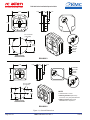
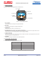
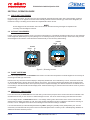
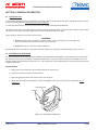
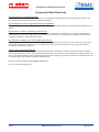
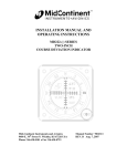
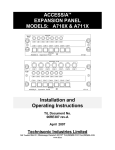
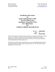
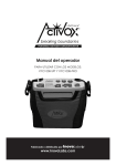
KMC PUBLICATION NO. 1401-1 RCA 2600 SERIES ELECTRIC DIGITAL HORIZON INSTALLATION/OPERATION GUIDE DI M 20 10 DI M 20 10 10 20 10 20 30 30 RCA 2600-3 P/N 102-0203-01-01 P/N 102-0203-01-02 RCA 2600-2 P/N 102-0202-01-01 P/N 102-0202-01-02 KMC KELLY MANUFACTURING COMPANY KELLY MANUFACTURING COMPANY 555 SOUTH TOPEKA WICHITA, KS 67202 Rev C (316) 265-6868 FAX (316) 265-6687 KELLYMFG.COM RCA 2600 Series Installation/Operation Guide KMC KELLY MANUFACTURING COMPANY TABLE OF CONTENTS SECTION 1 PAGE INSTRUMENT DESCRIPTION 3 1.1 General Description............................................................ 3 1.2 Physical Description............................................................ 3 1.3 Display Features................................................................. 5 1.4 Options and Configurations................................................. 5 SECTION 2 INSTALLATION 6 2.1 General Information............................................................ 6 2.2 Handling.............................................................................. 6 2.3 Pre-Installation Inspection................................................... 6 2.4 Installation........................................................................... 6 SECTION 3 SECTION 4 OPERATION 7 3.1 Pre-Flight Procedures.......................................................... 7 3.2 In-Flight Procedures............................................................ 7 3.3 Flight Limitations................................................................. 7 3.4 Emergency Procedures....................................................... 7 GENERAL INFORMATION 8 4.1 Instrument Care................................................................... 8 4.2 Optional Inclinometer.......................................................... 8 4.3 Frequently Asked Questions (FAQs)................................... 9 APPENDIX A DOD-160F ENVIRONMENTAL QUALIFICATION FORM 10 LIST OF ILLUSTRATIONS Figure 1.1, General Dimensions................................................... 4 Figure 1.2, Typical Display Features............................................. 5 Figure 3.1, Adjustment Controls.................................................... 7 Figure 4.1, Inclinometer Installation.............................................. 8 LIST OF TABLES Table 1.1, Leading Particulars....................................................... 3 Table 1.2, Options and Configurations.......................................... 5 REVISION DETAIL REVISION DATE A 08-23-2011 Initial Release B 09-06-2011 Updated Options and Configurations to table 1.2, page 5 C 08-15-2012 Added EASA conformance and view angle envelope to Table 1.1, page 3. Clarified Panel Tilt Angle on Table 1.2 page 5. Added Part 23 information to Section 2.1 page 6. Page 2 of 10 DETAIL KMC Publication No.1401-1 Rev C RCA 2600 Series Installation/Operation Guide KMC KELLY MANUFACTURING COMPANY SECTION 1: INSTRUMENT DESCRIPTION 1.1 GENERAL DESCRIPTION An attitude indicator, also known as a gyro horizon or artificial horizon, is an instrument used in an aircraft to inform the pilot of the orientation of the airplane relative to the earth. It indicates pitch (fore and aft tilt) and bank (side to side tilt), and is a primary instrument for flight in instrument meteorological conditions. Attitude indicators also have significant applications under visual flight rules. The RCA 2600 Digital Electronic Attitude Indicator receives digital information from a series of accelerometers which is processed to actuate a display that has two dimensions of freedom, simultaneously displaying pitch and bank. The display is colored to indicate the horizon as the division between the two colored segments (blue for sky and brown for ground), and is intended to be intuitive to use. The actual bank angle is calibrated around the circumference of the instrument dial. The pitch angle is indicated by a series of calibration lines, each representing 5° or 10° of pitch. Unlike digital multifunction type displays, the RCA 2600 display is not cluttered with additional information so that the pilot has instant attitude recognition. Because the RCA 2600 has no mechanical gyroscope, it is much more stable than traditional horizons. The unit is designed to work in 360 degrees of pitch and roll and, unlike a mechanical unit, the RCA 2600 can tolerate angles in pitch and roll that would cause a gyroscopic unit to tumble. On the attitude indicator you will see two yellow horizontal lines with a dot between them. The horizontal lines represent the wings and the dot represents the nose of the aircraft. If the symbolic airplane dot is above the horizon line (more blue background) - the aircraft is nose up. If the symbolic airplane dot is below the horizon line (more brown background) - the aircraft is nose down. When the dot and wings are on the horizon line, you are in level flight. If the lines representing the wings roll to the left or the right, the aircraft is probably starting a turn. 1.2 PHYSICAL DESCRIPTION The RCA 2600 indicator is a direct reading instrument which provides a visual display of aircraft pitch and roll in reference to the horizon. The instrument utilizes a series of accelerometers and complex mathematical formulas to determine pitch and roll. There is no external inputs to the instrument. Refer to table 1.1 below for leading particulars. There are two basic models of the RCA 2600 Series; the RCA 2600-2 which is the 2” version and the RCA 2600-3 which is the 3” version. OPERATING VOLTAGE........................................................................................................................................... 9 to 32VDC STARTING CURRENT............................................................................................................. 9VDC: 0.18 to 0.22 AMPs MAX RUNNING CURRENT ....................................................................................... (14VDC SYSTEM)...................0.20 AMP MAX (28VDC SYSTEM)...................0.15 AMP MAX CIRCUIT BREAKER SIZE............................................................................................................................................... 2 AMP SETTLING ERROR............................................................................................................ 1º MAXIMUM IN ROLL AND PITCH OPERATING TEMPERATURE RANGE..............................................................................................................-30º TO +50º C MATING CONNECTOR......................................................................................................... MS3116E8-4S OR EQUIVALENT WEIGHT ............................................................................................................ RCA2600-3............................................ 6.5 oz RCA2600-2............................................ 4.5 oz DIMENSIONS/PANEL CUTOUT........................................................................................................................ SEE FIGURE 1 EYE VIEWING ANGLE ENVELOPE.....................................................................Horizontal Left and Right: 35° Left, 35° Right Vertical Up and Down: 35° Up, 35° Down Minimum distance from display surface: 6 inches Maximum distance from display surface: 48 inches FAA SPECIFICATION CONFORMANCE........................................................... TS0-C4c, TSO-C113, DO-160F and DO-178B EASA SPECIFICATION CONFORMANCE.................................................................................... ETSO-C4c and ETSOC-113 MEETS OR EXCEEDS........................................................................................................................... AS8034A and AS396B TABLE 1.1, LEADING PARTICULARS Rev C KMC Publication No.1401-1 Page 3 of 10 KMC RCA 2600 Series Installation/Operation Guide 3.37 0.08 KELLY MANUFACTURING COMPANY 0.40 1.10 DIM 20 10 3.37 10 20 30 Ø 0.170 THRU (4 PLACES) A B DI M 1.237 (TYP) 3.17 20 10 2.474 (TYP) 10 20 A B C D 30 PANEL CUTOUT REAR MOUNTING GROUND 9-32 VDC SPARE SPARE RCA2600-3 2.75 0.12 1.10 0.40 GROUND 9-32 VDC SPARE SPARE A B C D DIM 20 2.40 D C 10 10 20 30 A B D C Ø 0.170 THRU (4 PLACES) 0.928 (TYP) 2.28 1.855 (TYP) DI M 20 10 10 20 30 NOTE • All dimensions in inches. • Mounting Hardware (both units) 6-32 screw - 0.5” plus panel thickness • Mating Connector (both units) MS3116E8-4S or equivalent. PANEL CUTOUT REAR MOUNTING RCA2600-2 Figure 1.1, General Dimensions Page 4 of 10 KMC Publication No.1401-1 Rev C RCA 2600 Series Installation/Operation Guide KMC KELLY MANUFACTURING COMPANY 1.3 DISPLAY FEATURES See Figure 1.2 below for typical display features. RCA 2600-3 shown. 1 ROLL POINTER DIM 6 PITCH DIAL 20 10 5 SYMBOLIC AIRPLANE 2 ROLL DIAL 3 HORIZON LINE 10 20 30 4 SLIP INDICATOR Figure 1.2, Typical Display Features 1. ROLL POINTER The Roll Pointer points to the degree of roll against the Roll Dial. 2. ROLL DIAL The Roll Dial shows the degree of roll against the Roll Pointer. 3. HORIZON LINE Indicates earth horizon relative to aircraft pitch and roll. 4. SLIP INDICATOR (Option available for the RCA2600-3 and RCA2600-2) Also referred to as an Inclinometer, the Slip Indicator measures the relative strength of the force of gravity and the force of inertia caused by a turn; thus indicating whether the aircraft is slipping or skidding. 5. SYMBOLIC AIRPLANE Represents the orientation of the aircraft’s wings and nose in relation to the horizon. The dot represents the nose of the aircraft and indicates Pitch. The wings indicate roll. 6. PITCH DIAL Indicates the Pitch angle as determined by the Symbolic Airplane dot. 1.4 OPTIONS AND CONFIGURATIONS For available options and configurations, refer to Table 1.2, below. Panel Tilt Angle setting Set to customer requirements Mating Connector MS3116E8-4S or equivalent Slip Indicator Optional add-on (order P/N 444-0010-01) Color Scheme Standard Blue & Brown Display pointer style Fixed Power Flag All models Brightness Adjust All models Table 1.2, Options and Configurations Rev C KMC Publication No.1401-1 Page 5 of 10 RCA 2600 Series Installation/Operation Guide KMC KELLY MANUFACTURING COMPANY SECTION 2, INSTALLATION 2.1 GENERAL INFORMATION The conditions and test required for the TSO approval of this article are minimum performance standards. It is the responsibility of those installing this article either on or within a specific type or class of aircraft to determine that the aircraft installation conditions are within the TSO standards. TSO articles must have a separate approval for installation in an aircraft. The article may be installed only if performed under 14CFR Part 43 or the applicable airworthiness requirements. For certain classes of Part 23 aircraft level C of DO-178B certification may not be sufficient - check with your local regulatory authority prior to installation. 2.2 HANDLING Although the RCA 2600 Series instruments are totally electronic, improper handling can cause damage. Please observe the following precautions while handling. 1. Do not drop, jar or shake instrument. Store instrument in shipping container until installation. 2. Instruments should be transported in the original shipping container when moved to and from aircraft. If container is not available, carefully carry by hand in upright position. 3. Avoid touching the screen. This is the most vulnerable part of the instrument. Improper handling and cleaning can cause permanent scratching of the screen surface (See Instrument Care on Page 8). 4. To prevent further damage, a malfunctioning instrument should be handled as carefully as a new instrument. Most malfunctioning instruments can be repaired and returned to service. Contact Kelly Manufacturing Company for repair and warranty information. 2.3 PRE-INSTALLATION INSPECTION 1. When the instrument is first received, inspect container for any shipping damage. 2. Carefully remove the instrument from shipping container and retain container for later storage or shipping. 3. Inspect the instrument for any signs of damage. Contact your Shipper to file any claim due to shipping damage. 4. Check labeling on the instrument to assure that the instrument panel tilt angle is correct for your aircraft. 2.4 INSTALLATION Install the instrument on the aircraft by using the aircraft manufacturer’s recommendations and by the following steps: 1. The RCA 2600 Series Horizon uses standard panel cutouts. Refer to figure 1.1 “General Dimensions” for instrument and cutout dimensions. 2. Instrument Pinout is: A = GND, B = PWR, C = SPARE, D = SPARE. Pinout information may also be found on the back of the instrument. See table 1.1 “Leading Particulars” for additional electrical information. 3. Attach aircraft electrical connector to the instrument and insert into the instrument panel cutout. 4. Secure instrument with user supplied screws. Use 6-32 UNC-2b screws or equivalent. Screw length should not exceed .5 inches plus bezel and panel thickness. Do not tighten. 5. With the aircraft on level surface, apply power to the instrument and allow it to warm up for 3 minutes. 6. Adjust roll position of the instrument by visually aligning the symbolic airplane with the horizon line as indicated on the instrument and tighten screws. -WARNING- Do Not modify the instrument in any way. Any modifications will void the warranty and revoke the FAA certifications. This includes, but is not limited to, actions such as enlarging the mounting holes. Page 6 of 10 KMC Publication No.1401-1 Rev C RCA 2600 Series Installation/Operation Guide KMC KELLY MANUFACTURING COMPANY SECTION 3, OPERATION GUIDE 3.1 PRE-FLIGHT PROCEDURES During pre-flight procedures, the instrument must be provided with adequate electrical power under normal vibration conditions (engine running). A red “X” appears across the screen indicating that the instrument is booting up. When the X disappears, the instrument is ready. The startup process should be completed within three minutes. NOTE On tail-dragger aircraft, the indicator will not show as level until after achieving level flight. No adjustment are necessary when level flight is achieved. 3.2 IN-FLIGHT PROCEDURES In flight, you do not need to cage the unit as you would a mechanical gyro. It will indicate accurately at all times. You may adjust the screen brightness (DIM button) at any time (See figure 3.1 for dimming controls). Press and hold up or down button until you reach desired brightness and release. Press both buttons simultaneously to reset to factory default setting. DIMMER DOWN UP DIMMER DOWN UP DIM 20 DIM 10 20 10 10 20 10 30 20 30 RCA 2600-2 RCA 2600-3 Figure 3.1, Dimming Controls 3.3 FLIGHT LIMITATIONS There are no flight limitations to the RCA 2600 Series horizon. The instrument will operate in a full 360 degrees of turn and may be used in light aerobatic type maneuvers. Extreme turns may cause the instrument display to temporarily disable itself. This is indicated by a red “X” across the screen and an “Exceed Bank Angle” warning notice at the bottom of the screen. The instrument should automatically reset the display within 3 to 10 seconds. This situation is due to the speed the processor repaints the display. The attitude sensors are not affected so it is not necessary to level the aircraft while the display resets. Unlike mechanical gyros, extreme maneuvers will not cause any harm to the instrument. 3.4 EMERGENCY PROCEDURES In the rare event that your RCA 2600 does not reset itself, you will need to pull power to the unit and reset the circuit breaker. This will restart the unit and you can continue on without damage to the unit. You do not need to be flying level while the unit resets. In a low voltage situation, the RCA 2600 will show a “Low Voltage” warning notice at the bottom of the screen. This notice will appear when the voltage goes below 11 volts. This notice will also indicated the amount of voltage the instrument is receiving. At 8.5 volts, a red “X” will appear across the screen indicating that the instrument reading is unreliable. It is recommended that you install the Kelly Manufacturing ESP-1 (Emergency Standby Power) backup battery unit. This will ensure that your instrument will have power in the event of Aircraft power failure. Contact your R.C. Allen/Kelly Mfg. distributor for additional information about this product. Rev C KMC Publication No.1401-1 Page 7 of 10 RCA 2600 Series Installation/Operation Guide KMC KELLY MANUFACTURING COMPANY SECTION 4, GENERAL INFORMATION 4.1 Instrument Care The most easily damaged part of your instrument is the screen. Special care should be taken when cleaning the screen to prevent scratches and other damage. Avoid touching the screen at all times. To clean light spots and dust, use a soft, lint free cotton cloth slightly moistened with distilled water. For harder to clean spots, use a 50/50 solution of isopropyl alcohol and distilled water. Vinegar may also be used in a 50% solution with water. You may also use cleaners approved for LCD TV’s and laptop computer screens. Always apply the cleaner to the cloth and not the screen. -CAUTION- ●● Do Not use paper towels, facial tissue or napkins. These products are made from recycled paper and may contain metals and wood chips that will scratch the screen. ●● Do Not use acetone or cleaners containing ammonia. By avoiding all screen contact and by using proper cleaning methods, the user will be rewarded with many years of service. 4.2 OPTIONAL SLIP INDICATOR An optional Slip/Skid Indicator (inclinometer)is available for the RCA2600-3 and RCA2600-2. The inclinometer can be purchased with the slip indicator at time of purchase or separately installed by the user (part number 444-0010-01). The addition of an inclinometer satisfies the requirements for FAA’s AC 91-75. The slip indicator may be attached before or after the instrument has been installed in the aircraft. INSTALLATION 1. Apply power to the instrument to assure that it reads level in pitch and roll. 2. Remove two screws on the face of the instrument. 3. Align Inclinometer with holes and replace screws. Do not tighten. 4. Adjust the Inclinometer until the bubble is centered and tighten screws just enough to secure Inclinometer. Do not over tighten. SLIP INDICATOR SCREWS M DI Figure 4.1, Inclinometer Installation Page 8 of 10 KMC Publication No.1401-1 Rev C RCA 2600 Series Installation/Operation Guide KMC KELLY MANUFACTURING COMPANY Frequently Asked Questions How long should my Digital Horizon last? There isn’t a good answer for this question. There are no moving parts in the RCA 2600 so there isn’t anything to wear out. The RCA 2600 should give hundreds of hours of trouble free operation. At what voltage level will my Digital Horizon become unreliable? Unlike mechanical horizons, the RCA 2600 doesn’t have a rotor that is affected by voltage. The RCA 2600 will be reliable from 9 to 32VDC. My instrument is showing a climb/dive, what can I do? You can check your aircraft owner’s manual or contact the aircraft manufacturer to determine if your aircraft’s instrument panel is tilted (pitched fore and aft). The tilt angle is any deviation from vertical of your instrument panel in level flight. Your instrument needs to be calibrated to compensate for this angle. My instrument is showing a turn in level flight, what can I do? It is very important to have the instrument level (left and right) in your panel. If the instrument is not level, it will show a turn when in level flight. To level the instrument place an “L” bubble level on the lip of the bezel at the bottom of the glass and adjust the instrument until the bubble is centered. How do I get my instrument repaired? For any overhaul or repair questions you can contact Kelly Manufacturing Company. Our Service Center can repair or refurbish any R.C. Allen instrument. The only thing really required is information. You can send us your instrument with a letter giving us your name, return shipping address, phone number and a brief description of what is wrong with the instrument or download a form from the Support page on our web site at: kellymfg.com/support.html. Email us for more information: [email protected]. Or, Visit our Web Site: kellymfg.com Rev C KMC Publication No.1401-1 Page 9 of 10 KMC RCA 2600 Series Installation/Operation Guide KELLY MANUFACTURING COMPANY APPENDIX A DO-160F Environmental Qualification Form NOMENCLATURE: ELECTRIC DIGITAL HORIZON MODEL NUMBER: RCA2600-series TSO NUMBER: C4c & C113 MANUFACTURERS SPECIFICATIONS: STP 1151 Rev. L (1/15/1996) MANUFACTURER: Kelly Manufacturing Company ADDRESS: 555 S. Topeka, Wichita, KS 67202 REVISION & CHANGE NUMBER OF DO-160: Rev. F dated 12/6/07 CONDITIONS Temperature and Altitude Low Temperature High Temperature Altitude Temperature Variation Humidity Operational Shocks and Crash Safety Vibration Explosive Atmosphere Waterproofness Fluids Susceptibility Sand and Dust Fungus Salt Fog Test Magnetic Effect Power Input Voltage Spike Audio Frequency Susceptibility Induced Signal Susceptibility Radio Frequency Susceptibility (Radiated and Conducted) Emissions of Radio Frequency Energy SECTION 4.0 4.5.1 4.5.2 & 4.5.3 4.6.1 5.0 6.0 7.0 8.0 9.0 10.0 11.0 12.0 13.0 14.0 15.0 16.0 17.0 18.0 19.0 20.0 21.0 Lightning Induced Transient Susceptibility 22.0 Lightning Direct Effects Icing Electrostatic Discharge Fire, Flammability 23.0 24.0 25.0 26.0 DATES TESTED: 9/08 – 5/11 DESCRIPTION OF TESTS CONDUCTED Equipment tested to Category D1 Equipment tested to Category C Equipment tested to Category A Equipment tested to Category B Equipment tested to Category U2 curve F & F1 Equipment identified as category X, no test performed Equipment identified as category X, no test performed Equipment identified as category X, no test performed Equipment identified as category X, no test performed Equipment identified as category X, no test performed Equipment identified as category X, no test performed Equipment tested to Category Z Equipment tested to Category BRX Equipment tested to Category A Equipment tested to Category Z Equipment tested to Category ZC Equipment tested for Radiated Susceptibility to Category T Equipment tested for Conducted Susceptibility to Category T Equipment tested to Category M Equipment tested to Pin Injection Test: Waveform A, Level 3 Cable Bundle Test: Waveform C, Level 3 Multiple Burst: no test performed (X) [A3C3X] Equipment identified as category X, no test performed Equipment identified as category X, no test performed Equipment tested to Category A Equipment identified as category X, no test performed REMARKS Page 10 of 10 In the power input test, equipment was tested to subparagraph 16.5.1.4 b, requirement for equipment with digital circuits KMC Publication No.1401-1 Rev C