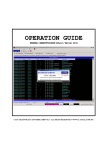
1
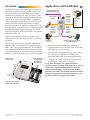
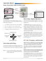
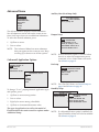
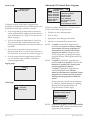
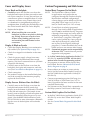
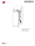
BAC-10000 Series
FlexStat™ BACnet Programmable Thermostats
Operation Guide
Contents
Overview................................................................. 2
Applications and Installation.................................... 2
Operation (Basic)..................................................... 3
Home, Main Menu, and Override Screens........... 3
Navigation........................................................... 3
Main Menu and Settings....................................... 3
Room Temp. Setpoint Adjustment........................ 3
H/C, Fan, Occupancy, and Override.................... 3
Configuration (Initial Setup).................................... 4
Main Menu Overview.......................................... 4
About the FlexStat................................................ 4
Advanced Menu................................................... 5
(Advanced) Application Options....................... 5
(Advanced) CB (Control Basic) Programs.......... 6
(Advanced) BACnet Communications............... 7
(Advanced) Date/Time...................................... 7
(Advanced) BACnet Device Properties.............. 8
(Advanced) Inputs............................................. 8
(Advanced) Temp. Setpoint Limits..................... 8
(Advanced) Motion Sensor................................ 8
(Advanced) Security Levels and Passwords........ 9
(Advanced) Trend Logs.................................... 10
(Advanced) Test............................................... 10
Alarms................................................................ 11
Date/Time.......................................................... 11
Schedules........................................................... 12
Setpoints............................................................ 13
System Setup...................................................... 13
Trend Viewer...................................................... 13
Resetting the FlexStat............................................. 14
Types of Reset..................................................... 14
Warm and Cold Starts........................................ 14
Restore Factory.................................................. 15
Network Connection.............................................. 16
BACnet MS/TP Network Communication....... 16
PC Data Port Connection................................ 16
BAC-10000 Series
Troubleshooting..................................................... 17
Alarm Issues....................................................... 17
Alarm, (False) Fan Fail..................................... 17
Alarm, (False) Low Limit (Freeze Stat)............. 17
Alarm, (False) Space Temp. or Humidity......... 17
Communication Issues....................................... 17
Firmware Upgrade Fails.................................. 17
KMD-5576 Communication Faulty................. 17
MS/TP Network Communication Faulty.......... 17
Cover and Display Issues.................................... 18
Cover Binds on Backplate............................... 18
Display Is Blank or Erratic............................... 18
Display Freezes (Buttons Have No Effect)....... 18
Custom Programming and Web Issues................ 18
Control Basic Programs Do Not Work............. 18
Custom Web Graphics Do Not Work.............. 18
Input, Sensor, and Value Issues........................... 19
Input Values Are Outside the Expected Range.19
Motion/Occupancy Sensor Does Not Work.... 19
Temperature Reading Is Incorrect................... 19
Temperature Setpoint Is Not Maintained........ 19
Output, Fan, and Relay Issues............................ 20
Analog Output Does Not Work....................... 20
Fan Does Not Run........................................... 20
Relay (Internal) Does Not Work...................... 20
Relay (External) Does Not Work..................... 21
Wiring Issues...................................................... 21
Maintenance.......................................................... 22
Firmware Upgrade................................................. 22
Programming (Custom).......................................... 22
Accessories............................................................ 22
Support.................................................................. 23
Important Notices.................................................. 23
Reference............................................................... 24
Acronyms and Abbreviations.............................. 24
Definitions of Terms........................................... 25
Index...................................................................... 26
Specifications, design, and operation1are subject to change without notice.
Operation Guide, Rev. J
Overview
Applications and Installation
The KMC FlexStat series of intelligent temperature/
humidity/occupancy-sensing, wall-mounted, thermostat/controllers are native BACnet Advanced
Application Controllers (B-AAC) for use in a BACnet system. The FlexStat simplifies networked zone
control for common packaged HVAC equipment,
such as packaged rooftop units, fan coil units, heat
pumps, and other similar applications. In addition, applications such as pressure dependent VAV,
terminal reheat, and medium-sized central station air
handling equipment applications may also be addressed through the on-board libraries of programs
built into the devices.
Communication with
Other BACnet Devices
Temperature
Sensing
3 Analog
Inputs
for Other
Sensors or
Contacts
The on-board library of programs permits rapid
configuration of a wide range of HVAC control applications.
24 Volts AC
Power
The FlexStat series also provides the capability to
customize the standard library of sequences using
KMC’s BACstage programming tool. This enables a
local authorized KMC installing contractor to adapt
the standard library to the unique site needs and application specific requirements of a particular project.
Dimensions in
inches (mm)
4.192 (1
06)
Optional
Humidity
and
Motion
Sensing
Up to 9
Outputs
(Analog
and/or
Relays)
Applications
• AHU
• FCU
• HPU
• RTU
Quick (Temporary) Network/
Programming Access
1. Wire the FlexStat’s backplate to the desired
equipment and set the FlexStat’s end-of-line and
input pull-up resistor switches.
2. Select the relevant application and options from
the (Advanced) Application submenu of the
Advanced Menu and other appropriate menus.
Terminal Blocks
on Removable
Backplate for
Easy Wiring
3. Configure the FlexStat for the BACnet network.
(See Network Connection on page 16.)
For general mounting and connection details,
including network wiring, EOL termination, power
connections, input/output connections, pull-up
resistor switch settings, see the relevant model’s
Installation Guide. For extended information about
wiring and sequences for specific applications, see
the BAC-10000 Series Application Guide.
5.551
(141)
1.125
(28.6)
EIA-485 Data Port for
Quick Network Access
BAC-10000 Series
2
Operation Guide, Rev. J
Operation (Basic)
Home, Main Menu, and Override Screens
Home Screen
WED 11/19
3:20 PM
COOL:
OCC:
Configuration Screens
FAN:
HUM: 36% RH
Setpoint
Override Screens
Override
Menu
FAN MODES
UNOCC: AUTO
OCC: AUTO
MAIN MENU
ABOUT
ADVANCED
ALARM
DATE/TIME
SCHEDULE
SETPOINTS
SYSTEM
Navigation
Room Temp. Setpoint Adjustment
Navigate the menus and change settings by pressing a combination of various arrow buttons and the
Enter button. Push the:
From the Home (temperature display) screen, press
the Up or Down arrow button once to view the existing setpoint.
• Enter button to select and/or exit value editing.
To temporarily change the setpoint, press the Up
or Down arrow button repeatedly until the desired
setting is displayed and press Enter. (If Enter is not
pressed, the display will return to the Home screen
after about five seconds and the new setpoint value
will still be saved.) The new setpoint will hold until
the next schedule change.
• Up or Down button to move among entries.
• Right or Left button to move among value fields.
• Left button to return to the Home screen.
To permanently change the setpoint for occupied
mode, go to the Setpoints section under the Main
Menu. (In the Setpoints menu, heating/cooling setpoints/setbacks and deadband can be changed with,
if required, the correct password access. See Setpoints on page 13.)
Up/Setpoint Button
Enter Button
Left/Override
Button
Right/Menu
Button
H/C, Fan, Occupancy, and Override
Down/Setpoint Button
When the fan is commanded to run, the animated
“FAN” icon rotates (if programmed to). When the
fan command stops, the fan icon is motionless.
Main Menu and Settings
From the Home (temperature display) screen, press
the Right arrow button to enter the Main Menu. You
may need to enter a password to change any settings.
The “OCC” icon shows a sun when in Occupied
mode and a quarter moon when in Unoccupied
mode.
HEAT or COOL will show (and be animated when
there is an active command), depending on the current mode. This can also be turned OFF.
NOTE: Access to the Main Menu, setpoint adjust,
and System/Occupancy/Fan override may
require a password.
BAC-10000 Series
To override these modes from the Home (temperature display) screen, press the Left arrow button.
Press Up or Down to get to the desired line and then
Enter (twice) to edit the mode setting. Press Left to
exit to Home.
3
Operation Guide, Rev. J
Configuration (Initial Setup)
About the FlexStat
NOTE: Menus shown in this document reflect
firmware version R1.3.0.4 or later. Actual
context-sensitive screens are dependent
on firmware version, FlexStat model, and
options selected.
NOTE: If
appear at the top of the screen
(such as in the Main Menu), scroll up or
down to see the rest of the menu’s offscreen choices.
ABOUT FLEXSTAT
FW: R1.3.0.0
BUILT: DEC 11 2009 @13:55:07
ASV: BAC_1xx63 R1.3.0.0 +6
MODEL: BAC–11163C
APP: AIR HANDLER
OPT: MOD H / MOD C
INSTANCE: 1
This display-only screen shows (scroll to see all):
• Firmware version (FW)
Main Menu Overview
• Build date
MAIN MENU
ABOUT
ADVANCED
ALARM
DATE/TIME
SCHEDULE
SETPOINTS
SYSTEM
• Application software version (ASV)
• Model number
• Application configuration and options (set in the
Application menu)
• Device instance (set in the Device menu)
Navigate the menus and change settings by pressing
a combination of buttons. Press the:
• MAC address (set in the Communications menu)
• Serial number
• Enter button to select and/or exit value editing.
• Board revision
• Up/Down button to move among entries (up/
down lines).
NOTE: ASV will show CUSTOM if any built-in
Control Basic program (1–5) is not running
or has auto-run disabled.
• Left/Right button to move among value fields
(left/right spaces).
• Left button to return to the Home screen.
NOTE: A log-in may be required to access menu
items.
SETPOINTS
SAVE CHANGE?
COOL SETPT:
HEAT SETPT:
67° F NO
YES
COOL SETBACK: 80° F
When prompted about a change (on any menu),
press Right/Left to select the desired choice and
then Enter.
BAC-10000 Series
4
Operation Guide, Rev. J
Advanced Menu
Auxiliary Heat (Heat Pump Only)
ADVANCED
APPLICATION
CB PROGRAMS
COMMUNICATION
DATE/TIME
DEVICE
INPUTS
LIMITS
AUX HEAT SETUP
AUX HEAT: COMP LOCKOUT
DELAY (MINS): 60
The Advanced Menu displays various submenus.
Not all submenus can be seen on the screen at one
time. Scroll up or down to see additional submenus.
To select the desired submenu, press:
Damper Setup
DAMPER SETUP
ECON: MODULATING
MIN POSITION (%): 10
CNTRL (0–100%): 2–10 V
ECON ENBLE TEMP: 55° F
LOW LIMIT ALARM: 45° F
1. Up/Down to move.
2. Enter to select.
NOTE: The Advanced Menu has more submenus
than can appear on the screen at once. Keep
scrolling up or down to see all the options.
NOTE: If the Economizer option is selected when
there is no mixed air temperature sensor
connected, a Low Limit Alarm will result.
See Alarms on page 11.
Fan Setup
(Advanced) Application Options
APPLICATION
DEGREES SCALE: °F
APP: FAN COIL
OPT: 4-PIPE
ADDITIONAL SETUP
FAN SETUP
SPEEDS: CONSTANT SPEED
OFF DELAY (SECS): 180
UNOCC: AUTO
OCC: AUTO
ADDITIONAL SETUP
DAMPER
FAN
HUMIDITY
SENSORS
VALVE
NOTE: For a Fan Fail Alarm, see Sensor Setup on
page 6 and Alarms on page 11.
Humidity Setup
To change ° F or C, preprogrammed application type,
and options, press:
HUMIDITY SETUP
DEHUMIDIFICATION DEHUMIDIFICATION
HUMIDIFICATION
DEHUM: ENABLE
1. Up/Down to move among entries.
2. Enter to select.
ALLOW HTG DEHUM: NO
DEHUM SETPT: 60%RH
DEHUM DEADBAND: 5%RH
3. Right/Left to move among value fields.
4. Up/Down to increment/decrement value.
The type of application (as well as the model of
FlexStat) affects the context-sensitive options under
Additional Setup.
BAC-10000 Series
NOTE: If a dehumidification option is enabled, the
Space Humidity Alarm will also be enabled.
See Alarms on page 11.
5
Operation Guide, Rev. J
(Advanced) CB (Control Basic) Programs
Sensor Setup
SENSOR SETUP
IN 2: DISCH AIR TEMP
CB PROGRAMS
PROG1: RUNNING
PROGRAM #1
PROG2: RUNNING PROG3: RUNNING SETPOINTS & MODES
PROG4: RUNNING AUTO-RUN: TRUE
PROG5: RUNNING CHANGE: READY
STATE: RUNNING
PROG6: HALTED
HALT REASON: NORMAL
PROG7: IDLE
HALT DESC:
OUT OF SERVICE: FALSE
The Input 2 sensor (AI2) can be configured for
discharge air temperature (Type III thermistor is the
default), fan status (dry contact), or unused.
To halt or load/run the built-in (1–5) and custom
(6–10) Control Basic programs, press:
• If set for discharge air temperature, the sensor
can be calibrated and changed from the default
Type III thermistor to a Type II. See (Advanced)
Inputs on page 8.
1. Up/Down to move among entries.
2. Enter to select.
3. Right/Left to move among value fields.
• If set for discharge air temperature, Trend Log
#2 is automatically created and monitors the
discharge air temperature, but it has no effect on
operation.
4. Up/Down to increment/decrement value.
NOTE: If custom Control Basic programs are
installed and a restore to factory settings
is performed, all factory programs are
restarted but all custom Control Basic
programs are halted. Change the state
of each program by loading/running the
program from the CB Programs menu (or
BACstage).
NOTE: If custom Control Basic programs are
installed and set to autorun, whenever the
firmware is updated, ALL (factory and
custom) programs are halted.
If custom Control Basic programs are
installed but NOT set to autorun,
whenever the firmware is updated, factory
programs are restarted but any (manual)
running custom programs are halted at
restart.
Change the state of each custom program
by using the Update Manager or loading/
running each program from the CB
Programs menu (or BACstage).
• If set for fan status and no closed contact is
detected when there is a call for fan operation, a
Fan Fail Alarm is created. See Alarms on page 11.
• If set for unused, built-in applications will not
use AI2, but the input would be available to
custom programming.
Staging Setup
STAGING
STG DELAY (MINS): 3
Valve Setup
VALVE SETUP
TYPE: 2–POSITION
ACTION: NRM OPEN
UPDATE MANAGER
PROGRAM CONFIG ERROR
ENABLE FACTORY: NO
ENABLE CUSTOM: NO
EDIT CB PROGRAMS
DONE
NOTE: Customized programs are the responsibility
of the user. KMC Controls does not provide
support for such programs.
BAC-10000 Series
6
Operation Guide, Rev. J
(Advanced) BACnet Communications
Sample Time Zones
COMMUNICATIONS
MAC ADDRESS: 1
BAUD RATE: 38400
MAX MASTER: 127
Offset to Equal UTC
Alaska
9 hours = 540 minutes
USA/Canada Pacific
8 hours = 480 minutes
Standard Time
USA/Canada Mountain 7 hours = 420 minutes
Standard Time
USA/Canada Central
6 hours = 360 minutes
Standard Time
USA/Canada Eastern
5 hours = 300 minutes
Standard Time
Bolivia, Chile
4 hours = 240 minutes
Argentina, Uruguay
3 hours = 180 minutes
United Kingdom,
0 hours = 0 minutes
Portugal
Europe (most countries) –1 hours = –60 minutes
Egypt, Israel, Turkey
–2 hours = –120 minutes
Kuwait, Saudi Arabia
–3 hours = –180 minutes
United Arab Emirates
–4 hours = –240 minutes
India, Sri Lanka
–5.5 hours = –330 minutes
China, Mongolia
–8 hours = –480 minutes
Korea, Japan
–9 hours = –540 minutes
New Zealand
–12 hours = –720 minutes
NOTE: The BACnet standard for this offset value
is: “The time zones to the west of the zero
degree meridian shall be positive values,
and those to the east shall be negative
values.” The value is in minutes, not hours.
To set parameters for BACnet MS/TP EIA-485
communications, press:
1. Up/Down to move among entries.
2. Enter to select.
NOTE: The Max Master is the highest MAC
address a device will attempt to locate
when polling for master devices on
the local network. To avoid possible
communication issues with the network
or a computer connected through a KMD5576 USB Communicator, the Max Master
number should be the lowest number
needed for that network.
(Advanced) Date/Time
DATE/TIME
DATE: APRIL 11 2009
TIME: 1:43:59 PM
UTC OFFSET: 300
DST ENABLE: TRUE
DST AUTO: TRUE
DST START:
>2ND SUN MAR 2:00 AM
To enter date and time information, press:
1. Up/Down to move among entries.
2. Enter to select.
3. Right/Left to move among value fields.
4. Up/Down to increment/decrement value.
For areas that observe Daylight Saving Time, select
True/On for DST ENABLE.
If the FlexStat is used in a BACnet network with UTC
(Coordinated Universal Time) synchronization (via
broadcasting or addressing a single thermostat) set
the UTC Offset value. The UTC Offset value is in
minutes and corresponds to the distance of the local
time zone to the zero degree meridian. In stand-alone
operation or networks that do not have UTC broadcasts, setting this value is not necessary.
BAC-10000 Series
7
Operation Guide, Rev. J
(Advanced) BACnet Device Properties
(Advanced) Temp. Setpoint Limits
DEVICE
INSTANCE: 1
LIMITS
OCC MIN CLG: 71° F
OCC MAX HTG: 76° F
UNOCC MIN CLG: 77° F
UNOCC MAX HTG: 65° F
NAME: FlexStat_101
LOCATION: KMC Controls
RESTART: NO
RESTORE FACTORY: NO
To set the BACnet device instance, name, and
location, press:
To set the minimum and maximum allowed user/
operator setpoint values, press:
1. Up/Down to move among entries.
1. Up/Down to move among entries.
2. Enter to select.
2. Enter to select.
The FlexStat can also be restarted or restored to
factory defaults from this menu. See Resetting the
FlexStat on page 14 for more information about that
function.
3. Right/Left to move among value fields.
4. Up/Down to increment/decrement value.
(Advanced) Motion Sensor
(Advanced) Inputs
1:
2:
3:
4:
4:
MOTION SENSOR
MOTION OCC: ENABLE
STATE: OCCUPIED
INPUTS
SPACE TEMP
DISCH AIR TEMP
MIXED AIR TEMP
INPUT #2
OUTSIDE AIR TEMP DISCH AIR TEMP
SPACE HUMIDITY
VALUE: 60.0° F
CAL. OFFSET: 0.0
OUT-OF-SERVICE: FALSE
SENSOR: 10K TYPE III
In BAC-11xxx models, a motion/occupancy sensor
may be enabled to trigger occupancy override.
During scheduled “off” times, the motion sensor will
start occupancy override (for 1 hour as a default)
when it detects motion. Occupancy override will end
(with the default setting) 1 hour after motion was
last detected. The length of occupancy override is
configurable in the System menu. See System Setup
on page 13.
Inputs vary according to model, selected application,
and selected application options. See (Advanced) Application Options on page 5.
To change sensor type and calibration offset, press:
1. Up/Down to move among entries.
2. Enter to select.
To enable/disable or monitor the motion/occupancy
sensor (if installed), press:
3. Right/Left to move among value fields.
1. Enter to select.
4. Up/Down to increment/decrement value.
2. Right/Left to move among value fields.
Value will show a temperature reading or a voltage
(0.0 to 3.0), depending on the sensor. Analog sensors
can be calibrated using the Calibration Offset option.
3. Up/Down to increment/decrement value.
BAC-10000 Series
The State field monitors whether motion has been
detected during the last scan of the motion sensor
input (BI6). Detected motion will show an “occupied” state. This can be used during troubleshooting
to determine if motion is being detected.
8
Operation Guide, Rev. J
(Advanced) Security Levels and Passwords
To enter an alphanumeric password at the prompt:
SECURITY
ACCESS LEVELS
PASSWORDS
ACCESS LEVELS
SETPOINT ADJ: NONE
MAIN MENU: ADMIN
SYSTEM MODE: OPER
OCC OVERRIDE: USER
FAN OCC/UNOCC: OPER
1. Up/Down to move.
2. Enter to select.
PASSWORDS
USER:
1000
OPERATOR:
1234
ADMIN:
5678
3. Up/Down to increment/decrement value.
The required password level is specified in the
prompt.
For additional security and protection from
vandalism, install the FlexStat inside a third-party
locking thermostat guard/cover (but proper airflow
must be maintained).
Access to the Main Menu, Setpoint Adjust, and
System/Occupancy/Fan settings have a default
password level of User. This level can be changed for
each function to None, Operator, or Administrator
through the Access Levels menu. Passwords are set
in the Passwords menu.
Menu Items Access Levels
Menus
Home Screen
Any person can view the display but might not be
able to change any settings without logging in with
one of the three levels of passwords:
• None (Level “0”): No password is required
(everyone has access).
User Operator Administrator
* = Selectable, Default is User
Setpoint Adjust (Up/Down)
x*
x*
x*
System Mode (Auto/Heat/Cool/Off)
x*
x*
x*
Occupancy Override (On/Off)
x*
x*
x*
Fan Modes (Auto/On/Off)
x*
x*
x*
x
x
x
Main Menu* (Default is User)
• User (Level 1): See the Menu Items Access Levels
chart.
About
Advanced
x
x
• Operator (Level 2): See the Menu Items Access
Levels chart.
Alarm
x
x
Date/Time
x
x
• Administrator (Level 3): Can access all menus
and change all editable values. DO NOT
FORGET THIS PASSWORD!
Schedule
x
x
Setpoints
x
x
System
x
x
x
x
Trend Viewer
NOTE: Setting a password to (the default) 0000
eliminates the password prompt and
allows full access for that level. If no
password is set for ADMIN, no password
prompt will occur. If any password is set
for ADMIN, the menu items accessible
at the various levels are shown in the
following chart.
NOTE: Changes in security levels and/or
passwords take effect when the current
Administrator log-in has timed out. Logins last until 60 seconds (default) after
the last button press. Desired length of
inactivity time-out can be changed in the
Systems submenu.
NOTE: When setting a password, the Up button
increases the alphanumeric value (0
through 9 and then A through Z). The
Down button decreases the value. DO NOT
FORGET THE ADMIN PASSWORD!
BAC-10000 Series
x
Advanced Menu
Application
x
Additional Setup
x
Control Basic Programs
x
Communication
Date/Time
x
x
x
Device
x
x
Inputs
x
x
Limits
x
x
Motion Sensor
x
x
Security
x
Trend Logs
x
x
Test
x
x
This chart shows conditions in which an administrator password is set
(is not 0000) and default password levels are used.
9
Operation Guide, Rev. J
(Advanced) Trend Logs
TREND LOGS
TREND 1: TRUE
TREND 2: TRUE
TREND 3: FALSE
TREND 4: FALSE
TREND 5: FALSE TREND #1
TEMPERATURE LOG
TRENDSPACE
6: FALSE
REF: AI1
TRENDOBJECT
7: FALSE
LOG ENABLE: TRUE
INTERVAL (MINS): 10
STOP W/FULL: FALSE
TL
RESET COUNT: NO
APR17
COUNT: 256
APR17
TOTAL CNT: 613
APR17
VIEW LOG BUFFER
APR17
APR17
APR17
APR17
(Advanced) Test
TEST
LCD/KEY TEST
The test menu merely tests the display’s pixels and
key functions.
#1–SPACE TEMP
1:27PM, 71.4
2:27PM, 71.5
3:27PM, 71.6
4:27PM, 71.8
5:27PM, 76.3
6:27PM, 81.2
7:27PM, 82.3
1. Up/Down to move among entries.
2. Enter to select and exit.
NOTE: Space temperature (AI1) is the default trend
log #1. If AI2 is configured for discharge air
temperature, that will become the default
trend log #2. See Sensor Setup on page 6.
To set the desired object to track, press:
1. Up/Down to move among entries.
2. Enter to select.
The trend log buffer may be viewed by scrolling
down and selecting View Log Buffer. The buffer may
also be viewed from the Main Menu by scrolling
down to the Trend Viewer (see page 13).
NOTE: The BACnet standard for log intervals
is hundredths of seconds. The simplified
display on the FlexStat converts the value
to minutes. However, BACstage™ and
TotalControl® do display hundredths of
seconds but in different ways. For a “10”
(minute) interval on a FlexStat display,
TotalControl would show “00:10:00.00”
(hours:minutes:seconds.hundredths of
seconds) and BACstage would show
“60000” (hundredths of seconds) instead.
NOTE: If applicable to the model, the humidity
sensor is AI5 and the motion sensor is
BI6, which can also be configured for trend
logs. See the BAC-10000 Series Application
Guide (P/N 913-019-03) or relevant BAC10000 Series Installation Guide for other
desired input and output objects in an
application.
BAC-10000 Series
10
Operation Guide, Rev. J
Alarms
SAT 4/11
Date/Time
3:20 PM
DATE/TIME
DATE: APR 11 2009
TIME: 1:43:59 PM
ALARMS
COOL:
* SPACE
TEMP ALARM 04/11
SERVICE
OCC:
FAN:04/11/09 08:37:56
<AI1>
SPACETEMP
HUM: 20%RH
PRESENT VALUE = 90.1
EXCEEDS HIGH_LIMIT
<EE1>
SPACETEMPALARM
DELETE ALARM?
YES
To enter date and time information (only), press:
NO
1. Up/Down to move among entries.
A flashing “SERVICE” on the Home screen indicates
an alarm. To view and delete alarms, press:
2. Enter to select.
3. Right/Left to move among value fields.
1. Right to move among fields.
4. Up/Down to increment/decrement value.
2. Enter to select. (Enter on Alarm Details screen to
delete the alarm.)
More options (such as UTC offset and daylight saving time options) are available in the (Advanced)
Date/Time menu (see page 7).
3. Left to go back one page.
Built-in alarms are triggered under these conditions:
• Space Temp Alarm—temperature outside the
range of 56 to 86° F for over 300 seconds.
• Space Humidity Alarm—humidity above 65%
for over 300 seconds. This is available only in
FlexStat models with a humidity sensor and a
dehumidification option selected in the Humidity setup). See Humidity Setup on page 5.
• Fan Fail Alarm—no fan status signal within five
seconds of call for fan (and Input 2 is configured
for the fan status sensor option). See Sensor Setup
on page 6.
• Low Limit Alarm (freeze stat)—space
temperature is below the adjustable (under
Damper Setup) low limit alarm temp for one
second (when configured for the economizer
option). After a low limit alarm is generated,
the fan will not run until after the FlexStat
is restarted. See Restart under Resetting the
FlexStat on page 14. See also Damper Setup on
page 5.
(Up to six additional alarms may be added with
custom programming.)
NOTE: Time delays and limits can be modified in
the corresponding Event Enrollment objects
using TotalControl.
BAC-10000 Series
11
Operation Guide, Rev. J
Schedules
SCHEDULE
WEEKDAYS [MON–FRI]
WEEKEND [SAT–SUN]
ENTIRE WEEK [MON–SUN]
INDIVIDUAL DAYS
HOLIDAYS
HOLIDAYS
HOL1: JAN 1 2009
HOL2: MAR 21 2009
HOL3: MAY 26 2009
HOL4: JULY 4 2009
HOL5: SEPT 1 2009
HOL6: NOV 27 2009
HOL7: NOV 28 2009
To select the desired schedule, press:
The Holiday entries will override the normal
occupied weekly schedule entries and keep those
days’ settings at their setback values. Setback
values are entered in the Setpoints section of the
Main Menu. (See also the maximum and minimum
setpoint values in the Limits section of the Advanced
Menu.)
1. Up/Down to move among entries.
2. Enter to select.
3. Left to go back one page.
WEEKDAYS
1: 7:30:00 AM ON
2: 5:15:00 PM OFF
3:
4:
5:
6:
[—>] DELETES ENTRY
To enter upcoming holidays, press:
1. Up/Down to move among entries.
2. Enter to select.
3. Right/Left to move among value fields.
4. Up/Down to increment/decrement value.
To enter weekly schedules for occupied (ON) and
unoccupied (OFF) times, press:
1. Right/Left to move among days and Enter to
select.
2. Up/Down to move among entries and Enter to
select and edit.
3. Right/Left to move among value fields.
4. Up/Down to increment/decrement value.
5. Enter to exit value editing.
6. Left to move back to days or back one page.
BAC-10000 Series
12
Operation Guide, Rev. J
When Display Blanking is enabled (Y), the display
turns off at the same time the backlight goes off
(after reset, initial power-up, or time-out). When any
button is pressed, the display will reappear until the
time-out is reached again.
Setpoints
SETPOINTS
COOL SETPT: 74° F
HEAT SETPT: 67° F
COOL SETBACK: 80° F
HEAT SETBACK: 64° F
MIN SETPT DIFF: 2° F
DEADBAND: 2° F
DEHUM SETPT: 60 % RH
The menu/display/backlight time-out (seconds
since the last button is pushed) is set in Inactivity.
Access to the Main Menu, setpoint adjust, and
System/Occupancy/Fan override have a default
password level of User. This level can be changed for
each function to None, Operator, or Administrator
through this screen. Passwords are set in the (Advanced) Passwords menu. See (Advanced) Security
Levels and Passwords on page 9.
In the Setpoints menu, deadband, setbacks, and
setpoints for various values are set. (The room
temperature setpoint can also be manually changed
from the Home menu.)
To adjust the setpoints, press:
1. Up/Down to move among entries.
Trend Viewer
2. Enter to select.
3. Up/Down to increment/decrement value.
1:
2:
3:
4:
5:
6:
7:
System Setup
SYSTEM
SYSTEM ENABLE: AUTO
OCC OVRIDE (HRS): 1.0
INACTIVITY (SECS): 60
DISPLAY BLANKING: NO
TREND VIEWER
SPACE TEMP
SPACE HUMIDITY FAN
COOL 1
COOL 2
TL
APR11
APR11
APR11
APR11
APR11
APR11
APR11
34
27
19
18
21
#1 SPACE TEMP
1:27PM, 70.3
2:27PM, 71.3
3:27PM, 71.6
4:27PM, 71.8
5:27PM, 76.3
6:27PM, 81.2
7:27PM, 82.3
To adjust the system configuration values, such as
system enable (auto, off, heat, or cool), occupancy
override time, and display inactivity time-out:
To view trend log buffers, press:
1. Up/Down to move among entries.
2. Enter to select.
2. Enter to select.
Trend logs are set up in the (Advanced) Trend Logs
menus (see page 10).
1. Up/Down to move among entries.
3. Up/Down to increment/decrement value.
Occupancy Override on this menu is the amount of
time (in hours) a manual change in the setpoint (via
the Up and Down buttons) will be allowed to override the scheduled setpoint. When the time is set to
0, the override state will last until the next schedule
change.
BAC-10000 Series
13
Operation Guide, Rev. J
Resetting the FlexStat
Types of Reset
• Restarts the controller’s Control Basic programs.
If the FlexStat is not operating correctly or if a low
limit alarm has occurred, the FlexStat should be
reset (reinitialized). Any reset interrupts normal operation, and three types of reset exist:
• Leaves configuration and programming intact.
NOTE: Menu changes may take up to about two
minutes to write to nonvolatile Flash
memory. If power to the FlexStat is lost
during this time, changes may be lost.
Restarting the FlexStat from its menu,
TotalControl, or BACstage are the
recommended methods.
NOTE: When power is restored after an outage,
the FlexStat will attempt to do a warm
start as long as the values in RAM are
retained (up to about four hours). If
the the RAM checksum test fails, a cold
start will be done instead. (In custom
Control Basic programming, using the
POWERLOSS command may be desirable
to determine start-up conditions and to take
appropriate actions—see the Help system
in TotalControl or BACstage for more
information.)
• A warm start is generally the least disruptive option (restarting normal operation the quickest).
• If problems still persist, try a cold start. (This
should also be used after a new Control Basic
program is loaded and compiled.)
• If problems still persist (or major changes in a
firmware update have taken place) restoring factory defaults (and reconfiguring and reprogramming the FlexStat) may be required.
Warm and Cold Starts
CAUTION
During a restart, the analog outputs go to zero,
and relays go to their normally open state. A restart is a process that lasts around ten seconds,
and it may result in several changes of state
for an output, turning equipment off and on
abruptly. Before resetting the FlexStat, manually
override equipment as needed. If a large fan
is controlled by the FlexStat, for example, set
a minimum off time. See Fan Setup on page 5
(built-in, selectable applications with compressors have a default programmed minimum off
time of 300 seconds).
ADVANCED
APPLICATION
CB PROGRAMS
COMMUNICATION
DATE/TIME
DEVICE
LIMITS
SECURITY
DEVICE
INSTANCE: 1
NAME: FlexStat_101
LOCATION: KMC Controls
RESTART: WARM START
RESTORE FACTORY: NO
A warm start does the following in the FlexStat:
To perform a WARM start, do one of the following:
• (After zeroing out objects during the restart
process) restores present values of objects to
their last values before the restart (until they are
updated by the FlexStat’s programs).
• From the FlexStat menu, select Advanced > Device > Restart > Warm Start.
• From TotalControl or BACstage, select Reinitialize Device > Warm Start.
• Restarts the controller’s Control Basic programs.
• Momentarily remove power to the FlexStat.
• Leaves configuration and programming intact.
To perform a COLD start, do one of the following:
CAUTION
• From the FlexStat menu, select Advanced > Device > Restart > Cold Start.
If the checksum test in RAM fails during a warm
start, a cold start is performed instead.
• From TotalControl or BACstage, select Reinitialize Device > Cold Start.
A cold start does the following in the FlexStat:
• (After zeroing out objects during the restart
process) returns all object values to their relinquished defaults (until they are updated by the
FlexStat’s programs).
BAC-10000 Series
14
Operation Guide, Rev. J
Restore Factory
Restore Factory (restoring the FlexStat to the factory
settings) does the following:
CAUTION
After a return to factory defaults, applications are
unconfigured. You must select the desired application and appropriate settings before connected
equipment will operate properly. (See (Advanced)
Application Options on page 5.)
• Clears present values.
• Restores the object database/configuration to the
defaults.
• Restarts the controller’s (factory installed) Control Basic programs.
To restore the FlexStat to factory settings:
1. Select Restore Factory from the Advanced > Device menu.
NOTE: The MAC address and device instance are
not restored to their original defaults, and
custom Control Basic programs are not
deleted. If custom Control Basic programs are
installed, all factory programs are restarted
but all custom Control Basic programs are
halted. Custom programs may be restarted by
loading/running the programs from the CB
Programs menu. See (Advanced) CB (Control
Basic) Programs on page 6.
2. When prompted for the required restart, press
Enter. (To Cancel, press the right button and then
Enter or just let the display time-out).
3. After the FlexStat has restarted, review the settings and reconfigure as needed.
ADVANCED
APPLICATION
DEVICE
CB PROGRAMS INSTANCE: 1
COMMUNICATION
RESTART REQUIRED!
DATE/TIME
NAME: FlexStat_101
DEVICE
LOCATION: KMC Controls
RESTART CANCEL
LIMITS
SECURITY
RESTART: NO
CAUTION
When returned to factory defaults, analog outputs will go to zero and relays will go to their
normally open state. Before restarting the thermostat, manually override equipment as needed.
BAC-10000 Series
RESTORE FACTORY: YES
15
Operation Guide, Rev. J
Network Connection
BACnet MS/TP Network Communication
PC Data Port Connection
Connect the network wiring and set the EOL switches accordingly. (See the Installation Guide for wiring
and end-of-line switch information.)
The FlexStat is equipped with a PC data port located
at the bottom of the thermostat housing. This port
provides a temporary EIA-485 (formerly RS-485)
connection to the digital network for network setup
or troubleshooting.
From the FlexStat menus, adjust the device instance
number, the MAC address, and baud rate from the
defaults as necessary. Set the Max Master to the
minimum necessary for the network. See (Advanced)
BACnet Device Properties on page 8 and (Advanced)
BACnet Communications on page 7.)
To connect a computer to the port, a means of
converting the EIA-485 signal to a USB or EIA-232
(formerly RS-232) signal will be needed. For USB,
use a KMC KMD-5576 USB Communicator. For
EIA-232, use a third-party interface. (See the instructions included with those devices and software.) To
connect to the PC data port:
NOTE: The current FlexStat MAC address and
device instance numbers can be viewed in
the About menu. Each BACnet device on a
network must have a unique MAC address
and device instance.
1. Connect the keyed, flat end of the KMD-5624
interface cable (included with the KMD-5576) to
the port on the bottom of the FlexStat.
2. Connect the modular plug of the cable to the
interface device that converts the EIA-485 signal
from the FlexStat into a USB or EIA-232 signal.
3. Connect the suitable cable from the interface
device to the computer’s serial or USB port.
Install any required software and configure the
port as necessary.
NOTE: To avoid faulty communication with the
KMD-5576 USB Communicator, the Max
Master number may need to be reduced
to the minimum required for the network
and the driver and latency settings on
the computer may need to be checked or
updated. See Troubleshooting on page 17.
KMD-5576
KMD-5624
Cable
BAC-10000 Series
16
Operation Guide, Rev. J
Troubleshooting
Alarm Issues
Communication Issues
Alarm, (False) Fan Fail
Firmware Upgrade Fails
• Check configuration. Be sure the Fan Status
option is not selected when there is no sensor/
switch for it.
• Ensure the WD (watch dog) jumper is temporarily removed during the upgrade process (see the
KMD-5699 Installation Guide, P/N 913-019-04).
Reinstall the pin on the left and center pins after
the upgrade process is complete.
• Check that the IN2 (fan status) input pull-up
resistor switches are fully latched in the correct
positions. Any passive, dry contact should use
the 10K Ohm setting. (See the Connections and
Wiring section of the relevant BAC-10000 Series
Installation Guide.)
• Check connections.
• Ensure firmware for the correct model is selected
in the Firmware Upgrade Tool.
NOTE: If firmware for a wrong model is accidentally installed, the outputs will not match the
applications/configuration on the display.
NOTE: Backing up the existing settings and
firmware image before or during the
upgrade process is good practice.
NOTE: Restoring to the factory defaults and
reconfiguring might be needed if how the
FlexStat operates changes. Read all notes
accompanying the firmware update!
• Check IN2 (fan status) input wiring.
• Check the connected fan status sensor/switch.
• Using BACstage or TotalControl, check that AI2
(fan status) is not configured as “Out Of Service.”
Alarm, (False) Low Limit (Freeze Stat)
• Check the Low Limit Alarm setting—see Damper
Setup on page 5.
• Check configuration. Be sure the Economizer
option is not selected when there is no mixed air
temperature sensor.
KMD-5576 Communication Faulty
• Upgrade to the latest version of BACstage (ver.
2.4.0.25 or later required).
• Check that the IN3 (mixed air temp.) input
pull-up resistor switches are fully latched in the
correct positions (see the Connections and Wiring
section of the relevant BAC-10000 Series Installation Guide).
• Check the settings for the USB port on the
computer (Device Manager > Ports) and the
MS/TP port in BACstage (Access > Connection
Parameters).
• Check IN3 (mixed air temperature) input wiring.
• Reduce the Max Master number down to the
minimum needed for that network—see (Advanced) BACnet Communications on page 7.
• Check the connected mixed air temperature sensor.
• Using BACstage or TotalControl, check that AI3
(mixed air temp.) is not configured as “Out Of
Service.”
• Install latest driver and check latency settings.
See Latency Settings for KMD-5576 Service Bulletin (SB0308A) on the KMC web site.
NOTE: After a low limit alarm is generated, the
fan will not run until after the FlexStat
is restarted. See Resetting the FlexStat on
page 14.)
• See also MS/TP Network Communication Faulty
below.
MS/TP Network Communication Faulty
Alarm, (False) Space Temp. or Humidity
• Reduce the Max Master number down to the
minimum needed for that network—see (Advanced) BACnet Communications on page 7.
• See Alarms on page 11.
• See Temperature Reading Is Incorrect on page 19.
• See Temperature Setpoint Is Not Maintained on
page 19.
• Check that EOL switches are fully latched in the
correct positions (see the relevant BAC-10000
Series Installation Guide).
• Using TotalControl, adjust the limits or time
delay.
• Check MAC address and device instance numbers.
• Check baud rate.
BAC-10000 Series
17
Operation Guide, Rev. J
Cover and Display Issues
Custom Programming and Web Issues
Cover Binds on Backplate
Control Basic Programs Do Not Work
• Carefully remove the FlexStat cover from the
backplate and inspect for bent pins and/or terminal socket connectors. If cover pins are bent, use
a needle-nose pliers to straighten them. If socket
connectors are bent, use a pointed object (such
as a thumbtack or straightened paperclip) to
straighten them. (Pushing the pointed object into
the socket from the back side can be helpful.)
NOTE: The FlexStat has a library of builtin applications and options that are
configured through the FlexStat’s display.
Beyond these standard configurations,
custom changes can be added to a FlexStat
using KMC’s BACstage (ver. 2.4.0.26 or
later) or TotalControl (ver. 2.0.5 or later).
NOTE: Control Basic (read-only) programs 1
through 5 are used for built-in applications
and can not be modified directly. Programs
6 through 10 are empty and can be used for
additional programming. Using BACstage
or TotalControl, a program (1 through 5)
can be copied, pasted into a new program
code object (6 through 10), edited, and
run in place of the original. (Although
programs 1–5 cannot be edited, they can be
halted and set to not autorun after restart.)
NOTE: Customized programs are the responsibility
of the user. KMC Controls does not provide
support for such programs.
• Replace the backplate.
NOTE: When installing the cover on the
backplate, be sure to not pinch or dislodge
any wiring. Do not use excessive force.
If there is any binding, pull out cover
and examine pins and terminal socket
connectors.
Display Is Blank or Erratic
• Check that Display Blanking is not unintentionally enabled. (See System Setup on page 13.)
• Check for a tripped circuit breaker to the transformer.
• In the BAC-10000 Series Application Guide (P/N
913-019-03), carefully REVIEW ALL the information in the Custom Programming section!
• Check for proper supply voltage from transformer and that the transformer has enough
capacity (VA) for all connected devices (see their
respective data sheets).
• Set programs to autorun and/or check if they
have halted. Review (Advanced) CB (Control
Basic) Programs on page 6.
• Carefully remove the FlexStat cover from the
backplate, check pins and connectors, and reinsert. (See Cover Binds on Backplate on page 18.)
• Ensure objects are written to correct priority
levels. See the Custom Web Graphics section in
the BAC-10000 Series Application Guide (P/N
913-019-03).
• Check connections.
• Put another FlexStat on the installed backplate,
and if the second FlexStat functions properly,
replace the first FlexStat.
• Custom programming requires BACstage (ver.
2.4.0.26 or later) or TotalControl (ver. 2.0.5 or
later). Upgrade to the latest version for the most
complete functionality.
Display Freezes (Buttons Have No Effect)
• Carefully remove the FlexStat cover from the
backplate and ensure the WD (watch dog)
jumper (near the bottom of the board) is installed
on the left and center pins. The jumper is temporarily removed during a firmware update and
should be reinstalled when the process is completed. (See the KMD-5699 Installation Guide,
P/N 913-019-04, for more information.) Reinstalling the cover on the backplate will restart the
FlexStat.
BAC-10000 Series
• For assistance with Control Basic commands, see
the Help system in TotalControl or BACstage.
Custom Web Graphics Do Not Work
• In the BAC-10000 Series Application Guide (P/N
913-019-03), review the Custom Web Graphics
section.
• See also Control Basic Programs Do Not Work
above.
18
Operation Guide, Rev. J
Input, Sensor, and Value Issues
• Connect remote motion sensors to an input
(requires custom programming).
Input Values Are Outside the Expected Range
• Check that ALL the input pull-up resistor
switches are fully latched in the correct positions.
See the Connections and Wiring section of the
relevant BAC-10000 Series Installation Guide. A
single incorrect switch position may affect multiple inputs. All input switches must be latched
in either 10K Ohm or 0–12 VDC positions even
if no input is connected! Input switch pairs (3-4,
5-6, and 7-8) must never have both switches set
to the left or both to the right—if switch 3 is set
to the left, for example, 4 must be set to the right
(or vice versa).
• For more information on detection performance,
patterns, configuration, programming, and other
issues, see the Motion/Occupancy Sensor section
in the BAC-10000 Series Application Guide.
Temperature Reading Is Incorrect
• After applying power for the first time (or after
an outage), allow the FlexStat to self-calibrate a
few minutes before verifying temperature reading.
• If the discrepancy is small, adjust the calibration
offset—see (Advanced) Inputs on page 8.
• Check that the correct input type is selected on
the Inputs screen. A Type III thermistor is the
default on IN2 through IN4. See (Advanced)
Inputs on page 8.
• Check that the thermistor is centered in its hole at
the bottom of the case and has an air gap around
it. Also check that its leads are not pinched,
shorted, or broken and that the tape holding
down the leads is not loose. (Some early models
with humidity sensors did not have the additional thermistor—temperature was derived from
the same chip that measured humidity.)
• Check input wiring. See Wiring Issues on page 21.
• Check connected sensors.
• Using BACstage or TotalControl, check that the
input is not configured as “Out Of Service.”
• Restore the FlexStat to factory settings (see Resetting the FlexStat on page 14) and reconfigure.
• Using BACstage or TotalControl, check that
AI1 (space temp.) is not configured as “Out Of
Service.”
Motion/Occupancy Sensor Does Not Work
• Check that the FlexStat is not mounted on an
outside wall, is not exposed to heat sources or
sunlight, is not exposed to drafts from windows
or air vents, or is not blocked from normal air
circulation.
• The initial firmware (R.1.0.0.0 and earlier) did not
support this sensor within the built-in selectable
programs. Custom programming was required—
see the BAC-10000 Series Application Guide, P/N
913-019-03. Upgrade to the latest firmware for
built-in support.
• See also Input Values Are Outside the Expected
Range on page 19.
• After an initial power-up or restart, the motion/
occupancy sensor requires about 30 seconds
before it will begin responding to motion.
Temperature Setpoint Is Not Maintained
• Select Occupied mode from the Home Menu—
see H/C, Fan, Occupancy, and Override on page 3.
• The motion/occupancy sensor initiates override
only during “off” times in the schedule. See
Schedules on page 12.
• Override the fan to On from the Home Menu—
see H/C, Fan, Occupancy, and Override on page 3.
• Check that the motion sensor is enabled and
detects motion. See (Advanced) Motion Sensor on
page 8.
• Check that the appropriate application is selected—see (Advanced) Application Options on
page 5.
• Using BACstage or TotalControl, check that BI6
(occ status) is not configured as “Out Of Service.”
• Check that room temperature is being sensed
correctly—see Temperature Reading Is Incorrect
on page 19.
• The FlexStat must be installed where there is a
clear view of typical traffic area (reliable range is
out to about 33 feet). Remove or move obstacles.
Reinstall the FlexStat in a more optimal location
if necessary.
BAC-10000 Series
19
Operation Guide, Rev. J
Output, Fan, and Relay Issues
Fan Does Not Run
Analog Output Does Not Work
NOTE: The animated fan icon is coupled with
BV18 in the packaged programming (not
the actual fan output terminal).
• Select Occupied mode from the Home Menu—
see H/C, Fan, Occupancy, and Override on page 3.
CAUTION
Do not mistakenly connect 24 VAC to an analog
output ground. This is not the same as a relay’s
switched common. See the backplate’s terminal
label for the correct terminal.
NOTE: The maximum current of an analog output
is 20 mA @ 12 VDC. Excessive loads will
be clamped at the maximum. Relays may
chatter or fail to latch if they need more
current than the maximum allowed. KMC
REE-3111/3112 relays, for example, could be
connected to the analog outputs, but REE3211/3221/3213 relays would not operate
reliably with analog outputs because their
required power exceeds the FlexStat’s
capacity. (REE-3211/3221/3213 relays could,
however, be used with the FlexStat relays
and a separate power source.)
• Override the fan to On from the Home Menu—
see H/C, Fan, Occupancy, and Override on page 3.
• See Wiring Issues on page 21.
• Check that the appropriate application is selected—see (Advanced) Application Options on
page 5.
• Check the fan configuration—see Fan Setup on
page 5.
• Restart the FlexStat. After a low limit alarm is
generated, the fan will not run until after the
FlexStat is restarted. (See Resetting the FlexStat
on page 14.)
• Check current draw of load—it must be 20 mA or
less. Substitute an output device that draws less
current.
Relay (Internal) Does Not Work
• Check that the output is on.
Relays are for Class-2 voltages (24 VAC) only.
Do not connect line voltage to the relays!
NOTE: Max. output current is 1 A for individual
relays @ 24 VAC/VDC or a total of 1.5 A
per bank of 3 relays (relays 1–3, 4–6, and
7–9). Do not attach a device that draws
current that exceeds the corresponding
value. Relays are NO, SPST (Form “A”).
• Check current draw of load. Substitute an output
device that draws less current.
CAUTION
• See Wiring Issues on page 21.
• See also Fan Does Not Run on page 20.
• If Restore Factory has just been performed, see
the Note and Cautions in Restore Factory on
page 15.
• If the firmware has just been upgraded, firmware for the wrong model type may have been
installed (e.g., BAC-1xx63 firmware accidentally
installed in a model BAC-1xx36). In the About
menu, ASV may simply read “CUSTOM” instead
of something like “BAC_1xx36 R1.1.0.5” as it
normally would have done. If so, repeat the firmware upgrade and ensure that the correct type of
firmware is selected for the connected model.
• Check that the output is on.
• See Wiring Issues on page 21.
• Restart the FlexStat.
• If Restore Factory has just been performed, see
the Note and Cautions in Restore Factory on
page 15.
NOTE: ASV in the About menu will also show
CUSTOM if any built-in Control Basic
program (1–5) is not running or has autorun disabled.
BAC-10000 Series
20
Operation Guide, Rev. J
Wiring Issues
• If the firmware has just been upgraded, firmware for the wrong model type may have been
installed (e.g., BAC-1xx63 firmware accidentally
installed in a model BAC-1xx36). In the About
menu, ASV may simply read “CUSTOM” instead
of something like “BAC_1xx36 R1.1.0.5” as it
normally would have done. If so, repeat the firmware upgrade and ensure that the correct type of
firmware is selected for the connected model.
CAUTION
Do not mistakenly connect 24 VAC to an analog
output ground. This is not the same as a relay’s
switched common. See the backplate’s terminal
label for the correct terminal.
CAUTION
Relays are for Class-2 voltages (24 VAC) only.
Do not connect line voltage to the relays!
NOTE: ASV in the About menu will also show
CUSTOM if any built-in Control Basic
program (1–5) is not running or has autorun disabled.
• Remove the FlexStat from the backplate and
inspect the terminals for loose or shorted wires.
• Use a voltmeter and ohmmeter to check the
terminals for expected values. See the illustration
below and the the Connections and Wiring section of the relevant BAC-10000 Series Installation
Guide.
Relay (External) Does Not Work
• See Analog Output Does Not Work on page 20.
• See Relay (Internal) Does Not Work on page 20
NOTE: Voltage on the BACnet MS/TP terminals
changes according to the signals (passing
of the token) between controllers on the
network. No voltage indicates a bad
connection or simply no active network.
• Check the wiring at the connected devices.
NOTE: Values Shown Are Approximate!
Outputs
NOTE: BAC-1xxx63 Backplate Terminals Shown
with FlexStat Removed; Outputs and Inputs
Vary According to Application
Analog 9
NOTE: SC = Switched (Relay) Common, Should
Have the Phase Side of 24 VAC Connected
BACnet
MS/TP
Network
+B
–A
(Wiring Inputs
and Outputs
Dependent on
Application)
IN3
GND
IN2
Common/–/C
Phase/ /R
GND 7–9
Analog 8
Analog 7
Relay 6
VDC (If Network
} 0.1–0.2
Token Passing is Present)
SC 4–6
Relay 5
IN4
Inputs
24 VAC
Resistance
Dependent
on Device
}
10K Ohms (Thermistor)
or
O Ohms (Closed Contact)
} 24 VAC
Relay 4
24 VAC
(Jumper to
Turn Device
On Manually)
Relay 3
SC 1–3
Relay 2
Relay 1
Terminal Voltages and Resistances with FlexStat REMOVED from Backplate
BAC-10000 Series
21
Operation Guide, Rev. J
Maintenance
Accessories
Remove dust as necessary from the holes in the top
and bottom. Clean the display with soft, damp cloth
and mild soap.
HMO-10000
Horizontal or 4 x
4 handy box wall
mounting plate,
light almond
HMO-10000W
HMO-10000 in
white
HPO-0044
Replacement cover
hex screw
The existing version of firmware can be viewed from
the About the FlexStat screen. (See About the FlexStat on page 4).
KMD-5567
Network surge
suppressor
Firmware in the FlexStat can be upgraded using
a PC and a KMD-5699 firmware flash upgrade kit
available from KMC Controls. (For full upgrade
instructions, see the KMD-5699 Installation Guide,
P/N 913-019-04.)
KMD-5575
Network repeater/
isolator
KMD-5576
EIA-485 to USB
Communicator
KMD-5624
PC data port
(EIA-485) cable
(FlexStat to USB
Communicator)—
included with the
KMD-5576 (buy for
third-party EIA232 interfaces)
KMD-5699
FlexStat firmware
flash upgrade kit
SP-001
Flat blade and hex
end screwdriver
(with KMC logo)
for cover hex
screws
XEE-6111-040
Transformer, 120to-24 VAC, 40 VA,
single-hub
XEE-6112-040
Transformer, 120to-24 VAC, 40 VA,
dual-hub
To maintain maximum sensitivity of optional built-in
motion sensors, occasionally wipe dust or dirt off the
lens—but do not use any fluid on the sensor.
Firmware Upgrade
Programming (Custom)
The FlexStat has a library of built-in applications and
options that are configured through the FlexStat’s
display. Beyond these standard configurations, custom changes can be added to a FlexStat using KMC’s
BACstage (ver. 2.4.0.26 or later) or TotalControl (ver.
2.0.5 or later). See the BAC-10000 Series Application
Guide (P/N 913-019-03) for more information.
NOTE: Customized programs are the responsibility
of the user. KMC Controls does not provide
support for such programs.
BAC-10000 Series
22
Operation Guide, Rev. J
Support
Important Notices
FlexStats come with a printed
Installation Guide. Additional
resources for configuration,
application, operation,
programming, upgrading
and much more is available on the award-winning
KMC Controls web site
(www.kmccontrols.com).
The KMC logo and TotalControl are registered
trademarks and BACstage is a trademark of KMC
Controls, Inc. All rights reserved. No part of this
publication may be reproduced, transmitted, transcribed, stored in a retrieval system, or translated
into any language in any form by any means without
the written permission of KMC Controls, Inc.
The material in this document is for information
purposes only. The contents and the product it
describes are subject to change without notice.
KMC Controls, Inc. makes no representations or
warranties with respect to this document. In no event
shall KMC Controls, Inc. be liable for any damages,
direct or incidental, arising out of or related to the
use of this document.
The collection of FlexStat
documents won a prestigous
publications award for technical marketing support from
the Chicago chapter of the
Society for Technical Communication in March 2010.
BAC-10000 Series
23
Operation Guide, Rev. J
Reference
Acronyms and Abbreviations
Common acronyms and abbreviations in FlexStat
and related documents include:
LCD = liquid crystal display
mA = milliamperes
amp = amperes
MAC = media access control
A = amperes
max. = maximum
AAC = Advanced Application Controller
min. = minimum
A/C = air conditioning
mm = millimeters
AC = alternating current
MS/TP = master-slave/token-passing
AHU = air handling unit
NC = normally closed
avg. = average
NO = normally open
AWG = American Wire Gauge
pF = picofarad
BACnet = Building Automation Control network
RA = reverse acting
BTL = BACnet Testing Laboratories
RH = relative humidity
C = Celsius
RS = Recommended Standard
cfh = cubic feet per hour
RTC = real time clock
cfm = cubic feet per minute
RTU = roof top unit
cm = centimeters
SPDT = single pole double throw
DA = direct acting
SPST = single pole single throw
DC = direct current
UL = Underwriters Laboratories
DPDT = double pole double throw
USB = universal serial bus
DPST = double pole single throw
UTC = Coordinated Universal Time
EIA = Electronic Industries Alliance
V = volts
EOL = end of line
VA = volt-ampere
F = Fahrenheit
VAC = volts alternating current
FCU = fan coil unit
VAV = variable air volume
FIU = fan induction unit
VDC = volts direct current
ft-lbs. = foot pounds
W = watts
g = grams
HPU = heat pump unit
HVAC = heating ventilating and air conditioning
NOTE: See also the Green Building and Controls
Glossary (SB-046) for definitions of various
terms in this catalog.
Hz = hertz
IP = Internet protocol
BAC-10000 Series
24
Operation Guide, Rev. J
Definitions of Terms
Native BACnet Device—A device that is fully BACnet
compatible and uses BACnet as its primary, if not
exclusive, method of communication.
For definitions of various terms in this
document, refer to the award-winning
pocket-sized Green Building and Controls Glossary (SB-046). A hyperlinked
online version can be downloaded from
the Brochures section of KMC Controls
web site, www.kmccontrols.com. Some
of the more important glossary terms
for this document are included on this page:
PID (Proportional Integral Derivative) Control—A
control algorithm that enhances the PI control
algorithm by adding a component that is proportional to the rate of change (derivative) of the
deviation of the controlled variable. This compensates for system dynamics and allows faster
control response.
Air Handling Unit (AHU)—An HVAC system component that conditions and delivers air through the
system. It typically contains one or more supply
and return fans, heating/cooling coils, and filters
to condition the air.
PID Loop Controller—A controller with an algorithm
that calculates an output value that is based on
the sensed value and the required setpoint. PID
loop controllers provide more accurate and stable
control than simpler controllers.
BACnet® (Building Automation Control Network)—
An interoperable, nonproprietary, communication protocol standard conceived by a consortium of building managers, system users, and
manufacturers. BACnet defines how information
is packaged for transportation between building
automation system vendors.
Proportional Control—A type of control in which a
controlled device may operate at any position between fully closed to fully open. Within a specific
range, the output response maintains a constant
ratio to the input signal.
Protocol—A definition or set of communication rules
by which information is exchanged between devices on a network.
EIA-485—A serial communications standard in
which the voltage difference between two wires
conveys the data. It is commonly used to network
controllers via twisted-pair wiring. It was formerly known as RS-485.
Real Time Clock (RTC)—A device that keeps track of
the current time in a controller even if power is
interrupted for a period of time.
Fan Coil Unit (FCU)—A fan terminal unit that conditions the air in a single room or zone. FCUs generally contain heating and cooling coils and have
the ability to supply outside air to a space.
Relative Humidity (RH)—The ratio of the amount of
water vapor in air to the maximum amount of
water vapor that could be in the air if the vapor
were at its saturation conditions.
Heat Pump Unit (HPU)—A unit that uses direct
expansion to remove or add heat to a space. On
a call for heat, the heat pump pulls heat from a
source such as outside air or the ground and puts
it into a space. On a call for cooling, the process is
reversed.
Roof Top Unit (RTU)—An HVAC unit that is supplied
as a package and installed outside of a building.
Router—A device that connects two or more networks
and chooses the best path for data packets.
USB (Universal Serial Bus)—A popular, plug-andplay, high-speed, serial computer interface.
Max Master—The highest MAC address a device will
attempt to locate when polling for master devices
on the local network.
UTC (Coordinated Universal Time)—An international
standard for determining time zones.
MS/TP (Master Slave/Token Passing)—A protocol
(using the EIA-485 signaling standard) in which
master devices can initiate requests for data but
slave devices cannot (since slaves can only reply
to messages from other devices). KMC advanced
application controllers are all MS/TP master
devices.
BAC-10000 Series
Variable Air Volume (VAV)—A method of temperature control in which the volume of constant temperature supply air exiting a duct is modulated
(via dampers) to maintain a temperature setpoint
in an individual space.
25
Operation Guide, Rev. J
Index
Symbols
CUSTOM in ASV: 4, 20
4 x 4 Handy Box Mounting Plate: 22
D
A
Abbreviations: 24
About the FlexStat: 4
Access Levels, Password: 9
Accessories: 22
Acronyms: 24
Adjustment. See Configuration; Override; Setpoint
Administrator Password: 9
Advanced Menu: 5
Alarms: 5, 6, 11, 17
Analog Outputs: 14, 20
Application Options: 2, 5, 15
Application Software Version (ASV): 4
ASV (Application Software Version): 4
Auto, Off, Heat, or Cool (System Enable): 13
Auxiliary Heat, Heat Pump: 5
Damper Set-Up: 5
Data Port: 16
Date: 7, 11
Deadband: 13
Definitions of Terms: 25
Degrees F or C: 5
Delay, Fan: 5, 14
Detector. See Motion Sensor
Device Instance: 4, 8, 15, 16
Device Properties: 8
Discharge Air Temperature: 6
Display
Blanking: 13
Overview: 3
Time-Out: 13
Troubleshooting: 18
B
E
Economizer (Damper): 5
EIA-485: 16
EOL (End Of Line) Switches: 17
Backlight: 13
Backplate: 2, 18
BACnet: 2, 7, 16, 17
Baud Rate: 16
Binding, Cover on Backplate: 18
Blanking, Display: 13
Board Revision: 4
Build Date: 4
Buttons: 3
F
Factory Defaults: 8, 14
Fan
Delay: 5, 14
Fail Alarm: 6, 11, 17
(Manual) Override: 3
Set-Up: 5
Status: 6
Troubleshooting: 19
Firmware
Troubleshooting: 17, 19
Upgrading: 6, 22
Viewing Current: 4
F or C, Selecting Temp. Scale: 5
Freeze Stat. See Low Limit Alarm
FW. See Firmware
C
Calibration Offset: 8
Cold Start: 14
Communication
Settings: 7
Troubleshooting: 7, 17
Configuration: 4
Control Basic Programs: 6, 15, 18
Cool, Heat, Auto, Off (System Enable): 13
Coordinated Universal Time (UTC): 7
C or F, Selecting Temp. Scale: 5
Cover: 18
Custom
Programs: 6, 18, 22
Web Graphics: 18
BAC-10000 Series
26
Operation Guide, Rev. J
G
N
Glossary, Green Buildings Controls: 25
Navigation: 3
Network: 7, 16, 17, 22
Notices: 23
H
Heat, Cool, Auto, Off (System Enable): 13
HMO-10000 Mounting Plate: 22
Home (Temperature Display) Screen: 3
Horizontal Handy Box Mounting Plate: 22
HPO-0044 Cover Screw: 22
Humidity
Alarm: 11
Dehumidification Setpoint: 13
Setup: 5
Trend Log: 10
O
Occupancy
Mode: 3
Override: 3, 13
Sensor. See Motion Sensor
Off, Auto, Heat, or Cool (System Enable): 13
Offset, Calibration: 8
Operation
Basic: 3
Configuring (Set-Up): 4
Operator Password: 9
Outage, Power: 14
Outputs: 14, 20
Override: 3, 13
I
IN2: 6
Inactivity Time-Out: 13
Initial Set-Up: 4
Inputs: 8
Installation: 2
P
Passwords: 9, 13
PC Data Port: 16
Power Outage/Removal: 14
Programming, Custom: 6, 18, 22
Pull-Up Resistor Switches: 17, 19
J
Jumper, WD: 18
K
KMC Controls: 23
KMD-5567 Surge Suppressor: 22
KMD-5575 Repeater/Isolator: 22
KMD-5576 USB Communicator: 16, 17, 22
KMD-5624 PC Data Port Cable: 22
KMD-5699 Firmware Upgrade Kit: 22
R
Reference: 24
Reinitialize: 8, 14
Relays: 21
Reset: 8, 14
Restart: 8, 14
Restore: 8, 15
RS-485. See EIA-485
L
Limits: 8, 11
Low Limit Alarm: 5, 11, 17
S
M
Schedules: 12
Security: 9
Sensor
Calibration: 8
Setup: 6
Troubleshooting: 19
Type: 8
Value: 8
Serial Number: 4
Setbacks: 13
MAC Address: 4, 7, 15, 16
Main Menu: 3, 4
Maintenance: 22
Max Master: 7, 16, 17
Menu
Advanced: 5
Main: 4
Model Number: 4
Motion Detector. See Motion Sensor
Motion Sensor: 8, 19
MS/TP: 7, 16, 17
BAC-10000 Series
27
Operation Guide, Rev. J
U
Setpoints
Adjustment: 3, 13
All: 13
Temperature (Only): 3
Troubleshooting: 19
Setup and Configuration: 4
SP-001 Screwdriver: 22
Space
Humidity Alarm: 11
Temp Alarm: 11
Staging: 6
Start (Reset), Cold or Warm: 14
Support, Technical: 23
Switches
EOL (End of Line): 17
Pull-Up Resistors: 19
System
Enable: 13
Setup: 13
Universal Time, Coordinated (UTC): 7
Update Manager: 6
Upgrading Firmware: 17, 22
USB Communicator: 16
User Password: 9
UTC (Coordinated Universal Time): 7
V
Value, Sensor: 8
Valve Set-Up: 6
Viewer
Alarms: 11
Trends: 13
W
Warm Start: 14
WD (Watch Dog) Jumper: 18
Web Site, KMC Controls: 23
Wiring: 2, 21
T
X
Temperature
Alarm: 11
Limits: 8
Scale, Selecting: 5
Setpoint: 3, 8, 13
Trend Log: 10
Troubleshooting: 19
Terminals: 2, 18
Terms: 25
Test Menu: 10
Time: 7, 10, 11
Time-Out (Inactivity): 13
Transformer: 22
Trend Logs
Inputs: 6, 10
Intervals: 10
Setup: 10
Viewer: 13
Troubleshooting: 17
XEE-6000 Series Transformers: 22
KMC Controls, Inc.
19476 Industrial Drive, New Paris, IN 46553
574.831.5250
www.kmccontrols.com
[email protected]
BAC-10000
Series
© 2010 KMC
Controls, Inc. 28
Operation Guide,
Rev. J
913-019-02J