1
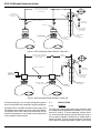
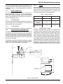
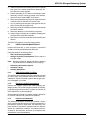
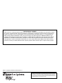
P/N 83-KRS100-001 September 2002 KRS-100 Nitrogen Releasing System Application, Operation and Maintenance Manual FM APPROVED UL Listing File No. EX 3559, EX 2153 KRS-100 Nitrogen Releasing System Table of Contents 1-1 Scope ........................................................................................................................................ 1 2-1 General Description ................................................................................................................... 1 3-1 3-1.1 3-1.1 3-1.1.1 3-1.1.2 3-1.2 3-1.3 3-1.3.1 3-1.4 Installation ................................................................................................................................. 2 Location ..................................................................................................................................... 2 POA & SVA Mounting ................................................................................................................ 3 POA Mounting ........................................................................................................................... 3 SVA Mounting ............................................................................................................................ 3 Actuator Valve Assembly Mounting ........................................................................................... 3 Tubing ........................................................................................................................................ 3 Tubing and Fittings .................................................................................................................... 3 Control Head Mounting (To Actuator Valve Assembly) .............................................................. 4 4-1 4-1.1 System Check-Out .................................................................................................................... 4 For Control Head Operation ...................................................................................................... 4 5-1 Readying the System ................................................................................................................. 4 6-1 6-1.1 6-1.2 6-1.3 Inspection And Maintenance ..................................................................................................... 5 KRS-100 Assembly Condition .................................................................................................... 5 Nitrogen Cylinder Pressurization ............................................................................................... 5 Detection and Actuation ............................................................................................................. 5 List of Figures 1 2 3 KRS-100 System Detail w/POA 87-100012-001 ........................................................................ 2 KRS-100 System Detail w/SVA 87-120042-001 ........................................................................ 2 Spacer Detail ............................................................................................................................. 3 List of Tables 1 September 2002 Tubing Limitations ..................................................................................................................... 3 83-KRS100-001 KRS-100 Nitrogen Releasing System THIS PAGE INTENTIONALLY LEFT BLANK. 83-KRS100-001 September 2002 KRS-100 Nitrogen Releasing System KRS-100 NITROGEN RELEASING SYSTEM Application, Operation, and Maintenance of KRS-100 Pneumatic Releasing Device 1-1 SCOPE sure-operated switches can be installed on the KRS-100 actuation line. This manual is to be used in conjunction with the UL Listed and Factory Mutual Approved Kidde Industrial Dry Chemical Instruction Manual (P/N 220423) dated November 1998, and the Kidde Wet Chemical Instruction Manual (P/N 87122000-001) dated February 1997. All other system limitations (control head, detection, manual pull, gas valve, etc.) must be in accordance with the respective instruction manuals. 2-1 Multiple KRS-100 releasing units may be used when the number of agent storage cylinders exceeds the maximum capacity of one KRS-100 releasing unit. The KRS-100 system is fully modular and is expandable to fit any size application. Two or more KRS-100 cylinders may be used when utilizing two or more different types of detection to cover the same hazard. An example would be the use of a combination of pneumatic rate-of-rise and fixed-temperature electric detection in a hazard. In this example a pneumatic rate of rise control head would be used on one KRS cylinder and an electric control head on the other. Operation of either detection system would release the extinguishing system by means of the KRS-100 releasing device to which it is connected. Refer to proper Kidde Instruction Manual listed in the scope of this addendum (Paragraph 1) for pneumatic detection, pneumatic control head, electric detection and electric control-head installation details. If using a Kidde control panel refer to the Installation Manual for the control panel for detection and control installation details. GENERAL DESCRIPTION The KRS-100 releasing device consists of a nitrogen cylinder (P/N 83-100004-001) and actuator valve assembly (P/ N 83-100010-001). The nitrogen cylinder is pressurized to 1800 psig (70°F). The function of the KRS-100 releasing device is to provide a pressure-operated means for releasing Kidde pre-engineered wet chemical and dry chemical fire-suppression systems. The KRS-100 utilizes the Kidde pre-engineered mechanical, pneumatic rate of rise, electric, and tandem control heads, any of which can be mounted on the KRS100 actuator valve assembly.The release is accomplished using KRS-100 cylinder pressure discharged through copper tubing into pressure-operated actuators (P/N 87100012-001 or 87-120042-001) located on Kidde pre-engineered wet or dry chemical system cylinders. (See Figure 1 and Figure 2.) Note: There are numerous applications where the use of the KRS100 simplifies the overall installation of an extinguishing system. It is often more convenient and economical to install the extinguishing system cylinders so that each is in close proximity to the space it protects rather than having all cylinders mounted together in a bank. Piping is thus kept to a minimum. Such an arrangement is conveniently implemented by the KRS-100. Pressure Operated Actuators (POA) P/N 87100012-001 and System Valve Actuators (SVA) P/ N 87-120042-001 cannot be mixed on any system. Use only one type on a system. Other applications include those where the hazard area is unsuitable for standard control heads. Here we can use the KRS-100 cylinder installed outside the unsuitable area with the actuation tubing run to the extinguishing system cylinders located within the area. When pressure from the KRS-100 cylinder is applied, the piston in the pressure-operated actuator pushes on the chemical cylinder valve stem. The piston remains in place (extended) until the pressure in the copper tubing is bled off and the pressure in each pressure-operated actuator is released. Pushing down on the valve core of the pressure-operated actuator releases this pressure. Note: The KRS-100 is ideally suited to a hazard consisting of kitchen range hoods on two or more floors, connected to a common exhaust duct. For this type of hazard each kitchen hood would be protected with an independent wet or dry chemical system. The detection for each hood, however, would be connected to a KRS-100 cylinder on its floor rather than to the wet or dry chemical system. Pressure in the pressure-operated actuator must be released before removing the actuator from the agent storage cylinder. (See Figure 1.) The KRS-100s on the various floors would be connected to each other and to each wet or dry chemical system. A fire at any hood would thus release all of the systems. In this way the entire hazard consisting of all the hoods and the common duct would be protected as required without the necessity of a complicated common detection system, In addition to the pressure-operated actuator, the KRS-100 can also be used to operate pressure-operated switches (P/Ns 486536 and 486536-010). A minimum of two and maximum of ten agent storage cylinders can be operated from one KRS-100. Up to 3 presSeptember 2002 1 83-KRS100-001 KRS-100 Nitrogen Releasing System 100 FT. MAX.- 1/4 INCH COPPER TUBING 50 FT. MAX. 1/4 INCH COPPER TUBING (3) THREE PRESSURE SWITCHES AND (10) TEN CYLINDERS VENT CHECK P/N WK-877810-000 (OPTIONAL) OUTLET APPROX. 2 1/2 INCHES IN DIA. MOUNTING KIT P/N 06-129706-001 VALVE CORE KRS-100 ACTUATOR VALVE ASSEMBLY P/N 83-100010-001 175 1207 175 OVE RCH ARG PSI 0 kPa 0 AL WET C EMIC LY ON 1207 OVE RCH ARG ED PSI 0 kPa 0 M WET OR DRY CHEMICAL SYSTEM CYLINDER US H WI TH ARGE 300 2069 300 2069 US E RECH ED 06-118031-001 E SST ELEMENT 06-118031-001 WI TH AL WET C EMIC LY ARGE SST ELEMENT ON H RECH M PRESSURE OPERATED ACTUATOR P/N 87-100012-001 KRS-100 (NITROGEN) CYLINDER P/N 83-100004-001 Figure 1. KRS-100 System Detail w/POA 87-100012-001 100 FT. MAX.- 1/4 INCH COPPER TUBING 50 FT. MAX. 1/4 INCH COPPER TUBING (3) THREE PRESSURE SWITCHES AND (10) TEN CYLINDERS OUTLET APPROX. 2 1/2 INCHES IN DIA. MOUNTING KIT P/N 06-129706-001 VENT CHECK P/N WK-877810-000 (OPTIONAL) OR ADDITIONAL CYLS. KRS-100 ACTUATOR VALVE ASSEMBLY P/N 83-100010-001 WET OR DRY CHEMICAL SYSTEM CYLINDER SYSTEM VALVE ACTUATOR P/N 87-120042-001 KRS-100 (NITROGEN) CYLINDER P/N 83-100004-001 Figure 2. KRS-100 System Detail w/SVA 87-120042-001 and without having to use a single extinguishing system which could be difficult to install within its piping limitations. Whenever two or more KRS cylinders are used, each must be isolated from the others by a check valve (P/N 259404). The purpose of the check valves is to prevent loss of pressure during discharge on one cylinder in the event that one of the cylinders is disconnected. 83-KRS100-001 3-1 INSTALLATION 3-1.1 Location The KRS-100 cylinder and actuator valve assembly shall be located where the temperature is between -40°F (-40°C) and 120°F (48.9°C). The entire assembly, cylinder, actuator, and control head must be protected from rain, snow, or other inclement weather conditions by a suitable total or partial enclosure. They all must be mounted in such a way that no part of the assembly stands in water or other liquid. 2 September 2002 KRS-100 Nitrogen Releasing System The KRS-100 releasing device may be mounted either vertically (plumb) with the control head or actuator at the top, or horizontally (level), or at any angle between vertical and horizontal. 3-1.1 3-1.3 Connect actuation tubing to the outlet on the KRS-100 actuator valve body. Ream and thoroughly clean all chips and cutting oil from the inside of tubing prior to connection. All tubing is to be securely supported, no more than ten feet on centers. (See Table 1 for tubing limitations.) POA & SVA Mounting Prior to mounting the actuator (POA P/N 87-100012-001 or SVA 87-120042-001) to the wet or dry chemical cylinder valve, make certain the actuator piston is flush with the bottom of the actuator body. If the piston is not flush, perform the following procedure. 3-1.1.1 Table 1. Tubing Limitations POA MOUNTING Place the unit on a flat surface and depress the valve core while pushing down on the assembly. This will push the piston into the body of the actuator. 3-1.1.2 Tubing SVA MOUNTING M ax. Min . To tal S ystem 150 ft. 5 ft. B etw een C o n tro l H ead an d F irst C ylin d er 50 ft. 3 ft. B etw een F irst an d L ast C ylin d er 100 ft. 2 ft. Push the spring loaded plunger in and push in the piston. 3-1.3.1 3-1.2 The KRS-100 system uses 1/4-inch O.D. copper tubing (0.030-inch minimum wall) with flared or high-compression tubing fittings. Tubing is also known as soft copper refrigeration/AC tubing. Flared fittings are SAE 45° flared brass tube. Compression fittings are high-pressure brass tube. Actuator Valve Assembly Mounting The actuator valve assembly (P/N 83-100010-001) can be mounted using the bolt holes located on the side flange of the actuator valve body. The total assembly should be secured to a surface which will support at least three times the total assembly dead weight. Use both mounting holes to secure the assembly. TUBING AND FITTINGS The copper tubing should be cut squarely with a tubing cutter and carefully reamed to remove all burrs before flaring with a standard flaring tool or applying compression fittings. The tubing need not be enclosed in conduit except where it would otherwise be exposed within seven feet of the floor, or where it is subject to cutting or crushing. There is no limit on bends, For applications where space is tight and clearance is needed between the control head and the wall, use a spacer (P/N 83100011-001) to provide the clearance. See Figure 3. #7 GA. 2.50 1.375 SAFETY PIN CAUTION REMOVE SAFETY PIN AFTER INSTALLING, INSPECTING OR SERVICING THE SYSTEM 0.312-18 UNC MOUNTING FLANGE 2.50 0.875 5.25 2.25 0.406 DIA. HOLE 0.375 CLEAR HOLE 0.625 3.50 SPACER P/N 83-100011-001 Figure 3. Spacer Detail September 2002 3 83-KRS100-001 KRS-100 Nitrogen Releasing System but bends must be made so that the tubing will not flatten or kink. A single coil of tubing approximately 2-1/2 inches in diameter is desirable at each flare or compression fitting. The coil may be neatly made by wrapping the tubing around any convenient cylindrical object of that diameter. 4-1 To demonstrate proper operation of the actuating system the following check-out is to be accomplished prior to installing the nitrogen cylinder (P/N 83-100004-001). 4-1.1 When sliding the tubing through conduit the leading end of the tube should first be crimped and bent double so as to provide a smooth sliding surface and to prevent possible foreign matter in the conduit from entering the tubing. All tubing fittings with pipe threads, as at the KRS-100 actuator valve body, the pressure-operated actuator and other accessory devices, shall be assembled with Teflon tape wrapped around the male pipe threads. Note: Control Head Mounting (To Actuator Valve Assembly) The system control head must be mounted to the KRS-100 actuator valve body using the mounting kit (P/N 06-129706-001) supplied with the Actuator Valve Assembly (P/N 83-100010-001). This kit contains a rubber gasket that must be placed between the mating surfaces of the actuator body and the control head housing. This kit also contains Teflon coated bolts and nylon washers for fastening the actuator valve assembly to the control head housing. Prior to mounting a control head on the KRS-100 actuator valve assembly make certain of the following: 1. The control head is in the SET position. On mechanical installations the manual release lever should be pushed up and the tensioning tool inserted in safety hole in the housing. On electrical installations make certain the solenoid trigger holds the actuating lever. The actuating cam arrow should be pointed away from the ratchet spool, (toward the SET position on faceplate), and the release plunger should be flush or slightly retracted within the control head body. 2. Ensure the safety pin is in place on the actuator valve assembly. See Figure 2. 3. Do not install the nitrogen cartridge at this time. Note: 5-1 Control Heads are shipped in the SET position with cover off for ease of installation. There are tensioning tools shipped with the mechanical and tandem control heads to enable proper tension setting on the cable. A tensioning tool may be used with the pneumatic control heads. There is no tensioning tool permitted with the electrical control heads. The plunger of the electric solenoid holds the control head mechanism in proper position for the SET position. 83-KRS100-001 For Control Head Operation 1. Remove the tensioning tool (when used) from the safety hole in the control head. If the system is properly installed, the head should remain in the SET position, fully prepared for either automatic or manual operation. 2. Remove safety pin from actuator valve assembly. 3. All cables, with the exception of remote pull cables, should be in a taut condition if properly installed. 4. For fusible link check-out, cut the S hook farthest from the control head (terminal link). The released tension should permit the control head to operate, triggering the releasing mechanism. 5. Check to see that the actuating cam is in the operated position and that the actuating cam (shaft arrow) has rotated to the released position. All cables should be slack, including remote cable. 6. To check out electrical control heads, do the following: Ensure that the actuating cam (shaft arrow) is turned to the SET position. Energize the control head by applying heat directly to the thermostats or operating the panel. 7. Check that the control head triggering mechanism has released. Check that the actuating cam arrow has rotated to the release position. 8. Check to see that the gas valve and/or electric shut-off have operated. Slack in the cable is an indication, but only the shut-off of gas and/or shut-off of electric current to the hazard demonstrates that these units have properly functioned. 9. Inspect all other aspects of system operation, such as dampers and door holders to see that the system has been installed properly. 10. After resetting the system as outlined below, repeat check-out by operating local and remote manual controls to assure their operation. All tubing should be blown out with air or nitrogen prior to making final connections. Table 1 summarizes the length of tubing allowed per each KRS-100 cylinder. 3-1.4 SYSTEM CHECK-OUT READYING THE SYSTEM If all conditions have proven to be operational, place system in operation as follows: 1. If the fusible link system is used, install a new S hook in the detection line. If the electric system is used, replacements should not be required. 2. Reset the control head. 3. Remove the control head tensioning tool when done, and discard. Electric control heads do not use tensioning tools. 4 September 2002 KRS-100 Nitrogen Releasing System 4. Install control head cover making sure notch in manual lever goes over manual release lever assembly. Secure with five screws supplied. 5. Ensure that safety pin is in place on the actuator valve assembly. If the pin cannot be placed in the actuator, verify that control head is SET. See Figure 2. 6. Remove and discard tensioning tools in gas valve and/ or electric shut-off and secure covers to units. 7. Turn on electric power and open main gas line shut-off valve. Ensure that pilot lights are lit. 8. Reset any electrical shutdown equipment operated by the switch contacts. 9. Reset any dampers or other auxiliary equipment. 10. Install nitrogen cartridge by completely threading the cartridge into the actuator assembly. 11. Remove the pin from the actuator valve assembly and discard. The KRS-100 system is now in the ready position. 6-1 INSPECTION AND MAINTENANCE Inspect semi-annually or more frequently. Inspections should be done by a qualified Kidde distributor. Particular attention should be given to: KRS-100 Assembly Condition. Nitrogen Cylinder Pressurization: Ensure that it is at proper weight. Note: Nitrogen cylinder full weight includes the shipping cap, ensure that it is installed prior to weighing. Detection and Actuation System. Actuation Tubing. Auxiliary Equipment. 6-1.1 KRS-100 Assembly Condition The actuator valve assembly must be inspected internally for nicks, dents, and scratches which would cause possible failure. Check to see that no part of the nitrogen cylinder is damaged or corroded. 6-1.2 Nitrogen Cylinder Pressurization Remove the nitrogen cylinder and install shipping cap. Weigh cylinder. Full cylinder weight is marked on the label. If cylinder weight loss exceeds 3.5 grams, the cylinder (P/ N 83-100004-001) must be replaced. When replacing a cylinder, the gasket located in the actuator (P/N WF-263413-000) must also be replaced. 6-1.3 Detection and Actuation The detectors should be checked (and cleaned if necessary) to assure that they are free of foreign substances. If the detection system is supervised, the supervisory features should be checked to determine that the detection system is in satisfactory condition. The methods and procedures for this inspection should be in accordance with manufacturers recommendations. September 2002 5 83-KRS100-001 KRS-100 Nitrogen Releasing System (THIS PAGE INTENTIONALLY LEFT BLANK) 83-KRS100-001 6 September 2002 LIMITED WARRANTY STATEMENT Kidde-Fenwal, Inc. represents that this product is free from defects in material and workmanship, and it will repair or replace any product or part thereof which proves to be defective in workmanship or material for a period of twelve (12) months from the date of purchase but not to exceed eighteen (18) months after shipment by Kidde-Fenwal Inc. For a full description of Kidde-Fenwals LIMITED WARRANTY, which, among other things, EXCLUDES warranties of MERCHANTABILITY and FITNESS FOR A PARTICULAR PURPOSE and liability for CONSEQUENTIAL DAMAGES, please read the entire LIMITED WARRANTY on the Kidde-Fenwal Quotation, Acceptance of Order and/or Original Invoice which will become part of your sales agreement. Please contact Kidde-Fenwal directly for a return material authorization (RMA) number before returning material to the factory at Ashland, Massachusetts, shipment prepaid. Kidde-Fenwal will repair or replace and ship prepaid. Kidde is a registered trademark of Kidde-Fenwal, Inc. These instructions do not purport to cover all the details or variations in the equipment described, nor do they provide for every possible contingency to be met in connection with installation, operation and maintenance. All specifications subject to change without notice. Should further information be desired or should particular problems arise which are not covered sufficiently for the purchasers purposes, the matter should be referred to KIDDE-FENWAL INC., Ashland, Masssachusetts 06-235864-001 Rev. AB ©2002 Kidde-Fenwal, Inc. Printed in USA