1
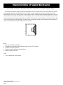
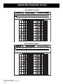
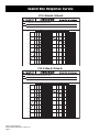
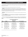
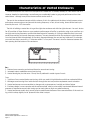
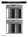
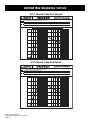
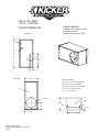
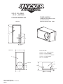
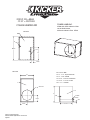
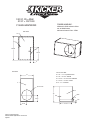
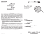
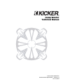
Comp Woofer Technical Manual Kicker Comp Subwoofers Recommended Applications / Version 2.0 June 13, 2002 Features y Hemispherical Polymineral Cone with Inverted Structural Dome™ (ISD) Means high rigidity under pressure for accurate linear control, low enclosure pressure loss to reduce "pump-down", high internal dampening, and excellent sunlight, pollution and moisture resistance y WARG (Wrap ARound Gasket) Instead of using cork gaskets, which can separate, the Comp Woofers have a one piece gasket that wraps around the front and back of the mounting flange. It is more durable and ergonomically pleasing to the eye. We learned from other previous models the cork gaskets could tear off or if you were transplanting the speaker into another box, they could stay adhered to the old box causing you to order a replacement. These problems are eliminated with the new rubber gaskets. They not only look better, but also function better by eliminating the chance for air leaks.(provided the box is built correctly!) We still recommend if you are carpeting the box, to cut away any carpet that is under the woofer mounting flange. y SSD (Spun Spoke Design) The basket not only looks impressive, but it is extremely functional. This stamped steel basket provides a solid foundation for the motor assembly insuring that all the parts work together in harmony and prevent shifting or misalignment. Without a solid foundation, the speaker’s various parts could shift under extreme excursion causing premature failure and add unwanted noise to the music. If misaligned, the voice coil could rub the inner wall of the motor structure and thus exposing the bare windings, which would cause speaker failure. The same thing happens if the coil former rubs the pole-piece. The damaged former exposes the windings causing speaker failure. When other speakers are pushed to their limits they tend to make noises that add coloration to the music. When you’re LIVIN’LOUD you only want here the music the artist intended you to hear, not a bunch of unwanted ringing. y Perimeter Venting Without the perimeter venting along the side of the speaker, hot air would be trapped in with the voice coil. This will cause the structure to heat up quicker and cause power compression, which results in decreased output, as well as shorter speaker life. Perimeter venting causes a vortex cooling effect around the coil which exchanges the hot air around the voice coil for cooler air outside the speaker. It also releases pressure from under the spider to allow the speaker to work in a more linear fashion. All of this translates into cooler operating temperatures which will allow the speaker to sound and perform better. with Vented Hyper-Extended Pole y Blackened One Piece Uniplate 1. Provides enhanced heat transfer for cool operation and maximum power handling. The heat is transferred from the pole piece to the back plate, effectively acting like a radiator in an engine. This lowers the operating temperature of the voice coil. Note:The increase in temperature increases the impedance of the speaker. This results in lower output and is referred to as Power Compression. 2. Reduces non-linear magnetic fields around the voice coil gap for superior cone motion control. The extended pole assures the voice coil is always in the magnetic field when moving peak to peak. When the speaker reaches it’s Xmax, the voice coil is still in the gap between the pole piece and magnet structure due to its extended pole-piece. 3. Releases pressure under ISD for freer cone motion and enhanced low frequency response. Air trapped under the ISD is forced out though the pole-piece to allow the cone to move freely. Heat and pressure build up under the ISD and need to be released to allow the speaker to function properly. Kicker Comp Subwoofers Recommended Applications / Version 2.0 Page 2 Features cont. y High-Temp Kapton® Voice Coil Former Heat is the primary enemy to the life of a speaker, which is one of the reasons we use Kapton® voice coil formers. Kapton® is a man-made product that is light, durable and heatresistant. The Kapton® former acts as an insulator to keep the heat of the voice coil from breaking down the adhesive that connects the voice coil to the cone. During high excursion and prolonged exposure to heat, the Kapton® former holds it’s shape and does not expand or contract. As a bonus, Kapton® is also a very quiet material during operation and does not discolor the music by adding unwanted sound ) Kicker was one of the first companies to switch to the Inverted Structural y ISD (Inverted Structural Dome Dome. We have designed a cone with a groove for the ISD to lock into, further adding strength to the structure. When a cone reaches it’s peak it wants to buckle because it’s momentum keeps it moving out. The ISD provides structural support for the cone to resist buckling. NOTE: When the cone buckles, the output of the woofer decreases. Therefore, the ISD is not just a cosmetic thing, it is an integral part of the woofer to maintain it’s maximum performance. y Stitched Surround A signature of KICKER woofers has always been the stitched surround. It prevents the surround from separating from the cone at high excursions. When the woofer is moving back and forth it puts a lot of strain on the adhesive that is holding the surround to the cone and often causes the two to separate. Stitching the surround to the cone eliminates this from happening. If stitching were inexpensive, everybody would do it! y Long-Throw Voice Coils A speaker can obtain extreme Xmax only when the voice coil is long enough and can sustain the stress. y High-Power Lead Wires Resist lead breakage and power robbing resistance losses under demanding conditions. When a speaker is being pushed to it’s limits there is a lot of strain being put on the leads. Sleeving tinsel leads help strengthen them to resist breakage. y Versatile Mounting Capabilities The Comp woofers have the unique capability of being mounted in a Sealed box, Ported box or on a Baffle mounted Free-air. This allows the Comp woofer to be one of the most popular speakers in the industry. Kicker Comp Subwoofers Recommended Applications / Version 2.0 Page 3 Kicker Comp Subwoofers Recommended Applications / Version 2.0 Page 4 One-Piece extended Pole, invented by Stillwater Designs, creates a broad, symmetrical magnetic field for superior power handling, precise voice coil control, and minimal deep bass distortion. Perimeter vents Create a vortex cooling effect around the voice coil. WARG (Wrap ARound Gasket) Provides greater durability and resistance to separation while providing a superior seal. Long-Throw Voice Coil on a Kapton Former For enormous cone excursion capabilities. High-Power Lead Wires To resist lead breakage and power-robbing resistance. Patented SSD (Spun Spoke Design) Enhances the cosmetics and provides a solid antiresonant foundation for the motor assembly. Signature Feature Stitched Surround It prevents the surround from separating from the cone at high excursions Vented pole piece Eliminates noise and distortion caused by huge amounts of airflow created by extreme cone excursion. ISD (Inverted Structural Dome) increases cone's resistance to flex under pressure. Hemispherical polymineral Cone with inverted Structural Dome(ISD) Means high rigidity under pressure for accurate linear control, high internal damping, UV, pollution, and moisture resistance. Comp Cutaway View Thank you for your support of KICKER products. Once you have had a chance to see and experience the capabilities of the new KICKER Comp subwoofers, we believe that you will be as excited as we are about these modestly priced masterpieces! The Comps truly set a new standard for bass performance in this category. This latest revision of our KICKER Comp Subwoofers Recommended Applications/Enclosures Technical Update brings together all of our Kicker Comp woofers into one manual. The enclosure recommendations in this paper supercede any other previously published recommendations. Especially when used in sealed enclosures, the new KICKER Comps will achieve maximum bass performance after they have been broken in. Approximately one to two weeks of daily playing will allow the suspension to soften, and reach its optimum equilibrium. This time period may vary depending on the amount of play time, volume level, and type of music you listen to. More play time, with medium volume levels and more bass content, will break in the subwoofer most quickly. The broken-in sub will exhibit stronger bass performance, smoother response, and greater low bass extension. For those of you with more sophisticated audio equipment, the Comp woofers can be broken-in on the test bench overnight with the following procedure. KICKER Comp Freeair Break-in Procedure 1. Connect the speaker to a power amp of about fifty watts or more. The speaker should not be mounted in any enclosure - just freeair. Please make sure it will not walk off the bench while it is playing! 2. Connect an audio generator to the input of the power amp, and adjust the generator to approximately 37Hz for the C8, 32 Hz for the C10, 28 Hz for the C12, and 17 Hz for the C15. 3. Now adjust the gain on the amplifier and generator so that the cone is moving to Xmax. This can be determined visually by looking at the “blur depth” of the logo on the ISD. A close approximation will do. On the C8 this will be about 3/4”, on the C10 about 3/4”, on the C12 about 7/8”, and on the C15 about 1”. NOTE: Keep in mind that as the speaker is used under normal conditions the break-in will continue, so if you don’t have time for the complete break-in period the speaker will still break-in itself under normal usage. Kicker Comp Subwoofers Recommended Applications / Version 2.0 Page 5 Sealed Enclosure Applications The KICKER Comp woofers are real performers in sealed enclosures, producing the tight, defined, and accurate bass response you would expect from a KICKER. They will operate in larger sealed enclosures for ultra sound quality (SQ) applications without significantly sacrificing their power handling. This extra bass extension and smoothness can be obtained by simply using a larger sealed enclosure. The box can be “sized up” all the way to the maximum SQ enclosure, which has a very flat response, with greatly extended sub bass. These sealed enclosure SQ recommendations will give the smoothest response with the most energy at really low frequencies, around 20 to 30 Hz. The recommended Compact sealed boxes are in line with our traditional Comp enclosures. They deliver massive amounts of high impact bass. And small size means they can fit just about anywhere. These versatile subwoofers are equally at home in a small Compact enclosure as they are in the larger SQ enclosures. As the sealed enclosure volume is increased, the response begins to shift from high impact bass to a smoother and more extended low bass response. Some of the impact is diminished, but the deep bass is actually enhanced. Model C8 C10 C12 C15 Recommended Enclosures - Moderate Efficiency Compact .50 cu.ft. Power Handling = 100W 14.16l 1.0 cu.ft. Power Handling = 125W 28.32 l 1.25 cu.ft. Power Handling = 150W 35.40 l 2.25 cu.ft. Power Handling = 250W 63.72 l SQ 1.2 cu.ft. Power Handling =100W 33.98l 2.4 cu.ft. Power Handling =125W 67.97l 3.5 cu.ft. Power Handling =150W 99.12 l 5.00 cu.ft. Power Handling = 250W 141.60l NOTE: All sealed boxes should be 50% filled with loose polyfil. Allow about two weeks break-in time for the Comp woofers to reach optimum low bass performance. Kicker Comp Subwoofers Recommended Applications / Version 2.0 Page 6 Characteristics of Sealed Enclosures The most basic and simple of all speaker enclosures is the sealed box or acoustic suspension design. The acoustic suspension design has several advantages; it is easy to build, easy to tune and offers high power handling, tight response and extended low end output. Acoustic suspension enclosures produce lower bass because they roll off at 12 dB per/octave. Cone motion is better controlled at all frequencies because of the constant pressure on the back side of the cone. This enables you to run more power to the woofer. They are called acoustic suspension enclosures because the air inside the box acts like a viscous brake to control the woofer. That is why the box needs to be sealed tight. If there are any air leaks the woofer cannot function properly because there is very little force being exerted back on the woofer. Pros 1 - High power handling capability 2 - Extended low frequency response and smooth roll off (12 dB/octave). 3 - Excellent transient response. 4 - Tolerant of minor enclosure size variations. 5 - Easiest enclosure to build. Cons 1 - Not as efficient as other designs. Kicker Comp Subwoofers Recommended Applications / Version 2.0 Page 7 Sealed Box Response Curves C8 .50cu.ft./1.2cu.ft. C C8 Compact Enclosure Response Curve C8 SQ Enclosure Response Curve 90 dB Graph 1 > Acoustic On Axis Response: SPL, Phase 85 80 75 70 65 60 55 C 50 10 Frequency 50 100 Hz 500 1K C10 1.0cu.ft./2.4cu.ft. C C10 Compact Enclosure Response Curve C10 SQ Enclosure Response Curve 90 dB Graph 1 > Acoustic On Axis Response: SPL, Phase 85 80 75 70 65 60 55 C 50 10 Kicker Comp Subwoofers Recommended Applications / Version 2.0 Page 8 Frequency 50 100 Hz 500 1K Sealed Box Response Curves C12 1.25cu.ft./3.5cu.ft. C C12 Compact Enclosure Response Curve C12 SQ Enclosure Response Curve 95 dB Graph 1 > Acoustic On Axis Response: SPL, Phase 90 85 80 75 70 65 60 C 55 10 Frequency 50 100 Hz 500 1K C15 2.25cu.ft./5.0cu.ft. C C15 Compact Enclosure Response Curve C15 SQ Enclosure Response Curve 95 dB Graph 1 > Acoustic On Axis Response: SPL, Phase 90 85 80 75 70 65 60 C 55 10 Kicker Comp Subwoofers Recommended Applications / Version 2.0 Page 9 Frequency 50 100 Hz 500 1K Ported/Vented Enclosure Applications Ported Comp drivers incorporate massive slot loaded ports with ultra low air velocity for ground pounding street bass that will make your hair stand on end (if you have any left)! These are the enclosures of choice for outrageous street bass and SPL contests. The following chart shows three recommended ported enclosures for each Comp driver. Compact has increased bass efficiency over a sealed enclosure, yet can still fit in tighter applications. It is the smallest design that will work well for each woofer. Although it is the smallest ported enclosure the output from 30 to 80 HZ will be considerably higher than that of a sealed box. This smallest vented design is for places where you can only give up the room normally taken up by two Comps in the normal small sealed boxes. The two other ported designs have proportionately more output in this region. Street Bass is a medium sized enclosure that will kick out bass that can be heard for blocks away. And it does go LOW! Finally, SPL / Deep Bass is a large enclosure that has it all. It is high efficiency and will deliver the output needed to win SPL contests, yet low frequencies go all the way down to the basement - with power that will shake the foundations! We’re talking truly awesome. If space is not at a premium and you want to get the most from your Comp driver, try one of these designs. You won’t be disappointed. Note: You must add the port volume to the volume of the box! See the cut sheets. Recommended Ported Enclosure – High Efficiency – Model C8 Compact .66 cu.ft. + port, 1.5x8" port, 18" long Power Handling = 55W Street Bass 1.0 cu.ft. + port; 1.5x8" port, 13.75" long Power Handling = 55W SPL / Deep Bass 1.2 cu.ft. + port; 1.5x8" port, 12.25" long Power Handling = 55W C10 1.25 cu.ft. + port; 1.5x10.5" port, 14.5" long Power Handling = 125W 1.5 cu.ft. + port 1.5x10.5", port 13.25" long Power Handling = 125W C12 1.75 cu.ft. + port; 2.0x12.5" port, 16" long Power Handling = 150W 2.0 cu.ft. + port; 2.0x12.5" port, 13.5" long Power Handling = 150W 2.25 cu.ft. + port; 2.0x12.5" port, 16.375" long Power Handling = 150W C15 3.0 cu.ft. + port; 2.75x15.5" port, 17" long Power Handling = 250W 3.5 cu.ft. + port; 3x15.5" port, 16.5" long Power Handling = 250W 4.0 cu.ft. + port; 3X15.5"port, 16.25"long Power Handling =250W NOTE: The use of a subsonic filter is necessary to insure the life of the woofer in a ported enclosure. Kicker Comp Subwoofers Recommended Applications / Version 2.0 Page 10 1.75 cu.ft. +port; 1.5x10.5" port, 13.25" long Power Handling = 125W Characteristics of Vented Enclosures A vented enclosure is not much more complex than a sealed box. It consists, basically, of a box with a hole in it. However, despite its simple design, vented boxes are considerably harder to get good performance from than sealed boxes - although many times the extra effort can be worth it. The vent in the enclosure interacts with the volume of air in the cabinet and the driver to help increase output and reduce cone excursion at and around the tuning frequency. In fact, at box tuning, almost all the bass is produced by the vent - NOT the woofer. The trick in building a vented box is to get the right size enclosure and with the right size vent. You can’t be too far off on either of these factors or your speaker’s performance will suffer. In particular, using a too-small box or a too-high vent tuning frequency can eliminate bass instead of increasing it. Porting a sealed box that is too small usually does nothing to improve frequency response. The vent placement within the enclosure is also important. You must leave at least the equivalent of the vent’s diameter between the vent and any inside wall. For example, you would not place a vent with a -3” diameter within 3” of any wall. The same is true for clearance between the vent opening and the bottom of the enclosure. Pros 1 - Reduced cone excursion and reduced distortion around vent tuning. 2 - Increased output capabilities around vent tuning. 3 - Vented boxes give you that extra “Bump” that is preferred in certain types of music. Cons 1 - Total loss of cone control below vent tuning, which can result in high distortion and driver mechanical failure. 2 - Midrange sound coming from inside the box through the vent can produce unpleasant sound coloration. 3 - Vented enclosures are more sensitive to changes such as temperature, humidity and driver fatigue. 4 - Enclosure design is more complex and the enclosure itself must be more solidly constructed because internal pressure at frequencies around vent tuning can be nearly twice as high as a sealed enclosure. 5 - Vented enclosures usually don’t sound as fast as sealed boxes because of the resonant effects of the vent tuning, which is always slightly out of phase with the driver’s output. Kicker Comp Subwoofers Recommended Applications / Version 2.0 Page 11 Vented Box Response Curves C8 .8cu.ft./1.0cu.ft./1.2cu.ft. C C8 Compact Enclosure Response Curve C8 Street Bass Response Curve C8 SPL/Deep Bass Enclosure Response Curve dB Graph 1 > Acoustic On Axis Response: SPL, Phase 90 85 80 75 70 65 60 C 55 10 Fr e que nc y 50 100 Hz 500 1K C10 1.25cu.ft./1.5cu.ft./1.75cu.ft. C C10 Compact Enclosure Response Curve C10 Street Bass Response Curve C10 SPL/Deep Bass Enclosure Response Curve 95 dB Graph 1 > Acoustic On Axis Response: SPL, Phase 90 85 80 75 70 65 60 C 55 10 Kicker Comp Subwoofers Recommended Applications / Version 2.0 Page 12 Frequency 50 100 Hz 500 1K Vented Box Response Curves C12 1.75cu.ft./2.0cu.ft./2.25cu.ft. C C12 Compact Enclosure Response Curve C12 Street Bass Response Curve C12 SPL/Deep Bass Enclosure Response Curve 100 dB Graph 1 > Acoustic On Axis Response: SPL, Phase 95 90 85 80 75 70 65 C 60 10 Frequency 50 100 Hz 500 1K C15 3.0cu.ft./3.5cu.ft./4.0cu.ft. C C15 Compact Enclosure Response Curve C15 Street Bass Response Curve C15 SPL/Deep Bass Enclosure Response Curve 100 dB Graph 1 > Acoustic On Axis Response: SPL, Phase 95 90 85 80 75 70 65 C 60 10 Kicker Comp Subwoofers Recommended Applications / Version 2.0 Page 13 Frequency 50 100 Hz 500 1K Box Building & Mounting Hints All the cubic feet numbers given in the supplied charts include the displacement of the woofer. For the ported boxes the displacement of the port must be added to the final design. It will be impractical to use round ports for these designs. The rectangular port information given will yield the best results. Always use 3/4” or thicker MDF and make sure all the joints are secure and well sealed. The peak pressure in a ported box can exceed that of a sealed enclosure. All of these designs need some internal bracing. Be sure to add 2”x2” to 3”x3” triangle braces between each of the larger unsupported panels. Kicker recommends using a good grade of wood glue and silicone X sealer for an airtight box. Note:If you prefer an ultra-smooth bass response, you should loosely fill your ported Comp Enclosure with polyfil. If you do so, the entrance to the port (inside the box) must be covered with hardware cloth, chicken wire, or expanded metal to prevent the polyfil from being blown out through the port. Use of polyfil will slightly decrease efficiency, but will deepen and extend low bass response. X X 50 % filled with Polyfil Chicken Wire or Expanded Metal Chicken Wire or Expanded Metal At Least 4 " Do not install a ported box with the port against a solid surface. The port opening must remain unobstructed. Use the smallest dimension of the rectangular port as the minimum amount of space required between the port and any surface to insure unrestricted airflow. Hatchback OR Trunk Kicker Comp Subwoofers Recommended Applications / Version 2.0 Page 14 Box Building & Mounting Hints If you would like to use a vented enclosure, but the box designs we provide you with (in this manual) do not fit because of width or depth the designs can be modified. The shape of the enclosure is not vital, but The Volume Is. The volume, of the design you choose, must stay the same. The following diagrams provide you with some help to insure your enclosure is built correctly. Front 45° Wedge Round Over Inner Corner Top Remember: If you are going to bend the port at 90° you will need to add 1/2 of the ports height to the length! See Below. Example: (Fig. 1) Hport = 3” Wport = 10” Lport = 20” Fig. 1 Fig. 2 3" 3" 10" 10" (Fig. 2) Since Hport is 3” you need to add 1.5”( 1/2 of Hport) to Lport. This means that L¹ + L² = 21.5” Always measure L¹ and L² down the center to get an accurate measurement! Kicker Comp Subwoofers Recommended Applications / Version 2.0 Page 15 L2 20" 3" L1 Box Building & Mounting Hints Here are a couple more examples of the different shape enclosures you can build. The woofer can be mounted on the same side as the port or the back side of the enclosure can be slanted to fit up against your back seat.. On the cut sheets we provide, change the dimensions to accommodate the woofer and the vent on the same side. Make sure the internal volume does not change! Top Side OR Top Kicker Comp Subwoofers Recommended Applications / Version 2.0 Page 16 Side Wiring Options The following diagrams are the most popular wiring configurations. They show a typical single channel wiring scheme. Check the amplifier’s owners manual for minimum impedance the amplifier will handle before hooking up the speakers. Remember: 4 Ohm mono is equivalent to 2 Ohm stereo. SINGLE WOOFER WIRING To + Amplifier Black - Red + WOOFERS WIRED IN PARALLEL WOOFERS WIRED IN PARALLEL 4 8 4 = 2 OHM Black - Black - Red + 8 = 4 OHM To + Amplifier To + Amplifier Red + Red + Red + WOOFERS WIRED IN SERIES WOOFERS WIRED IN SERIES 4 8 Black - 4 = 8 OHM Black - Black - + Red + Red + Kicker Comp Subwoofers Recommended Applications / Version 2.0 Page 17 8 = 16 OHM Black - + To Amplifier Red + Red + To Amplifier Wiring Options cont. WOOFERS WIRED IN PARALLEL Using 8 Ohm Woofers 8 8 Black - 8 = 2.66 OHM Black - Red + Black - To + Amplifier Red + Red + Using 4 Ohm Woofers 4 4 Black - Black - Red + 4 = 1.33 OHM Black - Red + To + Amplifier Red + WOOFERS WIRED IN PARALLEL Using 8 Ohm Woofers 8 Black - 8 8 Black - Red + 8 = 2 OHM Black - Red + Black - Red + To + Amplifier Red + Using 4 Ohm Woofers 4 Black - Red + Kicker Comp Subwoofers Recommended Applications / Version 2.0 Page 18 4 4 Black - 4 = 1 OHM Black - Red + Black - Red + To + Amplifier Red + .80 cf, Fb=44Hz .18 cf = Port Vol. POWER HANDLING: Comp8-BOX-VENTED-080 Side View B 55W with 25Hz Subsonic Filter set at 24db/Octave. Without subsonic filter 30W F E 21-3/4 18 D 1-1/2 Cut List: 3/4" MDF (2) 12 1/4" x 9 1/2" Top & Bottom(A) 9 1/2 (2) 12 1/4" x 20 1/4" Sides(B) (2) 8" x 20 1/4" Front & Back(C) Front View (1) 8" x 17 1/4" Port(D) (4) 2" x 2" Gusset(E) (1) 1 x 1 Corner Filet (F) C A ∅ 6-7/8 12-1/4 R 3/8 3/4 1-1/2 4-13/16 4-13/16 Kicker Comp Subwoofers Recommended Applications / Version 2.0 Page 19 3/4 8 1.00 cf, Fb=44Hz .14 cf = Port Vol. POWER HANDLING: Comp8-BOX-VENTED-100 55W with 25Hz Subsonic Filter set at 24db/Octave. Without subsonic filter 35W Side View B E 21-3/4 D 13-3/4 1-1/2 Cut List: 3/4" MDF (2) 13 3/4" x 9 1/2" Top & Bottom(A) 9 1/2 (2) 13 3/4" x 20 1/4" Sides(B) (2) 8" x 20 1/4" Front & Back(C) Front View (1) 8" x 13" Port(D) (4) 2" x 2" Gusset(E) C A ∅ 6-7/8 13-3/4 R 3/8 3/4 1-1/2 4-13/16 4-13/16 Kicker Comp Subwoofers Recommended Applications / Version 2.0 Page 20 3/4 8 1.20 cf, Fb=42Hz .12 cf = Port Vol. POWER HANDLING: Comp8-BOX-VENTED-120 55W with 25Hz Subsonic Filter set at 24db/Octave. Without subsonic filter 35W Side View B E 21-1/2 D 12-1/4 1-1/2 Cut List: 3/4" MDF (2) 15 3/4" x 9 1/2" Top & Bottom(A) 9 1/2 (2) 15 3/4" x 20" Sides(B) (2) 8" x 20" Front & Back(C) Front View (1) 8" x 11 1/2" Port(D) (4) 2" x 2" Gusset(E) C A ∅ 6-7/8 15-3/4 R 3/8 3/4 1-1/2 4-13/16 4-13/16 Kicker Comp Subwoofers Recommended Applications / Version 2.0 Page 21 3/4 8 1.25 cf, Fb=42Hz .19 cf = Port Vol. POWER HANDLING: C10-BOX-VENTED-125 125W with 25HZ Subsonic Filter set at 24db/Octave. Without subsonic filter 50W Side View B F D 24-1/4 14-1/2 1-1/2 12 Side View Cut List: 3/4" MDF (2) 11 3/4" x 12" Top & Bottom(A) (2) 11 3/4" x 22 3/4" Sides(B) (2) 10 1/2" x 22 3/4" Front & Back(C) C (1) 10 1/2" x 13 3/4" Port(D) (4) 2" x 2" Gusset(E) A ∅ -9-5/32 R3/8 11-3/4 6 6 Kicker Comp Subwoofers Recommended Applications / Version 2.0 Page 22 1-1/2 3/4 3/4 10-1/2 1.50 cf, Fb=42Hz .17 cf = Port Vol. POWER HANDLING: C10-BOX-VENTED-150 125W with 25HZ Subsonic Filter set at 24db/Octave. Without subsonic filter 50W Side View B F D 28-1/4 13-1/4 1-1/2 12 Side View Cut List: 3/4" MDF (2) 11 3/4" x 12" Top & Bottom(A) (2) 11 3/4" x 26 3/4" Sides(B) (2) 10 1/2" x 26 3/4" Front & Back(C) C (1) 10 1/2" x 12 1/2" Port(D) (4) 2" x 2" Gusset(E) A ∅ -9-5/32 R3/8 11-3/4 6 6 Kicker Comp Subwoofers Recommended Applications / Version 2.0 Page 23 1-1/2 3/4 3/4 10-1/2 1.75 cf, Fb=40Hz .15 cf = Port Vol. POWER HANDLING: C10-BOX-VENTED-175 125W with 25HZ Subsonic Filter set at 24db/Octave. Without subsonic filter 50W Side View B D F 29-1/4 13-1/4 1-1/2 12 Side View Cut List: 3/4" MDF (2) 12 3/4" x 12" Top & Bottom(A) (2) 12 3/4" x 27 3/4" Sides(B) (2) 10 1/2" x 27 3/4" Front & Back(C) C (1) 10 1/2" x 11" Port(D) (4) 2" x 2" Gusset(E) A ∅ -9-5/32 R3/8 12-3/4 6 6 Kicker Comp Subwoofers Recommended Applications / Version 2.0 Page 24 1-1/2 3/4 3/4 10-1/2 1.75 cf, Fb=40Hz .30 cf = Port Vol. POWER HANDLING: C12-BOX-VENTED-175 150W with 25HZ Subsonic Filter set at 24db/Octave. Without subsonic filter 75W Side View B F D 28 16 2 12 Side View Cut List: 3/4" MDF (2) 12 1/4" x 14" Top & Bottom(A) (2) 12 1/4" x 26 1/2" Sides(B) (2) 12 1/2" x 26 1/2" Front & Back(C) C (1) 12 1/2" x 15 1/4" Port(D) (4) 2" x 2" Gusset(E) A ∅ -10-7/8 R3/8 12-1/4 7 7 Kicker Comp Subwoofers Recommended Applications / Version 2.0 Page 25 2 3/4 3/4 12-1/2 2.00 cf, Fb=40Hz .30 cf = Port Vol. POWER HANDLING: C12-BOX-VENTED-200 150W with 25HZ Subsonic Filter set at 24db/Octave. Without subsonic filter 75W Side View B F 26 D 13-1/2 2 14 Side View Cut List: 3/4" MDF (2) 14 1/4" x 14" Top & Bottom(A) (2) 14 1/4" x 24 1/2" Sides(B) (2) 12 1/2" x 24 1/2" Front & Back(C) C (1) 12 1/2" x 12 3/4" Port(D) (4) 2" x 2" Gusset(E) A ∅ -10-7/8 R3/8 14-1/4 7 7 Kicker Comp Subwoofers Recommended Applications / Version 2.0 Page 26 2 3/4 3/4 12-1/2 2.25 cf, Fb=38Hz .31 cf = Port Vol. POWER HANDLING: C12-BOX-VENTED-225 150W with 25HZ Subsonic Filter set at 24db/Octave. Without subsonic filter 100W Side View B F 27-3/8 D 16-3/8 2 14 Side View Cut List: 3/4" MDF (2) 14 1/4" x 14" Top & Bottom(A) (2) 14 1/4" x 25 7/8" Sides(B) (2) 12 1/2" x 25 7/8" Front & Back(C) (1) 12 1/2" x 15 5/8" Port(D) C (4) 2" x 2" Gusset(E) A ∅ -10-7/8 R3/8 14-1/4 7 7 Kicker Comp Subwoofers Recommended Applications / Version 2.0 Page 27 2 3/4 3/4 12-1/2 3.00 cf, Fb=42Hz .51 cf = Port Vol. POWER HANDLING: C15-BOX-VENTED-300 250W with 25HZ Subsonic Filter set at 24db/Octave. Without subsonic filter 250W Side View B E 29-1/2 D 17 2-3/4 Side View Cut List: 3/4" MDF (2) 17" x 17" Top & Bottom(A) 17 (2) 17" x 28" Sides(B) (2) 15 1/2" x 28" Front & Back(C) (1) 15 1/2" x 16 1/4" Port(D) C (4) 2" x 2" Gusset(E) ∅ -13-11/16 A 17 R3/8 3/4 2-3/4 8-1/2 8-1/2 Kicker Comp Subwoofers Recommended Applications / Version 2.0 Page 28 3/4 15-1/2 3.50 cf, Fb=40Hz .53 cf = Port Vol. POWER HANDLING: C15-BOX-VENTED350 250W with 25HZ Subsonic Filter set at 24db/Octave. Without subsonic filter 250W Side View B E 28-3/4 D 16-1/2 3 Side View Cut List: 3/4" MDF (2) 18" x 17" Top & Bottom(A) 17 (2) 18" x 27 1/4" Sides(B) (2) 15 1/2" x 27 1/4" Front & Back(C) (1) 15 1/2" x 15 3/4" Port(D) C (4) 2" x 2" Gusset(E) ∅ -13-11/16 A 18 R3/8 3/4 3 8-1/2 8-1/2 Kicker Comp Subwoofers Recommended Applications / Version 2.0 Page 29 3/4 15-1/2 4.00 cf, Fb=38Hz .52 cf = Port Vol. POWER HANDLING: C15-BOX-VENTED400 250W with 25HZ Subsonic Filter set at 24db/Octave. Without subsonic filter 250W Side View B E 29-1/2 D 16-1/4 3 Side View Cut List: 3/4" MDF (2) 19 3/4" x 17" Top & Bottom(A) 17 (2) 19 3/4" x 28" Sides(B) (2) 15 1/2" x 28" Front & Back(C) (1) 15 1/2" x 15 1/2" Port(D) C (4) 2" x 2" Gusset(E) ∅ -13-11/16 A 19-3/4 R3/8 3/4 3 8-1/2 8-1/2 Kicker Comp Subwoofers Recommended Applications / Version 2.0 Page 30 3/4 15-1/2 Resistance Formulas 5 BASS BOOST (dB) 9 6 12 3 15 0 18 GAIN 0 11 X-OVER FREQ. (Hz) 50 200 5 BASS BOOST (dB) 9 6 12 3 15 0 18 GAIN 0 11 X-OVER FREQ. (Hz) 50 200 Kicker Comp Subwoofers Recommended Applications / Version 2.0 Page 31 Thiele/Small Parameters Model Nominal Impedance C158 8 C128 8 8 87.5 980 60.0 4-9/16 7.195 4.27 0.037 13.48 62.46 2.2 74.05 31.8 11.088 0.601 0.570 125 7.5 84.5 620.0 38.0 3-13/16 4.09 3.11 0.0206 9.08 21.99 0.75 49.55 36.8 10.179 0.578 0.547 100 7.5 88.8 3260 198.7 7-1/8 6.75 5.56 0.0856 20.39 301.46 10.64 234.42 18.7 12.745 0.462 0.446 250 13.0 88.5 1720 104.9 5-1/2 7.413 3.89 0.0532 14.9 127.53 4.5 100.17 27.3 12.167 0.593 0.565 150 7.5 Model C154 C124 SPL 1W/1M Displacement, cc Displacement, CuIn Mounting Depth Revc VC Inductance, mH Sd, SqM BL Vas, Liters Vas, CuFt Mms, gms Fs Qms Qes Qts Pmax, watts Xmax, mm 4 89.2 3260 198.7 7-1/8 3.30 3.25 0.0856 15.84 301.03 10.6 254.86 18.5 13.136 0.390 0.379 250 13.0 Kicker Comp Subwoofers Recommended Applications / Version 2.0 Page 32 C88 8 SPL 1W/1M Displacement, cc Displacement, CuIn Mounting Depth Revc VC Inductance, mH Sd, SqM BL Vas, Liters Vas, CuFt Mms, gms Fs Qms Qes Qts Pmax, watts Xmax, mm Nominal Impedance C108 C104 4 4 88.6 1718 104.89 5-1/2 3.79 2.83 0.0532 11.69 133.27 4.71 107.37 25.8 11.298 0.499 0.478 150 7.5 87.7 983 60.0 4-9/16 3.645 2.7 0.0370 10.17 59.48 2.10 75.808 32.2 10.534 0.555 0.527 125 7.5 C84 4 84.5 620.0 38.0 3-13/16 4.09 2.80 0.0206 9.08 21.99 0.75 49.55 36.8 10.179 0.578 0.547 100 7.5 Mounting Hole Cutouts 13-11/16 10-7/8 9-5/32 6-7/8 C8 C10 C12 C15 Kicker Comp Subwoofers Recommended Applications / Version 2.0 Page 33 Notes Kicker Comp Subwoofers Recommended Applications / Version 2.0 Page 34 SPEAKER SYSTEMS LIMITED WARRANTY Stillwater Designs warrants this product to be free from defects in material and workmanship under normal use for a period of one (1) year from date of original purchase from an Authorized Kicker Dealer, unless this product is labeled “B Stock”, in which case it is warranted for ninety (90) days from date of purchase. Should service be necessary under this warranty for any reason due to manufacturing defect or malfunction during the warranty period, Stillwater Designs will replace or repair (at its discretion) the defective merchandise with equivalent merchandise at no charge. Warranty replacements on “BStock” may have cosmetic scratches and blemishes. Discontinued products may be replaced with equivalent products. This warranty is valid only for the original purchaser and is not extended to owners of the product subsequent to the original purchaser. Any applicable implied warranties are limited in duration to a period of the express warranty as provided herein beginning with the date of the original purchase at retail, and no warranties, whether express or implied, shall apply to this product thereafter. Some states do not allow limitations on implied warranties, therefore these exclusions may not apply to you. This warranty gives you specific legal rights; however you may have other rights that vary from state to state. WHAT TO DO IF YOU NEED WARRANTY OR SERVICE Defective merchandise must be returned to your local Authorized Stillwater Designs (Kicker) Dealer for warranty. Assistance in locating an Authorized Dealer can be obtained by writing or calling Stillwater Designs direct. You can confirm that a dealer is authorized by asking to see a current authorized dealer window decal. If it becomes necessary for you to return defective merchandise, call the Kicker Customer Service Department at (405)6248510 for a Return Authorization (RA) number. Package all defective items in the original container or in a package that will prevent shipping damage, and return to Stillwater Designs, 5021 North Perkins Road, Stillwater, OK 74075 The RA number must be clearly marked on the outside of the package. Return only defective components. Return of entire cabinets, system packs, pairs, etc. increases your return freight charges. Non-defective items received will be returned freight collect. Include a dated proof-of-purchase from an Authorized Dealer. Warranty expiration on items returned without proof-ofpurchase will be determined from the manufacturing date code. Coverage may be invalidated if this date is greater than 18 months previous to the date item is sent in. Freight must be prepaid; items received freight collect will be refused. Failure to follow these steps may void your warranty. Any questions can be directed to the Kicker Customer Service Department at (405)624-8510. WHAT IS NOT COVERED? This warranty is valid only if the product is used for the purpose for which it was designed. It does not cover: • Items previously repaired by any • Install slips (screwdriver holes) unauthorized repair facility. • Damage caused by exposure to water • Items returned from unauthorized and/or excessive heat. individuals or dealers. • Damage through negligence, misuse, or • Return shipping on non-defective items. accident. • Speakers damaged due to amplifier • Items physically damaged due to abuse. clipping or distortion. • Freight damage. • Speakers with silicon caulk used for gasket • The cost of shipping product to Stillwater material. Designs Service. HOW LONG WILL IT TAKE? Stillwater Designs maintains a goal of 24-hour service for all returns. Delays may be incurred if lack of replacement inventory or parts is encountered. INTERNATIONAL WARRANTY Contact your International Stillwater Designs dealer or distributor concerning specific procedures for your country’s warranty policies. P.O. Box 459 • Stillwater, Oklahoma 74076 • U.S.A. • 405 624-8510 WARNING: KICKER drivers are capable of producing sound levels that can permanently damage your hearing! Turning up a system to a level that has audible distortion is more damaging to your ears than listening to an undistorted system at the same volume level. The threshold of pain is always an indicator that the sound level is too loud and may permanently damage your hearing. Pleaase use common sense when controlling volume!! June 2002 P.O. Box 459 x Stillwater, Oklahoma 74076 x U.S.A. x 405 624-8510 or www.Kicker.com