1
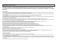
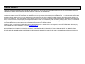
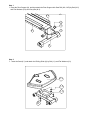
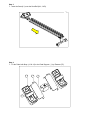
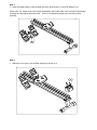
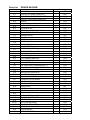
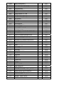
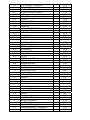
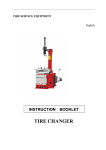
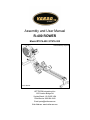
Assembly and User Manual
R-400 ROWER
Model #7976-400 / #7976-300
Adult Assembly Required
Picture Similar
KETTLER® International Inc
1355 London Bridge Rd.
Virginia Beach, VA 23453 USA
Parts/Service: 866.804.0440
Email: [email protected]
Web Address: www.kettlerusa.com
ASSEMBLY INSTRUCTIONS
Read these instructions carefully before assembling the product or using it for the first time. They contain important information for
your safety and for the correct use and maintenance of this product. Keep the instructions in a safe place for information or for ordering
spare parts.
For your safety
■ The unit should be used only for its intended purpose, i.e. for physical exercise by adult persons. Any other use of the equipment is prohibited and may be dangerous. The
manufacturer cannot be held liable for damage or injury caused by improper use of the equipment.
■ This unit has been designed in accordance with the latest standards of safety. Any features which may have been a possible cause of injury have been avoided or made as
safe as possible.
■ Incorrect repairs and structural modifications (e.g. removal or replacement of original parts) may endanger the safety of the user.
■ Damaged components may endanger your safety or reduce the lifetime of the equipment. For this reason, worn or damaged parts should be replaced immediately and the
equipment taken out of use until this has been done. Use only original KETTLER spare parts.
■ In case of inquiry, please contact KETTLER.
■ If the equipment is in regular use, check all its components thoroughly every 1 – 2 months. Pay particular attention to the tightness of bolts and nuts.
■ Before beginning your program of exercise, consult your doctor to ensure that you are fit enough to use the equipment. Base your program of exercise on the advice given by
your doctor. Incorrect or excessive exercise may damage your health!
■ Any interference with parts of the product that are not described within the manual may cause damage, or endanger the person using this machine.
■ Before use, always check all screws and plug-in connections as well as respective safety devices fit correctly.
■ Caution: While assembly of the product keep off children’s reach (Choking hazard - contains small parts).
■ Before beginning your first training session, familiarize yourself thoroughly with all the functions and settings of the unit.
■ Our products are subject to a constant innovative quality assurance. We reserve the right to perform technical modifications.
■ Attention! The unit should be positioned in such a way that there is a space of 100 cm (49 in) on both sides and 150 cm (59 in) behind it.
■ The unit requires a power supply. Before commissioning the appliance pay attention to the fact that the correct plug-in power supply unit (observe marking) has been
connected properly.
■ Important: disconnect the apparatus from the mains before doing repair, maintenance or cleaning work.
■ When the unit is not in use, unplug it from the power supply.
■ Ensure that the power cable is not pinched and that no one can trip over it.
■ All electric appliances emit electromagnetic radiation when in operation. Please do not leave radiation-intensive appliances (e.g. mobile telephones) directly next to the
cockpit or the electronic control system as otherwise values displayed might be distorted (e.g. pulse measurement).
■ Always observe the general safety rules and precautions for working with electrical equipment.
Handling the equipment
■ Before using the equipment for exercise, check carefully to en-sure that it has been correctly assembled.
■ It is not recommended to use or store the apparatus in a damp room as this may cause it to rust. Please ensure that no part of the machine comes in contact with liquids
(drinks, perspiration etc.). This may cause corrosion.
■ The machine is designed for use by adults and children should not be allowed to play with it. Children at play behave unpredictably and dangerous situations may occur for
which the manufacturer cannot be held liable. If, in spite of this, children are allowed to use the equipment, ensure that they are instructed in its proper use and supervised
accordingly.
■ Please ensure that liquids or perspiration never enter the machine or the electronics.
ASSEMBLY INSTRUCTIONS
Instructions for Assembly
■ Ensure that you have received all the parts required (see checklist) and that they are undamaged. Should you have any cause for complaint, please contact KETTLER.
■ Before assembling the equipment, study the drawings carefully and carry out the operations in the order shown by the diagrams.
■ Please note that there is always a danger of injury when working with tools or doing manual work. Therefore please be careful when assembling this machine.
■ Ensure that your working area is free of possible sources of danger, for example don’t leave any tools lying around. Always dispose packaging material in such a way that it
may not cause any danger. There is always a risk of suffocation if children play with plastic bags!
■ The equipment must be assembled with due care by an adult person.
■ The fastening material required for each assembly step is shown in the diagram. Use the fastening material exactly as instructed.
■ Bolt all the parts together loosely at first, and check that they have been assembled correctly. Then check that all screw connections have been tightened firmly.
■ Please keep original packaging of this article, so that it may be used for transport at a later date, if necessary.
Ordering Spare Parts
When ordering spare parts, always state the full model number, position, and the quantity required.
Example order: Model # 7979-400 / position A / 1 piece
Important: spare part prices do not include fastening material; if fastening material (bolts, nuts, washers etc.) is required, this should be clearly stated on the order by adding
the words „with fastening material“.
Goods may only be returned after prior arrangement and in (internal) packaging, which
is safe for transportation, in the original box if possible.
It is important to provide a detailed defect description / damage report!
Waste Disposal
VERSO by KETTLER products are recyclable. At the end of its useful life please dispose of this article correctly and safely (local refuse sites).
LIMITED WARRANTY
THERE ARE NO WARRANTIES, EXPRESSED OR IMPLIED, MADE BY EITHER THE DISTRIBUTOR OR THE MANUFACTURER ON KETTLER® PRODUCTS, EXCEPT
THE MANUFACTURER’S LIMITED WARRANTY AGAINST DEFECTS IN MATERIAL SET OUT BELOW:
This KETTLER® Limited Warranty applies to products sold through the KETTLER® Authorized Dealer Network to the original retail purchaser and authenticated by proof of
purchase from a retailer located in the United States. Any shipments made under this warranty will be shipped to the United States only. Any shipment outside of the United
States will be at the sole cost of the customer. This KETTLER® Limited Warranty is a manufacturer’s warranty and is not changed or modified by additional warranties
extended by individual retailers at the point of sale. Manufacturer warrants this product to be free from defects in material at the time of the product’s tender of delivery for a
period of 2 for residential use. This Limited Warranty is not transferable and does not cover normal wear and tear (including, but not limited to, damage and wear to tires, power
shocks, drive belts and other non-durable parts). The liability of the manufacturer under this Limited Warranty shall not include any liability for direct, indirect, or consequential
damages resulting from the defect. This Limited Warranty is void if the product is damaged by accident, unreasonable use, improper service, failure to follow instructions
provided, modification from its original state, or other causes determined not arising out of defects in material.
This warranty gives you specific legal rights. Should this product become defective due to material within the warranty period, contact KETTLER® Parts & Service Dept. by
phone at 866.804.0440, fax at 757.563.9273, or e-mail at [email protected].
THIS LIMITED WARRANTY IS EXPRESSLY IN LIEU OF ANY OTHER WARRANTIES, EXPRESSED OR IMPLIED, INCLUDING ANY IMPLIED WARRANTY OF
MERCHANTABILITY OR FITNESS FOR A PARTICULAR PURPOSE, AND OF ANY OTHER OBLIGATIONS OR LIABILITY ON THE PART OF THE MANUFACTURER.
KETTLER® NEITHER ASSUMES NOR AUTHORIZES ANY OTHER PERSON TO ASSUME FOR IT ANY OTHER LIABILITY IN CONNECTION WITH SUCH PRODUCTS.
CHECKLIST
R400
I-1 Allen Bolt M8x16mm
8
I-2 Curved washer for ? 8*? 19*2T bolt(8)
I-3 Screw M5*12 (8)
Screwdriver (1)
(Pedal Wrench)
Allen Key(1)
I-4 Screw M5*10 (4)
Assembly Instruction
D-16
D-15
D-13
D-14
K-1
I-2
D-35
I-1
D-13
D-14
D-37
J-3
I-3
J
O
J-5
I-1 I-2
I-4 N-6
Step 1
1. Insert the Rear Support (N), and then attach the Rear Support with Seat Rail (M-L, M-R) by Bolt (N-5)
and Flat Washers (N-4) and Carry Bar (N-3).
M-R
?
N-4
N-5
N-3
M-L
N
Step 2
1. Insert the Seat (K-1) and attach the Rolling Slider (K) by Bolt (I-1) and Flat Washers (I-2).
?
K-1
I-2
I-1
K
Step 3
1. Insert the Seat (K-1) onto the Seat Rail (M-L , M-R).
?
Step 4
1. Fix the Pedal with Strap (J-3 & J-5) to the Pedal Support ( J ) by Screws (I-3).
?
J-3
J-5
I-3
J
Step 5
1. Insert the Pedal Holder (J) into the Seat Rail (M-L, M-R) by Bolt (I-1) and Flat Washers (I-2).
Please note: The 4 bolts need to be loosely assembled to the Pedal Holder, ensure that the Pedal Holder
is straight and then tighten down the bolts. If this is not assembled properly, the seat will not slide
smoothly.
?
I-1 I-2
Step 6
1. Attach the Cover (N-6) over the Rear Support by Screws (I-4).
?
I-4 N-6
Step 7
1. Insert the Seat Rail (M-L, M-R), and attach the Main Frame (D) by Bolt (D-13) and Flat Washers (D-14).
2. Attach the Cover (D-15) over the Main frame (D) by Washers (D-16).
3. Connect the Cable (D-35, D-37).
4. Connect the Power Supply (O) onto the main frame to power on.
?
O
D-16
D-15
D-13
D-13
D-14
D-14
D-35
D-37
D-37
D-35
Explosion Drawing
F-10
F-9
F-8
F-7
F
F-1
F-4
G-4
G-3
G-2
G
G-10
L-1
F-3
L-6
A
D-17R
D-33
L
G-6 G-7 G-8 G-9
L-3
L-5
B-1
A-1
L-2
F-6
B
B-5 B-4 B-3 B-2
D-20R
F-2
F-5
G-5
G-1
D-34 D-35
L-4
D-36
D-23
C-7 C-8 C-1
C-9 C-3 C-4 C-10
D-22
E-7
D-30
D-12
C-6 C-5
D-11
D-32
C
D-29
D-27 D-26 D-25 D-24
C-2
D-28
D-16
D-15
D-10
D-7 D-8 D-9
E
D-13
D-14
E-5
E-4
E-3
E-2
E-1
K-1
E-6
I-2
D-20LD-21
D-1
D
I-1
I-4
D-2 D-14 D-13
D-37
H-20
K
H-19
H-18
D-19 D-17L D-18
D-4
H-17
H-16
H-15
J
D-6 D-5 D-3
H-14
H-13
J-1
J-2
J-3
K-2 K-3
M-R M-2 M-3
N-3 N-4 N-5 N-6
H-12
H-1
H-3
H
H-11
J-4
H-2
H-4
H-5
H-6
H-9
H-10
H-8
M-L M-1
H-7
D-31
O
J-5
I-3 I-1 I-2
N
N-1 N-2
Parts List
No.
A
A-1
B
B-1
B-2
B-3
B-4
B-5
B-6
C
C-1
C-2
C-3
C-4
C-5
C-6
C-7
C-8
C-9
C-10
C-11
C-12
D
D-1
D-2
D-3
D-4
D-5
D-6
D-7
D-8
D-9
D-10
D-11
D-12
D-13
D-14
D-15
D-16
D-17L
D-17R
D-18
D-19
D-20L
ROWER MACHINE
Description
Quantity
COMPUTER
SCREW FOR FIXING COMPUTER
1
4
SUPPORTING TUBE FOR BRACKET
BRACKET FOR FIXING COMPUTER
SCREW
FIXING CAP
FLAT WASHER φ6xφ16x1t
NYLON NUT M6
HEXAGONAL NUT M6xP1.0x57L
BRACKET FOR ROLLER
DRIVING PULLEY
ROLLER
SCREW
SCREW M6x50L
NYLON NUT 3/8"x7t
NYLON NUT M6
SCREW M8xP1.25x35L(6m/m)
FLAT WASHER φ8*φ19*2T
BUSHING φ10xφ14x6mmL
BUSHING φ6xφ8.5x3mmL
FLAT WASHER φ6xφ16x1t
FLAT WASHER φ10xφ18x1t
MAIN FRAME
CAP FOR FRONT STABLILZER(LEFT)
CAP FOR FRONT STABLILZER(RIGHT)
SUPPORTING CAP(LEFT)
SUPPORTING CAP(RIGHT)
ADJUSTING CAP
HEXAGONAL SCREW 3/8"-16x3t
TRANSPORTATION WHEEL
C-TYPE RING φ8
SPEEDY NUT M8
SENSOR BOX
SCREW M4x10L
GEAR BOX
SCREW M8*P1.25*16L(6m/m)
FLAT WASHER φ8*φ19*2T
FRONT CAP FOR SLIDER
SCREW M5x10L
LEFT COVER(LOWER)
RIGHT COVER(LOWER)
SCREW 3/16"(#10)x3/4"
1
1
2
4
2
2
1
1
SCREW M4x50L
SIDE COVER(LEFT)
1
1
1
1
1
1
2
2
2
4
1
1
1
1
1
1
1
2
2
2
2
2
2
2
1
8
8
1
8
1
1
2
3
1
SET
PCS
PCS
PCS
PCS
PCS
PCS
PCS
PCS
SET
SET
SET
PCS
PCS
PCS
PCS
PCS
PCS
PCS
PCS
PCS
PCS
SET
PCS
PCS
PCS
PCS
PCS
PCS
PCS
PCS
PCS
SET
PCS
PCS
PCS
PCS
PCS
PCS
PCS
PCS
PCS
PCS
PCS
D-20R
D-21
D-22
D-23
D-24
D-25
D-26
D-27
D-28
D-29
D-30
D-31
D-32
D-33
D-34
D-35
D-36
D-37
E
E-1
E-2
E-3
E-4
E-5
E-6
E-7
F~F-9
F
F-1
F-2
F-3
F-4
F-5
F-6
F-7
F-8
F-9
F-10
G~G-10
G
G-1
G-2
G-3
G-4
G-5
G-6
SIDE COVER(RIGHT)
SCREW M4x8L
CONNCTION PIN OF COVER
SCREW M4x12L
DIVERSION OF FAN
POLE
FIXING SOCKET OF FAN
SCREW M3x8
COVER OF FAN(FRONT)
FAN COVER
SCREW M5x8L
DC WIRE
SCREW M5x8L
CONNECTION BAR
CABLE UPPER
CONNECTION CABLE
CABLER LOWER
CONNECTION CABLE WITH RECEIVER
HANDLEBAR
PLASTIC WASHER φ45xφ32.2x0.5t
BUSHING φ32.2xφ44.3x29L
HEXAGON SCREW M6xP1.0x5L
BUSHING OF FOAM φ32.2xφ44.3x10L
HANDLEBAR FOAM
CAP
INKLE
FLYWHEEL SET
1
12
1
10
3
2
6
12
1
1
1
1
1
1
1
1
1
1
1
2
1
2
1
2
2
1
1
PCS
PCS
PCS
PCS
PCS
PCS
PCS
PCS
PCS
PCS
PCS
SET
PCS
PCS
PCS
PCS
PCS
PCS
SET
PCS
PCS
PCS
PCS
PCS
PCS
PCS
SET
FLYWHEEL
BEARING
FLYWHEEL AXLE
BEARING
BUSHING
NUT
NUT
FIXING PIN
FAN
SCREW
1
1
1
1
1
3
2
1
1
4
PCS
PCS
PCS
PCS
PCS
PCS
PCS
PCS
PCS
PCS
DRIVING BELT
IDER WHEEL SET
1
1
PCS
SET
IDER WHEEL
CURVED WASHERφ10.5xφ15x0.3t
IDLER WHEEL WITH BEARING
BEARING #6000RS
FLAT WASHERφ6xφ16x1t
SCREW M6xP1.0x12L
SCREW M8xP1.25x20L
1
1
1
2
1
1
1
SET
PCS
PCS
PCS
PCS
PCS
PCS
G-7
G-8
G-9
G-10
H~H-20
H
H-1
H-2
H-3
H-4
H-5
H-6
H-7
H-8
H-9
H-10
H-11
H-12
H-13
H-14
H-15
H-16
H-17
H-18
H-19
H-20
I-1
I-2
I-3
I-4
J
J-1
J-2
J-3
J-4
J-5
K
K-1
K-2
K-3
L~L-6
L
L-1
L-2
L-3
L-4
FLAT WASHERφ8.5xφ25x1t
FLAT WASHERφ8xφ16x1t
NYLON NUT M8
SPRING FOR IDLER WHEEL
1
1
1
1
PCS
PCS
PCS
PCS
SPRING BOX
1
SET
SPRING BOX
SPRING
FLYWHEEL AXLE
SCREW M4x5L
FIXING PIN
COVER OF SPRING BOX
SCREW M4*12L
BUSHING φ10xφ14x3mmL
NUT 3/8"-26x4.5t
FIXING PIN
NUT
BEARING # 6000RS
IRON RING(1)
SCREW M5xP0.8x12L
IRON RING(2)
BEARNG #6203
ONE WAY BEARING
PULLEY
BEARING #6003RS
FLAT WASHERφ30xφ34x1t
BEARING #6300RS
1
1
1
1
1
1
4
1
3
1
2
1
1
2
1
1
1
1
1
1
1
PCS
PCS
PCS
PCS
PCS
PCS
PCS
PCS
PCS
PCS
PCS
PCS
PCS
PCS
PCS
PCS
SET
PCS
PCS
PCS
PCS
SCREW M8*P1.25*16L(6m/m)
FLAT WASHER φ8*φ19*2T
SCREW M5xP0.8x12L
SCREW M5*P0.8*10L
PEDAL HOLDER
STOPPER
SCREW M5x25L
PEDAL
PAD OF PEDAL
PEDAL STRAP
ROLLING SLIDER
SEAT
ROLLER
NLYON NUT M8
MAGNETIC SET
8
8
8
4
1
1
2
2
2
2
1
1
4
4
1
PCS
PCS
PCS
PCS
SET
PCS
PCS
PCS
PCS
PCS
SET
PCS
SET
SET
SET
MAGNETIC BRACKET
NYLON NUT M6
FLAT WASHERφ6xφ13x1t
CURVED WASHERφ12.5xφ18x0.3t
AXLE FORMAGNETIC SOCKET
1
2
2
1
1
PCS
PCS
PCS
PCS
PCS
L-5
L-6
M-L
M-R
M-1
M-2
M-3
C-TYPE RING
SCREW M6
2
2
PCS
PCS
LEFT SEAT RAIL
RIGHT SEAT RAIL
SCREW M5x30L
NYLON NUT M5
STOPPER FOR SILDER
1
1
2
2
1
N
N-1
N-2
N-3
N-4
N-5
N-6
O
REAR STABILIZER
ADJUSTING CAP
SCREW 3/16"(#10)x3/4"
1
2
2
1
4
4
1
1
PCS
PCS
PCS
PCS
PCS
SET
PCS
PCS
PCS
PCS
PCS
PCS
SET
CARRY BAR FOR TRANSPORTATION
FLAT WASHER φ8xφ16x2t
SCREW M8xP1.25x20L(6m/m)
REAR COVER FOR SLIDER
POWER SUPPLY
INSTRUCTION MANUAL OF SM5880
【FUNCTION BUTTONS】
UP / DOWN:
To press these two buttons through available selection.
To adjust the function value upward and downward.
ENTER:
To confirm your selection.
During training, press the button to scan each display function.
START / STOP: To start and stop your selected workout program.
RESET:
To reset the computer back to the main menu.
RECOVERY:
To activate the RECOVERY PROGRAM that will automatically evaluate your fitness immediately
after your work out.
【FUNCTIONS】
TIME:
TIME/500M:
DISTANCE:
CALORIES:
STROKES:
Preset target time by pressing UP and DOWN buttons (1min ~ 99 min), each increase/ decrease
setting is 1 minute.
Computer will display the time needed to row 500 meters according to current speed.
Preset target value by pressing UP and DOWN buttons ( 10meters ~ 9990meters), each
increase / decrease setting is 100 meters.
Preset target value by pressing UP and DOWN buttons (0~9999 strokes). each increase /
decrease setting is 10.
TOTAL STROKES: Accumulates total strokes from 0 up to 9999.
PULSE:
To preset target value by pressing up/down/mode from 30 to 240, each increase/decrease setting
is 1. The monitor will display user’s heart rate during training. The pulse measurement function
is only used by chest belt system; the frequency of chest belt accepted by the monitor is 5 KHz.
RECOVERY:
After exercising for a period of time, keep holding on handgrips and press “RECOVERY”
button. All function display will stop except “TIME” starts counting down from 00:60 to 00:00.
Screen will display your heart rate recovery status with the F1,F2….to F6. F1 is the best, F6 is
the worst. User may keep exercising to improve the heart rate recovery status. (Press the
RECOVERY button again to return the main display.)
CALENDAR:
The monitor will display year, month, and day when monitor is in sleep mode.
TEMPERATURE: The monitor will display current room temperature from 0° to 60° C when the monitor is in sleep
mode.
CLOCK:
The monitor will display current clock when the monitor is in sleep mode.
【OPERATION】
1. Power on
Plug in the power supply, the monitor starts to segment test with a long beep sound, then monitor will enter into
calendar/clock setting mode.
2. Set current data
Press UP/DOWN/ENTER buttons to set up current clock time, year, month and day. After you confirm it, the ALARM
will blink, press UP or DOWN to set the ON/OFF which is the sign of ALARM. If the sign doesn’t display on LCD,
you can press ENTER key to jump to the standby mode. If the sign of ALARM display on LCD, you can press
ENTER key to set the time of ALARM (to set the clock in same way). Enter into the initial (standby) mode after
confirmed.
Note : All preset data will be updated automatically after first setting till power off (power supply plug-out).
3. Entered the initial (standby) mode, the STOP/MANUAL/PROGRAM/H.R.C./RACE/USER will blink to be
selected, press UP/DOWN for function selection and ENTER for confirmation.
3-1. MANUAL
A. Enter into this function, “L1” will blink on the monitor for resistance setting, you can preset the target
resistance from L1 to L16 by pressing UP/DOWN/ENTER button. After confirmed, you can preset target
value for TIME, DISTANCE, STROKES, CALORIES, PULSE in the same way.
Note : As Time is set, the DISTANCE can’t be set, if you set the target time you wish to exercise, each
segment would contain the time length of target value divided by 16.
As DISTANCE has been set, the TIME can’t be set, if you set the target distance you wish to
exercise, each segment would contain the distance length of target value divided by 16.
If you didn’t set the value of TIME or DISTANCE, each segment would contain the distance length
of 100M.
B. Press START button to start exercise, the STOP sign will disappear. All values start counting up or down.
Press UP or DOWN button to adjust the resistance as you want and its figure will display on the matrix
(level 1 ~ level 16).
C. When the any target value of you set count down to zero or you have pressed the STOP button, the
monitor will stop and display the average figure of TIME/500M.
3-2. PROGRAM
User can select the program profile from P1 to P12 by pressing UP/DOWN/ENTER button, after selected, user
can preset the exercise level from L1 to L16 by pressing UP/DOWN/ENTER button, also can adjust the level
during exercising.
A. Enter into this function, press UP/DOWN to set the target profile from P1 to P12, and press ENTER for
confirmation. Then “L1” will blink on the monitor, you can press UP/DOWN/ENTER button to set target
exercise level from L1 to L16. After level confirmed, you can preset the target value for TIME, DISTANCE,
STROKES, CALORIES, PULSE in the same way.
Note : As Time is set, the DISTANCE can’t be set, if you set the target time you wish to exercise, each
segment would contain the time length of target value divided by 16.
As DISTANCE has been set, the TIME can’t be set, if you set the target distance you wish to
exercise, each segment would contain the distance length of target value divided by 16.
If you didn’t set the value of TIME or DISTANCE, each segment would contain the distance length of
100M.
B. Press START button to start exercise, the STOP sign will disappear. All values start counting up or down.
Press UP or DOWN button to adjust the resistance as you want and its figure will display on the matrix
(level 1 ~ level 16). During exercising, the value of TIME and TIME/500M will be scanned in 6 seconds
automatically.
C. When the any target value of you set count down to zero or you have pressed the STOP button, the monitor will
stop and display the average figure of TIME/500M and SPM.
3-3. H.R.C.
You can preset the target percentage for heart rate control in this function.
A. Enter into this function, the monitor will blink with “AGE 25”, press UP/DOWN/ENTER to set your age in
advance, after confirm, you can select the percentage of heart rate 55%, 75%, 90%, and TAG which be
displayed in pulse area by pressing UP/DOWN/ENTER button for target heart rate setting. If the
percentage of heart rate doesn’t meet your demand, you can also preset your demanded heart rate value
by pressing UP/DOWN/ENTER button after TAG selected. After target heart rate confirmed, you may
preset the target value for TIME, DISTANCE, STROKES, CALORIES, and PULSE in the same way.
Note : As Time is set, the DISTANCE can’t be set, if you set the target time you wish to exercise, each
segment would contain the time length of target value divided by 16. As DISTANCE has been set,
the TIME can’t be set, if you set the target distance you wish to exercise, each segment would
contain the distance length of target value divided by 16. If you didn’t set the value of TIME or
DISTANCE, each segment would contain the distance length of 100M.
B. Press START button to start exercise, the STOP sign will disappear. All values start counting up or
down. During exercising, the value of TIME and TIME/500M, STROKES and TOTAL STROKES,
CALORIES will be switched in each 6 seconds automatically. You may also press “ENTER” to
show TIME, SPM, DISTANCE, STROKES, and CALORIES in the main screen (middle).
C. When the any target value of you set count down to zero (the computer will remind you with beep sound)
or you have pressed the STOP button, the monitor will stop and display your current heart rate.
Note : The computer will keep following your heart rate value and adjust the resistance automatically
during exercising, when your heart rate is lower than target value, the resistance will be increased
one level up (L1, L2, L3…) by computer in each 30 seconds automatically till L16.
When your heart rate reached target value, the resistance will be decreased one level down
immediately, if your heart rate keep over target value, the resistance will be decreased one level
down (L16, L15, L14,..) by computer automatically in each 15 seconds.
When your heart rate is over target value and resistance has downed to lowest (L1) or your heart
rate keep lower than target value and resistance has reached highest (L16), the computer will
remind you with beep sound.
When your heart rate keep higher than target value over 30 seconds at lowest resistance (L1), they
computer will STOP automatically, it’s protection system for heart rate control.
3-4. RACE
A. Entered into the RACE and L1 will blink, the TIME/500M display with 8:00. You can press UP or DOWN to
set difficult of L1 ~ L15 which you want to race with monitor immediately, then press ENTER to confirm.
Then you can set the target race distance by pressing UP/DOWN/MODE button.
The difficult of L1 ~ L5 figure of the TIME/500M is as follows:
L1 = 8:00 ; L2 = 7:30 ; L3 = 7:00 ; L4 = 6:30 ; L5 = 6:00
L6 = 5:30 ; L7 = 5:00 ; L8 = 4:30 ; L9 = 4:00 ; L10 = 3:30
L11 = 3:00 ; L12 = 2:30 ; L13 = 2:00 ; L14 = 1:30 ; L15 = 1:00
B. Press START button to start race and STOP sign will disappear. The U & PC will display in the matrix. The
monitor will STOP when one has reached the distance of race which has been set before, then the matrix
displays “PC WIN” or “USER WIN” and may display figure for the status of the SPM value during all
exercise after 6 seconds.
C. When the race is over, you can press the START to have a race once again, press reset to leave the state
of the race.
3-5. USER
Entered into this function, you may set the favor program profile for training, press UP/DOWN/MODE button to
set up exercising graph you wish.
A. After confirmed user function, you can see the first column blink on the monitor, and press
UP/DOWN/MODE to set the level from 1 to 16, the each grid increase/decrease is 2 levels. Hold the
ENTER for 2 seconds to enter into initial (standby) mode, then you can preset target value for TIME,
DISTANCE, STROKES, CALORIES, PULSE for setting.
B. Press START button to start exercise, the STOP sign will disappear. All values start counting up or down.
You can press UP or DOWN button to adjust the resistance for each blinking program profile as your wish
(all profiles will blink in sequence automatically). During exercising, the value of TIME and TIME/500M,
STROKES and TOTAL STROKES and CALORIES will be switched in each 6 seconds automatically. You
may also press “ENTER” to show TIME, SPM, DISTANCE, STROKES, and CALORIES in the main
screen (middle).
C. Press STOP button to stop the exercise, the monitor will stop and display your current heart rate on the
main screen (middle) and TIME and TIME/500M will blink in turn each 6 seconds.