1
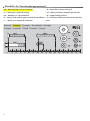
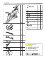
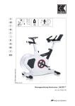
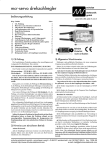
Montageanleitung „RACE“
Art.-Nr. 07938-180
deutsch
english
française
nederlands
español
italiano
polski
čeština
dansk
português
Abb. ähnlich
B
C
A
A
B
C
120 cm
53 cm
120 cm
56 kg
max.
130 kg
45 – 55 Min.
english
Assembly Instr uctions
Before assembling or using the exercise cycle , please read the following instructions carefully. They contain important
information for use and maintenance of the equipment as well as for your personal safety. Keep these instructions in a
safe place for maintenance purposes or for ordering spare parts.
For Your Safety
!
RISK! Instruct people using the equipment (in particular children)
of use until this has been done. Use only original KETTLER
spare parts.
on possible sources of danger during exercising.
!
RISK! While assembly of the product keep off children’s reach
(Choking hazard - contains small parts).
!
RISK! Heart rate monitoring systems can be imprecise. Excessive
training may lead to serious health damage or death. If you feel
giddy or weak, please stop the training immediately.
!
If the equipment is in regular use, check all its components
thoroughly every 1 -2 months. Pay particular attention to the
tightness of bolts and nuts.This applies especially to the securing
bolts for saddle and handelbars.
■
To ensure that the safety level is kept to the highest possible
standard, determined by its construction, this product should
be serviced regulary (once a year) by specialist retailers.
WARNING! The training device should be used only for its
intended purpose, i.e. for physical exercise by adult people.
!
■
WARNING! Any other use of the equipment is prohibited and
■
Before beginning your program of exercise, consult your doctor
to ensure that you are fit enough to use the equipment. Base your
program of exercise on the advice given by your doctor. Incorrect
or excessive exercise may damage your health!
■
Any interference with parts of the product that are not described
within the manual may cause damage, or endanger the person
using this machine. Extensive repairs must only be carried out
by KETTLER service staff or qualified personnel trained by
KETTLER.
■
Our products are subject to a constant innovative quality assurance.
We reserve the right to perform technical modifications.
■
In case of enquiry, please contact your KETTLER dealer.
■
In choosing the location of the apparatus, ensure a sufficient safety
distance from any obstacles. The apparatus must not be mounted
in the immediate vicinity of main passageways (paths, doorways,
corridors).
■
For a comfortable training position please adjust the handlebar
andsaddle position to your body height.
■
When mounting the product please take the recommended
torque information into account (M = xx Nm).
■
The exercise cycle complies with the DIN EN 957 - 1/5, class
HC. It is therefore unsuitable for therapeutic use.
■
The machine is designed for use by adults and children should
not be allowed to play with it. Children at play behave unpredictably and dangerous situations may occur for which the manufacturer cannot be held liable. If, in spite of this, children are
allowed to use the equipment, ensure that they are instructed
in its proper use and supervised accordingly.
A slight production of noise at the bearing of the centrifugal mass
is due to the construction and has no negative effect upon operation. Possibly occurring noise during reverse pedalling result
from engineering and are absolutely safe.
may be dangerous. The manufacturer cannot be held liable for
damage or injury caused by improper use of the equipment.
!
WARNING! Before beginning your program of training, study
the instructions for training carefully.
!
!
WARNING! All electric appliances emit electromagnetic
radiation when in operation. Please do not leave especially
radiation-intensive appliances (e.g. mobile telephones) directly
next to the cockpit or the electronic controlsystem as otherwise
values displayed might be distorted (e.g. pulse measurement.
WARNING! After your training by all means turn the turning
handle for brake adjustment back to zero position in order to
avoid heat influences on brake linings and disk flywheel.Pay
attention to the fact that the quickly rotating disk flywheel
strongly heats during operation.
■
Exercise has been designed in accordance with the latest standards of safety. Any features which may have been a possible
cause of injury have been avoided or made as safe as possible.
■
Incorrect repairs and structural modifications (e.g. removal or
replacement of original parts) may endanger the safety of the
user.
■
Damaged components may endanger your safety or reduce the
lifetime of the equipment. For this reason, worn or damaged parts
should be replaced immediately and the equipment taken out
Handling the equipment
!
ATTENTION! It is not recommended to use or store the apparatus in a damp room as this may cause it to rust. The friction
surface of the flywheel is especially sensitive to the formation
of rust. Should this occur (e.g. after a prolonged period of disuse)
the rust should be removed using sandpaper or steel wool. Do
not use grease or oil! Please ensure that no part of the machine
comes in contact with liquids (drinks, perspiration etc.). This may
cause corrosion.
■
Before using the equipment for exercise, check carefully to
ensure that it has been correctly assembled.
■
Before beginning your first training session, familiarize
yourself thoroughly with all the functions and settings of the
unit.
4
■
■
Use for your regular cleaning, maintenance and care our
appliance maintenance set (Article no. 07921-000) specifically licensed for KETTLER Sports apparatus and available from
english
Always wear suitable shoes when using.
the Sport specialized trade.
■
■
To operate correctly, the pulse function requires a minimum
■
Nobody may be in the moving range of a training person during
training.
■
The equipment is dependent of revolutions per minute.
■
■
Please ensure that liquids or perspiration never enter the machine
or the electronics.
After your training by all means turn the turning handle for brake
adjustment back to zero position in order to avoid heat influences
on brake linings and disk flywheel.
■
Before use, always check all screws and plug-in connections as
well as respective safety devices fit correctly.
■
The brake linings should also be checked at regular intervals
and adjusted as necessary.
■
The fastening material required for each assembly step is shown
in the diagram inset. Use the fastening material exactly as
instructed.
■
Bolt all the parts together loosely at first, and check that they
have been assembled correctly. Tighten the locknuts by hand
until resistance is felt, then use spanner to finally tighten nuts
completely against resistance (locking device). Then check that
all screw connections have been tightened firmly. Attention:
once locknuts have been unscrewed they no longer function correctly (the locking device is destroyed), and must be replaced.
■
For technical reasons, we reserve the right to carry out preliminary assembly work (e.g. addition of tubing plugs).
voltage of 2,7 volts (only for computers working with batteries).
Instr uctions for Assembly
!
RISK! Ensure that your working area is free of possible sources
of danger, for example don’t leave any tools lying around. Always
dispose packaging material in such a way that it may not
cause any danger. There is always a risk of suffocation if
children play with plastic bags!
■
Ensure that you have received all the parts required (see check
list) and that they are undamaged. Should you have any cause
for complaint, please contact your KETTLER dealer.
■
Before assembling the equipment, study the drawings carefully
and carry out the operations in the order shown by the diagrams.
The correct sequence is given in capital letters.
■
The equipment must be assembled with due care by an adult
person. If in doubt call upon the help of a second person, if possible technically talented.
■
Please note that there is always a danger of injury when
working with tools or doing manual work. Therefore please be
careful when assembling this machine.
List of spare par ts page 33-35
When ordering spare parts, always state the full article number,
spare-partnumber, the quantity required and the S/N of the product
(see handling).
Waste Disposal
KETTLER products are recyclable. At the end of its useful life please
dispose of this article correctly and safely (local refuse sites).
Example order: Art.no. 07938-180 / spare-part no. 10100030
/ 2 pieces / S/N ....................
Please keep original packaging of this article, so that it may be
used for transport at a later date, if necessary.
Goods may only be returned after prior arrangement and in
(internal) packaging, which is safe for transportation, in the original
box if possible.
It is important to provide a detailed defect description / damage
report!
Important: spare part prices do not include fastening material; if
fastening material (bolts, nuts, washers etc.) is required, this should
be clearly stated on the order by adding the words „with fastening
material“.
Heinz KETTLER GmbH & Co. KG
SERVICECENTER
Henry-Everling-Str. 2
+49 (0)2307 974-2111
D-59174 Kamen
+49 (0)2307 974-2295
www.kettler.de
Mail: [email protected]
D
KETTLER Austria GmbH
Ginzkeyplatz 10
5020 Salzburg
www.kettler.at
A
Trisport AG
Im Bösch 67
CH - 6331 Hünenberg
Servicehotline Schweiz:
www.kettler.ch
+43 662 620501 0
+43 662 620501 20
Mail: [email protected]
CH
0900 785 111
5
Messhilfe für Verschraubungsmaterial
– GB – Measuring help for screw connections
– PL – Wzornik do połączeń śrubowych
– F – Gabarit pour système de serrage
– CZ – Měřící pomůcka pro materiál k přišroubování
– NL – Meethulp voor schroefmateriaal
– dk – Hjælp til måling af skruer
– E – Referencia de medición para el material de atornilladura – P – Auxiliar de medição para materiais de aparafusa–I–
Misura per il materiale di avvitamento
mento
Beispiele Examples Examples Bij voorbeeld Ejemplos
Esempio Przyktady
22
Příklad Eksempel Exemplo
Checkliste
1
1
M 6 x 20
6
Ø 6,4x12,5x1,6
6
M 8 x 60
2
M 8 x 60
2
M8
2
Ø 8,3x16x2
4
M 12
1
1
SW 5
1
1
1
1
2
1
1/1
–D–
– GB –
–F–
– NL –
–E–
–I–
– CZ –
–P–
– DK –
Gehört nicht zum Lieferumfang.
Not included.
Ne fait pas partie du domaine de livraison.
Is niet bij de levering inbegrepen.
No forma parte del volumen de entrega.
Non in dotazione alla fornitura.
Nepatří do rozsahu dodávky
Não está incluído nas peças fornecidas
Er ikke inkluderet i leveringsomfanget.
1/1
23
1
L
R
2
M 8x60 = 15 Nm
24
M 8 x 60
Ø 8, 3 x 16 x 2
M 8 x 60
Ø 8, 3 x 16 x 2
M 8
3
B
A
4
M 6 x 20
Ø 6,4x12,5x1,6
SW 5
25
5
B
klack
A
6
7
M 12
26
8
R
L
Handhabungshinweise
– gb – Handling
– f – Indications relatives à la manipulation
– i – Avvertenze per il maneggio
– nl– Bedieningsinstrukties
– pl – Wskazówki obsługowe
– e – Instrucciones de manejo
– cz – Pokyny k manipulaci
– dk – Håndtering
– p – Notas sobre o manuseamento
C
D
A
B
A
B
E
C
27
Handhabungshinweise
– gb – Handling
– f – Indications relatives à la manipulation
– i – Avvertenze per il maneggio
– nl– Bedieningsinstrukties
– pl – Wskazówki obsługowe
– e – Instrucciones de manejo
– cz – Pokyny k manipulaci
– dk – Håndtering
– p – Notas sobre o manuseamento
B
B
A
C
B
A
C
– d – Beispiel Typenschild - Seriennummer
– gb – Example Type label - Serial number
– f – Example Plaque signalétiqu - Numèro de serie
– nl – Bij voorbeeld Typeplaatje - Seriennummer
– e – Ejemplo Placa identificativa - Número de serie
– i – Esempio Targhetta tecnica - Numero di serie
– pl – Przyklady Tabliczka identifikacyna - Numer serii
– cz – Přiklad typového štítku – sériové číslo
– dk – Eksempel type label – serienummer
– p – Exemplo placa de características - número de série
28
Demontage der Pedalarme
Démontage de la manivelle
–f–
Enlevez d'abord le capot de protection ainsi que la vis (A) avant
de retirer le bras de la pédale. Tenez le bras de la pédale et vissez
une vis M12 (ne fait pas partie de la gamme de livraison) dans l'ouverture de filetage (B). Vous pouvez retirer le bras de la pédale (C)
après plusieurs tours.
Demontage van de krenk
– nl –
Voor het losmaken van de cranken, verwijdert u eerst het beschermdopje en schroef (A). Houd de crank vast en draai e
g van de schroefdraad (B). Na enkele omwentelingen kunt u de crank
verwijderen (C).
A
Desmontaje de las manivelas de pedal
–e–
Para quitar la manivela de pedal hay que quitar primero la tapa
protectora y el tornillo (A). Retenga la manivela de pedal y apriete
un tornillo M12 (no forma parte del volumen de suministro) en la
rosca (B). Después de haber efectuado algunas vueltas podrá
quitar la manivela de pedal (C).
Smontaggio dell’attacco del pedale
–i–
Per togliere l’attacco del pedale togliete prima il coperchietto protettivo e la vite (A). Tenete fermo l’attacco del pedale e girate una
vite M12 (non compresa nella fornitura) nella filettatura (B). Dopo
aver effettuato alcuni giri, potete togliere l’attacco del pedale (C).
B
Demontaż ramion pedału
– pl –
C
C
W celu zdjęcia ramienia pedału należy najpierw usunąć osłonę i
wykręcić śrubę. (A). Przytrzymując ramię pedału wkręć śrubę M12
(nie należy do zakresu dostawy) w gwintowany otwór (B). Po kilku
obrotach możesz zdjąć ramię pedału (C).
– cz –
–D–
– GB –
–F–
– NL –
–E–
–I–
– PL –
– CZ –
–P–
– DK –
Gehört nicht zum Lieferumfang.
Not included.
Ne fait pas partie du domaine de livraison.
Is niet bij de levering inbegrepen.
No forma parte del volumen de entrega.
Non in dotazione alla fornitura.
Nie należy do zakresu dostawy.
Nepatří do rozsahu dodávky
Não está incluído nas peças fornecidas
Er ikke inkluderet i leveringsomfanget.
Demontáž kliky pedálu
Pro sejmutí kliky pedálu nejprve odejměte ochrannou čepičku a šroub
(A). Pevně přidržte kliku pedálu a do závitového otvoru (B) zašroubujte šroub M12 (nepatří do rozsahu dodávky). Po několika
otočeních lze kliku pedálu odebrat (C).
– dk –
Afmontering af pedalarme
Fjern først beskyttelseskappen og skruen (A) inden pedalarmen
tages af. Tag fat i pedalarmen og skru en M 12 bolt (er ikke inkluderet i leveringsomfanget) i gevindåbningen (B). Efter nogle få
omdrejninger kan pedalarmen tages af (C).
–p–
Desmontagem dos braços do pedal
Para retirar o braço do pedal, remova primeiro a capa de protecção
e o parafuso (A). Segure bem o braço do pedal e aparafuse um
parafuso M12 (não está incluído nas peças fornecidas) no furo da
rosca (B). Depois de dar algumas voltas, pode levantar o braço do
pedal (C).
Zum Abziehen des Pedalarms entfernen Sie zuerst die Schutzkappe
und Schraube (A). Halten Sie den Pedalarm fest und drehen Sie
eine Schraube M12 (gehört nicht zum Lieferumfang) in die
Gewindeöffnung (B). Nach einigen Umdrehungen können Sie den
Pedalarm abnehmen (C).
– gb –
Removal of pedal arms
To pull off the pedal arms remove cap and screw (A). Grip the pedal
arm tightly, and screw in an M12 bolt (not supplied) into the
thread (B). After a few turns you may take off the pedal arm (C)
29
Batteriewechsel
insert them.
C
D
B
Important: The guarantee does not cover worn-out batteries.
A
Disposal of used batteries and storage batteries
This symbol tells you that batteries and storage batteries
must not be disposed of with the normal household waste.
The symbols Hg (mercury) and Pb (lead) underneath the
Pb
crossed-out rubbish bin also tell you that the battery or
storage battery contains more than 0.0005% mercury or more than
0.004% lead.
Improper disposal damages the environment and can damage
people’s health. Recycling of materials conserves precious raw materials. When disposing of the appliance, remove all batteries and
storage batteries from the product and hand them over to the
collection point for the recycling of batteries or electrical or electronic appliances. Information about the appropriate collection
points can be obtained from your local authorities, your waste disposal team or in the outlet where this appliance was sold.
– f – Changement de piles
– d – Batteriewechsel
Eine schwache oder erloschene Computeranzeige macht einen
Batteriewechsel erforderlich. Der Computer ist mit zwei Batterien
ausgestattet. Nehmen Sie den Batteriewechsel wie folgt vor:
■ Nehmen Sie den Batteriefachdeckel ab und ersetzen Sie die
Batterien durch zwei neue vom Typ AA 1,5V.
■ Achten Sie beim Einsatz der Batterien auf die Kennzeichnung
im Batteriefachboden.
■ Sollte es nach dem Wiedereinschalten zu Fehlfunktionen kommen,
klemmen Sie die Batterien noch einmal kurz ab und wieder an.
Wichtig: Aufgebrauchte Batterien fallen nicht unter die
Garantiebestimmungen.
Entsorgung von gebrauchten Batterien und Akkus.
Dieses Symbol weist darauf hin, dass Batterien und Akkus
nicht mit dem normalen Hausmüll entsorgt werden dürfen.
Die Buchstaben Hg (Quecksilber) und Pb (Blei) unter der
Pb
durchgestrichenen Mülltonne weisen zusätzlich darauf
hin, dass in der Batterie/dem Akku ein Anteil von mehr als 0,0005%
Quecksilber oder 0,004% Blei enthalten ist.
Falsches Entsorgen schädigt Umwelt und Gesundheit,
Materialrecycling schont kostbare Rohstoffe.
Entfernen Sie bei der Stillegung dieses Produktes alle Batterien/Akkus
und geben Sie sie an einer Annahmestelle für das Recycling von
Batterien oder elektrischen und elektronischen Geräten ab.
Informationen über entsprechende Annahmestellen erhalten Sie bei
Ihrer örtlichen Kommunalbehörde, Entsorgungsbetrieb oder der
Verkaufsstelle dieses Gerätes.
Un affichage de l'ordinateur faible ou éteint impose un changement des piles. L'ordinateur est équipé de deux piles. Effectuez
le changement comme suit:
■ Enlevez le couvercle du logement des piles et remplacez-les par
deux piles neuves du type AA 1,5V.
■ Veillez au marquage au fond du logement lors de la mise en place
des piles.
■ En cas de dysfonctionnement après la remise en marche, enlevez
brièvement les piles et remettez-les ensuite.
Important: Les piles usées sont exclues des dispositions de garantie.
Elimination des piles et des accumulateurs usagés.
Ce symbole indique que les piles et les accumulateurs ne
doivent pas être éliminés avec les déchets ménagers ordinaires.
Pb
Les lettres Hg (mercure) et Pb (plomb) situées sous la poubelle barrée indiquent en outre que la pile/l’accumulateur contient
une part de plus de 0,0005 % de mercure ou de 0,004% de plomb.
Une mauvaise élimination nuit à l’environnement et à la santé ; le
recyclage des matériaux épargne de précieuses matières premières. Enlevez toutes les piles/accumulateurs lorsque ce produit
est mis hors service et remettez-les dans un dépôt afin de recycler
les piles ou les appareils électriques et électroniques.
Vous trouverez des informations concernant les dépôts correspondants auprès de votre commune, d’une entreprise de traitement ou dans le point de vente où l’appareil a été acheté.
– nl – Omwesseln van de Batterijen
– gb – Battery change
A weak or an extinguished computer display makes a battery
change necessary. The computer is equipped with two batteries.
Perform the battery change as described below:
■ Remove the lid of the battery compartment and replace the bat-
teries by two new batteries of type AA 1,5V.
■ When inserting the batteries pay attention to the designation an
the bottom of the battery compartment.
■ Should there be any misoperation after switching on the com-
puter again, shortly disconnect the batteries once again and re30
Een zwakke of weggevallen computerweergave maakt een batterijwisseling noodzakelijk. De computer werkt op 2 batterijen.
Verwisselen van de batterijen gaat als volgt:
■ Verwijder het deksel van het batterijenvak en vervang de bat-
terijen door twee nieuwe van het type AA 1,5V.
■ Let bij het verwisselen van de batterijen op de tekens in het bat-
terijenvak.
■ Treden er na het verwisselen nog foutieve functies op, haalt u
dan de batterijen nogmaals uit het vak en duw ze weer terug.
Belangrijk: batterijen vallen niet onder de garantie.
Verwijderen van gebruikte batterijen en accu’s.
Ersatzteilzeichnung
14
8
10
6
4
7
5
13
3
17
11
9
18
16
56
26
61
2
15
25
24
12
20
63
51
31
53
29
22
30 44
23
21
34
27
20
38
55
19
32
28
56
27 66
57
48
37
33
49
65
62
42
43 59
41
39
50
54
52
58
60
40 64
1
47
62
45
46
36
35
37
38
33
Ersatzteilliste Heimtrainer „RACE“
TeilNr.
34
Stück
Ersatzteil-Nr.
für 07938-180
Bezeichnung
1
Rahmen
1
91112024
2
Lenksäule
1
91112044
3
Lenkerschlitten
1
91150757
4
Griffschlauch für ø21x3x300 mm
2
10118138
5
Griffschlauch für ø24,5x3x285 mm
2
10118139
6
Lamellenstopfen ø25 mm
2
10100030
7
Lamellenstopfen ø22 mm
2
10100027
8
Cockpit - OT (4914) mit Befestigung
1
70129452
9
Cockpit - UT (4917)
1
70129454
10
Cockpit - VT (4916)
1
70129453
11
Cockpit - HT (4918)
1
70129439
12
Abdeckung (4964)
1
70129440
13
Computer SM 3308-68
1
91170633
14
Griffschraube M16
1
91170623
15
Führungswagen
4
43001071
16
Führungsschiene
1
43001070
17
Gegenblech
1
97202074
18
Pulsabnehmer P-03
1
67000653
19
Sterngriffschraube
1
10103072
20
Griffschraube M 16
2
91170615
21
Sattelrohr
1
97100587
22
Gleitrohr
1
97100615
23
Griffschraube M12
1
91170308
24
Sattelrohrabdeckung rechts (4977) mit Teil 25 bestellen
1
70129323
25
Sattelrohrabdeckung links (4978) mit Teil 24 bestellen
1
70129324
26
Sattel (8549)
1
72008549
27
Führungsteil (4967)
2
70111041
28
Sattelrohrführung (4227)
1
70128781
29
Deckel (4965)
2
70129128
30
Verstelleinheit
1
94317980
31
Griffschraube M8x190)
1
91170626
32
Konsole (4921)
1
70129449
33
Geschwindigkeitsaufnehmer
1
67000670
34
Schwungrad mit Freilaufeinheit kpl.
1
91140475
35
Poly -V Riemen PJ8 1372
1
67005129
36
Antriebsrad mit Achse
1
91130137
37
Pedalarme (paar)
1
33001021
38
Pedale Typ VP-X93 (paar)
1
33300015
39
Magnetbügel
1
67000212
40
Zugfeder (f. Umlenkrolle) und Befestigungs-Schraube
1
25635052
41
Kugellager (6203-2RS)
2
33100003
42
Bodenrohr
1
91112017
43
Bodenschoner rechts
1
91170611
44
Bodenschoner links
1
91170612
45
Bodenrohr
1
91112018
46
Bodenschoner rechts
1
91170613
47
Bodenschoner links
1
91170614
48
Rolle
2
40814072
49
Abdeckung (4920)
2
70129114
Ersatzteilliste Heimtrainer „RACE“
TeilNr.
Stück
Ersatzteil-Nr.
für 07938-180
1
70129450
Bezeichnung
50
Seitenverkleidung rechts (4903)
51
Seitenverkleidung links (4904)
1
70129451
52
Einsatz für Seitenverkleidung rechts (4905)
1
70129456
53
Einsatz für Seitenverkleidung links (4906)
1
70129457
54
Verkleidung-Einsatz (4907)
1
70129455
55
Verbindungsbolzen (3295)
2
70128489
56
Dichtlippe
2
12518755
57
Verbindungskabel unten
1
67000939
58
Aufnahmeblech
1
91140461
59
Spannrolle (1940)
1
70127202
60
Magnetaufnahme (3105)
1
70125805
61
Verbindungskabel 600mm
1
67000938
62
Gegenblech
1
91112015
63
Kunststoff U-Scheibe
1
10108130
64
Haltewinkel
2
1701428a
65
Schiebepoti
1
67000940
66
Kabelschelle
1
10121138
67
Schraubenbeutel (ohne Abbildung)
1
91180477
35
HEINZ KETTLER GmbH & Co. KG
Postfach 1020 . D-59463 Ense-Parsit
www.kettler.net
docu 2507b/09.10