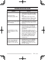
1
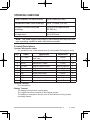
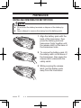
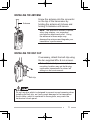
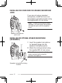
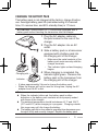
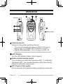
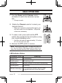
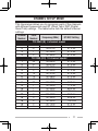
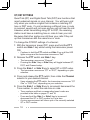
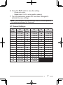
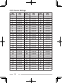
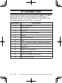
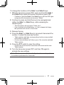
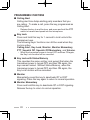
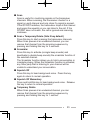
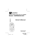
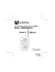
INSTRUCTION MANUAL
VHF FM TRANSCEIVER
TK-2300
UHF FM TRANSCEIVER
TK-3300
© B62-2159-00 (K, K2)
09 08 07 06 05 04 03 02 01 00
Thank You
We are grateful for your purchase of this Kenwood product and
welcome you to the Business Radio Service (BRS).
Your Kenwood 2-way Business Radio is called a “transceiver”,
meaning “transmitter & receiver”. We believe this easy-touse transceiver will provide you with dependable and reliable
communications. This Kenwood transceiver is a precision
device. Treat it with care, and you will enjoy years of reliable
operation.
Models Covered by this Manual
TK-2300 (K): 4-channel VHF FM Transceiver
TK-3300 (K): 4-channel UHF FM Transceiver
TK-2300 (K2): 16-channel VHF FM Transceiver
TK-3300 (K2): 16-channel UHF FM Transceiver
Features
• 4 channels (K) or 16 channels (K2) with 27 VHF operating
frequencies (TK-2300) or 89 UHF operating frequencies
(TK-3300) and 122 tone/ code settings for each channel
allowing you to ignore unwanted calls.
• Built in voice scrambler gives you complete privacy for your
conversations.
• Hands free operation when using an optional headset.
• Voice announcement lets you know which channel you have
selected and which settings you have made when reassigning
key functions and channel settings.
Operating Conditions
Open locations (no obstructions)
Up to 6 miles (9.6 km)
Residential areas (near buildings)
Up to 1.5 miles (2.4 km)
In steel/ concrete reinforced
buildings
Up to 250,000 square feet
(23,220 m2)
In high rises
Up to 20 floors
Note: The listed ranges are based on field testing and may vary with
your operating conditions and individual transceiver.
Terminal Descriptions
Speaker/ Microphone Jacks
It is possible to use a resin-based cover for the Speaker/ Microphone jacks.
NO.
Name
Description
1
PTT / RXD
2
MIC
External PTT Input / Serial
Data Input
External MIC Input
3
MICIN
Internal MIC Output
4
5
6
7
8
9
10
OPTDET
5M
AE
TXD
NC
SPO
SPI
External Option Detect
5V Output
GND
Serial Data Output
No Connection
Audio Input
Received Audio Output
Impedance
I/O
CMOS
I
1.8 kΩ
I
1.8 kΩ
O
High Impedance
100 Ω
GND
CMOS
−
8Ω
8Ω
I
O
−
O
−
I
O
Antenna Terminal
50 Ω impedance
Battery Terminal
The battery terminal uses a spring plate.
The negative terminal connects to the chassis ground.
The battery is mounted on the rear side of the transceiver using a latch
mounting method.
FCC License Information
Your Kenwood transceiver operates on communications
frequencies which are subject to FCC (Federal Communications
Commission) Rules & Regulations. FCC Rules require that all
operators using Private Land Mobile radio frequencies obtain a
radio license before operating their equipment. Application for
license must be made on FCC form 601, schedules D and H,
and Remittance form 159.
FAX: Forms can be obtained by fax from the FCC Fax-OnDemand system. Call 1-202-418-0177 from your fax machine
and request document number 000601 for the form, schedules,
and instructions.
MAIL: Forms can be ordered by telephone, and will be sent to
you by first class mail. Call the FCC Forms Hotline at
1-800-418-FORM (1-800-418-3676).
INTERNET: Form 601 and instructions can be downloaded
from the FCC Forms website at
http://www.fcc.gov/formpage.html
Before filling out your Form 601 application Technical Data
section, you must decide on which frequencies you will operate.
See the frequency charts on pages 14 and 15.
QUESTIONS? Call the FCC for license application questions
at 1-888-CALL-FCC (1-888-225-5322).
ii
One or more of the following statements may be
applicable:
FCC WARNING
This equipment generates or uses radio frequency energy. Changes
or modifications to this equipment may cause harmful interference
unless the modifications are expressly approved in the instruction
manual. The user could lose the authority to operate this equipment if
an unauthorized change or modification is made.
INFORMATION TO THE DIGITAL DEVICE USER REQUIRED BY
THE FCC
This equipment has been tested and found to comply with the limits
for a Class B digital device, pursuant to Part 15 of the FCC Rules.
These limits are designed to provide reasonable protection against
harmful interference in a residential installation.
This equipment generates, uses and can generate radio frequency
energy and, if not installed and used in accordance with the instructions,
may cause harmful interference to radio communications. However,
there is no guarantee that the interference will not occur in a particular
installation. If this equipment does cause harmful interference to
radio or television reception, which can be determined by turning the
equipment off and on, the user is encouraged to try to correct the
interference by one or more of the following measures:
• Reorient or relocate the receiving antenna.
• Increase the separation between the equipment and receiver.
• Connect the equipment to an outlet on a circuit different from that
to which the receiver is connected.
• Consult the dealer for technical assistance.
ATTENTION:
The RBRC Recycle seal found on Kenwood lithium-ion
(Li-ion) battery packs indicates Kenwood’s voluntary
participation in an industry program to collect and recycle
Li-ion batteries after their operating life has expired.
The RBRC program is an alternative to disposing Li-ion
batteries with your regular refuse or in municipal waste
streams, which is illegal in some areas.
For information on Li-ion battery recycling in your area, call (toll free)
1-800-8-BATTERY (1-800-822-8837).
Kenwood’s involvement in this program is part of our commitment to
preserve our environment and conserve our natural resources.
iii
Notices to the User
◆ Government law prohibits the operation of unlicensed radio
transmitters within the territories under government control.
◆ Illegal operation is punishable by fine and/or imprisonment.
◆ Refer service to qualified technicians only.
Safety: It is important that the operator is aware of, and
understands, hazards common to the operation of any
transceiver.
Precautions
•
•
•
•
•
•
•
•
•
•
•
•
Do not charge the transceiver and battery pack when they are wet.
Ensure that there are no metallic items located between the
transceiver and the battery pack.
Do not use options not specified by Kenwood.
If the die-cast chassis or other transceiver part is damaged, do not
touch the damaged parts.
If a headset or headphone is connected to the transceiver, reduce
the transceiver volume. Pay attention to the volume level when
turning the squelch off.
Do not place the microphone cable around your neck while near
machinery that may catch the cable.
Do not place the transceiver on unstable surfaces.
Ensure that the end of the antenna does not touch your eyes.
When the transceiver is used for transmission for many hours, the
radiator and chassis will become hot. Do not touch these locations
when replacing the battery pack.
Do not immerse the transceiver in water.
Always switch the transceiver power off before installing optional
accessories.
The charger is the device that disconnects the unit from the AC
mains line. The AC plug should be readily accessible.
iv
Turn the transceiver power off in the following locations:
• In explosive atmospheres (inflammable gas, dust particles,
metallic powders, grain powders, etc.).
• While taking on fuel or while parked at gasoline service stations.
• Near explosives or blasting sites.
• In aircrafts. (Any use of the transceiver must follow the instructions
and regulations provided by the airline crew.)
• Where restrictions or warnings are posted regarding the use of
radio devices, including but not limited to medical facilities.
• Near persons using pacemakers.
•
•
•
•
•
•
•
•
•
Do not disassemble or modify the transceiver for any reason.
Do not place the transceiver on or near airbag equipment while
the vehicle is running. When the airbag inflates, the transceiver
may be ejected and strike the driver or passengers.
Do not transmit while touching the antenna terminal or if
any metallic parts are exposed from the antenna covering.
Transmitting at such a time may result in a high-frequency burn.
If an abnormal odor or smoke is detected coming from the
transceiver, switch the transceiver power off immediately, remove
the battery pack from the transceiver, and contact your Kenwood
dealer.
Use of the transceiver while you are driving may be against traffic
laws. Please check and observe the vehicle regulations in your
area.
Do not expose the transceiver to extremely hot or cold conditions.
Do not carry the battery pack (or battery case) with metal objects,
as they may short the battery terminals.
Danger of explosion if the battery is incorrectly replaced; replace
only with the same type.
When operating the transceiver in areas where the air is dry, it is
easy to build up an electric charge (static electricity). When using
an earphone accessory in such conditions, it is possible for the
transceiver to send an electric shock through the earphone and to
your ear. We recommend you use only a speaker/microphone in
these conditions, to avoid electric shocks.
Information concerning the battery pack:
The battery pack includes flammable objects such as organic
solvent. Mishandling may cause the battery to rupture
producing flames or extreme heat, deteriorate, or cause other
forms of damage to the battery. Please observe the following
prohibitive matters.
•
•
•
•
•
•
Do not disassemble or reconstruct battery!
The battery pack has a safety function and protection circuit to
avoid danger. If they suffer serious damage, the battery may
generate heat or smoke, rupture, or burst into flame.
Do not short-circuit the battery!
Do not join the + and – terminals using any form of metal (such
as a paper clip or wire). Do not carry or store the battery pack in
containers holding metal objects (such as wires, chain-necklace or
hairpins). If the battery pack is short-circuited, excessive current will
flow and the battery may generate heat or smoke, rupture, or burst
into flame. It will also cause metal objects to heat up.
Do not incinerate or apply heat to the battery!
If the insulator is melted, the gas release vent or safety function is
damaged, or the electrolyte is ignited, the battery may generate
heat or smoke, rupture, or burst into flame.
Do not use or leave the battery near fire, stoves, or other heat
generators (areas reaching over 80°C/ 176°F)!
If the polymer separator is melted due to high temperature, an
internal short-circuit may occur in the individual cells and the
battery may generate heat or smoke, rupture, or burst into flame.
Do not immerse the battery in water or get it wet by other
means!
If the battery’s protection circuit is damaged, the battery may
charge at extreme current (or voltage) and an abnormal chemical
reaction may occur. The battery may generate heat or smoke,
rupture, or burst into flame.
Do not charge the battery near fire or under direct sunlight!
If the battery’s protection circuit is damaged, the battery may
charge at extreme current (or voltage) and an abnormal chemical
reaction may occur. The battery may generate heat or smoke,
rupture, or burst into flame.
vi
•
•
•
•
•
•
•
Use only the specified charger and observe charging
requirements!
If the battery is charged in unspecified conditions (under high
temperature over the regulated value, excessive high voltage or
current over regulated value, or with a remodeled charger), it may
overcharge or an abnormal chemical reaction may occur. The
battery may generate heat or smoke, rupture, or burst into flame.
Do not pierce the battery with any object, strike it with an
instrument, or step on it!
This may break or deform the battery, causing a short-circuit. The
battery may generate heat or smoke, rupture, or burst into flame.
Do not jar or throw the battery!
An impact may cause the battery to leak, generate heat or smoke,
rupture, and/or burst into flame. If the battery’s protection circuit
is damaged, the battery may charge at an abnormal current (or
voltage), and an abnormal chemical reaction may occur. The
battery may generate heat or smoke, rupture, or burst into flame.
Do not use the battery pack if it is damaged in any way!
The battery may generate heat or smoke, rupture, or burst into
flame.
Do not solder directly onto the battery!
If the insulator is melted or the gas release vent or safety function
is damaged, the battery may generate heat or smoke, rupture, or
burst into flame.
Do not reverse the battery polarity (and terminals)!
When charging a reversed battery, an abnormal chemical reaction
may occur. In some cases, an unexpected large amount of
current may flow upon discharging. The battery may generate
heat or smoke, rupture, or burst into flame.
Do not reverse-charge or reverse-connect the battery!
The battery pack has positive and negative poles. If the battery
pack does not smoothly connect with a charger or operating
equipment, do not force it; check the polarity of the battery. If the
battery pack is reverse-connected to the charger, it will be reversecharged and an abnormal chemical reaction may occur. The
battery may generate heat or smoke, rupture, or burst into flame.
vii
•
Do not touch a ruptured and leaking battery!
If the electrolyte liquid from the battery gets into your eyes, wash
your eyes with fresh water as soon as possible, without rubbing
your eyes. Go to the hospital immediately. If left untreated, it may
cause eye-problems.
•
Do not charge the battery for longer than the specified time!
If the battery pack has not finished charging even after the
regulated time has passed, stop it. The battery may generate heat
or smoke, rupture, or burst into flame.
Do not place the battery pack into a microwave or high
pressure container!
The battery may generate heat or smoke, rupture, or burst into
flame.
Keep ruptured and leaking battery packs away from fire!
If the battery pack is leaking (or the battery emits a bad odor),
immediately remove it from flammable areas. Electrolyte leaking
from battery can easily catch on fire and may cause the battery to
generate smoke or burst into flame.
Do not use an abnormal battery!
If the battery pack emits a bad odor, appears to have different
coloring, is deformed, or seems abnormal for any other reason,
remove it from the charger or operating equipment and do not use
it. The battery may generate heat or smoke, rupture, or burst into
flame.
•
•
•
viii
CONTENTS
UNPACKING AND CHECKING EQUIPMENT........................... 1
PREPARATION........................................................... 2
ORIENTATION............................................................ 6
BASIC OPERATIONS.................................................... 8
VOICE OPERATED TRANSMISSION (VOX)........................... 9
BACKGROUND OPERATIONS......................................... 10
CHANNEL SETUP MODE............................................... 11
KEY ASSIGNMENT MODE............................................. 20
TROUBLESHOOTING GUIDE.......................................... 25
ALL RESET MODE...................................................... 26
OPTIONAL ACCESSORIES............................................. 26
UNPACKING AND CHECKING EQUIPMENT
Carefully unpack the transceiver. If any of the items listed
below are missing or damaged, file a claim with the carrier
immediately.
Supplied Accessories
•
•
•
•
•
•
Battery charger/ AC adapter (KSC-35).................................... 1
Li-ion Battery pack (KNB-45L)................................................. 1
Speaker/ microphone jack cover............................................. 1
Speaker/ microphone locking bracket..................................... 1
Belt clip (KBH-10).................................................................... 1
Screw set
• M3 x 6 mm (Black)................................................................... 1
• M3 x 8 mm............................................................................... 2
• Warranty card.......................................................................... 1
• Instruction manual................................................................... 1
Note: Refer to "PREPARATION" for accessory installation
instructions.
PREPARATION
Installing/ Removing the Battery Pack
◆ Do not short the battery terminals or dispose of the battery by
fire.
◆ Never attempt to remove the casing from the battery pack.
1 Align the battery pack with the
back of the transceiver, then
press the battery pack and
transceiver firmly together until
the release latch on the base of
the transceiver locks.
2 To remove the battery pack, lift
the safety catch on the base of
the transceiver, then press the
release latch underneath the
safety catch.
3 While pressing the release
latch, pull the battery pack
away from the transceiver.
Installing the Antenna
Antenna
Screw the antenna into the connector
on the top of the transceiver by
holding the antenna at its base and
turning it clockwise until secure.
Note: The antenna is neither a handle,
a key ring retainer, nor a speaker/
microphone attachment point. Using
the antenna in these ways may
damage the antenna and degrade your
transceiver’s performance.
Installing the Belt Clip
If necessary, attach the belt clip using
the two supplied M3 x 8 mm screws.
Note: If the belt clip is not installed, its
mounting location may get hot during
continuous transmission or when left
sitting in a hot environment.
Belt clip
Do not use glue which is designed to prevent screw loosening when
installing the belt clip, as it may cause damage to the transceiver.
Acrylic ester, which is contained in these glues, may crack the
transceiver’s back panel.
Installing the Cover over the Speaker/ Microphone
Jacks
If you are not using a speaker/
microphone, install the cover over
the speaker/ microphone jacks using
the supplied M3 x 6 mm screw.
Note: To keep the transceiver water
resistant, you must cover the speaker/
microphone jacks with the supplied
cover.
Speaker/ microphone
jack cover
Installing the Optional Speaker/ Microphone
(or Headset)
1 Insert the speaker/ microphone
(or headset) plugs into the
speaker/ microphone jacks.
2 Attach the locking bracket using
the supplied M3 x 6 mm screw.
Note: The transceiver is not fully
water resistant while using the
speaker/ microphone.
Speaker/ microphone locking
bracket
Charging the Battery Pack
The battery pack is not charged at the factory; charge it before
use. Average battery pack life (calculated using 5% transmit
time, 5% receive time, and 90% standby time) is 17 hours.
ATTENTION: Always switch OFF a transceiver equipped with a
battery pack before inserting the transceiver into the charger.
1 Plug the AC adapter cable into
the jack located on the rear of the
charger.
2 Plug the AC adapter into an AC
outlet.
3 Slide a battery pack or a transceiver
equipped with a battery pack into
the charging slot of the charger.
• Make sure the metal contacts of the
battery pack mate securely with the
charger terminals.
• The indicator lights red and charging
begins.
Charging slot
Indicator
4 When charging is completed, the
indicator lights green. Remove the
battery pack or the transceiver from
the charging slot of the charger.
• It takes approximately 3 hours to charge the battery pack.
• When the charger will not be used for a long time, unplug the AC
adapter from the AC outlet.
Note:
◆ When the indicator blinks red, the battery pack is either
defective or the battery pack contacts are not properly mated
with those of the charger.
◆ The ambient temperature should be between 41°F and 104°F
(5°C and 40°C) while charging is in progress. Charging outside
this range may not fully charge the battery.
◆ The battery pack life is over when its operating time decreases even
though it is fully and correctly charged. Replace the battery pack.
ORIENTATION
Antenna
Battery pack
Channel selector
Rotate to change the operating channel.
• To change the operating frequency or QT/DQT settings of a
channel, refer to “CHANNEL SETUP MODE” on page 11.
• Channel Announcement: When changing channels, the
transceiver will announce the newly selected channel number.
LED indicator
For the LED indicator status, refer to page 8.
Power switch/ Volume control
Turn clockwise to switch the transceiver ON. To switch the
transceiver OFF, turn counterclockwise until a click sounds.
Rotate to adjust the volume level.
PTT (Push to Talk) switch
Press and hold, then speak into the microphone to transmit.
Side 1 key
Press to activate its programmable function.
The default setting is Super Lock.
• For function descriptions and details on how to change the
function of the Side 1 key, refer to “KEY ASSIGNMENT MODE”
on page 20.
Side 2 key
Press to activate its programmable function.
The default setting is Scan + Temporary Delete.
• For function descriptions and details on how to change the
function of the Side 2 key, refer to “KEY ASSIGNMENT MODE”
on page 20.
Speaker/ microphone jacks
Insert the Speaker/ microphone or Headset plug into this
jack.
BASIC OPERATIONS
1 Turn the Power switch/ Volume control
clockwise to switch the transceiver power
ON.
• A beep sounds.
2 Rotate the Channel selector to select your
desired channel.
• When you receive an appropriate signal, you
will hear audio from the speaker. Adjust the
volume as necessary.
3 To make a call, press and hold the PTT
switch, then speak into the microphone using
your normal speaking voice.
• Hold the microphone approximately 1.5 inches
(3 to 4 cm) from your lips.
4 Release the PTT switch to receive.
Note: When the battery pack voltage becomes too
low, the Low Battery Warning sounds an alert tone
every 30 seconds and the LED indicator blinks red.
LED Indicator Status
Indicator Color
Meaning
Lights red
Transmitting
Lights green
Receiving a call
Blinks red
Battery power is low while transmitting
Blinks green
Scanning
Blinks red/orange
The selected channel has not been
programmed and cannot be used.
VOICE OPERATED TRANSMISSION (VOX)
VOX operation allows you to transmit hands-free. VOX can
only be used if you are using a supported headset. This
function can be turned off for specific channels.
To activate VOX and set the VOX Gain level, perform the
following steps:
1 Connect the headset to the transceiver .
• The VOX function does not activate when a headset is not
connected to the accessory terminal of the transceiver.
2 With the transceiver power OFF, press and hold the Side 1
key while turning the transceiver power ON.
3 Continue to hold the Side 1 key until a beep sounds.
• The LED indicator lights turn orange.
• When the Side 1 key is released, the transceiver will
announces the VOX Gain level (the default level is OFF, so, a
double beep sounds).
4 Press the Side 1 key to select the VOX Gain level of the radio
(from 1~10 or Off).
• Press the Side 2 key to turn VOX ON/OFF for the current
channel (you can change this setting for each channel by
selecting a channel with the Channel selector). When turned
ON, a beep sounds. When turned OFF, a double beep sounds.
5 Press the PTT switch to save the setting.
• A beep will sound.
• The transceiver announces the new VOX Gain level.
6 Turn the transceiver power OFF and then ON again to
activate VOX.
Note:
◆ The transceiver will automatically return to normal operation if
no action is performed for 5 seconds.
◆ VOX Gain level 1 is the least sensitive and VOX Gain level 10 is
the most sensitive.
◆ If a headset is connected to the transceiver while the VOX
function is switched ON and the VOX Gain level is configured
to a higher, more sensitive level, louder received signals may
cause the transceiver to start transmission.
BACKGROUND OPERATIONS
Time-Out Timer (TOT)
The Time-out Timer prevent callers from using a channel for an
extended duration (60 seconds). If you continuously transmit
for the duration, transmission will stop and an alert tone will
sound. To stop the tone, release the PTT switch.
Low Battery Warning
While operating the transceiver, the Low Battery Warning
sounds an alert tone every 30 seconds and the LED indicator
blinks red when the battery needs recharged or replaced.
Channel Announcement
When changing the channel, the transceiver will announce the
newly selected channel number. Likewise, the transceiver will
announce the current channel after you turn the transceiver
power ON.
10
CHANNEL SETUP MODE
This transceiver allows you to reprogram each of the channels
with different frequencies and QT (Quiet Talk)/ DQT (Digital
Quiet Talk) settings. The table below lists the default channel
settings.
Channel
Number
1
2
3
4
1
2
3
4
5
6
7
8
9
10
11
12
13
14
15
16
Table
Number
Frequency (MHz)
QT/DQT Setting
TK-2300 (K) 4 channel model
20
154.4900
67.0 Hz
67.0 Hz
21
154.5150
1
151.6250
67.0 Hz
2
151.9550
67.0 Hz
TK-2300 (K2) 16 channel model
20
154.4900
67.0 Hz
21
154.5150
67.0 Hz
1
151.6250
67.0 Hz
2
151.9550
67.0 Hz
10
151.5125
67.0 Hz
12
151.6850
67.0 Hz
15
151.7750
67.0 Hz
26
158.4000
67.0 Hz
1
151.6250
77.0 Hz
1
151.6250
88.5 Hz
1
151.6250
179.9 Hz
2
151.9550
82.5 Hz
2
151.9550
94.8 Hz
2
151.9550
179.9 Hz
5
151.7000
67.0 Hz
6
151.7600
67.0 Hz
11
Channel
Number
1
2
3
4
1
2
3
4
5
6
7
8
9
10
11
12
13
14
15
16
Table
Number
Frequency (MHz)
QT/DQT Setting
TK-3300 (K) 4 channel model
2
464.5500
8
467.9250
9
461.0375
10
461.0625
TK-3300 (K2) 16 channel model
2
464.5500
8
467.9250
9
461.0375
10
461.0625
11
461.0875
12
461.1125
13
461.1375
14
461.1625
1
464.5000
3
467.7625
4
467.8125
5
467.8500
6
467.8750
7
467.9000
15
461.1875
16
461.2125
67.0 Hz
67.0 Hz
67.0 Hz
67.0 Hz
67.0 Hz
67.0 Hz
67.0 Hz
67.0 Hz
67.0 Hz
67.0 Hz
67.0 Hz
67.0 Hz
67.0 Hz
67.0 Hz
67.0 Hz
67.0 Hz
67.0 Hz
67.0 Hz
67.0 Hz
67.0 Hz
Note: Due to FCC regulations, the default values of TK-2300 (VHF)
are different from TK-2200 (VHF) series. Make sure to choose a
compatible frequency to interoperate with each other.
12
CHANNEL OPERATING FREQUENCIES
To change the operating frequency of a channel:
1 With the transceiver power OFF, press and hold the PTT
switch and Side 1 key while turning the transceiver power
ON.
• Continue to hold the PTT switch and Side 1 key until the LED
lights orange and the transceiver announces “Self”.
2 Release the PTT switch and Side 1 key.
• The transceiver announces “Channel”.
• Pressing the Side 1 key or Side 2 key will toggle between QT,
DQT, and Channel setup.
3 Press and release the PTT switch, then rotate the Channel
selector to your desired channel.
• Upon pressing and releasing the PTT switch, a beep will sound
and the transceiver announces “Table zero”.
4 Press the Side 1 or Side 2 key to increment/ decrement the
Table number, to select the new channel frequency.
• Press and hold the Side 1 or Side 2 key to increment/
decrement the number by 5 at a time.
• Table numbers and their corresponding operating frequencies
are provided in the table on page 14.
• A voice announcement will inform you of the currently selected
Table number.
5 Press the PTT switch to save the setting.
• A beep will sound.
• Repeat steps 3 to 5 to set up another channel.
6 Turn the transceiver power OFF and then ON again to
activate the new settings.
Note: The transceiver will automatically return to normal operation
if no action is performed for 5 seconds.
13
TK-2300
Operating
Table Number Frequency (MHz)
0
1
2
3
4
5
6
7
8
9
10
11
12
13
OFF
151.6250
151.9550
152.8850
152.9150
151.7000
151.7600
152.9450
151.8350
151.8050
151.5125
151.6550
151.6850
151.7150
TK-3300
Operating
Table Number Frequency (MHz)
0
1
2
3
4
5
6
7
8
9
10
11
12
13
14
OFF
464.5000
464.5500
467.7625
467.8125
467.8500
467.8750
467.9000
467.9250
461.0375
461.0625
461.0875
461.1125
461.1375
TK-2300
Operating
Table Number Frequency (MHz)
14
15
16
17
18
19
20
21
22
23
24
25
26
27
151.7450
151.7750
151.8650
151.8950
151.9250
152.7000
154.4900
154.5150
154.5275
154.5400
153.0050
154.6550
158.4000
158.4075
TK-3300
Operating
Table Number Frequency (MHz)
14
15
16
17
18
19
20
21
22
23
24
25
26
27
461.1625
461.1875
461.2125
461.2375
461.2625
461.2875
461.3125
461.3375
461.3625
462.7625
462.7875
462.8125
462.8375
462.8625
TK-3300
Operating
Table Number Frequency (MHz)
28
29
30
31
32
33
34
35
36
37
38
39
40
41
42
43
44
45
46
47
48
49
50
51
52
53
54
55
56
57
58
462.8875
462.9125
464.4875
464.5125
464.5375
464.5625
466.0375
466.0625
466.0875
466.1125
466.1375
466.1625
466.1875
466.2125
466.2375
466.2625
466.2875
466.3125
466.3375
466.3625
467.7875
467.8375
467.8625
467.8875
467.9125
469.4875
469.5125
469.5375
469.5625
462.1875
462.4625
TK-3300
Operating
Table Number Frequency (MHz)
59
60
61
62
63
64
65
66
67
68
69
70
71
72
73
74
75
76
77
78
79
80
81
82
83
84
85
86
87
88
89
462.4875
462.5125
467.1875
467.4625
467.4875
467.5125
451.1875
451.2375
451.2875
451.3375
451.4375
451.5375
451.6375
452.3125
452.5375
452.4125
452.5125
452.7625
452.8625
456.1875
456.2375
456.2875
456.3375
456.4375
456.5375
456.6375
457.3125
457.4125
457.5125
457.7625
457.8625
15
QT/ DQT SETTINGS
Quiet Talk (QT) and Digital Quiet Talk (DQT) are functions that
reject undesired signals on your channel. You will hear a call
only when you receive a signal that contains a matching QT
tone or DQT code. If a call containing a different tone or code
is received, squelch will not open and you will not hear the call.
Likewise, when transmitting using QT or DQT, the receiving
station must have a matching tone or code to hear your call.
Be aware that other parties can still hear your calls if they set
up their transceiver with the same tone or code.
To change the QT/DQT settings of a channel:
1 With the transceiver power OFF, press and hold the PTT
switch and Side 1 key while turning the transceiver power
ON.
• Continue to hold the PTT switch and Side 1 key until the LED
lights orange and the transceiver announces “Self”.
2 Release the PTT switch and Side 1 key.
• The transceiver announces “Channel”.
• Pressing the Side 1 key or Side 2 key will toggle between QT,
DQT, and Channel setup.
3 Press the Side 1 or Side 2 key to select QT or DQT setup.
• The transceiver announces “QT” or “DQT”, depending on your
selection.
4 Press and release the PTT switch, then rotate the Channel
selector to your desired channel.
• Upon releasing the PTT switch, the transceiver announces “QT
One” or “DQT One”, depending on your selection.
5 Press the Side 1 or Side 2 key to increment/ decrement the
Tone number, to select the new tone or code.
• Tone numbers and their corresponding tones/ codes are
provided in the table on pages 17 and 18.
• Press and hold the Side 1 or Side 2 key to increment/
decrement the QT or DQT number by 5 at a time.
• A voice announcement will inform you of the currently selected
QT or DQT number.
16
6 Press the PTT switch to save the setting.
• A beep will sound.
• Repeat steps 3 to 6 to set up another channel.
7 Turn the transceiver power OFF and then ON again to
activate the new settings.
Note: The transceiver will automatically return to normal operation
if no action is performed for 5 seconds.
QT Channel Settings:
QT
Number
QT
Frequency
QT
Number
QT
Frequency
QT
Number
QT
Frequency
1
2
3
4
5
6
7
8
9
10
11
12
13
14
67.0 Hz
71.9 Hz
74.4 Hz
77.0 Hz
79.7 Hz
82.5 Hz
85.4 Hz
88.5 Hz
91.5 Hz
94.8 Hz
97.4 Hz
100.0 Hz
103.5 Hz
107.2 Hz
15
16
17
18
19
20
21
22
23
24
25
26
27
28
110.9 Hz
114.8 Hz
118.8 Hz
123.0 Hz
127.3 Hz
131.8 Hz
136.5 Hz
141.3 Hz
146.2 Hz
151.4 Hz
156.7 Hz
162.2 Hz
167.9 Hz
173.8 Hz
29
30
31
32
33
34
35
36
37
38
39
off
179.9 Hz
186.2 Hz
192.8 Hz
203.5 Hz
210.7 Hz
218.1 Hz
225.7 Hz
233.6 Hz
241.8 Hz
250.3 Hz
69.3 Hz
OFF
17
DQT Channel Settings:
DQT
Number
DQT
Code
DQT
Number
DQT
Code
DQT
Number
DQT
Code
1
2
3
4
5
6
7
8
9
10
11
12
13
14
15
16
17
18
19
20
21
22
23
24
25
26
27
28
D023N
D025N
D026N
D031N
D032N
D043N
D047N
D051N
D054N
D065N
D071N
D072N
D073N
D074N
D114N
D115N
D116N
D125N
D131N
D132N
D134N
D143N
D152N
D155N
D156N
D162N
D165N
D172N
29
30
31
32
33
34
35
36
37
38
39
40
41
42
43
44
45
46
47
48
49
50
51
52
53
54
55
56
D174N
D205N
D223N
D226N
D243N
D244N
D245N
D251N
D261N
D263N
D265N
D271N
D306N
D311N
D315N
D331N
D343N
D346N
D351N
D364N
D365N
D371N
D411N
D412N
D413N
D423N
D431N
D432N
57
58
59
60
61
62
63
64
65
66
67
68
69
70
71
72
73
74
75
76
77
78
79
80
81
82
83
off
D445N
D464N
D465N
D466N
D503N
D506N
D516N
D532N
D546N
D565N
D606N
D612N
D624N
D627N
D631N
D632N
D654N
D662N
D664N
D703N
D712N
D723N
D731N
D732N
D734N
D743N
D754N
OFF
18
CHANNEL CONFIRMATION MODE
To confirm your channel settings:
1 With the transceiver power OFF, press and hold the PTT
switch while turning the transceiver power ON.
• Continue to hold the PTT switch until the LED lights orange and
the transceiver announces “Confirm”.
2 Release the PTT switch.
• Transceiver announces the channel table number, tone
number, scrambler and VOX settings of the selected channel.
3 Rotate the Channel selector to your desired channel within
5 seconds, otherwise the operation will cancel.
• Transceiver announces the channel table number, tone
number, scrambler and VOX settings of the selected channel.
Note: The transceiver will automatically return to normal operation
if no action is performed for 5 seconds.
19
KEY ASSIGNMENT MODE
This transceiver allows you to reprogram the Side 1 and Side
2 keys with any of the functions listed in the table below.
Explanations on the use of each function are provided under
“Programmable Functions”, on page 22.
Table Number
Function Name
0
None (no function)
1
Calling Alert
2
Key Lock
3
Key Lock with Status Memory
4
Monitor
5
Monitor Momentary
6
Scan
7
Scan + Temporary Delete (Side 2 key default)
8
Scrambler
9
Squelch Off
10
Squelch Off Momentary
11
Temporary Delete
12
Super Lock (Side 1 key default)
13
Low Transmit Power
20
To change the functions of the Side 1 and Side 2 keys:
1 With the transceiver power OFF, press and hold the Side 1
and Side 2 keys while turning the transceiver power ON.
• Continue to hold the Side 1 and Side 2 keys until the LED lights
orange and the transceiver announces “Setup”.
2 Continue to press and hold the key to be reprogrammed
(either the Side 1 or Side 2 key), while releasing the
remaining key.
• The transceiver will announce “Table zero”.
• If you continue to hold both keys, or if you release both keys,
the operation will cancel in 5 seconds.
3 Release the key.
4 Press the Side 1 or Side 2 key to increment/ decrement the
number, to select the new key function.
• Table numbers and their corresponding functions are provided
in the table on page 20.
• A voice announcement will inform you of the currently selected
Table number.
5 Press the PTT switch to save the setting.
• A beep will sound and the transceiver will announce the new
Table number.
6 Turn the transceiver power OFF and then ON again to
activate the new settings.
Note: The transceiver will automatically return to normal operation
if no action is performed for 5 seconds.
21
Programmable Functions
■ Calling Alert
Calling alert tone helps alerting party members that you
are calling. To make a call, press the key programmed as
Calling Alert.
• Release the key to end the tone, and press and hold the PTT
switch to transmit and speak into the microphone.
■ Key Lock
Press and hold this key for 1 second to lock/ unlock the
transceiver keys.
The following keys/ functions can still be used when Key
Lock is active:
Calling Alert, Key Lock, Monitor, Monitor Momentary,
PTT, Squelch Off, Squelch Off Momentary, and Volume.
• When the transceiver power is turned OFF and then ON again,
the Key Lock function will be cancelled.
■ Key Lock with Status Memory
This operates the same as Key Lock except that when the
transceiver power is turned OFF and then ON again, the
keys remain locked. Without Status Memory, when the
transceiver power is turned OFF and then ON again, the
Key Lock function will be cancelled.
■ Monitor
Momentarily press this key to deactivate QT or DQT
signaling. Press the key again to return to normal operation.
■ Monitor Momentary
Press and hold this key to deactivate QT or DQT signaling.
Release the key to return to normal operation.
22
■ Scan
Scan is useful for monitoring signals on the transceiver
channels. When scanning, the transceiver checks for a
signal on each channel and only stops if a signal is present.
If the QT/DQT matches, the transceiver stops at the channel
and opens the squelch so you can listen to the call. If the
QT/DQT does not match, the call is ignored and scanning
continues.
■ Scan + Temporary Delete (Side 2 key default)
Press this key to start scanning the transceiver channels.
When Scan pauses at an undesired channel, you can
remove that channel from the scanning sequence by
pressing and holding this key for 3 seconds.
■ Scrambler
Press this key to activate (a single beep sounds) and
deactivate (a double beep sounds) the scrambler function of
the selected channel.
The Scrambler function allows you to hold a conversation in
complete privacy. When the Scrambler function is activated,
any other party that is listening to your channel will be
unable to understand your conversation.
■ Squelch Off
Press this key to hear background noise. Press the key
again to return to normal operation.
■ Squelch Off Momentary
Press and hold this key to hear background noise. Release
the key to return to normal operation.
■ Temporary Delete
When Scan pauses at an undesired channel, you can
remove that channel from the scanning sequence by
pressing and holding this key for 1 second.
23
■ Super Lock (Side 1 key default)
Super Lock locks the same keys as Key Lock. Press and
hold this key for 4 seconds to lock the transceiver keys. To
deactivate Super Lock, with the transceiver power OFF,
press and hold the Side 2 key for 2 seconds while turning
the transceiver power ON.
• When the LED lights orange, release the Side 2 key.
A confirmation tone will sound.
■ Low Transmit Power
Press this key to change the transmit power to low power.
Each time you press this key, the transmit power toggles
between high and low.
24
TROUBLESHOOTING GUIDE
Problem
Solution
•
Cannot turn the
transceiver power ON.
Battery power dies shortly
after charging.
Cannot talk to or hear
other members in your
group.
•
•
The battery pack life is finished.
Replace the battery pack with a
new one.
•
Make sure you are using the
same frequency and QT/DQT
settings as the other members in
your group.
Other group members may be
using the Scrambler function. Turn
on your transceiver’s Scrambler.
Other group members may be
too far away. Make sure you
are within range of the other
transceivers.
•
•
Other voices (besides
group members’) are
present on the channel.
The battery pack may be dead.
Recharge or replace the battery
pack.
The battery pack may not be
installed correctly. Remove the
battery pack and install again.
•
Change the QT/DQT settings.
Make sure all group members
change the settings on their
transceivers to match the new
QT/DQT setting.
25
ALL RESET MODE
At some point in time, you may desire to reset the transceiver
settings to their default values. This function will reset all
channels to their default frequencies and QT/DQT, the VOX
function to its default status, and all keys to their default
functions.
To reset the transceiver:
1 With the transceiver power OFF, press and hold the PTT
switch, the Side 1 key, and the Side 2 key while turning the
transceiver power ON.
• Continue to hold the keys for 2 seconds, until the LED lights
orange.
2 Release the keys.
• The keys must be released within 1 second after the LED lights
orange, otherwise All Reset Mode will cancel.
• The transceiver announces “Confirm” and returns to normal
operation.
OPTIONAL ACCESSORIES
•
•
•
•
•
•
•
•
•
KMC-21 (Speaker/ microphone)
KMC-45 (Speaker/ microphone)
KHS-1 (Headset)
KHS-22 (Headset)
KNB-45L (Li-ion battery pack)
KSC-35 (Rapid charger)
KSC-356 (Multiple charger)
KBH-10 (Belt clip)
KWR-1 (Water resistant bag)
26