1
TK-2302/ TK-2302V
TK-3302/ TK-3302U
VHF FM TRANSCEIVER/
UHF FM TRANSCEIVER
INSTRUCTION MANUAL
ÉMETTEUR-RÉCEPTEUR FM VHF/
ÉMETTEUR-RÉCEPTEUR FM UHF
MODE D’EMPLOI
TRANSCEPTOR FM VHF/
TRANSCEPTOR FM UHF
MANUAL DE INSTRUCCIONES
© B62-2139-00 (K, P)
09 08 07 06 05 04 03 02 01 00
TK-2302/ TK-2302V
TK-3302/ TK-3302U
INSTRUCTION MANUAL
ENGLISH
VHF FM TRANSCEIVER/
UHF FM TRANSCEIVER
ATTENTION:
The RBRC Recycle seal found on Kenwood lithium-ion
(Li-ion) battery packs indicates Kenwood’s voluntary
participation in an industry program to collect and recycle
Li-ion batteries after their operating life has expired.
The RBRC program is an alternative to disposing Li-ion
batteries with your regular refuse or in municipal waste
streams, which is illegal in some areas.
For information on Li-ion battery recycling in your area, call (toll free)
1-800-8-BATTERY (1-800-822-8837).
Kenwood’s involvement in this program is part of our commitment to
preserve our environment and conserve our natural resources.
ATTENTION:
The RBRC Recycle seal found on Kenwood nickel
metal hydride (Ni-MH) battery packs indicates Kenwood’
s voluntary participation in an industry program to collect
and recycle Ni-MH batteries after their operating life
has expired. The RBRC program is an alternative to
disposing Ni-MH batteries with your regular refuse or in
municipal waste streams, which is illegal in some areas.
For information on Li-ion battery recycling in your area, call (toll free)
1-800-8-BATTERY (1-800-822-8837).
Kenwood’s involvement in this program is part of our commitment to
preserve our environment and conserve our natural resources.
Thank You
We are grateful you have chosen Kenwood for your land
mobile radio applications.
Notices to the User
◆ Government law prohibits the operation of unlicensed radio
transmitters within the territories under government control.
◆ Illegal operation is punishable by fine and/or imprisonment.
◆ Refer service to qualified technicians only.
Safety: It is important that the operator is aware of, and
understands, hazards common to the operation of any
transceiver.
Terminal Descriptions
Speaker/ Microphone Jacks
It is possible to use a resin-based cover for the Speaker/ Microphone jacks.
NO.
Name
Description
1
PTT / RXD
2
MIC
External PTT Input / Serial
Data Input
External MIC Input
3
MICIN
Internal MIC Output
4
5
6
7
8
9
10
OPTDET
5M
AE
TXD
NC
SPO
SPI
External Option Detect
5V Output
GND
Serial Data Output
No Connection
Audio Input
Received Audio Output
Impedance
I/O
CMOS
I
1.8 kΩ
I
1.8 kΩ
O
High Impedance
100 Ω
GND
CMOS
−
8Ω
8Ω
I
O
−
O
−
I
O
Antenna Terminal
50 Ω impedance
Battery Terminal
The battery terminal uses a spring plate.
The negative terminal connects to the chassis ground.
The battery is mounted on the rear side of the transceiver using a latch
mounting method.
One or more of the following statements may be
applicable:
FCC WARNING
This equipment generates or uses radio frequency energy.
Changes or modifications to this equipment may cause harmful
interference unless the modifications are expressly approved in the
instruction manual. The user could lose the authority to operate this
equipment if an unauthorized change or modification is made.
INFORMATION TO THE DIGITAL DEVICE USER REQUIRED BY
THE FCC
This equipment has been tested and found to comply with the limits
for a Class B digital device, pursuant to Part 15 of the FCC Rules.
These limits are designed to provide reasonable protection against
harmful interference in a residential installation.
This equipment generates, uses and can generate radio frequency
energy and, if not installed and used in accordance with the
instructions, may cause harmful interference to radio communications.
However, there is no guarantee that the interference will not occur
in a particular installation. If this equipment does cause harmful
interference to radio or television reception, which can be determined
by turning the equipment off and on, the user is encouraged to try to
correct the interference by one or more of the following measures:
• Reorient or relocate the receiving antenna.
• Increase the separation between the equipment and receiver.
• Connect the equipment to an outlet on a circuit different from
that to which the receiver is connected.
• Consult the dealer for technical assistance.
Precautions
•
•
•
•
•
•
•
•
•
•
•
•
Do not charge the transceiver and battery pack when they are wet.
Ensure that there are no metallic items located between the
transceiver and the battery pack.
Do not use options not specified by Kenwood.
If the die-cast chassis or other transceiver part is damaged, do not
touch the damaged parts.
If a headset or headphone is connected to the transceiver, reduce
the transceiver volume. Pay attention to the volume level when
turning the squelch off.
Do not place the microphone cable around your neck while near
machinery that may catch the cable.
Do not place the transceiver on unstable surfaces.
Ensure that the end of the antenna does not touch your eyes.
When the transceiver is used for transmission for many hours, the
radiator and chassis will become hot. Do not touch these locations
when replacing the battery pack.
Do not immerse the transceiver in water.
Always switch the transceiver power off before installing optional
accessories.
The charger is the device that disconnects the unit from the AC
mains line. The AC plug should be readily accessible.
ii
Turn the transceiver power off in the following locations:
• In explosive atmospheres (inflammable gas, dust particles, metallic
powders, grain powders, etc.).
• While taking on fuel or while parked at gasoline service stations.
• Near explosives or blasting sites.
• In aircrafts. (Any use of the transceiver must follow the instructions
and regulations provided by the airline crew.)
• Where restrictions or warnings are posted regarding the use of
radio devices, including but not limited to medical facilities.
• Near persons using pacemakers.
•
•
•
•
•
•
•
•
Do not disassemble or modify the transceiver for any reason.
Do not place the transceiver on or near airbag equipment while the
vehicle is running. When the airbag inflates, the transceiver may
be ejected and strike the driver or passengers.
Do not transmit while touching the antenna terminal or if any
metallic parts are exposed from the antenna covering. Transmitting
at such a time may result in a high-frequency burn.
If an abnormal odor or smoke is detected coming from the
transceiver, switch the transceiver power off immediately, remove
the battery pack from the transceiver, and contact your Kenwood
dealer.
Use of the transceiver while you are driving may be against traffic
laws. Please check and observe the vehicle regulations in your
area.
Do not expose the transceiver to extremely hot or cold conditions.
Do not carry the battery pack (or battery case) with metal objects,
as they may short the battery terminals.
When operating the transceiver in areas where the air is dry, it is
easy to build up an electric charge (static electricity). When using
a earphone accessory in such conditions, it is possible for the
transceiver to send an electric shock through the earphone and to
your ear. We recommend you use only a speaker/microphone in
these conditions, to avoid electric shocks.
iii
Information concerning the battery pack:
The battery pack includes flammable objects such as organic
solvent. Mishandling may cause the battery to rupture
producing flames or extreme heat, deteriorate, or cause other
forms of damage to the battery. Please observe the following
prohibitive matters.
•
•
•
•
•
•
Do not disassemble or reconstruct battery!
The battery pack has a safety function and protection circuit to
avoid danger. If they suffer serious damage, the battery may
generate heat or smoke, rupture, or burst into flame.
Do not short-circuit the battery!
Do not join the + and – terminals using any form of metal (such
as a paper clip or wire). Do not carry or store the battery pack in
containers holding metal objects (such as wires, chain-necklace or
hairpins). If the battery pack is short-circuited, excessive current will
flow and the battery may generate heat or smoke, rupture, or burst
into flame. It will also cause metal objects to heat up.
Do not incinerate or apply heat to the battery!
If the insulator is melted, the gas release vent or safety function is
damaged, or the electrolyte is ignited, the battery may generate
heat or smoke, rupture, or burst into flame.
Do not use or leave the battery near fire, stoves, or other heat
generators (areas reaching over 80°C/ 176°F)!
If the polymer separator is melted due to high temperature, an
internal short-circuit may occur in the individual cells and the
battery may generate heat or smoke, rupture, or burst into flame.
Do not immerse the battery in water or get it wet by other
means!
If the battery’s protection circuit is damaged, the battery may
charge at extreme current (or voltage) and an abnormal chemical
reaction may occur. The battery may generate heat or smoke,
rupture, or burst into flame.
Do not charge the battery near fire or under direct sunlight!
If the battery’s protection circuit is damaged, the battery may
charge at extreme current (or voltage) and an abnormal chemical
reaction may occur. The battery may generate heat or smoke,
rupture, or burst into flame.
iv
•
•
•
•
•
•
•
Use only the specified charger and observe charging
requirements!
If the battery is charged in unspecified conditions (under high
temperature over the regulated value, excessive high voltage or
current over regulated value, or with a remodeled charger), it may
overcharge or an abnormal chemical reaction may occur. The
battery may generate heat or smoke, rupture, or burst into flame.
Do not pierce the battery with any object, strike it with an
instrument, or step on it!
This may break or deform the battery, causing a short-circuit. The
battery may generate heat or smoke, rupture, or burst into flame.
Do not jar or throw the battery!
An impact may cause the battery to leak, generate heat or smoke,
rupture, and/or burst into flame. If the battery’s protection circuit
is damaged, the battery may charge at an abnormal current (or
voltage), and an abnormal chemical reaction may occur. The
battery may generate heat or smoke, rupture, or burst into flame.
Do not use the battery pack if it is damaged in any way!
The battery may generate heat or smoke, rupture, or burst into
flame.
Do not solder directly onto the battery!
If the insulator is melted or the gas release vent or safety function
is damaged, the battery may generate heat or smoke, rupture, or
burst into flame.
Do not reverse the battery polarity (and terminals)!
When charging a reversed battery, an abnormal chemical reaction
may occur. In some cases, an unexpected large amount of current
may flow upon discharging. The battery may generate heat or
smoke, rupture, or burst into flame.
Do not reverse-charge or reverse-connect the battery!
The battery pack has positive and negative poles. If the battery
pack does not smoothly connect with a charger or operating
equipment, do not force it; check the polarity of the battery. If the
battery pack is reverse-connected to the charger, it will be reversecharged and an abnormal chemical reaction may occur. The
battery may generate heat or smoke, rupture, or burst into flame.
•
Do not touch a ruptured and leaking battery!
If the electrolyte liquid from the battery gets into your eyes, wash
your eyes with fresh water as soon as possible, without rubbing
your eyes. Go to the hospital immediately. If left untreated, it may
cause eye-problems.
•
Do not charge the battery for longer than the specified time!
If the battery pack has not finished charging even after the
regulated time has passed, stop it. The battery may generate heat
or smoke, rupture, or burst into flame.
Do not place the battery pack into a microwave or high
pressure container!
The battery may generate heat or smoke, rupture, or burst into
flame.
Keep ruptured and leaking battery packs away from fire!
If the battery pack is leaking (or the battery emits a bad odor),
immediately remove it from flammable areas. Electrolyte leaking
from battery can easily catch on fire and may cause the battery to
generate smoke or burst into flame.
Do not use an abnormal battery!
If the battery pack emits a bad odor, appears to have different
coloring, is deformed, or seems abnormal for any other reason,
remove it from the charger or operating equipment and do not use
it. The battery may generate heat or smoke, rupture, or burst into
flame.
•
•
•
vi
CONTENTS
UNPACKING AND CHECKING EQUIPMENT..........................1
PREPARATION..........................................................2
ORIENTATION...........................................................6
PROGRAMMABLE AUXILIARY FUNCTIONS........................7
BASIC OPERATIONS...................................................9
VOICE OPERATED TRANSMISSION (VOX)........................ 10
BACKGROUND OPERATIONS....................................... 11
UNPACKING AND CHECKING EQUIPMENT
Carefully unpack the transceiver. If any of the items listed
below are missing or damaged, file a claim with the carrier
immediately.
Supplied Accessories
• Antenna................................................................................... 1
• Battery charger/ AC adapter.................................................... 1
• TK-2302/ TK-3302: KSC-31
• TK-2302V/ TK-3302U: KSC-35
• Battery pack............................................................................. 1
• TK-2302/ TK-3302: KNB-29N (Ni-MH)
• TK-2302V/ TK-3302U: KNB-45L (Li-ion)
•
•
•
•
Speaker/ microphone jack cover............................................. 1
Speaker/ microphone locking bracket..................................... 1
Belt clip (KBH-10).................................................................... 1
Screw set
• 3 x 6 mm (Black)...................................................................... 1
• 3 x 8 mm.................................................................................. 2
• Instruction manual................................................................... 1
Note: Refer to "PREPARATION" for accessory installation
instructions.
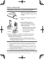
PREPARATION
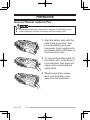
Installing/ Removing the Battery Pack
◆ Do not short the battery terminals or dispose of the battery by fire.
◆ Never attempt to remove the casing from the battery pack.
1 Align the battery pack with the
back of the transceiver, then
press the battery pack and
transceiver firmly together until
the release latch on the base of
the transceiver locks.
2 To remove the battery pack, lift
the safety catch on the base of
the transceiver, then press the
release latch underneath the
safety catch.
3 While pressing the release
latch, pull the battery pack
away from the transceiver.
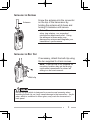
Installing the Antenna
Antenna
Screw the antenna into the connector
on the top of the transceiver by
holding the antenna at its base and
turning it clockwise until secure.
Note: The antenna is neither a handle,
a key ring retainer, nor a speaker/
microphone attachment point. Using
the antenna in these ways may
damage the antenna and degrade your
transceiver’s performance.
Installing the Belt Clip
If necessary, attach the belt clip using
the two supplied 3 x 8 mm screws.
Note: If the belt clip is not installed, its
mounting location may get hot during
continuous transmission or when left
sitting in a hot environment.
Belt clip
Do not use glue which is designed to prevent screw loosening when
installing the belt clip, as it may cause damage to the transceiver. Acrylic
ester, which is contained in these glues, may crack the transceiver’s
back panel.
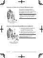
Installing the Cover over the Speaker/ Microphone Jacks
If you are not using a speaker/
microphone, install the cover over
the speaker/ microphone jacks using
the supplied 3 x 6 mm screw.
Note: To keep the transceiver water
resistant, you must cover the speaker/
microphone jacks with the supplied
cover.
Speaker/ microphone
jack cover
Installing the Optional Speaker/ Microphone (or Headset)
1 Insert the speaker/ microphone
(or headset) plugs into the
speaker/ microphone jacks.
2 Attach the locking bracket using
the supplied 3 x 6 mm screw.
Note: The transceiver is not fully
water resistant while using the
speaker/ microphone.
Speaker/ microphone
locking bracket
Charging the Battery Pack
ATTENTION: Always switch OFF a transceiver equipped with a
battery pack before inserting the transceiver into the charger.
1 Plug the AC adapter cable into
the jack located on the rear of the
charger.
2 Plug the AC adapter into an AC
outlet.
3 Slide a battery pack or a
transceiver equipped with a
battery pack into the charging
slot of the charger.
Charging slot
Indicator
• Make sure the metal contacts of
the battery pack mate securely
with the charger terminals.
• The indicator lights red and
charging begins.
4 When charging is completed, the indicator lights green.
Remove the battery pack or the transceiver from the
charging slot of the charger.
• It takes approximately 3 hours to charge the battery pack.
• When the charger will not be used for a long time, unplug the
AC adapter from the AC outlet.
Note:
◆ When the indicator blinks red, the battery pack is either defective or
the battery pack contacts are not properly mated with those of the
charger.
◆ The ambient temperature should be between 41°F and 104°F (5°C
and 40°C) while charging is in progress. Charging outside this range
may not fully charge the battery.
◆ The battery pack life is over when its operating time decreases even
though it is fully and correctly charged. Replace the battery pack.
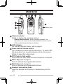
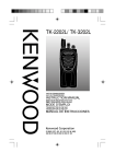
ORIENTATION
Antenna
Battery pack
Channel selector
Rotate to change the operating channel.
• Channel Annunciation: When changing channels, the
transceiver will announce the newly selected channel number.
(This can be deactivated by your dealer.)
LED indicator
For the LED indicator status, refer to page 9.
Power switch/ Volume control
Turn clockwise to switch ON the transceiver. To switch OFF
the transceiver, turn counterclockwise until a click sounds.
Rotate to adjust the volume level.
PTT (Push to Talk) switch
Press and hold, then speak into the microphone to transmit.
Side 1 key {refer to page 7}
Press to activate its programmable function.
Side 2 key {refer to page 7}
Press to activate its programmable function.
Speaker/ microphone jacks
Insert the Speaker/ microphone or Headset plug into this
jack.
PROGRAMMABLE AUXILIARY FUNCTIONS
Your dealer can program the Side 1 and Side 2 keys each with
one of the following functions.
■ None
No function has been programmed.
■ Autodial
DTMF Autodial allows you to make a private call to another
party.
■ Key Lock
Press and hold this key for 1 second to lock/ unlock the
transceiver keys.
■ Key Lock with Status Memory
This operates the same as Key Lock except that when the
transceiver power is turned OFF and then ON again, the
keys remain locked. Without Status Memory, when the
transceiver power is turned OFF and then ON again, the
Key Lock function will be cancelled.
■ Monitor
Momentarily press this key to deactivate signaling (QT/DQT,
FleetSync signaling, etc.). Press the key again to return to
normal operation.
■ Monitor Momentary
Press and hold this key to deactivate signaling (QT/DQT,
FleetSync signaling, etc.). Release the key to return to
normal operation.
■ Scan
Press this key to start scanning the transceiver channels.
■ Scan + Temporary Delete
Press this key to start scanning the transceiver channels.
When Scan pauses at an undesired channel, you can
remove that channel from the scanning sequence by
pressing and holding this key for 3 seconds.
■ Scrambler
The Scrambler function allows you to hold a conversation in
complete privacy. When activated, any other party listening
in on your channel will be unable to understand your
conversation.
■ Squelch Off
Momentarily press this key to hear background noise. Press
the key again to return to normal operation.
■ Squelch Off Momentary
Press and hold this key to hear background noise. Release
the key to return to normal operation.
■ Talk Around
The Talk Around function allows you to communicate
directly with other transceivers, without the use of a
repeater.
■ Temporary Delete
When Scan pauses at an undesired channel, you can
remove that channel from the scanning sequence by
pressing and holding this key for 1 second.
■ Low Transmit Power
Each channel is programmed with either high or low transmit
power. On high transmit power channels, press this key to
change the transmit power to low power (you cannot change
low transmit power channels to use high power).
BASIC OPERATIONS
1 Turn the Power switch/ Volume control clockwise to switch
the transceiver power ON.
• A beep sounds if enabled by your dealer.
2 Press the key programmed with the Monitor or Squelch Off
function to hear background noise, then rotate the Power
switch/ Volume control to adjust the volume.
3 Rotate the Channel selector to select your desired channel.
• When you receive an appropriate signal, you will hear audio
from the speaker.
4 To make a call, press and hold the PTT switch, then speak
into the microphone using your normal speaking voice.
• Hold the microphone approximately 1.5 inches (3 to 4 cm) from
your lips.
5 Release the PTT switch to receive.
Note: When the battery pack voltage becomes too low, transmission
will stop and an alert tone will sound.
LED Indicator Status
Indicator Color
Meaning
Lights red
Transmitting
Lights green
Receiving a call
Blinks red
Battery power is low while transmitting
Blinks green
Scanning
Blinks orange
Receiving an encoded call (QT/DQT,
FleetSync signaling, etc.)
Blinks red/orange
The selected channel has not been
programmed and cannot be used.
VOICE OPERATED TRANSMISSION (VOX)
VOX operation allows you to transmit hands-free. This feature
must first be activated by your dealer, and can only be used if
you are using a supported headset.
To activate VOX and set the VOX Gain level, perform the
following steps:
1 Connect the headset to the transceiver .
• The VOX function does not activate when a headset is not
connected to the accessory terminal of the transceiver.
2 With the transceiver power OFF, press and hold the Side 1
key while turning the transceiver power ON.
3 Continue to hold the Side 1 key until a beep sounds.
• The LED indicator lights orange.
• When the Side 1 key is released, the transceiver announces the
VOX Gain level.
4 Press the Side 1 key to increase the VOX Gain level and
the Side 2 key to decrease the level.
• The VOX Gain can be adjusted from levels 1 to 10 and OFF.
• The transceiver announces the VOX Gain level as you adjust it.
If OFF is selected, a beep sounds.
5 Press the PTT switch to save the setting.
• A beep will sound.
• The transceiver announces the new VOX Gain level.
6 Turn the transceiver power OFF and the ON again to
activate VOX.
Note: If a headset is connected to the transceiver while the VOX
function is switched ON and the VOX Gain level is configured to a
higher, more sensitive level, louder received signals may cause the
transceiver to start transmission.
10
BACKGROUND OPERATIONS
Time-Out Timer (TOT)
The Time-out Timer prevents callers from using a channel
for an extended duration. If you continuously transmit for the
duration programmed by your dealer (default is 1 minute),
transmission will stop and an alert tone will sound. To stop the
tone, release the PTT switch.
Battery Saver
When activated by your dealer, the Battery Saver function
decreases the amount of power used after no signal is present
and no operations are being performed for 5 seconds. When a
signal is received or an operation is performed, Battery Saver
turns off.
Note: While the Battery Saver is operating, the LED may flash
green when receiving a QT/DQT signal which does not match the
QT/DQT tone/code set up in your transceiver.
Low Battery Warning
While operating the transceiver, the Low Battery Warning
sounds an alert tone every 30 seconds and the LED indicator
blinks red when the battery needs recharged or replaced.
Busy Channel Lockout (BCL)
When activated, BCL prevents you from interfering on a
channel that is already in use. Pressing the PTT switch will
cause an alert tone to sound and the transceiver will not
transmit. Release the PTT switch to stop the tone.
Note: Ask your dealer for an explanation on how BCL functions
when using QT, DQT, DTMF, or FleetSync signaling.
11
Signaling
■ QT/ DQT/ DTMF
The Encoder/Decoder function uses QT/ DQT to segregate
talk groups, so users only hear calls from their own group.
A DTMF PTT ID is included for dispatch operations or
simple remote control applications.
The DTMF decode capabilities include Selective Call ID,
Transpond with ID, and “Wild Card” Group Calling.
■ FleetSync
Utilizing Kenwood’s FleetSync digital signaling protocol, this
transceiver has PTT ID and Selective Calling capabilities for
managed dispatch operations.
Beginning/ End of Transmission Signal
The Beginning/ End of Transmission identification signals are
used to access some repeaters and telephone systems. The
Beginning of Transmission ID signal is transmitted when you
press the PTT switch and the End of Transmission ID signal is
transmitted when you release the PTT switch.
12