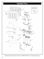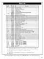
1
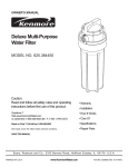
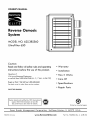
OWNER'S MANUAL
O
O
D
o
Reverse Osmosis
_m
_o
System
MODEL
NO. 625.385560
UltraFilter
_m
650
O
Caution:
Read and follow all safety rules and operating
• Warranty
instructions before first use of this product.
• Installation
Questions
• How It Works
?
Visit www.KenmoreWater.com
or call toll free 1-800-426-9345
(M - F, 7 AM - 6 PM CST)
Repair or Parts ? Call toll free 1-800-469-4663
See back
cover for other Sears service
• Care Of
• Specifications
numbers.
• Repair Parts
SAVE THIS MANUAL
®
System tested and certified by NSF International
against NSF/ANSI
Standard 42 and 58.
See performance
data sheet for details.
Printed on recycled
Sears
PRINTED IN U.S.A.
Brands
Management
Corporation,
Hoffman
www.KenmoreWaler.com
Estates,
IL
60179
Part No. 7322306
paper
U.S.A.
(Rev. A 6/28/10)
ONE YEAR FULL WARRANTY
When installed,
operated
and maintained
according
ON REVERSE OSMOSIS
to all instructions supplied
Reverse Osmosis System fails due to a defect in material
purchase,
call 1-800-4-MY-HOME
to arrange
or workmanship
SYSTEM
with the product, if this
within one year from the date of
for free repair (or replacement
if repair proves impossible).
This warranty does not include filter cartridges or the Reverse Osmosis membrane, which are expendable
items.
This warranty
applies only while this product is in use in the United States or Canada.
This warranty
gives you specific legal rights, and you may have other rights which vary from state to state.
Sears Brands Management
Corporation,
Hoffman
Estates, IL 60179
o
Z
0
13"
Questions?
Call The I<enmore
-_
Water
5-1/2"
Line 1-800-426-9345
or visit I<enmoreWater.com
Unpack
and Check Shipment
......................................................................
4
What Your Reverse Osmosis System Will do ...........................................................
Plan Your Installation
...........................................................................
Overview
and Site Preparation
Step I-Install
Supply
Water
5
5-6
.....................................................................
Fitting
7
..................................................................
Step 2-Install
Reverse Osmosis Drain
Step 3-Install
Reverse Osmosis
Step 4-Install
Storage
Step 5-Install
Reverse Osmosis
8
..............................................................
Filter Assembly
9-10
.........................................................
11
Tank ........................................................................
11
Faucet .............................................................
Step 6-Connect
Tubes
Step 7-Sanitize,
Pressure Test, Purge System
12-13
.........................................................................
14-15
........................................................
16-17
How Your Reverse Osmosis Water System Works ....................................................
Maintenance
................................................................................
Specifications
..................................................................................
Troubleshooting
Exploded
•
22
.............................................................................
24-25
View & Parts List ....................................................................
26-27
Read all steps and guides carefully before installing
and using your reverse osmosis system. Follow all steps
This system is acceptable
for treatment of influent concentrations of no more than 27 mg/L nitrate and 3
exactly
mg/L
nitrite
tified
for nitrate/nitrite
to correctly
install.
Reading
this manual
also help you to get all the benefits from
will
the reverse
osmosis system.
•
Do not attempt to use this product
ing water from non-potable
water
of unknown quality
before
without
to make safe drinksources. Do not use
unsafe water,
adequate
and may be used on disinfected
that may contain
filterable
•
or water
measured
reduction
as N and is cer-
only for water
sup-
The reverse osmosis system works on water pressures of
40 psi (minimum) to 100 psi (maximum). If your house
water
disinfection
pressure is over the maximum,
reducing
or after the system. This system is certified
cyst reduction
in combination
plies with a pressure of 280 kPa (40 psig) or greater.
the system on microbiologically
•
18-19
20-21
for
valve in the water
install a pressure
supply pipe to the reverse
osmosis system.
water
Do not install the reverse osmosis system outside, or in
extreme hot or cold temperatures.
Temperature
of the
cysts.
water supply to the reverse osmosis system must be
between 40°F and IO0°F. Do not install on hot water.
Check with your local public works department
for
plumbing and sanitation codes. You must follow their
guides as you install the system. Follow your local
codes if they differ
•
with guides in this manual.
This system shall only be used for arsenic reduction on
chlorinated
water supplies containing detectable
residual free chlorine
at the system inlet. Water
using an inline chlorinator
chlorine
contact
Questions?
should provide
time before
systems
a one minute
•
Read the other limits (pH, hardness, etc.) in the specifications and be sure your water supply conforms.
•
The reverse
osmosis
for
and
storage
ed on
page
membrane
shipment.
17 before
using
contains
a preservative
Be sure to
purge
product
water.
as instruct-
the RO system.
Call The Kenmore
Water
Line 1-800-426-9345
or visit KenmoreWater.com
3
INSPECT
SHIPMENT
Your Reverse Osmosis
complete
Drinking Water
in one carton.
System is shipped
Remove all items from
your ship-
ping carton.
Check all items against
the packing
items lost or damaged
the shipping
carton.
in shipment.
for the part
numbers of missing or damaged
plumber
names and
exist,
listed through-
bag until you are ready
NOTE: Codes in the state of Massachusetts
lation by a licensed
saddle valves.
to
view and parts
items. If problems
or the toll free number
Keep the small parts in the parts
to install them.
Note any
Note any damage
Refer to the exploded
list in the back of the manual
refer to the website
out this manual.
list below.
require
instal-
and do not permit the use of
If you live in the state of Massachusetts,
review plumbing
code 248-CMR of the Commonwealth
of Massachusetts
before
proceeding
with the installation.
Bag Assembly
Bag Assembly
_q
©
Reverse Osmosis
Assembly
Water
Storage
Tank
Drain Adaptor Kit
Bag Assembly
/
Dropper
Thread Sealing Tape
Tee, Feed
Adapter
Tank
Connector
Nitrate/Nitrate
Questions?
4
Call The Kenmore
Water
Line 1-800-426-9345
Test kit
Reverse Osmosis
Faucet
Assembly
or visit KenmoreWater.com
Your Reverse Osmosis
treatment
natural
physical
is forced
process
through
and impurities
faucet
with
are filtered
while
RO waste
measured
in water
ticles,
cartridges.
other
before
osmosis.
Water,
minerals
it can enter
any tastes and/or
dissolved
solids
reduces
and chlorine
that
through
minerals
goes to the
are sent to the
the RO membrane,
To prevent
closes when the RO faucet
Your reverse
sparkling
osmosis
clear,
RO product
(TDS).
sediment-
is closed
water
look and taste
water
and just before
waste, an automatic
going
shutoff
and the storage
system gives you a continuous
delicious
uses. Foods will
are
water
for drinking,
better
at your fingertips
bottled
water.
The storage
product
water
for your needs.
tank
tank is full.
supply
cooking
too. Having
eliminates
to the
valve
of
and other
high quality
the need to buy
holds over 2 gallons
of RO
sand, silt, dirt, rust par-
from
the RO membrane.
odors
pressure,
and impurities
passing
RO faucet.
under
water
impurities
a
where
pre and postfilter
The prefilter
sediments,
drinking
and
replaceable
to reverse
membrane
The minerals
as total
System is a water
pressure
out. Clean
water.
The system includes
carbon
called
Water
water
a semi-permeable
or storage,
drain
(RO) Drinking
unit. It uses household
the water
supply
The postfilter
may remain
reduces
in the water,
after
PLAN YOUR INSTALLATION
It is recommended
before
beginning
ly. Reading
to read through
your installation.
this manual
the entire manual
Tools Needed
Follow all steps exact-
will also help you get all the ben-
efits from your system.
Your Reverse Osmosis
installed
remote
Drinking
Water
under a sink or in a remote
sites are a laundry
the location
options
below
System can be
location.
Typical
room or utility
room. Review
and determine
where
Adjustable
you are
Wrench
going to install your system.
NOTE:
For best system performance,
the feed water
to
the system should be softened or less than 10 grains per
gallon hard.
UNDER
THE SINK
LOCATION
Phillips
The Reverse Osmosis Filter Assembly
normally
installed
in a kitchen
and storage
or bathroom
Screwdriver
Tape
tank are
Measure
sink cabinet.
See Figure 2.
A suitable drain point is needed
Reverse Osmosis filter.
REMOTE
for reject water
S
from the
LOCATION
You can also locate the Reverse Osmosis
and storage
tank in a remote
location
Filter Assembly
away
from
Reverse Osmosis
Faucet. You will need a nearby
source and drain
point.
the
Drill & Drill
Flathead
bits, if required
Screwdriver
water
See Figure 3.
CHECK
SPACE REQUIREMENTS
Check size and position
into location chosen.
TOOLS
of items for proper
Large
Adjustable
Jaw Pliers or Pipe Wrench
NEEDED
Review the tools needed
tools before
follow
installation
proceeding
the instructions
Questions?
list. See Figure 1. Gather
with the installation.
provided
Call
The
needed
Read and
Figure
with any tools listed here.
Kenmore
Water
Line 1-800-426-9345
or visit
KenmoreWater.com
5
Typical Under Sink Installation
All install parts included in package.
Drain Adapter
for Reverse
Osmosis
Waste
Water
Reverse
Osmosis
Assembly
Figure 2
Typical Remote Installation
Outside
(Hard
Faucet
Water)
Outside
(Hard
Soft,
Cold
To
Faucet
Water)
Water
Reverse
Osmosis
Air Gap
Faucet
Soft, Hot
Soft, Cold
Water
Sediment
Filter_
Reverse
Osmosis
System
Storage
Tank
Water
Meter
Water
Softener
Additional
Main
Air Gap
Shutoff
It
Valve
Parts required.
Figure 3
Questions?
6
Call
The
Kenmore
Water
Line 1-800-426-9345
or visit
KenmoreWater.com
OVERVIEW
There are seven easy steps to installing
Water
your Drinking
system. They are as follows=
STEP 1 - Install
Cold Water
Supply
fitting
STEP 2 - Install Drain Adapter
STEP 3 - Install
Reverse Osmosis Assembly
STEP 4 - Install Storage
Tank
STEP 5 - Install Reverse Osmosis Faucet
STEP 6 - Connect
Tubing
STEP 7 - Sanitize,
Pressure Test, Purge System
These steps are explained
in detail
over the next few
to read through
the entire manual
pages.
It is recommended
before
beginning
ly. Reading
your installation.
this manual
all the benefits
Figure
4
Follow all steps exact-
will also help you receive
and use
your Reverse Osmosis System can give
yOU.
PREPARE SITE FOR INSTALLATION
1. Before starting,
valves
close the hot and cold water
shutoff
(See Figure 5).
2. Temporarily
net. Double
place tank and filter assembly
check position
into cabi-
of items and space required
for proper installation.
3. Remove tank and filter from cabinet
NOTE: You must check and comply
and set aside.
with all local plumb-
ing codes.
Questions?
Call
The
Kenmore
Water
Line 1-800-426-934.5
or visit
KenmoreWater.com
7
CHOOSE TYPE OF WATER FITTING TO INSTALL
Check and comply
with local plumbing
plan, then install a cold feed (supply)
to the Specifications
The fitting
1/4"
page
must provide
tubing.
A typical
supply fitting
codes as you
water
fitting.
for supply water
a leak-tight
connection
requirements.
connection
to the RO
using the included
is shown in Figure 5.. An optional
using standard
plumbing
Refer
fittings
water
connection
(not included)
is shown in
Figure 5B.
NOTE:
Local code may dictate
which type of water
ting is used. Consult a plumber
with local codes or plumbing
If you live
,.
procedures.
plumber
Massachusetts
Valve
Shutoff
Valve
_1
I
water
supply
fitting
require
review
of the Commonwealth
before proceeding
.
and do not permit the
in the state of Massachusetts,
ing code 248-CMR
Shutoff
if you are not familiar
NOTE: Codes in the state of Massachusetts
installation by a licensed
use of saddle valves.
fit-
plumb-
faucet
c°la water
stud /
thread sealing
tape on threads
•_J _
(tee, feed
adaptor)
7__
of
with the installation.
pipe
cold water
.
Reverse
Osmosis
_i/4"
green
tubing inlet
to
_
INSTALL COLD WATER SUPPLY FITTING
(Included with your package)
This fitting
fitting
Cold Water
will be installed on the cold water
must provide
Osmosis 1/4"
a leak-tight
tubing.
connection
Complete
the following
(using included water
supply fitting)
Figure 5
to the Reverse
Locate the cold water
sink cabinet. It is recommended,
cold water line be soft water.
pipe. The
Supply Connection
line in the
but not required,
steps to install the water
that the
supply
fitting.
1. Close the water
before
shut off valve that is immediately
supply fitting
and open faucets
to drain
from the sink cold water pipe.
2. Remove nut that connects the cold water
water
water
faucet
to cold
plumbing.
3. Thread
water
nut to bottom
OPTIONAL
supply fitting
onto pipe and reconnect
Hot Water
Shutoff
Valve
of fitting.
Cold
m
I
1/4"
PIPE FITTINGS
j
(compression type shown)
NOTE:
supply and open a
faucet to drain the pipe.
with plumbing
cold water
nection
pipe to adapt
codes, install
1/4"
ing tape
OD tubing.
compound
on the
A typical
fittings
fitting
f
ferrule
Call The Kenmore
1/4"
pipe
conseal-
Cold Water
Supply Connection
(using compression
Water
green
tubing to Reverse
Osmosis inlet
are
or thread
on outside threads.
Questions?
compression
cold water
a fitting
is shown in Figure 5B. If threaded
used, be sure to use pipe joint
Valve
insert
Be sure to turn off the water
Complying
Water
Shutoff
Line 1-800-426-9345
fitting - not included)
Figure 5B
or visit KenmoreWater.com
Under The Sink Installation
INTRODUCTION
A suitable
drain
point is needed
for the reject water
the Reverse Osmosis Filter. You have two options
choose from:
• Install
the Drain Adapter
from
to
Single trap
J
included with your unit
See Figures 6, 7 & 8. This is used in under the sink
installations. The drain adapter kit is installed onto
your sink drain
Double Trap
pipe above
Drain
!_
the P-trap. See Figure 6.
Adapter
• Use another existing drain in your home
This is usually used in remote location type installations. The drain tube from the Reverse Osmosis Filter
runs directly
to an open drain.
See Figures 9 & 10.
P-Trap
__
P-Trap
NOTE: Local code may dictate which type of drain installation is used. Other than local code, either drain installation types may be used. Consult a plumber
familiar with plumbing procedures.
INSTALL
(Under
DRAIN
ADAPTER
if you are not
Figure 6
KIT
sink Installation)
In an under the sink installation,
you normally
use the
i0:00,,,
P-trap drain adapter. A drain adapter kit is included in
your package. Review the drain adapter kit parts in
Figure 8. The drain adapter is always installed in the sink
drain pipe, above or ahead of the P- trap. See Figures 6
& 8. Be sure to comply with your local plumbing codes.
The drain
adapter
fits 1-1/2" sink drain
pipe fittings, purchased
tion to the adapter.
locally,
pipes. Other
may be needed
Ngr_
Ferrule
z2:00
Sink Tailpiece
O
Drain Adapter
drain
FerruLe
in addi-
1. Slowly disassemble the sink drain pipe between the sink
P-trap and the sink tailpiece.
See Figures 6 & 8.
2. Clean the sink tailpiece to assure a leak-tight
fit.
3. Install drain adapter directly onto the sink tailpiece
Nut
Cut, if
needed
Drain Tubing
Connector
Figure
7
using the ferrule and nut. Snug the nut, but do not tighten. See Figure 7.
4. Assemble the drain tubing connector to the drain
adapter using the ferrule and nut. Snug the nut, but do
not tighten. See Figure 7.
NOTE:
Locate so drain tubing
from the Reverse
Osmosis faucet will make a straight run to the adapter,
without dips, loops, low spots or kinks. See Figure 8.
5. Turn the connector to about 45 ° (10:00 or 2:00 posi-
i_J
J_B_bCk
Drain
tion). See Figure 7. Tighten the nut securely.
[-_
6. Assemble the P-trap to the drain adapter, and other
drain pipe fittings as required to complete the drain
run. See Figure 6.
NOTE: If needed, you can cut the unthreaded
end of
the adapter to make it fit. Do not cut too short or the
adapter will not make a leak-tight
necting fitting.
7. Tighten all connections,
connections.
Questions?
seal with the con-
but do not over tighten
Call The Kenmore
Water
plastic
n_
L----_HC_T
__"_
C_O
LD _.._......_
Drain Adapter"
p_Trap
IMPORTANT:Locatedrain adapter so when the black drain tube
from the ReverseOsmosisFaucet is installedlater on, it
will make a straightrun to the adapter, without dips,
loops,low spotsor kinks.
Figure 8
Line 1-800-426-9345
or visit KenmoreWater.com
9
Outside
(Hard
Faucet
Outside Faucet
Water)
BLUE Tubing
to Reverse
Osmosis Air
(Hard Water)
Soft, Cold
Water
Gap Faucet
Soft, Hat Water
Line
Soft, Cold
GREEN
Tubing to Reverse
Osmosis System
Remote
Location
Sediment
Filter
Reverse
Installation
Osmosis
YELLOW
Tubing
to TankStorage
i
Storage
Tank
Water Meter
Water
Heater
Main
Shutoff
Valve
c_
Sump
Figure 9
[_ Air_ap
W2"
Floor
Stand pipe
INSTALL
Laundry Tub
Airgap
A REMOTE
DRAIN
POINT
AND
Drain
AIR
GAP
(Remote Location)
You can also run the drain tubing
the house. A floor
etc. are suitable
drain
drain, laundry
drain
is the preferred
Always
drain
in
sump,
points. See Figure 10. This type of
over the p- trap
Check your local codes.
parts list in back
to an existing
tub, standpipe,
of manual)
be sure to provide
the hose and the drain
drain
Longer lengths
adapter.
of tubing
(see
may be needed.
an air gap between
point. This will prevent
backing up into the system. Airgaps
most areas.
the end of
water
are required
from
code in
Figure 10
To install a remote drain point, complete
the following
steps:
1. Locate the 1/4" red tubing on the Reverse Osmosis filter assembly. See Figure 9.
2. Determine if this length
drain point.
is long enough
to reach the
3. If not, disconnect the 1/4" red tubing and replace with
an adequate length of tubing to reach the drain point.
Refer to Step 6 later in the manual on how to disconnect and connect tubing.
NOTE: A flow control insert is located in the red tube.
Refer to Key No. 14 on Page 26. This insert must be
saved and placed
in the new length of tubing.
4. Run the tubing to the drain point and secure at the end
with a bracket (purchased locally). See Figure 10.
Provide a 1-1/2" air gap between the end of the tube
and the drain.
Questions?
10
Call
The
I<enmore
Water
Line 1-800-426-9345
See Figure 10.
or visit
KenmoreWater.com
INSTALLREVERSE
OSMOSISFILTER
ASSEMBLY
The Reverse Osmosis Filter Assembly
on its side. When
planning
allow
adequate
back
of the Reverse Osmosis assembly
the monitor
tubing
battery.
can sit upright
your installation,
or lay
you need to
lengths to be able to access the
in order to change
See Figure 11.
Figure 11
INSTALL STORAGE TANK
Jr
Jj
1. Apply
thread
sealing
tape to the threads
at the top of the tank (max.
2. Locate the tubing
tor with a wrench
connector.
2 wraps).
Tighten
//
on the nipple
/
the tubing
/
//
See Figure 12.
connec-
onto the tank nipple 7-8 turns, being
tank
nipple
_/tubing
connector
careful not to cross thread or overtighten.
See Figure 12
3. Do not connect the tube at this time. This will occur
later in the assembly.
4. Place the storage
Assembly.
side.
tank next to the Reverse Osmosis
The tank can be placed
upright
or on its
ge tank
Figure 12
Questions?
Call The Kenmore
Water
Line 1-800-426-9345
or visit KenmoreWater.com
11
SELECT LOCATION
MOUNTING
OF REVERSE
OSMOSIS
FAUCET
HOLE
faucet
You will need to select the location
of the Reverse
Osmosis Faucet. You have three options
° Use the existing
to choose from:
sink top hole for the spray
soap dispenser (Must be 1-1/4"
° Drill a new hole in the sink
hose or
in diameter)
° Drill a new hole in the countertop
next to the sink
1. Determine where you are going to install your Reverse
Osmosis Faucet.
2. Check to ensure the Reverse Osmosis faucet
flat against
3. Visually
the mounting
review the routing
Reverse Osmosis filter
4. If drilling
and filter
to the faucet.
tube routing
screw
i
u/faucet
__
base
drill a 1-1/4"
diameter
hole in the
___
rubber
washer
surface.
IMPORTANT:
Drilling
holes into countertops
should only be performed
by a qualified
is certified for drilling such materials.
faces made of stone or solid surface
granite,
Check to
space between
assembly.
is needed,
mounting
faucet
1/4 turnbase
to connect
of the tubes from the
assembly
ensure there is adequate
the faucet
will mount
surface.
marble,
Corian
or sinks made of porcelain
cause permanent,
countertop
installer
resin products
and stainless steel may
irreparable
damage
toggle
bolt_
who
Drilling of surmaterials such as
or other plastic
TM
and sinks
to the sink or
surface.
_
4__-____
_
_
_n°nmnaenCftc_d
etectr°nics
hole in sinkor
3,8,,
countertop
3/8" BLUEtubing_
/
,
F:qJ_f:_
/
_
_.
\
Figure 13
INSTALL REVERSE OSMOSIS FAUCET
1. Locate and organize
to Figure 13.
2. Mount faucet
your RO faucet
install parts. Refer
base to sink hole until the faucet
base is
square against the sink surface. The rubber washer
should be between the sink surface and the faucet
base.
3. Tighten
the toggle
bolts until the base is firmly
to the sink surface.
4. Feed a length
and connect
bottom
to the 3/8"
of the faucet.
up through
quick connect
the hole
fitting
on the
See Figure 14.
of 1/4"
and connect
to the 1/4"
faucet.
red tubing
up through
barb on the bottom
the hole
of the
See Figure 14.
the length
of 3/8"
barb on the bottom
Questions?
12
blue tubing
5. Feed a length
6. Connect
mounted
Do not overtighten.
of 3/8"
Call
black
of the faucet.
The
tubing
to the 3/8"
See Figure 14.
Kenmore
tu ,n
Water
Line 1-800-426-9345
or visit
KenmoreWater.com
NOTE:
If you ran the red reverse osmosis drain tubing
directly
to a remote
drain
and refer to instructions
7. Mount
the faucet
point, disregard
on page
body
steps 5 and 6
10.
on to the faucet
base, 1/4 turn.
jJ
BLACK TUBE
FAUCET ELECTRONICS
The RO system will monitor
the total product
the unit and also length of time the filters
installed.
The faucet
flashes to inform
3/8" barb fitting
for the black tube
flow of
have been
base has an indicator
light that
TUBE
you of the status of the RO membrane
BLUE TUBE
3/8" quick connect
fitting for the blue tube
and filters.
Green
- RO membrane
Amber
- Warning,
replacing,
and filters
filters
when water
1/4" barb fitting
for the red tube
are good.
need replacing.
has been drawn,
Filters need
Figure 14
after 6 months
time (or 650 gallons
have been used).
Red - RO membrane
needs to be replaced.
INSTALL BATTERY
When
the coin battery
the LED indicator
sequence.
is first applied
at initial
start up,
light will flash in a red, amber,
All timers
green
and counters are reset to zero. In
order to reset the time and gallon count feature, push the
the button on the PWA and hold until the LED flashes and
release.
filter
The battery
replacement.
equivalent).
Improper
age electronics.
align
needs to be replaced
Use only lithium
placement
of battery
it correctly on PWA with the proper
board
Reset button
at the time of
batteries
Use care when inserting
PWA
(CR 2032
or
Battery
J
could dam-
the battery
to
polarity.
See
Figure 15.
Figure 15
Questions?
Call The Kenmore
Water
Line 1-800-426-9345
or visit KenmoreWater.com
13
HOW
TO CUT AND
CONNECT
Your Reverse Osmosis Water
tings for quick tubing
instructions
before
THE TUBES
System includes push-in fit-
connection.
connecting
Review the following
the tubes in the next step.
Cut tubes to length
1. Use a sharp cutter
Always
or knife to cut the end of tubing.
cut the tubing
square.
2. Inspect the end (about
are no nicks, scratches
cut the tubing
NOTE:
1") of the tubing
smooth,
to be sure there
square
with
with
end of tubing
no cuts,
nicks or flat
round,
spots.
Tube Correctly Cut
or other rough spots. If needed,
Figure 16
See Figure 16.
Tubing lengths
the assembly
tubing
again.
Cut tubing
See Figure 16.
should allow for the removal
from the hanger
lengths are shortened
of
washers
for servicing.
If
for neater
appearance,
it
may be necessary to keep the assembly
washers for service.
on the hanger
Caltet
Connect tubes
1. Push tubing
through
collet,
See Figure 17. Continue
out against
the back
common
mistake
engages
the o-ring.
a 1/4"
of the fitting.
the o-ring.
__f
See Figure 18. A
Tube Partially Engaged With Fitting
is to stop pushing when the tube
This will lead to future
tube is fully engaged,
entered
3/4"
&18.
until it engages
pushing until the tube bottoms
the fitting.
When
Figure 17
leaks. When
11/16" of the tube has
a 3/8"
of the tube has entered
tube is fully engaged,
the fitting.
See Figures 17
O-Ring
2. If using tubing
other than tubing
tem, be sure it is of high quality,
ness with a smooth surface.
supplied
with the sys-
exact size and round-
Disconnect Tubes
1. Push the collet
2. Continue
inward
holding
with a finger tip. See Figure 20.
collet inward
while pulling
the tubing
Tube Fully Engaged With Fitting
out. See Figure 20.
Figure 18
Cotlet
(Depress
to
Remove Tubing)
Fitting
O-Ring Seat
Callet
Disconnect Tubing
Collet and O-Ring
Figure 19
Figure 20
Questions?
14
Call The Kenmore
Water
Line 1-800-426-9345
or visit KenmoreWater.com
NOTE:
back
3/8"
black tubing
Tubing
lengths
NOTE:
access to the
for servicing.
Codes in the state of Massachusetts
installation
by a licensed
the use of saddle
211
should allow
of the assembly
plumber
valves.
and
require
do not permit
If you live in the state of
ii
Massachusetts,
red tubing
the Commonwealth
ceeding
blue
water supply
review
plumbing
code 248-CMR
of Massachusetts
before
of
pro-
with the installation.
tubing
fitting
HOT
COLD /
1/4"
green
tubing
3/8"
sink p-trap
_,_
yellow
tubing
tubing
connector
r
UI :
O
Tube Connections
Figure 21
CONNECT
1. Locate
the yellow
Osmosis
filter
2. Run the other
the storage
3. Cut tube
CONNECT BLUETUBE TO REVERSEOSMOSIS ASSEMBLY
YELLOW TUBE TO STORAGE TANK
tube.
One end is attached
to the Reverse
assembly.
tube to the fitting
on top of
See Figure 21.
square
4. Do not connect
and to length.
See Figure
at this time. This will occur
CONNECT
FAUCET
16.
in the sanitizing
step.
was completed
BLACK
TO DRAIN
TUBE
GREEN
in the faucet
TUBE
1. Locate the 30" length
TO
COLD
WATER
SUPPLY
FROM
REVERSE
green tube to the fitting
OSMOSIS
of 3/8"
black
tube.
One end is
to the black
collet
on the water
pipe. See Figure 21.
adapter.
3. Cut this tube as needed
possible,
without
loops,
to route
in as straight
of a run as
dips, low spots or kinks.
2. Cut tube square
and to length.
See Figure 16.
4. Cut the end of the tube square.
See Figure
3. Connect
water
fitting.
5. Insert all the way into the fitting.
See Figures 17 & 18.
CONNECT
supply
See Figure 5.
RED TUBE TO REVERSE OSMOSIS
The red tube connection
was completed
FAUCET
in the faucet
on the
PIPE
sink drain
1. Run one end of the 1/4"
to cold
assembly
ADAPTER
attached
to the faucet. Figure 21.
2. The other end needs to be attached
CONNECT
supply
connection
steps.
end of the yellow
tank.
The blue tube
6. Pull on the tube to be sure it is held firmly
16.
in the fitting.
assembly
steps.
Questions?
Call
The
Kenmore
Water
Line 1-800-426-9345
or visit
KenmoreWater.com
15
SANITIZETHESYSTEM
Sanitizing
is recommended
immediately
after installation
of the Reverse Osmosis system. It's also recommended
after servicing
inner parts. It is important
installing
or servicing
handling
inner parts of the system.
Complete
that the person
the system have clean hands while
the following
steps to sanitize
!
the system.
See Figure 22.
1. Turn off the water
tem.
2. Open
supply to the Reverse Osmosis sys-
the Reverse Osmosis faucet.
already
empty, allow the water
3. Locate the eyedropper
common
household
ing. Handle
bleach
recommendations.
5. Connect
yellow
to empty.
that is included
bleach
4. Add 3 ml. of bleach
If the tank is not
in package
and
(5.25%).
into open end of yellow
according
to bleach
tank tub-
manufacturer's
See Figure 22.
tank tubing
to tank connector.
See
Figures 12 and 22.
6. Sanitizing
the system will be completed
pressure test and purging
NOTE: The bleach
before
drinking
must be removed
the water.
during
steps on the following
the
page.
Figure 22
from the system
See purging
instructions
on the
next page.
Questions?
16
Call The Kenmore
Water
Line 1-800-426-9345
or visit KenmoreWater.com
PRESSURE
TESTTHESYSTEM
NOTE: Complete
the sanitizing
ing page
pressure testing.
before
Reverse
procedures
Osmosis
Faucet
on the precedkitchen
To pressure test the system, complete
1. Open
the water
the following
faucet
_
__
steps.
supply valve to the Reverse Osmosis
System. See Figure 23.
2. Open
the main water
faucets.
supply valve
and several
house
This will purge air from the house plumbing
and system. Close faucets
when water
runs smooth.
See
Figure 23.
3. Pressure will start to build in the RO system in about 2
hours Carefully
system builds
check all fittings
and connections
pressure. Check for water
leaks. Fix leaks
if any are found.
If problems
bleshooting
or call the toll free number.
chart
NOTE: When
"spurt"
exist, refer to the trou-
the system is first pressurized,
from the faucet
as the
water
may
Water
air gap hole until air is expelled
valve
from the RO system.
supply
Osmosis
Please review
using your
fhe following
operating
Reverse Osmosis
You will not have filtered
shutoff
tee, feed
to Reverse
adapter
System
feafures before
Figure 23
Sysfem:
water
immediately.
It may
take 1-3 hours to completely
fill the storage tank and
create maximum flow from the Reverse Osmosis faucet.
NOTE:
Codes in the state of Massachusetts
installation by a licensed
use of saddle valves.
plumber
If you live in the state of Massachusetts,
Water
Pressure from the Reverse Osmosis faucet
less than your standard
Water
water
water,
of water
ple of hours. Water
going
plumb-
of
with the installation.
You may hear
going to the drain
for a cou-
to the drain will automatitank is full.
THE SYSTEM
To purge the system, complete
1. Open
before proceeding
review
even if you are not drawing
shut off when the storage
PURGING
of the Commonwealth
while the Reverse Osmosis
from the Reverse Osmosis faucet.
a small quantity
cally
Massachusetts
faucet.
will run to the drain
system is producing
will be
ing code 248-CMR
require
and do not permit the
the following
steps.
the Reverse Osmosis Faucet and let water
through the system for a 24 hour period.
NOTE: Water flow will be a slow trickle at this time.
2. Close the Reverse Osmosis faucet
purging
3. When
period
after the 24 hour
is complete.
the purging
is finished,
your Reverse Osmosis
system is ready for use.
Questions?
Call
The
Kenmore
Water
Line 1-800-426-9345
or visit
KenmoreWater.com
17
HOW YOUR REVERSE OSMOSIS SYSTEM WORKS
Introduction:
Your Reverse Osmosis (RO) Drinking
System uses your household
through
three filters.
out. Delicious
tank-ready
tasting
water
Minerals
and impurities
drinking
water
for your use. Minerals
clown the drain. The following
Prefilter:
Water
paragraphs
Water
in
System
from the cold supply pipe enters the pre-
ment cartridge
sediments,
are sent
will explain
Drinking
filter. See Figure 24. The prefilter
The cartridge
are filtered
goes to the storage
and impurities
detail how your Reverse Osmosis
works.
Water
pressure to force water
with activated
is a replaceable
carbon
sedi-
in its composition.
and up to the amount
of chlorine
Reverse
Osmosis Cartridge:
prefilter,
to the Reverse Osmosis membrane
Filtered
water
Figure 24. The Reverse Osmosis cartridge
special
membrane.
The membrane
solved solids and organic
water
(about
one ounce
Osmosis cartridge.
tank, postfilter
Reject water,
matter.
shown in the
cartridge.
See
Faucet:
The sink or countertop
knob to access drinking
Figure 24. An air-gap
is built into the faucet
connection
24.
with plumbing
to comply
faucet
water.
drain
See
water
codes. See Figure
Faucet Electronics: The RO system will monitor
the total
product flow of the unit and also length of time the filters
have been installed. The faucet base has an indicator
light that flashes to inform
membrane and filters.
Green
- RO membrane
Amber
- Warning,
you of the status of the RO
and filters are good.
Figure 24. A diaphragm
Red - RO membrane
needs to be replaced.
solids and organic
Assembly:
to capacity,
See Figure 24.
matter,
tank holds product
water.
See
pres-
The unit has an automatic
water.
When
the storage
and the drinking
water
shutoff
sys-
tank has filled
faucet
is closed, pres-
sure closes the shutoff
to stop flow to the drain. After
enough
is used, pressure in the system
drinking
water
drops, and the shutoff
refilled.
the tank to be
A check valve is located
Osmosis manifold,
valve
opens to allow
See Figure 24.
Check Valve:
inside the tank holds water
after 6 months
have been used).
reduces the dis-
flows to the storage
Filters need
has been drawn,
time (or 650 gallons
tem to conserve
product
filters need replacing.
when water
Shutoff
See Figure 24.
Storage Tank: The storage
replacing,
is a tightly
exits the Reverse
water
or Reverse Osmosis faucet.
with the dissolved
flows from the
High quality
per minute)
The product
is routed to the drain.
prevents
above
in the Reverse
the center sump. The check
a backward
flow of product
from
surized to about 30 psi when the tank is full. This provides
fast flow to the Reverse Osmosis faucet. When the tank is
empty
Flow Control: Water flow to the drain is restricted by the
flow control. It maintains the desired flow rate to obtain
of water,
product
Before going
water
The postfilter
remaining
it is pressurized
to 5 - 7 psi.
to the Reverse Osmosis faucet,
goes through
the postfilter.
is an activated
carbon
Questions?
Call
drinking
The
water
Kenmore
from the product
is available
Water
age the Reverse Osmosis Membrane.
the highest quality
located
type filter. Any
tastes and odors are reduced
water. Clean, high quality
the faucet.
See Figure 24.
tank to drain. A backward
water
the storage
Postfilter:
18
Osmosis
has a hand operated
reduces taste, odor, sand, silt, dirt, other
specifications.
wound
Reverse
drinking
water.
in the end of the 1/4"
Reverse Osmosis manifold
drain
flow could damSee Figure 24.
The flow control
red drain
port. See Figure 24.
at
Line 1-800-426-9345
or visit
is
tubing, at the
KenmoreWater.com
PRODUCT
WATER FAUCET
Fq
air
PRODUCT WATER
dgravity
rain
WASTE
WATER
AUTOMATIC drain flow
SHUTOFF
control
check
valve
\
O
WATER
iN
GREEN
i
BLUE
t_
PREFILTER
POSTFILTER
t t
IL
RED
RO
MEMBRANE
"_
YELLOW
IN
Reverse Osmosis Water Flow Schematic
Figure 24
Water
Flow
Description
1. Water
enters prefilter.
Sand, silt and other sediments
2. Water
leaves prefilter
and proceeds
3. Water
enters the Reverse Osmosis membrane.
4. Processed water
5. Waste
water
are reduced.
is also reduced.
to the Reverse Osmosis Cartridge.
Dissolved
leaves the Reverse Osmosis Membrane
with dissolved
Chlorine
solids are reduced.
and flows to the storage
solids leave the Reverse Osmosis membrane
tank.
and flows to the drain.
6. Faucet is activated.
7. Processed water
8. Water
leaves the storage
tank and flows to the post filter filtered
to ensure fresh taste.
flows to the Reverse Osmosis faucet.
Questions?
Call The Kenmore
Water
Line 1-800-426-9345
or visit KenmoreWater.com
19
PREFILTER/POSTFILTER
MAINTENANCE
Cover
NOTE: It is recommended
to replace the battery, prefilter
and postfilter cartridges at least every 6 months of product water use. Replace
with sediments.
The prefilter
more often
and postfilter
if they begin to plug
are replaceable
sediment
carTurn to the left
tridges with activated carbon in its composition.
See
Figure 25. You must periodically
replace the prefilter and
postfilter
from
cartridge.
This will protect
being destroyed
by chlorine.
to remove
the RO membrane
It will also prevent
filters from plugging with sediments.
You may notice a slower output of product
water
the
Postfilter
as the
Cartridge
prefilter
and postfilter
the prefilter
build
and postfilter
should replace
tridges.
up with sediments.
cartridges
the battery
RO
whenever
you replace
Cartridge
the car-
Prefilter
RO MEMBRANE
CARTRIDGE
The Reverse Osmosis cartridge
membrane.
Replace
when this occurs. You
is a tightly
See Figure 25. The membrane
dissolved solids and organic
Reverse Osmosis membrane
the pH and hardness
Cartridge
MAINTENANCE
wound
Figure 25
special
reduces the
matter. The life of the
cartridge depends mostly on
of the supply water.
(see specifica-
tions). Cartridge
life is shorter with higher pH. For example, if supply water pH is from 6.8 to 7.7, the cartridge
may last for well over one year. However,
cartridge
life
may be as short as 6 months if the pH is as high as 8.5 to
10. Higher pH weakens the cartridge
membrane and
causes pin-hole leaks. It's time to replace the Reverse
Osmosis cartridge
ty of product
when the production
water
drops.
rate and/or
Product water
quali-
may begin to
taste different
or bad, indicating
solids and organics are
passing through the Reverse Osmosis membrane. See
Reverse Osmosis cartridge
replacement.
REVERSE OSOMOSIS
CARTRIDGE REPLACEMENT
PREFILTER/POSTFILTER
Complete
steps to replace
Complete
the following
the cartridges.
1. If possible,turn off the water supply to the RO system.
2. Remove (turn to the left) the pre filter cartridge from
the filter head to relieve
pressure on the Reverse
5. Discard the cartridges
6. Install new cartridges
in a proper
4. Install
manner.
in reverse order (postfilter,
the timer
battery.
5. Remove and replace
to
See Figure 29.
manner.
in reverse order
the timer
(postfilter
battery.
See Figure 29.
6. Turn on the water supply to the RO system.
7. Purge the Reverse Osmosis membrane cartridge.
page
Call The Kenmore
cartridge.
Water
17 for instructions.
See
Line 1-800-426-9345
first,
to the right to re-attach
supply to the RO system.
9. Purge the Reverse Osmosis membrane
page 17 for instructions.
2O
in a proper
new cartridges
then pre filter). Turn cartridges
to the filter heads.
Reverse Osmosis and then prefilter). Turn cartridges
the right to re-attach to the filter heads.
7. Remove and replace
the cartridges.
1. If possible,turn off the water supply to the RO system.
2. Remove the pre filter cartridge
(turn to the left) from
3. Discard the cartridges
3. Remove the Reverse Osmosis cartridge.
4. Remove the postfilter cartridge.
Questions?
steps to replace
REPLACEMENT
the filter head. Then remove the post filter cartridge.
Osmosis cartridge.
8. Turn on the water
the following
CARTRIDGE
or visit KenmoreWater.com
See
CHANGE
COLLET AND O-RING
1. Remove the collet
small screwdriver.
3. Push the collet
27 & 28.
then
seal into
follow
with
bottom
of
collet.
_/_}\
1
Fitting
port. See Figures 27 & 28.
port, lubricate
into the bottom
port
and o-ring from the fitting with a
Be careful not to scratch the internal
walls of the collet
2. Clean collet
Push o-ring
and insert the o-ring
seal
Cotlet
of the port. See Figures 27 & 28.
inward
Change collet and o-ring
until it locks in place. See Figures
Figure 27
Collet (depress to
remove tubing)
Disconnect Tubing
CHANGE
When
BATTERY
the coin battery
the LED indicator
sequence.
is first applied
at initial
start up,
light will flash in a red, amber,
All timers
and counters
green
are reset to zero. In
order to reset the time and gallon count feature, push the
the button on the PWA and hold until the LED flashes and
release.
filter
The battery
replacement.
needs to be replaced
Use only lithium
PWA
board
Improper
age electronics.
placement
of battery
Use care when inserting
it correctly
on PWA with the proper
Reset button
at the time of
batteries
(CR 2032
or
Battery
equivalent).
align
Figure 28
J
could dam-
the battery
to
polarity.
Figure 29
NOTE:
opened.
It is not recommended
If this becomes
to the layout
that the RO assembly
necessary,
pay careful
of the parts and the routing
will be necessary
to assemble
for the system to fit together
attention
of the tubing.
the unit exactly
and function
be
It
as shown
properly.
Figure 30
Questions?
Call The Kenmore
Water
Line 1-800-426-9345
or visit KenmoreWater.com
21
Supply
water
pressure limits ................................................
Supply
water
temperature
limits
Maximum
total dissolved
Maximum
water
Maximum
iron, manganese,
Chlorine
Supply
water
Product
water
sulfide
(max. ppm)
water,
10 gpg
0
..........................................................
2.0
4-10
of product
of TDS, minimum
control
14.53 gal. (55 liters)
water _ ...........................................
(new membrane)
5 gal. (18.9 liters)
_ ............................................
90-95
....................................................................
yes
_ .............................................................................
9.7 %
Recovery 3 .............................................................................
This system conforms
test data.
_@ Feed water
rejection
to NSF/ANSI
19.7 %
58 and 42 for the specific
performance
supply at 50 psi, 77°F, and 750 TDS. Quality
all vary with changes
_Efficiency
ppm
......................................................
24 hours ' ................................................
per gallon
shutoff
Efficiency
2000
pH limits (pH) .................................................................
Percent rejection
Automatic
hydrogen
kPa)
°F (5-40°C)
@ 6.9 pH ........................................................
supply
(quality)
Waste
psi (280-689
40-100
solids (TDS} ....................................................
hardness
in water
40-100
.................................................
in pressure, temperature
rating means the percentage
osmosis treated
water
3Recovery rating
conditions
means the percentage
to the user as reverse osmosis treated
water
water
amount
typical
daily
to the membrane
when the system is operated
and substantiated
of waste water
by
and percent
solids.
to the system that is available
that approximate
of the influent
water
production,
and total dissolved
of the influent
under operating
water
claims as verified
to the user as reverse
usage.
portion
without
of the system that is available
a storage
tank or when the storage
tank is bypassed.
Non-potable
Water
Sources:
Do not attempt
to use this product
sources. Do not use the system on microbiologically
disinfection
before
that may contain
Arsenic
or after
the system. This system is certified
filterable
Reduction:
to make safe drinking
unsafe water,
or water
water
of unknown
for cyst reduction
from non-potable
quality
without
and may be used on disinfected
nitrate
This system shall only be used for arsenic
Test Kit: This system is acceptable
and 3mg/L
nitrite
in combination
for treatment
measured
reduction
on chlorinated
should be monitored
periodically
according
TDS Test Kits: TDS test kits are available
local
of influent
as N. It is certified
plies with a pressure of 280 kPa (40 psig) or greater.
water
water
cysts.
water
supplies
detectable
residual free chlorine at the system inlet. Water systems using an inline chlorinator
minute chlorine contact time before the reverse osmosis system.
Nitrate/Nitrite
water
an adequate
This system is supplied
to the instructions
by calling
concentrations
for nitrate/nitrite
1--800--949--8220,
a one
of no more than 27mg/L
reduction
with a nitrate/nitrite
provided
containing
should provide
only for water
sup-
test kit. Product
with the test kit.
or check the water
testing
section of your
phone directory.
Installations
In The Commonwealth
performed
by a licensed plumber
Commonwealth
of Massachusetts
Product
Water Testing:
tive reduction
Of Massachusetts:
The Commonwealth
and do not permit the use of saddle
must be followed in these cases.
The Reverse Osmosis System contains
of total dissolved
solids. Product water
a replaceable
should be tested
of Massachusetts
valves.
Plumbing
treatment
periodically
requires
installation
code 248--CMR
component
to verify
be
of the
critical
for the effec-
that the system is perform-
ing properly.
Replacement
of the reverse
cal to the efficiency
specifications,
as defined
Questions?
22
osmosis component:
of the system. Replacement
by the manufacturer,
Call The Kenmore
This reverse osmosis system contains
of the reverse osmosis component
to assure the same efficiency
Water
Line 1-800-426-9345
a replaceable
should
component
be with one of identical
and contaminant
performance.
or visit KenmoreWater.com
criti-
Questions?
Call The I<enmore
Water
Line 1-800-426-9345
or visit I<enmoreWater.com
23
Cause:
The level of chlorine
supply
exceeds
has destroyed
in your water
maximum
limits,
Correction:
If the water
and
the Reverse Osmosis
needed.
membrane.
Cause:
Cause:
is no longer
from
Postfilter
the water
Correction:
Contamination
storage
this condition
Correction:
membrane
in product
Replace
before
postfilter
See page
water
Correction:
the post filter
Use sanitizing
tank.
See pages
Cause:
System contamination.
Correction:
Cause:
Water
supply
Correction:
system
not within
to the Reverse Osmosis
specifications,
to the Reverse Osmosis
doing
maintenance
is
on the
and
Reverse Osmosis
membrane
20.
cartridge.
replace the prefilter
cartridge
cartridge.
See page 20.
cartridge
2.0 ppm of chlorine,
supply
system.
the prefilter,
cartridges.
more than
of the water
Correct
Replace
supply,
expended.
Reverse Osmosis
expended.
Cause:
reducing
contains
filtering
Reverse Osmosis
The prefilter
chlorine
supply
additional
procedures.
If taste and odor
and
Replace
persists,
Reverse Osmosis
pre and
membrane
post filter
cartridge.
16 & 20.
Sanitize
entire
Increase
water
to conform
system.
Call 1-800-426-9345
pressure,
before
precondition
doing
for instructions.
the water,
maintenance
etc., as needed
on the Reverse Osmosis
system.
Cause:
Prefilter
or Reverse Osmosis
cartridges
plugged
with
membrane
Correction:
Replace
sediments,
the prefilter
the postfilter
See page
Cause:
Storage
tank air-charge
less than
I Correction:
Open
5-7 psi.
drip.
I
_
Cause:
Water
supply
system
not within
_
to the Reverse Osmosis
Correction:
specifications,
and
Reverse Osmosis
Keep faucet
_
If rate does not increase,
Reverse Osmosis
replace
membrane
cartridge.
20.
to 6 psi. Close
in _rO_',
cartridge.
cartridge
faucet
and drain
open and check
faucet
to refill
tank
tank until flow
pressure.
slows to a
If low, pressurize
the tank.
_ __ _ _ __ _ _ _ __ _ _ __ _ _ __ _ _ __ _ _ __ _ _ __ _ _ _ __ _ _ _....
Increase water
to conform
pressure,
before
precondition
doing
the water,
maintenance
etc., as needed
on the Reverse Osmosis
system.
Correction:
Send treated
and
lab for testing.
untreated
water
not within
the system's
filter,
Cause:
Missing
flow
control
insert in red drain
tube or its corresponding
Questions?
24
port.
Call The Kenmore
I Correction:
1
Water
untreated
It is important
post filter
Replace
flow
to determine
water
Line 1-800-426-9345
to a water
system performance.
performance
and RO membrane
control
samples
to test both the treated
guidelines,
analysis
and
If the TDS is
replace
the pre-
cartridges.
insert. See page 21.
or visit KenmoreWater.com
Cause:
Drain
tubing)
side of faucet
plugged,
ly connected
to drain
Cause:
Battery
dead.
Cause:
Battery
installed
]
_lem_
airgap
restricted
(3/8"
black I Correction:
or incorrect-
point.
I
Inspect
and eliminate
instructions
for proper
restriction
drain
or plug. Refer to installation
connection.
incorrectly.
Correction:
Replace
Correction:
Install
with
battery
new battery.
correctly.
See pages
_le
push_onn_
Correction:
Cut tubing
Cause:
Tubing not pushed
Correction:
Push tubing in all the way. See page
Cause:
Tubing
in all the way.
nicked.
Correction:
surface
finish
not smooth.
Correction:
Call The Kenmore
Water
to shorter
to shorter
See page
Re-insert
connection.
length.
Line 1-800-426-9345
14.
connection.
length.
Remove tube from
tube
Questions?
square.
Remove tube from
tube
tubing
13 or 21.
11
Tubing not cut square.
Outer
9.
See page 21.
Cause:
Cause:
See page
I
Re-insert
14.
Remove
nicked
in connection.
Remove
problem
in connection.
portion
by cutting
See page
14.
area by cutting
See page
14.
or visit KenmoreWater.com
25
Manifold Housing
PUSH-IN FITTINGS
o-ring
19
seat
o©.
Q
_
coltet
2
16<2_ _6
d
f
I
I
2O
7
15
I
I
I
I
21
_
11
L
14
22...
\
1/4"
red
tubing
24
\
\
"4
f
13
25
}
Questions?
26
Call The Kenmore
Water
Line 1-800-426-9345
or visit KenmoreWater.com
KeyNo.
Part No.
Description
1
7273337
Screw (6 req'd)
2
7281330
Washer
3
7273345
Automatic
4
7272658
Check Valve
5
7115432
O-ring
6
7272593
Cover, PWA (includes screws) order
7272608
Decal, PWA Cover
7
7280156
Rep'l PWA (includes
8
7280164
Paddlewheel
Cover (includes
9
& O-ring
(4 req'd)
Shut Off
Cover
(2 req'd)
decal
below
screws)
screws)
7234210
Paddlewheel
10
kit
7296521
Rep'l Manifold
11
7287344
Elbow, Plug-in, 3/8
12
3805605
Pre & Post Filter Cartridge
13
3857705
RO Membrane
14
7275185
Flow Control
15
7253785
Elbow, Plug-in, 1/4 stem x 1,/4 tube
Plunger & Spacer
Assembly
(incl. Key Nos. 1-5, 8, 9, 16, 17, 26 & 27)
stem x 3/8 tube
"k
Cartridge
-I-
Insert
16
7234325
17
7250876
Diaphragm
18
7284493
Cover (2 req'd)
19
7287352
Screw, Cover (4 req'd)
20
7287221
Faucet, Chrome
21
7288023
Electronic
7289728
Faucet & Electronic
Monitor
Ring, Brushed Nickel
7289736
Faucet & Electronic
Monitor
Ring, Oil
22
7207938
Connector,
23
7256018
Storage
24
7208489
Drain Adaptor
25
7227310
Tee, Feed Adapter
26
7281005
Push-in Fitting
Kit, 1/4"
•
•
Kit, 3/8"
•
•
27
7315189
Auxiliary
7161823
Tubing, 1/4"
x 20' - white
7161784
Tubing, 1/4"
x 100' - white
7157280
Tubing, 3/8"
x 20' - white
7161750
Tubing, 3/8"
x 100' - white
7154818
Coin Battery
7279749
Dropper
Please call
These o-rings
•
Not
Questions?
Tank 1/4 NPT x 3/8
replacement
•
Rubbed Bronze
Quick
•
Connect
Tank
Push-in Fitting
•
Tubing
Ring, Chrome
Sanitization
4"
Not
Monitor
7281013
reverse osmosis
•
Kit
7301203
Please purchase
•
Ring Kit
Kit
Storage
pre & post filter
Tank
•
•
•
•
cartridges
•
•
•
•
from the retail
store where
you bought
your
system.
1-800-4-MY-HOME
and collets
(1-800-469-4663)
are for replacement
to purchase
in the manifold
replacement
housing
RO membrane
cartridges.
only.
included.
lengths
for remote
installations,
direct
replacement
for colored
lengths
of tubing.
illustrated.
Call The Kenmore
Water
Line 1-800-426-9345
or visit KenmoreWater.com
27
Your Home
For expert troubleshooting
and home solutions advice:
Our Home
For repair of carry-in items like vacuums, lawn equipment,
and electronics, call anytime for the location of your nearest
Sears Parts & Repair Service
1-800-488-1222
(U.S.A.)
1-800-469-4663
www.sears.com
To purchase
agreement
(U.S.A.)
Para pedir servicio de reparacidn
a domicilio, y para ordenar piezas:
1-888-SU-HOGAR
on a product serviced
1-800-361-6665
Au Canada
®
(1-888-784-6427)
www.sears.com
® Registered Trademark
® Marca Registrada
(Canada)
www.sears.ca
a protection
1-800-827-6655
Center
by Sears:
(Canada)
pour service en frangais:
1-800-LE-FOYER
Mc
(1-800-533-6937)
www.sears.ca
/ TMTrademark of KCD IP, LLC in the United States, or Sears Brands, LLC in other countries
/ TMMarca de Fabrica de KCD IP, LLC en Estados Unidos, o Sears Brands, LLC en otros parses
MCMarque de commerce
/ MDMarque depos6e de Sears Brands, LLC