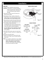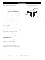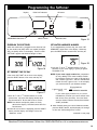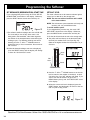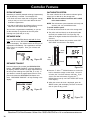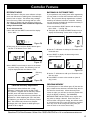
1
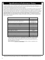
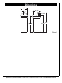
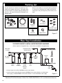
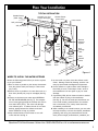
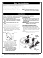
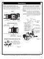
Use & Care Guide
Manual de Uso y Cuidado
System tested and certified by NSF
International against NSF/ANSI Standard 44
for hardness reduction and efficiency,
and certified to NSF/ANSI Standard 372.
®
English / Español
Este sistema ha sido probado y certificado
por NSF International
según la norma NSF/ANSI 44
para la reducción de la dureza y eficiencia,
y certificado según la norma NSF/ANSI 372.
Kenmore
Water Softener
Model / Modelo No. 625.383000
®
with High Flow Valve
Ablandador de Agua
con válvula de alto flujo
Sears Brands Management Corporation
3333 Beverly Road
Hoffman Estates, IL 60179 U.S.A.
www.kenmorewater.com
www.kenmore.com
www.sears.com
P/N 7332856 (Rev. D 10/8/12)
Warranty
WARRANTY ON KENMORE WATER SOFTENER
ONE YEAR LIMITED WARRANTY ON WATER SOFTENER
When installed, operated and maintained according to all instructions supplied with the product, if this
Kenmore appliance fails due to a defect in material and workmanship within one year from the date of purchase, call 1-800-4-MY-HOME® to arrange for free repair.
TEN YEAR LIMITED WARRANTY AGAINST LEAKS
When installed, operated and maintained according to all instructions supplied with the product, if the water
softener tank or salt storage drum develops a leak within ten years from the date of purchase,
call 1-800-4-MY-HOME® to arrange for free tank or drum replacement. After the first year you must pay an
initial trip charge.
All warranty coverage does not include water softener resin, which is an expendable item.
If this appliance is used for other than private family purposes, this warranty applies for only 90 days from
the date of purchase.
This warranty covers only defects in material and workmanship. Sears will NOT pay for:
1. A service technician to instruct the user in correct product installation, operation or maintenance.
2. A service technician to clean or maintain this product.
3. Damage to or failure of this product if it is not installed, operated or maintained according to the all
instructions supplied with the product.
4. Damage to or failure of this product resulting from accident, abuse, misuse or use for other than its intended purpose.
5. Damage to or failure of this product caused by the use of detergents, cleaners, chemicals or utensils other
than those recommended in all instructions supplied with the product.
6. Damage to or failure of parts or systems resulting from unauthorized modifications made to this product.
Disclaimer of implied warranties; limitation of remedies
Customer’s sole and exclusive remedy under this limited warranty shall be product repair as provided herein.
Implied warranties, including warranties of merchantability or fitness for a particular purpose, are limited to
one year or the shortest period allowed by law. Sears shall not be liable for incidental or consequential damages. Some states and provinces do not allow the exclusion or limitation of incidental or consequential damages, or limitation on the duration of implied warranties of merchantability or fitness, so these exclusions or
limitations may not apply to you.
This warranty applies only while this appliance is used in the United States or Canada.
This warranty gives you specific legal rights, and you may also have other rights which vary from state to
state.
Sears Brands Management Corporation, Hoffman Estates, IL 60179 U.S.A.
2
Questions? Call the Kenmore Water Line 1-800-426-9345 or visit www.kenmorewater.com
Table of Contents
Warranty . . . . . . . . . . . . . . . . . . . . . . . . . . . . . . . . . . . . . . . . . . . . . . . . . . . . . . . . . . . . . . . . . . . . . . . . . . . . . . . . . . . . . 2
Safety Guides . . . . . . . . . . . . . . . . . . . . . . . . . . . . . . . . . . . . . . . . . . . . . . . . . . . . . . . . . . . . . . . . . . . . . . . . . . . . . . . . . . 3
Specifications & Performance Claims . . . . . . . . . . . . . . . . . . . . . . . . . . . . . . . . . . . . . . . . . . . . . . . . . . . . . . . . . . . . . . . 4
Dimensions . . . . . . . . . . . . . . . . . . . . . . . . . . . . . . . . . . . . . . . . . . . . . . . . . . . . . . . . . . . . . . . . . . . . . . . . . . . . . . . . . . . . 5
Packing List . . . . . . . . . . . . . . . . . . . . . . . . . . . . . . . . . . . . . . . . . . . . . . . . . . . . . . . . . . . . . . . . . . . . . . . . . . . . . . . . . . . 6
Plan Your Installation . . . . . . . . . . . . . . . . . . . . . . . . . . . . . . . . . . . . . . . . . . . . . . . . . . . . . . . . . . . . . . . . . . . . . . . . . . 6-8
Installation . . . . . . . . . . . . . . . . . . . . . . . . . . . . . . . . . . . . . . . . . . . . . . . . . . . . . . . . . . . . . . . . . . . . . . . . . . . . . . . . . . 8-12
Programming the Softener . . . . . . . . . . . . . . . . . . . . . . . . . . . . . . . . . . . . . . . . . . . . . . . . . . . . . . . . . . . . . . . . . . . . . 13-14
Sanitizing the Water Softener . . . . . . . . . . . . . . . . . . . . . . . . . . . . . . . . . . . . . . . . . . . . . . . . . . . . . . . . . . . . . . . . . . . . 15
Adding Salt to the Storage Tank . . . . . . . . . . . . . . . . . . . . . . . . . . . . . . . . . . . . . . . . . . . . . . . . . . . . . . . . . . . . . . . . . . 15
Controller Features . . . . . . . . . . . . . . . . . . . . . . . . . . . . . . . . . . . . . . . . . . . . . . . . . . . . . . . . . . . . . . . . . . . . . . . . . . . 16-17
Care of Your Water Softener . . . . . . . . . . . . . . . . . . . . . . . . . . . . . . . . . . . . . . . . . . . . . . . . . . . . . . . . . . . . . . . . . . . . . 18
Service Information . . . . . . . . . . . . . . . . . . . . . . . . . . . . . . . . . . . . . . . . . . . . . . . . . . . . . . . . . . . . . . . . . . . . . . . . . . 18-21
Exploded View & Parts List . . . . . . . . . . . . . . . . . . . . . . . . . . . . . . . . . . . . . . . . . . . . . . . . . . . . . . . . . . . . . . . . . . . . 22-25
Safety Guides
p Read all steps and guides carefully before installing
p
p
p
p
and using your new water softener. Follow all steps
exactly to correctly install. Failure to follow them
could cause personal injury or property damage.
Reading this manual will also help you to get all the
benefits from your water softener.
Your Kenmore water softener will remove hardness
minerals from water. This is measured in grains per
gallon (gpg). It will also remove some clear water
iron*. This is measured in parts per million (ppm).
See the specifications page for the maximum limits
of hardness and iron removal.
A water softener will not improve other water problems such as acidity, tastes and odors, or iron other
than clear water iron.
Do not attempt to use this product to make safe
drinking water from non-potable water sources. Do
not use the system on microbiologically unsafe water,
or water of unknown quality without adequate disinfection before or after the system.
Check with your local public works department for
plumbing and sanitation codes. You must follow
their guides as you install the system. Follow your
local codes if they differ with guides in this manual.
In Massachusetts, plumbing code 248-CMR 3.00 and
10.00 shall be adhered to. Consult with a licensed
plumber.
* The capacity to reduce clear water iron is substantiated
by Water Quality Association test data.
p Use only lead-free solder and flux for all sweat-solder
p
p
p
p
p
p
p
connections, as required by federal codes, when
installing soldered copper plumbing.
Use care when handling the water softener. Do not
turn upside down or drop.
Avoid installing in direct sunlight. Excessive heat may
cause distortion or other damage to non-metallic parts.
This water softener works on water pressures of 20 psi
(minimum) to 125 psi (maximum). If your house water
pressure is over the maximum, install a pressure reducing valve in the water supply pipe to the softener.
Temperature of the water supply to the softener must be
between 40°F and 120°F. Do not install on hot water.
If installing the water softener outdoors, do not locate
where it will be exposed to wet weather, direct sunlight
or extreme hot or cold temperatures.
This softener works on 24 volt, 60 Hz electrical power
only, supplied by a direct plug-in transformer (included). Be sure to use the included transformer and plug
it into a nominal 120V, 60 cycle household outlet that
is properly protected by an overcurrent device such as
a circuit breaker or fuse. If transformer is replaced,
use only the authorized service, Class II, 24V 10VA
transformer.
This water softener has a non-metallic valve system.
Installing it on metal plumbing will break electrical
continuity, which may interrupt grounding for the
home. You must restore electrical continuity in your
metal plumbing system (See Page 12).
European Directive 2002/96/EC requires all electrical and electronic
equipment to be disposed of according to Waste Electrical and Electronic
Equipment (WEEE) requirements. This directive or similar laws are in
place nationally and can vary from region to region. Please refer to your
state and local laws for proper disposal of this equipment.
Questions? Call the Kenmore Water Line 1-800-426-9345 or visit www.kenmorewater.com
3
Specifications & Performance Claims
This model is efficiency rated. The efficiency rating is valid only at the minimum salt dose. The softener has a
demand initiated regeneration (D.I.R) feature that complies with specific performance specifications intended to minimize the amount of regenerant brine and water used in its operation.
This softener has a rated softener efficiency of not less than 3,350 grains of total hardness exchange per pound of salt
(based on sodium chloride) and shall not deliver more salt than its listed rating or be operated at a sustained maximum service flow rate greater than its listed rating. This softener has been proven to deliver soft water for at least ten
continuous minutes at the rated service flow rate. The rated salt efficiency is measured by laboratory tests described
in NSF/ANSI Standard 44. These tests represent the maximum possible efficiency that the system can achieve.
Operational efficiency is the actual efficiency after the system has been installed. It is typically less than the rated
efficiency, due to individual application factors including water hardness, water usage, and other contaminants that
reduce a softener's capacity.
Model Code
Rated Softening Capacity (Grains @ Salt Dose)
Rated Efficiency (Grains/Pound of Salt @ Minimum Salt Dose)
Water Used During Regeneration @ Minimum Salt Dose
Total Water Used Per Regeneration @ Maximum Salt Dose
Rated Service Flow Rate
Amount of High Capacity Ion Exchange Resin
Pressure Drop at Rated Service Flow
Water Supply Max. Hardness
Water Supply Max. Clear Water Iron
Water Pressure Limits (minimum / maximum)
Water Temperature Limits (minimum / maximum)
Minimum Water Supply Flow Rate
Maximum Drain Flow Rate
Model No. 625.383000
300
8,300 @ 1.7 lbs.
20,400 @ 6.5 lbs.
24,400 @ 11.0 lbs.
4,880 @ 1.7 lbs.
2.3 gallons / 1,000 grains
26.6 gallons
7.3 gpm
0.68 cu. ft.
15 psig
70 gpg
3 ppm*
20 - 125 psi
40 - 120 °F
3 gpm
0.9 gpm
* Capacity to reduce clear water iron is substantiated by WQA test data. State of Wisconsin
requires additional treatment if water supply contains clear water iron exceeding 5 ppm.
This system conforms to NSF/ANSI Standard 44 for the specific performance claims as verified and substantiated by test data.
Variable Salt Dose: The salt dose is selected by the electronic controls at regeneration time
based on the amount needed.
4
Questions? Call the Kenmore Water Line 1-800-426-9345 or visit www.kenmorewater.com
Dimensions
16-1/2”
16-1/2"
3-3/8”
3-3/8"
OUT
OUT
19-3/4”
19-3/4"
IN
IN
IN
OUT
IN --OUT
41-1/2”
41-1/2"
40-1/4”
40-1/4"
FRONT VIEW
FRONT
VIEW
SIDE VIEW
VIEW
SIDE
46"
46”
Figure 1
Questions? Call the Kenmore Water Line 1-800-426-9345 or visit www.kenmorewater.com
5
Packing List
The parts required to assemble and install the water
softener are included with the unit. Thoroughly check
the water softener for possible shipping damage and
parts loss. Also inspect and note any damage to the
shipping carton.
Remove and discard (or recycle) all packing materials.
To avoid loss of small parts, we suggest you keep the
small parts in the parts bag until you are ready to use
them.
Small Parts
Bypass Valve
Drain Hose
Installation
Adaptors
Grommet
Hose Clamps
Clips
(including 1 spare)
Figure 2
Adaptor Elbow
Plan Your Installation
THE PROPER ORDER TO INSTALL WATER TREATMENT EQUIPMENT
(Shows sequence of equipment only - not all items are needed in all applications)
Untreated Water to
Outside Faucets
Cold Water
to House
City Water Supply
Sediment
Cartridge
Filter
Hot Water
to House
Water
Heater
Water
Softener
Central
Water
Filtration
System
Iron
Filter
Pressure
Tank
OR
Well Water Supply
Always locate an Iron Filter UPSTREAM of the water softener.
= Locate a Central Water Filtration System UPSTREAM of the water softener on a chlorinated
water supply, or DOWNSTREAM of the water softener on a non-chlorinated water supply.
Well
Pump
=
6
Figure 3
Questions? Call the Kenmore Water Line 1-800-426-9345 or visit www.kenmorewater.com
Plan Your Installation
TYPICAL INSTALLATION
Grounding wire must
connect metal pipes
Hard W
Soft, hot water
Soft W
a
ater Lin
e
ter Line
Soft Water
to R.O.
System
Shutoff
Valve
120V,
60 Hz
Hard
Water
to
House
Water
Heater
to R.O. Faucet
Reverse
Osmosis
System
R.O.
Storage
Tank
ain
Soft, cold water)
Outside Faucet
(hard water)
R.O. Dr
Outside Faucet
(hard water)
Water
Meter
Water
Softener
1-1/2”
Floor Air Gap
Drain
Main
Shutoff
Valve
Figure 4
WHERE TO INSTALL THE WATER SOFTENER
Review the following points before you choose a place
to put your softener:
1. Place as close as possible to, but always downstream
from, the pressure tank (well water) or water meter
(city water).
2. Place as close as possible to a water drain such as a
floor drain, laundry tub, sump or standpipe (See Fig.
4).
3. Connect to the house main water pipe UPSTREAM
OF THE WATER HEATER (See Fig. 3). The temperature of water going through the softener must not be
more than 120°F (49°C). Hot water will damage
inner softener parts. To reduce the risk of hot water
backup, piping between the softener and water
heater should be as long as possible.
4. Keep outside faucets on hard water to save soft
water and salt. See Fig. 4.
5. Do not install in a place where the softener could
freeze. Damage caused by freezing voids the warranty by Sears Brands Management Corporation.
6. Put the softener in a place where water damage is
least likely to occur if it develops a leak. Sears or
the manufacturer will not repair or pay for water
damage.
7. A grounded, 120V, 60 Hz. electrical outlet is needed
near the softener to plug in the transformer
(See Fig. 4). Be sure the outlet and transformer are
in an inside location, protected from wet weather.
Use a continuously “live” outlet, which cannot be
accidentally switched off.
8. When installing in an outside location, you must take
the steps necessary to assure the softener, installation
plumbing, and wiring, are protected from the elements, direct sunlight, contamination, vandalism, etc.
Questions? Call the Kenmore Water Line 1-800-426-9345 or visit www.kenmorewater.com
7
Plan Your Installation
CHECK YOUR WATER PRESSURE BEFORE INSTALLING
For your water softener to work properly, incoming
water pressure in your house pipes must be no lower
than 20 pounds per square inch (psi). The highest
allowable pressure is 125 psi. If pressure is above 125
psi, buy and install a pressure reducing valve in the
pipe supplying water to the softener’s inlet.
NOTE: If water pressure during the day is 100 psi or
more, pressure during the night may go above
125 psi.
Installation
INSTALL SINGLE BYPASS VALVE AND/OR THREADED INSTALLATION ADAPTORS
Complete the following steps to assemble the adaptors
and/or the included single bypass valve.
1. Close the shutoff valve on the house main water pipe,
near the water meter or pressure tank, to turn off the
water.
2. Shut off the gas or electric supply to the water
heater.
3. Open the highest and lowest water faucets in your
house. This will let water drain from the pipes.
Close faucets after water has drained.
4. Remove the top cover. Remove the salt lid first and
then pull outward on the two tabs to release top
cover (see Fig. 5). Set both covers aside so they will
not get scratched or broken.
Salt Lid
Top Cover
SINGLE BYPASS VALVE:
6. Push the bypass valve into the softener valve’s inlet
and outlet ports as far as it will go. Snap the two
large holding clips into place, from the top down as
shown (see Fig. 8).
CAUTION: Be sure the clips snap firmly into place so
the bypass valve will not pull out.
INLET AND OUTLET THREADED ADAPTORS:
7. Push the adaptors into the valve inlet and outlet
ports, or bypass valve ports, as far as they will go.
Both adaptors are the same and fit either port. Snap
the two large holding clips into place, as shown (see
Fig. 8).
CAUTION: Be sure the clips snap firmly into place so
the adaptors will not pull out.
Clips
Valve
Outlet
Threaded
Installation
Adaptors
Figure 5
5. Visually check and remove any foreign
materials from the valve inlet and outlet
ports (see Fig. 6). Carefully remove the
two large plastic clips (you will use them).
Check to be sure the turbine and support
are firmly in place (see Fig. 7).
NOTE: If you will not install the included
bypass valve because you will have
a 3-valve bypass in your plumbing,
skip step 6, but perform step 7.
8
Clip
Valve Inlet
Clip
Single
Bypass Valve
Figure 6
Questions? Call the Kenmore Water Line 1-800-426-9345 or visit www.kenmorewater.com
Installation
INSTALL SINGLE BYPASS VALVE (cont.)
ASSEMBLE INLET AND OUTLET PLUMBING
Before installing the bypass valve and/or installation
adaptors, make sure that the turbine and support are
firmly in place inside the softener valve’s outlet port.
Measure, cut (thread if needed) and put together all
pipe and fittings up to the main water pipe. Make sure
that the incoming water supply pipe goes to the valve
inlet side.
CAUTION: Never solder fittings while connected to
nonmetallic parts. Wait until soldered pipe
has cooled before connection. See Fig. 10.
CAUTION: Be careful when putting pipe fittings together. Do not cross thread, and do not overtighten.
Turbine
Support
Valve Outlet
Turbine
Figure 7
Plastic Clip
Valve Inlet or Outlet
O-Ring
Plastic clip snaps
into groove in
Figure
bypass or adaptor
Wate
r Pipe
4. Solder.
NOTE: To be certain
that heat will not
travel down the pipe
and into the bypass
valve or installation
adaptors, wrap the
bottom of the pipe
and the bypass valve
with a wet rag.
INSTALL HOLDING CLIPS
Bypass Valve or
Installation Adaptor
Main
Incoming
Hard
Water
1. Cut pipe to
correct length
2. Solder. When
cool, do step 3.
IN
3. Put threaded
adaptor into
bypass valve
port.
8
ALTERNATE BYPASS VALVE INSTALLATION
Figure 10
If connecting to floor
level plumbing, install
the bypass valve turned
downward, as shown.
IN
OUT
Figure 9
Questions? Call the Kenmore Water Line 1-800-426-9345 or visit www.kenmorewater.com
9
Installation
CONNECT THE VALVE DRAIN HOSE
Take a length of 3/8” inside diameter drain tubing
(supplied) and attach one end to the drain fitting (see
Fig. 11). Use a tube clamp from the parts bag to hold it
in place. Put the other end of the tubing over a floor
drain, into a laundry tub, standpipe, or other suitable
drain. Check your local codes.
Leave an air gap of about 1-1/ 2'' between the end of
the hose and the drain. This gap is needed so you
don’t get a backflow of sewer water into the softener.
Do not put the end of the hose into the drain or connect without the air gap.
Locate and support the hose so it does not kink or have
sharp bends. Secure the hose end so water pressure
does not cause the hose to “whip”. Tie or wire it in
place. Do not pinch the hose shut. The softener will
not work if this drain hose is pinched, plugged, closed
or restricted in any way. Direct drain flow down into
drain from drain line as flow could possibly overshoot
the drain cover.
Keep the hose lower than the drain fitting. In some
homes, to get to a drain you must raise the hose and
run it overhead. Do not raise the hose more than 8 feet
above the floor.
COPPER DRAIN TUBE: Local plumbing codes may
require the use a copper valve drain tube. A copper
tube is also best to use if running a drain line overhead.
To adapt a copper drain tube to the softener, purchase
a compression fitting (1/4'' female pipe threads x 1/2''
O.D. tube) and tubing from your local hardware store.
CONNECT SALT TANK OVERFLOW HOSE
1. Locate the rubber grommet, adaptor elbow and tube
clamp (see Fig. 11) that are in the parts bag.
2. Push the grommet into the hole in the salt tank wall
so that half is inside and half is outside.
3. Push the larger end of the adaptor into the grommet.
4. Push one end of a length of 3/8'' I.D. tubing (supplied) onto the tube adaptor, using a tube clamp
from the parts bag to hold it in place.
5. Put the other end of the tubing over the floor drain.
IMPORTANT: Overflow water must run down by gravity
through the tubing. Do not raise the tubing higher than the adaptor (see Fig. 11).
IMPORTANT: Do not connect this hose to the valve
drain hose you just installed (see above).
Both drains must have a separate hose.
1/4 NPT
Threads
Drain
Fitting
Grommet
Tube
Clamp
10
1/2” Outside
Diameter Copper
Tube (not supplied)
Cut barbs from
drain fitting (pull
clip and remove
fitting from valve) Compression Fitting,
1/4 NPT x 1/2” O.D.
Tube (not supplied)
Valve
Drain Hose
Salt Tank
Overflow Hose
Barbs
Clip
Tube
Adaptor
Tube
Clamp
NOTE: Drain Hose
(20 ft.) is included.
See also parts list.
SUBSTITUTING RIGID DRAIN LINE
Tie or wire
tubing in
place
1-1/2”
Air Gap
FLOOR DRAIN
To drain
point other
than floor
drain.
Support tubing in place
as needed.
STANDPIPE
1-1/2”
Air Gap
1-1/2”
Air Gap
LAUNDRY TUB
Figure 11
Questions? Call the Kenmore Water Line 1-800-426-9345 or visit www.kenmorewater.com
Installation
LEAK TEST
To check for leaks, complete the following steps:
CAUTION: To avoid water or air pressure damage to
softener inner parts, and to flush pipe chips
or other residue from the water pipes, be
sure to do the following steps exactly as
instructed.
1. Fully open two nearby cold water faucets downstream from the softener.
2. Place bypass valve(s) in “bypass” position (see
Figures 12 & 13). On a single valve, slide the stem
inward to bypass. On a 3-valve bypass, close the
inlet and outlet valves and open the bypass valve.
3. Fully open the house main water pipe shutoff valve.
Observe steady water flow from both open faucets.
4. Place bypass valve(s) in SERVICE, EXACTLY as follows: Keep soft water faucets open.
a. Single Bypass Valve: Slowly, slide pull the valve
stem outward toward service, pausing several times
to allow the softener to pressurize gradually.
b. 3-Valve Bypass: Fully close the bypass valve and
open the outlet valve. Slowly open the inlet valve,
pausing several times to allow the softener to pressurize gradually.
5. After about three minutes, open a hot water faucet
for about one minute, or until all air is expelled, then
close.
6. Close both cold water faucets.
7. Check your plumbing work for leaks, and fix right
away if any are found. Be sure to observe previous
caution notes.
NOTE: If this procedure is performed on a new softener,
water coming from the taps may initially be discolored. This normally occurs the first time
water runs through the resin bed. The discolored water is not harmful, and the discoloration
will not last more than a few minutes.
SINGLE BYPASS VALVE
Pull stem outward
for Service
Push inward
for Bypass
Figure 12
3-VALVE BYPASS
FOR SERVICE
Close bypass valve.
Open inlet & outlet
valves.
FOR BYPASS
Open bypass valve.
Close inlet & outlet
valves.
Outlet
Valve
Bypass
Valve
Inlet
Valve
Figure 13
Questions? Call the Kenmore Water Line 1-800-426-9345 or visit www.kenmorewater.com
11
Installation
METAL WATER PIPE GROUNDING
IMPORTANT: This water softener has a non-metallic
valve system. Installing it on metal
plumbing will break electrical continuity,
which may interrupt grounding for the
home. You must restore electrical continuity in your metal plumbing system.
If you installed a 3-valve bypass system (Fig. 13), electrical continuity will be maintained. If you installed the
non-metallic bypass valve (Fig. 12), restore the ground
as follows:
Install a #4 copper wire (parts not included) across the
removed section of metal water pipe, securely clamping
it at both ends (See Fig. 14). Be sure the pipes are
clean under the clamps, to assure good contact.
NOTE: If you are installing a sediment filter or other
item(s) into the plumbing system, along with the
water softener, be sure to restore electrical continuity across all removed metal pipe sections.
METAL PIPE GROUNDING
(parts not included)
Ground Wire
Clamp (2)
Figure 14
INSTALL COVERS
After installing your water softener, put the covers on.
Angle the covers so the top cover clips onto the back
first, then bring down in front and clip on the tabs
inside the rim and lower the salt lid closed (See Fig. 5).
CONNECT TO ELECTRICAL POWER
The softener works on 24 volt, 60 Hz electrical power.
The included transformer changes standard 120 volt AC
house power to 24 volts. You must plug the water softener’s transformer into a grounded, 120 volt outlet only.
Be sure the outlet is always “live” so it cannot be
switched off by mistake.
NOTE: The electrical outlet you plug the transformer
into must be indoors, protected from weather.
RESTART THE WATER HEATER
Turn on the gas (or electric) supply to the water heater
and light the pilot.
YOUR PLUMBING INSTALLATION AND
ELECTRICAL WORK ARE NOW COMPLETE.
12
Questions? Call the Kenmore Water Line 1-800-426-9345 or visit www.kenmorewater.com
Programming the Softener
Display
LOW SALT indicator
UP button
Low Salt
press for tonight
Select
hold for immediate
REGENERATION button
SELECT button
PROGRAM THE SOFTENER
When the transformer is plugged into the electrical outlet, the model code (300) and a test number (example:
J3.0), are briefly shown in the display. Then the words
“SET TIME” appear and 12:00 PM begins to flash.
DOWN button
Figure 15
SET WATER HARDNESS NUMBER
If you completed the previous step, the words “SET
HARDNESS" should show in the display. Otherwise,
press the SELECT button several times until they do.
Figure 18
SET PRESENT TIME OF DAY
Figure 16
If the words “SET TIME" do not show in the display,
press the SELECT button a few times until they do.
Figure 17
1. Press the r UP or s DOWN buttons to set the
present time. Up moves the display ahead; down
sets the time back. Be sure AM or PM is correct.
NOTE: Press buttons and quickly release to slowly
advance the display. Hold the buttons down for
fast advance.
2. When the correct time is displayed, press the SELECT
button, and the display will change to show the
“Hardness” screen.
1. Press the r UP or s DOWN buttons to set the
hardness of your water supply, in grains per gallon.
The default is 25.
NOTE: If your water supply contains iron, compensate
for it by adding to the water hardness number.
For example, assume your water is 20 gpg hard
and contains 2 ppm iron. Add 5 to the hardness
number for each 1 ppm of iron. In this example,
you would use 30 for your hardness number.
20 gpg hardness
2 ppm iron x 5 = 10 +10
(times)
30 HARDNESS NUMBER
If your water supply contains iron, it is recommended that you clean your water softener resin
bed at least every 6 months. Your local Sears
store has Water Softener Cleaner (Part Number
34427) available.
2. When finished setting your water’s hardness number,
press the SELECT button, and the display will change
to show the “Set Recharge Time” screen.
continued on next page
Questions? Call the Kenmore Water Line 1-800-426-9345 or visit www.kenmorewater.com
13
Programming the Softener
SET RECHARGE (REGENERATION) START TIME
If you completed the previous step, the words “SET RECHARGE TIME" should show in the display. Otherwise,
press the SELECT button several times until they do.
Figure 19
1. The softener’s default recharge start time is 2:00 AM.
This is normally a time of day when water is not
being used in the household. Hard water bypasses
the softener if the household draws water during the
recharge cycle. If a different recharge start time is
desired, press the r UP or s DOWN buttons to
change the time, in 1-hour increments. Be sure AM or
PM is correct.
2. When the desired recharge start time is displayed,
press the SELECT button, and the display will change
to show the “Set Salt Level” screen.
SET SALT LEVEL
The water softener has a salt monitor indicator light to
remind you to add salt to the storage tank.
NOTE: You must set salt level each time salt is added
to the water softener.
NOTE: The salt monitor system estimates salt levels, and
accuracy will vary with different salts.
To set this monitor system:
If you completed the previous step, the words “SET
SALT LEVEL" should show in the display. Otherwise,
press the SELECT button several times until they do.
1. Lift the salt lid and level the salt in the storage tank.
2. The yellow salt level decal, on the brinewell inside
the tank, has numbers from 0 to 8 (see Fig. 20).
Observe the highest number the leveled salt is at, or
closest to.
SALT
LEVEL
Brinewell
Salt
Level
Decal
Figure 20
3. Press the r UP or s DOWN buttons to set the salt
level to match to the number on the decal. At level
2 or below, the “Low Salt" indicator will flash. If you
want to turn the salt monitor off, press the s
DOWN button past 0, until “SALT LEVEL OFF” shows
in the display.
4. When the correct salt level is displayed, press the
SELECT button, and the display will return to the normal run (time of day) screen.
Figure 21
14
Questions? Call the Kenmore Water Line 1-800-426-9345 or visit www.kenmorewater.com
Sanitizing the Softener
SANITIZE THE WATER SOFTENER
1. Open salt lid, remove the brinewell cover and pour
about 3 oz. (6 tablespoons) of household bleach into
the softener brinewell. Replace the brinewell cover.
2. Make sure the bypass valve(s) is in the “service”
(open) position.
3. Start a recharge: Press the REGENERATION button
and hold for 3 seconds, until “RECHARGE NOW”
begins to flash in the display. This recharge draws
the sanitizing bleach into and through the water softener. Any air remaining in the unit is purged to the
drain.
4. After the recharge has completed, fully open a cold
water faucet, downstream from the softener, and
allow 50 gallons of water to pass through the system. This should take at least 20 minutes. Close the
faucet.
Your new Sears softener is now softening the water for
your household needs. However, your WATER HEATER
is filled with hard water. To have fully soft water right
away, you can drain the water heater so it refills with
soft water. If you don’t drain the water heater, it will
take a few days before you have fully soft water.
NOTE: If this procedure is performed on a new softener,
water coming from the taps may initially be discolored. This normally occurs the first time
water runs through the resin bed. The discolored water is not harmful, and the discoloration
will not last more than a few minutes.
Adding Salt to the Storage Tank
ADDING SALT TO THE STORAGE TANK
You must keep salt in the tank, but it is not necessary to
fill it full. Especially in humid areas, it is best to fill the
storage tank no more than half full, and to add salt
more often. Salt “bridging” occurs more often when
conditions are humid.
Use NUGGET or PELLET water softener salt. DO NOT
use rock salts, as they have dirt and sediments that will
stop the softener from working. To maintain optimum
performance of your water softener, the salt tank
should be cleaned out every 2 to 3 years.
POTASSIUM CHLORIDE (KCl) SALT
If you choose Potassium Chloride (KCl) as a regenerant,
following these suggestions will help give you years of
maintenance free service.
1. Place only one bag of KCl in your softener at a time
(the salt storage tank should contain no more than
60 pounds of KCl at any one time).
2. A softener using KCl should not be placed in areas
with temperature fluctuations and high humidity (KCl
will harden in these environments and may make the
softener inoperable).
3. Check the brine tank and brinewell (black tube in
salt storage tank) monthly. If hardening is present,
pour small amounts of warm water onto hardened
areas until they loosen.
4. If your softener does not have a KCl salt setting, you
must increase your hardness setting by 25% to
ensure continuous soft water. See table at right.
Untreated Water Hardness
(grains per gallon)
5 gpg
10 gpg
15 gpg
Softener Setting when
using KCl salt (add 25%)
7 gpg
13 gpg
19 gpg
20 gpg
25 gpg
30 gpg
40 gpg
40 gpg
50 gpg
25 gpg
35 gpg
35 gpg
45 gpg
Persons who are on sodium restricted diets should consider the added sodium as part of their overall sodium
intake. For example, if your water supply is 15 grains
hard, and you drank 3 quarts of softened water you
would consume 335 milligrams of sodium. That is
equivalent to eating 2-1/2 slices of white bread.
WATER SOFTENING SALT WITH IRON
REMOVING ADDITIVES
Some salts have an additive to help the softener handle
iron in the water supply. These salts may be used if
your water supply has a high iron content. It is recommended to use Sears Water Softener Cleaner (refer to
the parts list in back of manual for part number) for
periodic treatments to keep your resin bed clean. This
is available at your local Sears store.
Persons who are concerned about their drinking water
should consider a Kenmore reverse osmosis drinking
water system that will remove in excess of 90% of the
sodium and other drinking water contaminants.
Questions? Call the Kenmore Water Line 1-800-426-9345 or visit www.kenmorewater.com
15
Controller Features
EXTRA RECHARGE
Sometimes, a manually initiated recharge (regeneration)
may be desired, or needed. Two examples are:
= You have used more water than usual (guests visiting)
and you may run out of soft water before the next
automatic regeneration.
= You did not add salt to the softener before it ran out.
Add salt to the softener before regenerating.
You can start a regeneration immediately, or you can
set the controller to regenerate at the next preset
recharge time (2:00 AM, or as set).
RECHARGE NOW
Press the REGENERATION button and hold for 3 seconds, until the words “RECHARGE NOW” begin to
flash in the display. The softener enters the fill cycle of
regeneration immediately. This regeneration will take
about 2 hours to complete. Then, you will have soft
water again.
Figure 22
RECHARGE TONIGHT
Press and release (do not hold) the REGENERATION
button. “RECHARGE TONIGHT” will begin flashing in
the display, and the softener will begin regeneration at
the next preset recharge time (2:00 AM, or as set). If
you decide to cancel the regeneration before it starts,
press and release the REGENERATION button once
more. “RECHARGE TONIGHT” will stop flashing in the
display.
Figure 23
SALT MONITOR SYSTEM
The water softener has a salt monitor indicator light to
remind you to add salt to the storage tank.
NOTE: You must set salt level each time salt is added
to the water softener.
NOTE: The salt monitor system estimates salt levels, and
accuracy will vary with different salts.
To set this monitor system:
1. Lift the salt lid and level the salt in the storage tank.
2. The yellow salt level decal, on the brinewell inside
the tank, has numbers from 0 to 8 (see Fig. 24).
Observe the highest number the leveled salt is at, or
closest to.
3. Press the SELECT button once, and the words “SET
SALT LEVEL” should show in the display.
SALT
LEVEL
Brinewell
Salt
Level
Decal
Figure 24
4. Press the r UP or s DOWN buttons to set the salt
level to match the number on the decal. At level 2
or below, the “Low Salt" indicator will flash. If you
want to turn the salt monitor off, press the s
DOWN button past 0, until “SALT LEVEL OFF” shows
in the display.
5. When the correct salt level is displayed, press the
SELECT button, and the display will return to the normal run (time of day) screen.
Figure 25
16
Questions? Call the Kenmore Water Line 1-800-426-9345 or visit www.kenmorewater.com
Controller Features
EFFICIENCY MODE
When this feature is ON, the water softener will operate at salt efficiencies of 4000 grains of hardness per
pound of salt or higher. The softener may recharge
more often using smaller salt dosage and less water.
This softener is shipped with the efficiency feature set
OFF. Installations in the state of California require this
setting to be turned ON.
To turn this feature ON:
1. Press and hold the SELECT button until the display
shows “000 - -”.
BACKWASH & FAST RINSE TIMES
If you experience salty tasting water after regeneration,
you may need to increase the backwash and fast rinse
times. The cycle times during regenerations are determined by the softener’s electronic controller. However,
you may increase the backwash and fast rinse times, in
1 minute increments, as follows:
1. Press and hold the SELECT button until the display
shows “000 - -” (see Fig. 26).
2. Then press (do not hold) the SELECT button twice to
display the alternating screens shown in Figure 29.
Figure 26
2. Then press (do not hold) the SELECT button again.
Use the r UP button to turn “ON”.
Figure 29
3. Use the r UP button to add up to 15 minutes to the
backwash time.
4. Press SELECT to display the alternating screens
shown in Figure 30.
Figure 27
3. Press SELECT several times to return to the normal
run (time of day) screen. The efficiency icon will
only be displayed when this feature is ON.
Efficiency
Icon
Figure 28
California Efficiency Requirement
Your Kenmore Water Softener has a “High
Efficiency” feature that can be set ON or OFF.
This softener is shipped with the efficiency feature
set OFF, which will utilize the maximum rated
capacity while most often achieving maximum salt
efficiencies. When installing this unit in the State
of California, you MUST turn the efficiency feature
ON. The softener may initiate more frequent
recharges, but it will operate at 4000 grains per
pound of salt or higher.
Figure 30
5. Use the r UP button to add up to 15 minutes to the
fast rinse time.
6. Press SELECT to return to the normal run (time of
day) screen.
PROGRAM MEMORY
If electrical power to the softener goes off, the time display is blank but the electronic controller keeps the correct time for several hours. When electrical power
comes on again, you will have to reset the present time
only if the display is flashing. The HARDNESS,
RECHARGE TIME and SALT LEVEL never require resetting unless a change is desired. Even if the clock is
incorrect after a long power outage, the softener works
as it should to keep your water soft, however, regenerations may occur at the wrong time of day until you
reset the clock to the correct time of day.
Questions? Call the Kenmore Water Line 1-800-426-9345 or visit www.kenmorewater.com
17
Care of Your Water Softener
SALT BRIDGE
Sometimes, a hard crust or salt “bridge” forms in the
brine tank. It is usually caused by high humidity or the
wrong kind of salt. When the salt “bridges,” an empty
space forms between the water and the salt. Then, salt
will not dissolve in the water to make brine. Without
brine, the resin bed is not recharged and hard water
will result.
If the storage tank is full of salt, it is difficult to tell if
you have a salt bridge. A bridge may be underneath
loose salt. Take a broom handle, or like tool, and hold
it next to the water softener. Measure the distance
from the floor to the rim of the water softener. Then,
gently push the broom handle straight down into the
salt. If a hard object is felt before the pencil mark is
even with the top, it is most likely a salt bridge. Gently
push into the bridge in several places to break it. Do
not use any sharp or pointed objects as you may puncture the brine tank. Do not try to break the salt bridge
by pounding on the outside of the salt tank. You may
damage the tank.
Push tool into
salt bridge
to break
1” - 2”
Pencil
Mark
Broom
Handle
Salt
Salt Bridge
Empty Space
Water Level
Figure 31
Service Information
ALWAYS MAKE THESE INITIAL CHECKS FIRST
1. Does the time display show the correct time of day?
= If display is blank, check power source to the softener.
= If time is flashing, power was off for a long period. The softener resumes normal operation but
regenerations occur at the wrong time.
= If an error code (example: “Err03”) shows in the
display, go to “Troubleshooting”.
2. Are bypass valve(s) fully in service position?
3. Are the inlet and outlet pipes connected to the softener inlet and outlet respectively?
4. Is the softener’s transformer plugged into a “live”,
grounded wall outlet, and the power cable fastened
securely to the controller?
18
5. Is the valve drain hose free of kinks and sharp bends,
and not elevated more than 8 ft. above the floor?
6. Is there salt in the storage tank?
7. Is the brine tubing connected? Brine tubing connects
to nozzle/venturi and brine valve assembly.
8. Press the SELECT button three times to display the
hardness setting. Make sure it is correct for the
household’s water supply. Perform a hardness test of
the untreated incoming water and compare with the
hardness setting. Also test a soft water sample to
verify if a problem exists. Press the SELECT button
twice more to return to present time display.
Questions? Call the Kenmore Water Line 1-800-426-9345 or visit www.kenmorewater.com
Service Information
TROUBLESHOOTING
If your water softener does not work properly, make the following easy checks. Often, you will find what is wrong
yourself and you won’t have to call and wait for service. If you do not find anything wrong while making the checks,
and your softener still does not work properly, call your Sears Service Department.
PROBLEM
CAUSE
CORRECTION
No soft water
No salt in the storage tank.
No soft water & display is blank
Transformer unplugged at wall outlet, or
power cable disconnected from back of
electronic board or transformer malfunction.
Add salt and then use RECHARGE NOW
feature.
Check for loss of power and correct.
Reprogram electronic control and then use
RECHARGE NOW feature.
Salt storage tank “bridged”.
Refer to “Breaking a Salt Bridge”.
No soft water & salt
level not dropping
No soft water & salt
storage tank full of
water
Intermittent hard
water
Fuse blown, circuit breaker tripped, or circuit switched off (see “Power Outage
Memory”).
Bypass valve(s) in “bypass” position.
Dirty, plugged or damaged nozzle & venturi assembly
Valve drain hose is plugged or restricted.
Incorrect time set.
Incorrect water hardness set.
Hot water being used when softener is
regenerating.
Possible increase in water hardness.
Brine tank flooded
Valve drain hose is plugged or restricted.
Salty tasting water
immediately after
regeneration
Dirty, plugged or damaged nozzle & venturi assembly.
Backwash and fast rinse cycle times are not
long enough.
Valve drain hose is plugged or restricted.
Error code appears
(example: “Err03”)
Fault in electronic controller or wiring harness connections to position switch, position
switch inoperable or motor inoperable.
Replace fuse, reset circuit breaker, or switch
circuit on, and then use RECHARGE NOW
feature.
Move bypass valve(s) to “service” position.
Take apart, clean and inspect nozzle & venturi (see instruction decal under salt lid).
Hose must not have any kinks, sharp bends or
any water flow blockage (See “Valve Drain
Requirements”).
Check and change time setting.
Refer to “Set Water Hardness Number” to
set correctly.
Avoid using hot water while the softener is
regenerating, as the water heater will fill with
hard water.
Test untreated water for hardness and iron.
Program the water softener accordingly (see
“Set Water Hardness Number”).
Hose must not have any kinks, sharp bends or
any water flow blockage (See “Valve Drain
Requirements”).
Take apart, clean and inspect nozzle & venturi (see “Cleaning the Nozzle & Venturi”).
Increase backwash & fast rinse times (see
“Back Wash & Fast Rinse Times”).
Hose must not have any kinks, sharp bends or
any water flow blockage (see “Valve Drain
Requirements”).
Unplug power cord. Check all wiring connections to be sure they are secure. Plug in
power cord and wait 8 minutes. If error
code returns, call Kenmore Water Line.
Questions? Call the Kenmore Water Line 1-800-426-9345 or visit www.kenmorewater.com
19
Service Information
MANUALLY INITIATED ELECTRONIC DIAGNOSTICS
1. To enter diagnostics, press and hold the SELECT button until “000 - -” shows in the display.
Figure 32
TURBINE OPERATION: If no water is flowing through
the softener, the turbine indicator displays three zeros.
When water is flowing, a 000 to 199 count repeats for
each gallon of water passing through the turbine. To
check for positive operation of the turbine if zeros are
shown, open a nearby soft water faucet and observe
the turbine count. If you don’t get a reading in the display with faucet open, pull the sensor housing from the
valve outlet port (see Fig. 34). Pass a small magnet
back and forth in front of the sensor. You should get a
reading in the display. If you get a reading, unhook the
inlet and outlet plumbing and check the turbine for
binding.
Figure 33
POSITION SWITCH STATUS: With the valve in service,
or any of the recharge cycle positions, the position
switch indicator will show two dashes (switch open).
While the valve is rotating from one position to another,
the position switch indicator will show the letter “P”
(switch closed). There is likely a problem if indications
vary from this pattern.
OTHER INFORMATION: While in the diagnostics
screen, the following information is available and may
be beneficial for various reasons. This information is
retained by the electronic controller from the first time
electrical power is applied to the unit.
= Press and hold the r UP button to display the number of days this controller has had electrical power
applied.
= Press and hold the s DOWN button to display the
number of regenerations initiated by this controller
since the model code number was entered.
20
Motor
Sensor
Housing
Position
Switch
Turbine
Turbine
Support
& Shaft
Valve Outlet
Figure 34
NOTE: If the electronic controller is left in the diagnostic display (or a flashing display when setting
times or hardness), the normal time of day display automatically returns if a button has not
been pressed for 4 minutes. To return to the
diagnostic display, repeat step 1, above.
RESETTING TO FACTORY DEFAULTS
To reset the electronic controller to its factory default
for all settings (time, hardness, etc.):
1. Press the SELECT button and hold it until the display
changes twice to show “SET CODE” and the flashing
model code.
2. Press the r UP button to display a flashing “SoS”.
Figure 35
3. Press the SELECT button, and the electronic controller
will restart.
4. Set the present time, hardness, etc., as described on
pages 13 & 14.
Questions? Call the Kenmore Water Line 1-800-426-9345 or visit www.kenmorewater.com
Service Information
MANUAL ADVANCE REGENERATION CHECK
This check verifies proper operation of the valve motor,
brine tank fill, brine draw, regeneration flow rates, and
other controller functions. Always make the initial
checks first, and perform the manually initiated electronic diagnostics.
NOTE: The display must show a steady time (not flashing). If an error code shows, first press the
SELECT button to enter the diagnostic display.
1. Press the REGENERATION button and hold in for 3
seconds. “RECHARGE NOW” begins to flash in the
display as the softener enters the fill cycle of regeneration.
2. When valve reaches “Fill” position, remove the
brinewell cover and, using a flashlight, observe fill
water entering the tank.
3. If water does not enter the tank, look for an
obstructed nozzle, venturi, fill flow plug, brine tubing,
or brine valve riser pipe.
4. After observing fill, press the REGENERATION button
to move the softener into brining. A slow flow of
water to the drain will begin. Verify brine draw
from the brine tank by shining a flashlight into the
brinewell and observing a noticeable drop in the liquid level.
5. If the softener does not draw brine:
= nozzle and/or venturi dirty
= nozzle and venturi not seated properly on gasket
= restricted drain (check drain fitting and hose)
= ineffective nozzle and venturi seal
= other inner valve problem (rotor seal, rotor & disc,
wave washer, etc.)
WIRING SCHEMATIC
Position Markers
(valve in service)
IN
OUT
Motor
Cam
Figure 36
NOTE: If water system pressure is low, an elevated
drain hose may cause back pressure, stopping
brine draw.
6. Again press REGENERATION to move the softener
into backwash. Look for a fast flow of water from
the drain hose.
7. An obstructed flow indicates a plugged top distributor, backwash flow plug or drain hose.
8. Press REGENERATION to move the softener into fast
rinse. Again look for a fast drain flow. Allow the
softener to rinse for a few minutes to flush out any
brine that may remain in the resin tank from the
brining cycle test.
9. To return the softener to service, press REGENERATION once more.
Back of Controller (PWA)
AC INPUT
POS. / TURBINE
MOTOR
Valve
Motor
24 VAC
Transformer
grn
Turbine
Sensor
OUT
GND
+5
brn
NO
NC
Position
Switch
Figure 37
Questions? Call the Kenmore Water Line 1-800-426-9345 or visit www.kenmorewater.com
21
Water Softener Exploded View
1
Kenmore
Model No.
625.383000
3
2
Valve Assembly
See Pages 24 & 25
for parts
4
5
25
24
6
Rating Decal
Location
26
22
21
23
20
19
7
27
18
8
9
11
17
13
15
14
12
28
29
16
10
22
Questions? Call the Kenmore Water Line 1-800-426-9345 or visit www.kenmorewater.com
Softener Parts List
Key
No.
1
2
3
Part No.
6
7
7275907
7324926
7324934
7325029
7327819
7324918
7324950
7324895
7219888
–
7327576
8
9
10
á
–
7214375
11
12
13
á
7324879
–
7331258
14
15
16
á
¢
4
5
¢
á
á
á
á
á
Description
Transformer, 24V, 10VA
Top Cover
Salt Lid (order decal below)
Instruction Decal
Repl. Electronic Controller (PWA)
Faceplate (order decal below)
Faceplate Decal
Rim
Brinewell Cover
Brinewell Mounting Hardware Kit
(includes Key Nos. 8-10)
Wing Nut, 1/4-20
O-Ring, 1/4” x 1/2”
Plastic, 1/4-20 x 5/8”
Brinewell Assembly
(includes Key Nos. 11 & 12)
Brinewell
Decal, Salt Level
Salt Storage Tank
Overflow Hose Adaptor Kit
(includes Key Nos. 14-16)
Adaptor Elbow
Grommet
Hose Clamp
Key
No.
17
18
19
Part No.
Description
7327584
0502272
7327607
–
7112963
20
21
22
23
24
á
7077870
7141001
–
7331177
25
26
27
28
29
á
Repl. Bottom Distributor
Resin
Repl. Resin Tank, 7” x 40”
Distributor O-Ring Kit
(includes Key Nos. 20-22)
O-Ring, 2-3/4” x 3”
O-Ring, 13/16” x 1-1/16”
O-Ring, 2-7/8” x 3-1/4”
Top Distributor
Vapor Barrier
Tank Neck Clamp Kit
(includes 2 ea. of Key Nos. 25 & 26)
Clamp Section (2 req.)
Retainer Clip (2 req.)
Cone Screen
Brine Valve Assembly
Float, Guide & Stem Assembly
Water Softener Cleaner Ù
Parts Bag (includes
5 ea. of Key No. 69,
2 ea. of Key Nos. 16 & 70,
1 ea. of Key Nos. 14, 15 & 97)
Owner’s Manual
á
á
á
¢
7171349
7310202
7327568
3442707
¢
7278573
¢
7332856
¢ Not illustrated.
Ù Not included with water softener.
Questions? Call the Kenmore Water Line 1-800-426-9345 or visit www.kenmorewater.com
23
Valve Assembly Exploded View
52
50
51
95
94
96
52
93
53
92
54
55
56
57
90
88
87
60
91
86
85
Wear Strip
Seal
62
Cross-Section
View
67
68
63
83
82
69
64
81
65
77
79
58
61
89
84
59
80
78
66
72
73
75
74
71
70
76
24
Questions? Call the Kenmore Water Line 1-800-426-9345 or visit www.kenmorewater.com
Valve Parts List
Key
No.
50
51
52
53
54
55
Part No.
Description
7224087
7286039
0900857
7231385
0503288
7284964
–
7331240
56
57
58
59
60
–
61
62
63
64
65
66
67
68
69
á
7082087
7199232
7116713
70
7278442
71
72
73
7170288
7092642
7129889
Screw, #8-32 x 1” (2 req.)
Motor (incl. 2 ea. of Key No. 50)
Screw, #6-20 x 3/8” (2 req.)
Motor Plate
Bearing
Cam & Gear
Drain Hose Adaptor Kit
(incl. Key Nos. 56-60)
Clip, Drain
Hose Clamp
Adaptor, Drain Hose
O-Ring, 5/8” x 13/16”
Flow Plug, 0.9 gpm
Seal Kit (includes Key Nos. 61-66)
O-Ring, 7/16” x 5/8”
O-Ring, 3/4” x 15/16”
O-Ring, 3-3/8” x 3-5/8”
Rotor Seal
O-Ring, 3/8” x 9/16”
Seal, Nozzle & Venturi
Bearing, Wave Washer
Rotor & Disc
Clip (4 req.)
Installation Adaptor, 1” NPT (2 req.,
includes 2 ea. of Key No. 71)
O-Ring 15/16” x 1-3/16” (2 req.)
Plug, Drain Seal
Spring
á
á
á
á
7129716
á
á
á
á
á
á
71
97
Key
No.
Part No.
–
7113040
74
75
76
77
78
79
á
7082053
7081201
7170319
1202600
–
7187065
80
81
82
84
85
86
87
88
89
90
7081104
7095030
1148800
7187772
7204362
0521829
7146043
7167659
7170262
7199729
7309803
7074123
–
7331266
91
92
93
94
95
á
7030713
7325702
7070412
96
7254260
97
7278434
¢
7139999
7123613
42-34405
42-34407
83
¢
¢
¢
á
á
Description
Turbine & Support Assembly
(includes 1 ea. of Key Nos. 74, 75
& 2 ea. of Key No. 71)
Turbine Support & Shaft
Turbine
Valve Body
Retainer, Nozzle & Venturi
O-Ring, 1/4” x 3/8” (2 req.)
Nut - Ferrule
Nozzle & Venturi Assembly
(includes Key Nos. 80-88)
Housing, Nozzle & Venturi
Cone Screen
Flow Plug, 0.3 gpm
Nozzle & Venturi Gasket Kit
Gasket (only)
Flow Plug, 0.1 gpm
Screen
Screen Support
O-Ring, 1-1/8” x 1-3/8”
Cap
Wire Harness (Sensor)
Screw, #10-14 x 2” (5 req.)
Valve Cover Assembly
(incl. Key Nos. 91 & 92)
Valve Cover
Expansion Pin
Switch
Spacer, Motor Mount
Screw, #4-24 x 1-1/8”, Flat Head
Installation Adaptor Kit,
(includes 2 ea. copper tubes, nuts,
clips & washers) Ù
Bypass Valve Assembly
(includes 2 ea. of Key No. 71)
Drain Tubing, 3/8” I.D. x 20 ft.
Silicone Grease (for O-Rings) Ù
Flexible Connectors, 3/4” Ù
Flexible Connectors, 1” Ù
¢ Not illustrated.
Ù Not included with water softener.
Questions? Call the Kenmore Water Line 1-800-426-9345 or visit www.kenmorewater.com
25
Get it fixed, at your home or ours!
Your Home
For expert troubleshooting and home solutions advice:
www.managemylife.com
For repair – in your home – of all major brand appliances,
lawn and garden equipment, or heating and cooling systems,
no matter who made it, no matter who sold it!
For the replacement parts, accessories and
owner’s manuals that you need to do-it-yourself.
For Sears professional installation of home appliances
and items like garage door openers and water heaters.
1-800-4-MY-HOME®
(1-800-469-4663)
Call anytime, day or night (U.S.A. and Canada)
www.sears.com
www.sears.ca
Our Home
For repair of carry-in items like vacuums, lawn equipment,
and electronics, call anytime for the location of your nearest
Sears Parts & Repair Service Center
1-800-488-1222 (U.S.A.)
www.sears.com
1-800-469-4663 (Canada)
www.sears.ca
To purchase a protection agreement on a product serviced by Sears:
1-800-827-6655 (U.S.A.)
1-800-361-6665 (Canada)
Para pedir servicio de reparación
a domicilio, y para ordenar piezas:
Au Canada pour service en français:
1-888-SU-HOGAR
(1-888-784-6427)
www.sears.com
®
1-800-LE-FOYERMC
(1-800-533-6937)
www.sears.ca
® Registered Trademark / TM Trademark of KCD IP, LLC in the United States, or Sears Brands, LLC in other countries
® Marca Registrada / TM Marca de Fábrica de KCD IP, LLC en Estados Unidos, o Sears Brands, LLC en otros países
MC
Marque de commerce / MD Marque déposée de Sears Brands, LLC