1
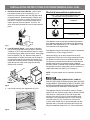
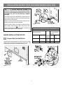
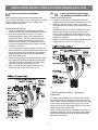
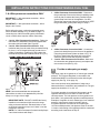
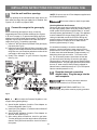
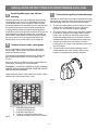
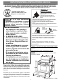
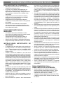
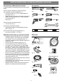
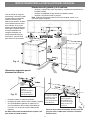
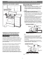
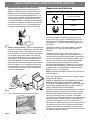
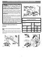
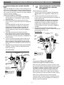
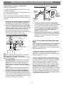
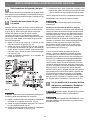
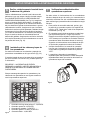
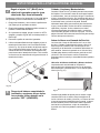
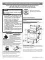
INSTALLATION INSTRUCTIONS FOR FREESTANDING DUAL FUEL
INSTALLATION AND SERVICE MUST BE PERFORMED BY A QUALIFIED INSTALLER.
IMPORTANT: SAVE FOR LOCAL ELECTRICAL INSPECTOR’S USE.
READ AND SAVE THESE INSTRUCTIONS FOR FUTURE REFERENCE.
If the information in this manual is
not followed exactly, a fire or explosion may
result causing property damage, personal
injury or death.
Refer to your serial plate for
applicable agency certifications
FOR YOUR SAFETY:
—
—
•
•
•
•
—
Do not store or use gasoline or other
flammable vapors and liquids in the
vicinity of this or any other appliance.
WHAT TO DO IF YOU SMELL GAS:
Do not try to light any appliance.
Do not touch any electrical switch; do not
use any phone in your building.
Immediately call your gas supplier from
a neighbor’s phone. Follow the gas
supplier’s instructions.
If you cannot reach your gas supplier, call
the fire department.
Installation and service must be performed
by a qualified installer, service agency or
the gas supplier.
Clearances and Dimensions
Location: Check location where the range will be installed.
Check for proper electrical and gas supply, and the stability
of the floor.
Dimensions that are shown must be used. Given
dimensions provide minimum clearance. Contact surface
must be solid and level.
Tip Over Hazard
• A child or adult can tip the
range and be killed.
• Verify the anti-tip device has
been installed to floor or wall.
• Ensure the anti-tip device is re-engaged to floor
or wall when the range is moved.
• Do not operate the range without the anti-tip
device in place and engaged.
• Failure to follow these instructions can result in
death or serious burns to children and adults.
Range
leveling leg
Provide Proper Fuel Type
Before proceeding: Your range is factory preset to operate on
natural gas. If L.P. conversion is needed, contact your local
L.P. Gas provider for assistance.
Anti-tip
bracket
The L.P. conversion kit may be located on the lower rear
back panel of the range. If no L.P. kit is provided, contact
your product dealer to obtain the correct L.P. conversion kit.
To check if the anti-tip bracket is installed properly, use
both arms to grasp the rear edge of the range back.
Carefully attempt to tilt range forward. When properly
installed, the range should not tilt forward.
Refer to the anti-tip bracket installation instructions
supplied with your range for proper installation.
1
PN 316454928 Rev A (1206)
INSTALLATION
INSTRUCTIONS FOR
DUAL FUEL
FUEL
INSTALLATION INSTRUCTIONS
FOR FREESTANDING
FREESTANDING DUAL
IMPORTANT NOTE TO THE CONSUMER
•
•
•
•
•
Keep these instructions with your Use & Care Guide
for future reference.
As when using any appliance generating heat, there
are certain safety precautions you should follow. These
are listed in the Use & Care Guide, read it carefully.
Be sure your range is installed and grounded properly
by a qualified installer or service technician.
Make sure the wall coverings around the range can
withstand the heat generated by the range.
To eliminate the need to reach over the surface
elements or burners, cabinet storage space directly
above the range should be avoided.
•
•
•
IMPORTANT NOTES TO THE INSTALLER
•
•
•
•
Read all instructions contained in these installation
instructions before installing range.
Remove all packing material from the oven
compartments before connecting the gas and electrical
supply to the range.
Observe all governing codes and ordinances.
Be sure to leave these instructions with the consumer.
•
•
IMPORTANT SAFETY INSTRUCTIONS
• Installation of this range must conform with local codes
or, in the absence of local codes, with the National
Fuel Gas Code ANSI Z223.1—latest edition when
installed in the United States.
• When installed in a manufactured (mobile) home,
installation must conform with the Manufactured Home
Construction and Safety Standard, Title 24 CFR, Part
3280 [formerly the Federal Standard for Mobile Home
Construction and Safety, Title 24, HUD (Part 280)] or,
when such standard is not applicable, the Standard
for Manufactured Home Installations, ANSI/NCSBCS
A225.1, or with local codes.
• Proper Installation—Be sure your appliance is properly
installed and grounded by a qualified technician in
accordance with the National Fuel Gas Code ANSI
Z223- latest edition, or in Canada CAN/CGA B149.1
and CAN/GGA B149.2, and the National Electrical
Code ANSI/NFPA No.70-latest edition, or in Canada
CSA Standard C22.1, Canadian Electrical Code,
Part 1, and local code requirements. Install only
per installation instructions provided in the literature
package for this range.
• This range has been design certified by CSA
International. As with any appliance using gas and
generating heat, there are certain safety precautions
you should follow. You will find them in the Use & Care
Guide, read it carefully.
• Special instructions for appliances installed in the
State of Massachusetts: This appliance can only be
installed in the State of Massachusetts by a Massachusetts licensed plumber or gas fitter. When using
a flexible gas connector, it must not exceed 3 feet
•
•
•
•
•
•
•
(36 inches) in length. A “T” handle type manual gas
valve must be installed in the gas supply line to this
appliance.
Be sure your range is installed and grounded properly
by a qualified installer or service technician.
This range must be electrically grounded in
accordance with local codes or, in their absence, with
the National Electrical Code ANSI/NFPA No. 70 —
latest edition when installed in the United States. See
“Grounding Instructions” on page 7-9 in the Installation
Steps.
Before installing the range in an area covered with
linoleum or any other synthetic floor covering, make
sure the floor covering can withstand heat at least
90°F above room temperature without shrinking,
warping or discoloring. Do not install the range over
carpeting unless you place an insulating pad or sheet
of 1/4-inch thick plywood between the range and
carpeting.
Make sure the wall coverings around the range can
withstand the heat generated by the range.
Do not obstruct the flow of combustion air at the oven
vent nor around the base or beneath the lower front
panel of the range. Avoid touching the vent openings
or nearby surfaces as they may become hot while the
oven is in operation. This range requires fresh air for
proper burner combustion.
Do not store items of interest to children in the
cabinets above the range. Children could be seriously
burned climbing on the range to reach items.
To eliminate the need to reach over the surface
burners, cabinet storage space above the burners
should be avoided.
Adjust surface burner flame size so it does not extend
beyond the edge of the cooking utensil. Excessive
flame is hazardous.
Do not use the oven as a storage space. This creates
a potentially hazardous situation.
Never use your range for warming or heating the room.
Prolonged use of the range without adequate ventilation
can be dangerous.
Do not store or use gasoline or other flammable vapors
and liquids near this or any other appliance. Explosions
or fires could result.
Reset all controls to the “off” position after using a
programmable timing operation.
FOR MODELS WITH SELF-CLEAN FEATURE:
•
•
2
Remove broiler pan, food and other utensils before selfcleaning the oven. Wipe up excess spillage. Follow the
cleaning instructions in the Use & Care Guide.
Unlike the standard gas range, THIS COOKTOP IS NOT
REMOVABLE. Do not attempt to remove the cooktop.
INSTALLATION
INSTRUCTIONS FOR
DUAL FUEL
FUEL
INSTALLATION INSTRUCTIONS
FOR FREESTANDING
FREESTANDING DUAL
Tools you will need
Tools
(Wear safety glasses when using tools):
For leveling legs and Anti-Tip Bracket:
• Adjustable wrench or channel lock pliers (Fig. 1).
• 1/4” & 5/16” Nutdriver or flat head screwdriver (Fig. 2).
• Electric drill & 1/8” dia. bit (5/32” Masonry drill bit if
installing in concrete (Fig. 3).
• Level (Fig. 4).
Fig. 1
Fig. 5
Fig. 2
Fig. 6
For gas supply connection:
• Pipe wrench (Fig. 5).
Fig. 7
For burner flame adjustment:
• Phillips head and small blade-type screwdrivers (Fig. 6
and Fig. 7).
Fig. 3
Fig. 8
For gas conversion (LP/Propane or Natural):
• Open end wrench - 1/2” (Fig. 8).
Fig. 4
Materials
Additional materials you may need:
•
•
•
•
•
•
•
•
•
Anti-Tip Template (Fig. 9), Anti-Tip bracket, 2 mounting
screws (bracket and screws are supplied with range Fig. 10) and masking tape (Fig. 11).
Pipe joint sealant that resists action of LP/Propane gas
(Fig. 12).
Gas line manual shut-off valve (Fig. 13).
1/2” NPT 90° black pipe elbow (Fig. 14).
A new flexible metal appliance conduit (1/2” NPT
x 3/4” or 1/2” I.D.) must be design certified by CSA
International (Fig. 15). Because solid pipe restricts
moving the range we recommend using a new flexible
conduit (48” MAXIMUM LENGTH)for each new
installation and additional reinstallations.
Always use the (2) new flare adapters (1/2” NPT x 3/4”
or 1/2” I.D.) supplied with the new flexible appliance
conduit for connection of the range (Fig. 16).
Power cord (40/50 ampere rated Cord Kit - 48”
MAXIMUM LENGTH - Fig. 17).
4 or 3 wire, 40/50 ampere rated wall receptacle and
mounting plate (Fig. 18).
Copper electrical wiring and metal conduit (for hard
wiring installation only).
48”MAXIMUM
LENGTH
Fig. 9
Fig. 15
Fig. 10
Fig. 16
4 or 3 Wire Cord Kit
48”MAXIMUM LENGTH
Fig. 11
Fig. 17
Fig. 12
Fig. 13
Fig. 14
3
Fig. 18
INSTALLATION
INSTRUCTIONS FOR
DUAL FUEL
FUEL
INSTALLATION INSTRUCTIONS
FOR FREESTANDING
FREESTANDING DUAL
Cabinet and countertop dimensions
To eliminate the risk of burns
or fire by reaching over
heated surface units, cabinet
storage space located above
the surface units should be
avoided. If cabinet storage
is to be provided, the risk
can be reduced by installing
a range hood that projects
horizontally a minimum of
5” beyond the bottom of the
cabinets.
•
•
•
Check for wall and cabinet clearances where the range will be installed.
Check the stability of the floor where the range will be installed.
Check for proper electrical and gas supply.
Note: All dimensions provided are minimal unless otherwise stated.
Fig. A
Fig. B
•
•
Install a flush mount
240V 40/50 ampere
electrical wall outlet
in the shaded area.
This shaded floor
area is for thru the
floor connection of
gas pipe stub and
shut-off valve.
Add 1/2” NPT 90°
black pipe elbow to
the gas supply pipe
stub and orient the
elbow as shown.
Do not seal the range to side cabinets.
Do not pinch the power supply cord between the range
and the wall.
Fig. C
• If cabinet depth is greater than 25”, the oven front
frame must extend beyond cabinet front by 1/2”
minimum.
Note: The gas supply pipe stube and elbow assembly
All openings in the wall or floor where the range is
centerline should not exceed 4” height form the floor.
to be installed must be sealed.
4
INSTALLATION
INSTRUCTIONS FOR
DUAL FUEL
FUEL
INSTALLATION INSTRUCTIONS
FOR FREESTANDING
FREESTANDING DUAL
Anti-tip bracket installation
Installation with cabinets and wall
1. Place the Bracket Using the Template - Bracket
may be positioned on either the left or right side of the
range. Refer to Fig. 19, Fig. 20, and Fig. 22 to position
the bracket if template is not available.
2. Mark the floor or wall where left or right side of the
range will be located.
• If rear of range is against wall or no further than 1-1/4”
from wall when installed, you may use the wall or floor
mount method (Fig 19).
• For wall mount (Fig. 19), locate the bracket by placing
the back edge of the template against rear wall
and the side edge of template on the mark made
referencing the side of the range. Place bracket on
top of template and mark location of the screw holes
in wall. If rear of range is further than 1-1/4” from wall
when installed, attach bracket to the floor.
Minimum clearance to
side wall on either side of
range is 5”
Fig. D
Fig 19
Anti-tip installation
IMPORTANT SAFETY WARNING!
•
To reduce the risk of tipping of the range, the range must
be secured to the floor by properly installed anti-tip bracket
and screws packed with the range. Failure to install the
anti-tip bracket will allow the range to tip over if excessive
weight is placed on an open door or if a child climbs upon
it. Serious injury might result from spilled hot liquids or
from the range itself.
•
For floor mount (Fig. 20), locate
the bracket by placing back edge of the template
where the rear of the range will be located. Mark the
location of the screw holes shown in template.
If molding is installed and does not allow the bracket to
fit flush against wall, remove molding or mount bracket
to floor (Fig. 20).
If range is ever moved to a different location, the anti-tip
brackets must also be moved and installed with the range.
Instructions are provided for installation in wood or cement
fastened to either the floor or wall. When installed to the
wall, make sure that screws completely penetrate dry wall
and are secured in wood or metal. When fastening to the
floor or wall, be sure that screws do not penetrate electrical
wiring or plumbing.
Fig 20
5
INSTALLATION
INSTRUCTIONS FOR
DUAL FUEL
FUEL
INSTALLATION INSTRUCTIONS
FOR FREESTANDING
FREESTANDING DUAL
Electrical connection requirements
3. Drill Pilot Holes & Fasten Bracket - Drill 1/8” pilot
hole where screws are to be located (Fig. 21). If
bracket is to be mounted to the wall, drill pilot hole at
an approximate 20° downward angle. If bracket is to
be mounted to masonry or ceramic floors, drill 3/16”
pilot hole 1-3/4” deep. The screws provided may be
used in wood or concrete material. Use 5/16” nutdriver or flat head screwdriver to secure the bracket in
place.
3 and 4 - Wire electrical wall receptacle types and
recommended mounting orientation on wall
Required for new and remodeled
installations
4-Wire Wall receptacle (14-50R)
Allowed for existing installations
3 Wire Wall
receptacle (10-50R)
Fig. 24
This appliance must be properly installed and grounded
by a qualified technician in accordance with the National
Electrical Code ANSI/NFPA No. 70 -- latest edition -- and
local electrical code requirements.
Fig 21
4. Level & Position Range - Level range by adjusting
the (4) leveling legs with a wrench. Note: A minimum
clearance of 1/8” is required between bottom of range
and leveling legs to allow room for bracket. Slide range
back into position (Fig. 22). Remove lower panel or
storage drawer to visually check that rear leveling leg
is inserted into and fully secured by the bracket. For
models with a warmer drawer or broiler compartment,
grasp the top rear edge of the range and carefully
attempt to tilt it forward.
This appliance may be connected by means of permanent
“Hard Wiring” or “Power Supply Cord Kit.”
When hard wiring, do not leave excess wire in range
compartment. Excess wire in the range compartment may
not allow the access cover to be replaced properly, and
could create a potential electrical hazard if wires become
pinched. Connect only as instructed under “WIRING
INSTRUCTIONS” in Step B of the Installation Steps. When
using flexible conduit or range cable use flex connector or
range cable strain relief (See Fig. 27 on page 7).
NOTE: Only use copper wire in connection to terminal
block.
MODELS REQUIRING POWER SUPPLY CORD KIT
RISK OF FIRE OR ELECTRICAL SHOCK MAY OCCUR IF
AN INCORRECT SIZE RANGE CORD KIT IS USED, THE
INSTALLATION INSTRUCTIONS ARE NOT FOLLOWED
OR STRAIN RELIEF BRACKET IS DISCARDED.
Fig 22
5. Use a level to check your adjustments (Fig. 23).
This appliance may be connected by means of a power
supply cord. Only a power supply cord kit rated at 125/250
volts minimum, and marked for use with ranges shall
be used. See chart (Fig. 28) for cord kit ampere rating
information. Cord must have either four (4) or three (3)
conductors (See Fig. 24). Terminals on end of wires
must be either closed loop or open-end spade lugs with
upturned ends. Cord must have strain relief clamp. See
Step B in Installation Steps for 4 or 3 - Wire connections.
Fig 23
6
INSTALLATION INSTRUCTIONS FOR FREESTANDING DUAL FUEL
DO NOT MAKE ANY ATTEMPT TO
OPERATE THE ELECTRIC IGNITION OVEN DURING
AN ELECTRICAL POWER FAILURE. RESET ALL OVEN
CONTROLS TO “OFF” IN THE EVENT OF A POWER
FAILURE.
The electric ignitor will automatically re-ignite the oven
burner when power resumes if the oven thermostat control
was left in the “ON” position.
When an electrical power failure occurs during use, the
surface burners will continue to operate.
Fig. 26
During a power outage, the surface burners can be lit
with a match. Hold a lighted match to the burner, then
(lite) position. Use extreme
slowly turn the knob to the
caution when lighting burners this way.
Range Connection Opening Size Chart
Supply cord kit ampere rating information.
See serial plate on range for
kilowatt (kw) rating
RANGE INSTALLATIONS STEPS
A
Access the terminal block
The rear access cover must be removed. To remove, loosen
center screw (one screw) and remove access cover. The
terminal block will then be accessible (See Fig. 25).
120/240 Volts
120/208 Volts
Cord Kit Cord kit PermaAmpere
nent
Rating
wiring
8.8-16.5 kw
7.9-12.5 kw
40/50
Amp
1-3/8 in 1-1/8 in
16.6-22.5 kw
12.6-18.5 kw
50 Amp
1-3/8 in 1-3/8 in
Fig. 27
Fig. 28
Fig. 25
7
Diameter (inches)
of range conenction
opening
INSTALLATION
INSTRUCTIONS FOR
DUAL FUEL
FUEL
INSTALLATION INSTRUCTIONS
FOR FREESTANDING
FREESTANDING DUAL
B
OR
3-wire connection instructions
(for existing installations ONLY)
Power Cord Instructions
4-wire connection instructions
Before wiring the range review the suggested power
source location drawing in Fig. B. If connecting to a 4-Wire
electrical system (new branch-circuit or mobile home
requires 4-Wire connection):
B
1. Follow the manufacturer’s installation instructions
supplied with the strain relief and install (See Fig. 28).
2. Insert the end connectors for Line 1, Line 2 and
Neutral and tighten securely to the terminal block (See
Fig. 30).
IMPORTANT NOTE: DO NOT LOOSEN the factory
installed nut connections which secure the range
wiring to the terminal block. Electrical failure or loss
of electrical connection may occur if these 3 nuts are
loosened or removed.
3. Make sure all connections are tightened securely and
replace the rear access cover (See Fig. 25).
Power cord instructions
1. Follow the manufacturer’s installation instructions
supplied with the strain relief and install (See Fig. 28).
2. Insert the end connectors for Line 1, Line 2 and
Neutral and tighten securely to the terminal block.
IMPORTANT NOTE: DO NOT LOOSEN the factory
installed nut connections which secure the range
wiring to the terminal block. Electrical failure or loss
of electrical connection may occur if these 3 nuts are
loosened or removed.
3. You must disconnect the ground strap. Remove the
factory installed ground screw and plate to release the
copper ground strap from the frame of the appliance.
Cut and discard the copper ground strap and plate.
KEEP the ground screw.
4. Connect the ground wire (Green) lead with the eyelet
to the frame of the appliance with the ground screw
using the same hole in the frame where the ground
screw was originally installed (See Fig. 29).
5. Make sure all screws are tightened securely and
replace the rear access cover (See Fig. 25).
Fig. 30
3-Wire Connections ONLY - Grounding
Instructions
A ground strap is installed on this range which connects
the center terminal of the terminal block (neutral) to the
range chassis. The ground strap is connected to the range
by the center, lowest screw (See Fig. 30). The ground
strap must not be removed unless national or local codes
do not permit use of ground strap.
NOTE: If the ground strap is removed for any reason, a
separate ground wire must be connected to the separate
ground screw attached to the range chassis and to an
adequate ground source.
Fig. 29
8
INSTALLATION
INSTRUCTIONS FOR
DUAL FUEL
FUEL
INSTALLATION INSTRUCTIONS
FOR FREESTANDING
FREESTANDING DUAL
3 & 4-Wire permanent connections ONLY
3. 4-Wire Permanent Connection ONLY - Disconnect
the ground strap. Remove the factory installed ground
screw & plate to release the factory installed copper
ground strap from frame of the appliance. Cut and
discard the copper strap from the terminal block. KEEP
the ground screw, ground plate and go to Step 4.
IMPORTANT: 3 - Wire permanent connection - follow
Steps 1, 2 and 5 below.
IMPORTANT: 4 - Wire permanent connection - follow
Steps 1 thru 5 below.
Before wiring the range, review the suggested power
source location drawings in Fig. A and B on page 4. If
connecting to a 4-Wire electrical system (new branchcircuit or mobile home requires 4-Wire connection):
1. 3 and 4 - Wire Permanent Connections - Follow the
manufacturer’s installation instructions supplied with
the strain relief and install (See Figre 28).
2. 3 and 4 - Wire Permanent Connections - Strip
insulation away from the ends of the permanent wiring
for Line 1, Line 2, Neutral (also strip ground wire on
4-Wire Connections). Tighten all 3 wire leads to the
terminal block (follow wire locations shown in Fig. 31).
Fig. 32
4. 4-Wire Permanent Connection ONLY - Connect the
ground wire lead (Green) to the frame of the appliance
using the ground screw & plate as shown in Fig. 32.
Be sure to install using the same hole in the frame
where the ground screw was originally installed.
5. 3 and 4 - Wire Permanent Connections - Make sure
all connections are tightened securely and replace the
rear access cover (See Fig. 25).
C
Provide an adequate gas supply.
This range is pre-set to operate on 4” natural gas manifold
pressure. The Pressure Regulator is connected to the
manifold and MUST be connected in series with the gas
supply line (See Fig. 33 on page 10).
Care must be taken during installation of range not to
obstruct the flow of combustion and ventilation air. The gas
supply line should be 1/2” or 3/4” I.D.
Fig. 31
For proper operation, the maximum inlet pressure to the
regulator should be no more than 14 inches of water
column pressure. The inlet pressure to the regulator must
be at least 1 inch greater than regulator manifold pressure.
Examples: If regulator is set for natural gas 4 inch manifold
pressure, inlet pressure must be at least 5 inches;
if regulator has been converted for LP/Propane gas
10 inch manifold pressure, inlet pressure must be at least
11 inches. Leak testing of the appliance shall be conducted
according to the instructions in Step E.
NOTE: Non-terminated field wire compression
connections must be set at approximately 22in./lbs.
Always use 10 ga. wire or larger.
IMPORTANT NOTE: DO NOT LOOSEN the factory
installed nut connections which secure the range
wiring to the terminal block. Electrical failure or loss
of electrical connection may occur if these 3 nuts are
loosened or removed.
NOTE: For 3-Wire Permanent Connections skip Steps
3 and 4 and continue with Step 5.
9
INSTALLATION
INSTRUCTIONS FOR
DUAL FUEL
FUEL
INSTALLATION INSTRUCTIONS
FOR FREESTANDING
FREESTANDING DUAL
D
Seal the wall and floor openings
*NOTE: Be sure to use the 2 Flare Adapters supplied with
the Flexible Conduit Kit.
Seal any openings in the wall behind the range and in the
floor under the range after gas supply line is installed. See
Figures A, B, C and D on pages 4 and 5.
E
Do not use a flame to check for gas leaks.
Checking Manifold Gas Pressure:
Disconnect the range and its individual shut-off valve from
the gas supply piping system during any pressure testing
of that system at test pressures greater than 14” of water
column pressure (approximately 1/2” psig). The appliance
must be isolated from the gas supply piping system by
closing its individual manual shut-off valve during any
pressure testing of the gas supply piping system at test
pressures equal to or less than 14” of water column
pressure (approximately 1/2” psig).
Connect the range to the gas supply
Before connecting gas supply to range, review the
suggested power source location drawings (See Figures
A, B, and C on page 4). To prevent leaks apply pipe joint
sealant on all male (outside) pipe threading. The Pressure
Regulator can be found mounted to the lower left rear of
range (See Fig 32). To install the gas supply:
1.) Install 1/2” NPT 90° Black Pipe Elbow to the gas supply
pipe stub (See Fig 33)
2.) Install an external gas Shut-Off Valve (manual) to gas
supply line in an easily-accessible location outside of the
range. Be sure you know how and where to shut-off the
gas supply to the range (See Fig 33).
3.) Install Flare Adapter* to gas Pressure Regulator
(See Fig. 33).
If it should be necessary to check the manifold gas
pressure, connect manometer (water gauge) or other
pressure device to the top burner right rear orifice. Using
a rubber hose with inside diameter of approximately 1/4,”
hold tubing down tight over orifice. Turn burner valve
on. For an accurate pressure check have at least two
(2) other top burners burning. Be sure the gas supply
(inlet) pressure is at least one inch above specified range
manifold pressure. The gas supply pressure should never
be over 14” water column. When properly adjusted for
Natural Gas the manifold pressure is 4” (For LP/Propane
Gas the manifold pressure is 10”).
F
Read the electrical connection
details below. Plug the range into the
wall receptacle.
Before servicing, disconnect electrical
supply at circuit breaker, fuse or Power Cord.
PLEASE READ CAREFULLY! For
personal safety, this product must be properly grounded.
Fig. 33
Do not allow the Pressure Regulator to turn
on pipe when tightening fittings.
4.) Attach flexible Appliance Conduit to Flare Adapter on
Pressure Regulator (See Fig 33).
5.) Install 2nd Flare Adapter* to external manual Shut-Off
Valve (See Fig 33).
6.) Attach flexible Appliance Conduit to Flare Adapter on
Shut-Off Valve (See Fig 33).
7.) After making these connections, check for gas leaks.
Turn the gas supply on to the range and use a liquid leak
detector at all joints and conduits to check for leaks in
the system.
10
INSTALLATION
INSTRUCTIONS FOR
DUAL FUEL
FUEL
INSTALLATION INSTRUCTIONS
FOR FREESTANDING
FREESTANDING DUAL
G
Carefully slide range into cabinet
opening.
I
Operation of electric igniters should be checked after range
and supply line connectors have been carefully checked for
leaks and range has been connected to electric power.
a. To check for proper ignition, push in and turn a surface
burner knob counterclockwise to the LITE position
(see Fig. 35). You will hear the igniter sparking.
b. The surface burner should ignite when gas is available
to the burner. Purge air from supply lines by leaving
knob in the LITE position until burner ignites. Each
burner should light within four (4) seconds in normal
operation after air has been purged from supply lines.
c. Visually check that burner has a flame. Once the
burner ignites, the control knob should be turned out of
the LITE position.
d. Try each surface control knob separately until all
surface burners have been checked. Each burner
location is equipped with a separate electrode.
Carefully slide range into cabinet opening while inserting
rear leveling leg into and FULLY ENGAGING THE ANTITIP BRACKET (See Fig. 22 on page 6). Make sure that
the flexible appliance conduit and the power cord folds into
the remaining open floor area behind the range warmer
or storage drawer. Make sure that the flexible appliance
conduit does not become pinched or kinked. Pre-shape the
flexible appliance conduit and power cord if necessary to
insure that the range slides into cabinet opening properly.
Be sure to check level of the range by placing a level
horizontally on an oven rack (See Fig. 23 on page 6).
H
Surface burner heads, cap & grates
It is very important to make sure that all of the surface
burner heads, surface burner caps and surface burner
grates are installed correctly.
Your appliance was shipped with the burner heads and
burner caps assembled in the correct locations (See
Fig. 34).
Should you need to re-install the burner caps please refer
to the Use & Care guide for more information.
REMEMBER — DO NOT ALLOW SPILLS, FOOD, CLEANING
AGENTS OR ANY OTHER MATERIAL TO ENTER THE GAS
ORIFICE HOLDER OPENING.
Always keep the Burner Caps and Burner Heads in place
whenever the surface burners are in use.
Fig. 35
4
1
2
3
5
Fig. 34
1.
2.
3.
4.
5.
Check electric ignition of surface burners
5,000 BTU Simmer Burner.
10,000 BTU Bridge Burner.
9,500 BTU Power Burner.
12,000 or 14,200 BTU Power Burner.
18,000 BTU Double Burner (some models).
11
INSTALLATION
INSTRUCTIONS FOR
DUAL FUEL
FUEL
INSTALLATION INSTRUCTIONS
FOR FREESTANDING
FREESTANDING DUAL
Adjust the “LOW” setting of surface
burner valve (for linear flow valves only)
J
Care, cleaning and maintenance
Refer to the Use & Care Guide for cleaning instructions.
If removing the range is necessary for cleaning or
maintenance, shut off the gas supply. Disconnect the
gas and electrical supply. If the gas or electrical supply
is inaccessible, lift the range slightly at the front and pull
out away from the wall. Pull only as far as necessary to
disconnect the gas and electrical supply. Finish removing
the range for servicing and cleaning. Reinstall in reverse
order making sure to level the range and check gas
connections for leaks. See anti-tip instructions for proper
anti-tip anchoring instructions.
1. Push in and turn knob to (lite) until burner ignites.
2. Push in and quickly turn knob to LOWEST
POSITION.
3. If burner goes out, reset control to OFF and set to
low flame again.
4. Remove the burner control knob.
5. Insert a thin-bladed screwdriver into the hollow
valve stem and engage the slotted screw inside
(See Fig. 36). Flame size can be increased or
decreased with the turn of the screw. Turn counterclockwise to increase flame size. Turn clockwise
to decrease flame size.
Before you call for service
Refer to the Use & Care Guide for cleaning instructions.
If removing the range is necessary for cleaning or
maintenance, shut off the gas supply. Disconnect the
gas and electrical supply. If the gas or electrical supply
is inaccessible, lift the range slightly at the front and pull
out away from the wall. Pull only as far as necessary to
disconnect the gas and electrical supply. Finish removing
the range for servicing and cleaning. Reinstall in reverse
order making sure to level the range and check gas
connections for leaks. See page 5 and 6 of this document
for proper anti-tip anchoring instructions.
Model and serial number location
The Serial Plate is located on the right-hand surface of the
oven front frame at the storage or warmer drawer; or the
lower panel area (See Fig. 37).
Fig. 36
K
After installation is complete, make all
controls are left in the OFF position.
Fig. 37
When ordering parts for or making inquires about your
range, always be sure to include the model and serial
numbers and a lot number or letter from the Serial Plate
on your range. The Serial Plate will also inform you of the
rating of the burners, the type of fuel and the pressure the
range was adjusted for when it left the factory.
12
INSTUCCIONES PARA LA INSTALACIÓN DEL GAS DUAL
LA INSTALACION Y EL SERVICIO DEBEN SER EFECTUADOS POR UN INSTALADOR CALIFICADO.
IMPORTANTE: CONSERVE ESTAS INSTRUCCIONES PARA USO DEL INSPECTOR LOCAL DE ELECTRICIDAD.
LEA Y CONSERVE ESTAS INSTRUCCIONES PARA REFERENCIA FUTURA.
WARNING:
Consulte la placa de serie
para las certificaciones de las
agencias correspondientes
Riesgo de volcamiento
• Un niño o adulto puede volcar la estufa y
acabar muerto.
• Verifique que se haya instalado el
dispositivo antivuelco en el piso o en la
pared.
WARNING:
• Asegúrese de que el dispositivo antivuelco se haya reacoplado
cuando mueva la estufa sobre el piso o a la pared.
• No utilice la estufa sin el dispositivo antivuelco instalado y
acoplado.
• Si no se siguen estas instrucciones, se puede provocar la muerte
o quemaduras graves en niños y adultos.
Si no se sigue estrictamente
la información de este manual, se puede
producir un incendio o una explosión
causando daños materiales, lesiones
corporales o fatales.
PARA SU SEGURIDAD:
— No almacene ni use gasolina u
otros líquidos o vapores inflamables cerca de este o cualquier
otro artefacto.
— SI SIENTE OLOR A GAS:
• No trate de encender el artefacto.
• No toque ningún interruptor eléctrico; no use ningún teléfono en
su edificio.
• Llame inmediatamente a su proveedor de gas desde un teléfono
vecino. Siga las instrucciones del
proveedor de gas.
• Si no puede comunicarse con su
proveedor de gas, llame al departamento de bomberos.
— La instalación y el servicio deben
ser efectuados por un instalador o
técnico calificado o por el proveedor de gas.
Tornillo
nivelador de
la estufa
Soporte
antivuelco
Para verificar si el soporte antivuelco está instalado
correctamente, sostenga el borde trasero de la parte
trasera de la estufa usando ambos brazos. Intente inclinar
la estufa hacia adelante con cuidado. Si está instalada
correctamente, la estufa no debería inclinarse hacia
adelante.
Consulte las instrucciones de instalación del soporte
antivuelco proporcionadas con la estufa para instalarlo
adecuadamente.
Espacios Libres y Dimensiones
Ubicación – Revise el lugar donde será instalada la estufa.
Verifique el suministro de energía eléctrica y la estabilidad
del piso.
Es esencial que se usen las dimensiones que se
muestran. Las dimensiones indicadas proveen los
espacios libres mínimos. La superficie de contacto debe
ser firme y nivelada.
Proporcione el tipo de combustible adecuado
Antes de proceder: Su estufa fue ajustada en la fábrica para
utilizar gas natural. Si necesita realizar una conversión a
gas LP, llame a su distribuidor local de gas LP para obtener
asistencia.
Es posible que el kit de conversión a gas LP se encuentre
en el panel inferior trasero de la estufa. Si no se incluye un
kit de gas LP, póngase en contacto con su distribuidor de
electrodomésticos para obtener el kit de conversión a gas
LP adecuado.
1
PN 316454928 Rev A (1206)
INSTUCCIONES PARA LA INSTALACIÓN DEL GAS DUAL
AVISO IMPORTANTE AL CONSUMIDOR
•
•
•
•
•
Mantenga estas instrucciones con su Guía de Uso y
Cuidado para referencia futura.
Al igual que con cualquier electrodoméstico que
genere calor, existen ciertas precauciones de
seguridad que usted debe seguir. Tales precauciones
se encuentran en la Guía de Uso y Cuidado, léala
atentamente.
Asegúrese de que la estufa esté bien instalada y
puesta a tierra en forma debida por un instalador
calificado o un técnico de servicio.
Asegúrese de que el revestimiento de la pared
alrededor de la estufa puede resistir el calor generado
por la estufa.
Para eliminar la necesidad de tener que pasar
sobre los elementos o quemadores superiores, se
recomienda no instalar armarios directamente arriba
de la cubierta de la estufa.
•
•
•
NOTAS IMPORTANTES PARA EL
INSTALADOR
•
•
•
•
Lea todas las instrucciones indicadas en estas
instrucciones de instalación antes de instalar la estufa.
Saque todo el material de empaque del
compartimiento del horno antes de conectar el
suministro de gas y de electricidad a la estufa.
Observe todos los códigos y reglamentos pertinentes.
Asegúrese de dejar estas instrucciones con el usuario.
INSTRUCCIONES
SEGURIDAD
•
•
•
•
•
I M P O R TA N T E S
•
•
DE
La instalación de esta estufa debe ser de acuerdo con
los códigos locales o, en ausencia de códigos locales,
con el Código Nacional de Gas Combustible ANSI
Z223.1 - última edición cuando sea instalado en los
Estados Unidos.
Cuando la estufa sea instalada en una casa móvil
(prefabricada), la instalación debe cumplir con las normas
vigentes de Manufactured Home Construction and Safety
Standard (Normas de Construcción y Seguridad de Casas
Prefabricadas, Título 24 CFR, Parte 3280 (anteriormente
denominada Normas Federales para la Construcción y
Seguridad de Viviendas Móviles, Título 24, HUD (Parte
280) o, cuando tales normas no corresponden, se
deben cumplir las Normas para Instalaciones en Casas
Prefabricadas, ANSI/NCSBCS A225.1 o los códigos
locales.
El diseño de esta estufa ha sido certificado por la CSA
International. Al igual que con cualquier artefacto que use
gas y genere calor, se deben seguir ciertas precauciones
de seguridad. Las encontrará en la Guía de Uso y
Cuidado, léala atentamente.
Asegúrese de que su estufa sea instalada y puesta a
tierra en forma debida por un instalador calificado o un
técnico de servicio.
Esta estufa debe ser puesta a tierra eléctricamente
•
•
•
•
•
de acuerdo con los códigos locales o, en ausencia de
ellos, con el Código Eléctrico Nacional ANSI/NFPA No.
70 - última edición cuando es instalada en los Estados
Unidos. Vea las “Instrucciones para la Puesta a Tierra”
en la página 20 y 21 de los Pasos de la Instalación de
la Estufa.
Antes de instalar la estufa en un área que esté cubierta
con linóleo o con cualquier otro revestimiento sintético de
piso, asegúrese de que el revestimiento del piso pueda
soportar calor de por lo menos 90°F sobre la temperatura
ambiente sin encogerse, combarse o descolorarse.
No instale la estufa sobre una alfombra a menos que
usted coloque un cojín aislante o una hoja de madera
contrachapada de 1/4” de grosor entre la estufa y la
alfombra.
Asegúrese de que los revestimientos de la pared alrededor
de la estufa puedan soportar el calor generado por la
estufa.
No obstruya el flujo del aire de combustión en la ventilación
del horno ni alrededor de la base ni debajo del panel
delantero inferior de la estufa. Evite tocar las aberturas
de ventilación o las superficies cercanas pues pueden
calentarse cuando el horno está en funcionamiento.
Esta estufa necesita aire fresco para una combustión
adecuada de los quemadores.
No guarde artículos que interesen a los niños en los
armarios que estén arriba de la estufa. Los niños pueden
quemarse seriamente si se trepan a la estufa para
alcanzar artículos.
Para eliminar la necesidad de alcanzar artículos pasando
sobre los quemadores, se debe evitar colocar armarios
de almacenamiento sobre los quemadores.
Ajuste el tamaño de la llama del quemador superior
de manera que no se extienda más allá del borde del
utensilio de cocina. Una llama excesiva es peligrosa.
No use el horno como espacio para almacenamiento.
Esto crea una situación potencialmente peligrosa.
Nunca use este artefacto para calentar o calefaccionar la
habitación. El uso prolongado de la estufa sin ventilación
adecuada puede ser peligroso.
No almacene ni use gasolina ni otros vapores o líquidos
inflamables cerca de este o de cualquier otro artefacto.
Se pueden producir explosiones o incendios.
Vuelva a colocar todos los controles en la posición
“OFF” después de usar una operación programable con
temporizador.
PARA LOS MODELOS CON LA
CARACTERISTICA DE AUTOLIMPIEZA:
•
•
2
Saque la asadera, los alimentos y otros utensilios
antes de efectuar la autolimpieza del horno. Limpie
los derrames. Siga las instrucciones de limpieza
indicadas en la Guía de Uso y Cuidado.
A diferencia de una estufa a gas convencional, ESTA
CUBIERTA NO SE PUEDE SACAR. No trate de sacar
la cubierta.
INSTUCCIONES PARA LA INSTALACIÓN DEL GAS DUAL
Herramientas y Materiales Necesarios
Herramientas
(Cuando trabaje con herramientas use lentes protectores):
Para los tornillos niveladores y soporte antivuelco:
Llave ajustable o pinzas ajustables (Fig. 1).
• Llave de tuerca de 1/4” y 5/16” o destornillador de
punta plana (Fig. 2).
• Taladro eléctrico y broca de 1/8” de diám. (broca para
taladro de mampostería de 5/32” si está instalando
en concreto) (Fig. 3).
• Nivel (Fig. 4)
Fig. 1
Fig. 5
Fig. 2
Fig. 6
Fig. 7
Para la conexión al suministro del gas:
• Llave de tubo (Fig. 5).
Fig. 3
Para ajustar la llama del quemador:
• Destornillador Phillips y destornilladores de punta
plana (Figs. 6 y 7).
Fig. 8
Para conversión del gas (Gas propano/G.L.P.):
• Llave de boca abierta – 1/2” (Fig. 8).
Fig. 4
Materiales adicionales que usted necesitará:
Materiales
•
•
•
•
•
•
•
SOP
ORT
E
ANT
IVUE
LCO
LA
NTIL
LARGO
MAXIMO:
48”
PLA
•
Plantilla del soporte antivuelco (Fig. 9), 2 tornillos de
montaje (el soporte y los tornillos son suministrados
con la estufa - Fig. 10) y cinta adhesiva (Fig. 11).
Compuesto sellador de juntas resistente al gas G.L.P./
Propano (Fig. 12).
Llave de cierre de la tubería del gas (Fig. 13).
Codo de tubería negro de ½” NPT 90° (Fig. 14).
Un conducto nuevo para artefacto de metal flexible
(1/2” NPT x 3/4” o 1/2” de D.I.) certificado por CSA
International. Debido a que la tubería sólida restringe
la movilidad de la estufa, recomendamos que use un
conducto nuevo flexible (LARGO MAXIMO: 48”) para
cada nueva instalación y reinstalaciones adicionales.
Siempre use los (2) adaptadores de unión abocinados
nuevos (1/2” NPT x 3/4” o 1/2” de D.I.) suministrados
con el nuevo conducto flexible de artefacto para conexión de la estufa (Fig. 16).
Cable eléctrico (Juego de Cable para 40/50 amperios LARGO MAXIMO: 48” - Fig. 17).
Tomacorriente mural y placa de montaje, tetra o trifilar,
para 40/50 amperios (Fig. 18).
Alambre eléctrico de cobre y tubo de metal (para instalación con cables permanentes solamente).
SOPO
ANTIV RTE
UELC
O
•
Fig. 9
Fig. 15
E
RT O
PO LC
SO IVUE
T
AN
Fig. 10
Fig. 16
LARGO MAXIMO: 48”
Fig. 11
SELLANTE
DE TUBERÍAS
Fig. 17
Fig. 12
Fig. 13
Fig. 14
3
Fig. 18
INSTUCCIONES PARA LA INSTALACIÓN DEL GAS DUAL
Dimensiones del gabinete y de la cubierta:
•
A fin de eliminar el riesgo de
quemaduras o incendio cuando
se pasa sobre los elementos
superiors calientes para
alcanzar los armarios, se debe
evitar instalar armarios arriba
de la cubierta. Si se provee
espacio para almacenamiento
en tal lugar, se puede reducer
el riesgo instalando una
campana extractora que
proteja horizontalmente un
minimo de 5” mas alla de la
parte inferior de los armarios.
Verifique el espacio libre entre las paredes y el gabinete del lugar donde se
instalará la estufa.
• Verifique la estabilidad del piso donde se instalará la estufa.
• Verifique el suministro electrico y de gas.
Nota: Todas las dimensiones están en la mínima longitud, esto si no se
menciona alguna excepción.
Fig. A
Ubicaciones sugeridas para la
alimentación eléctrica
Fig. B
En esta area rayaka
instale un
tomacorriente elétrico
mural embutido de
240V 40/50 amperios.
•
No selle la estufa a los armarios laterals.
•
No apriete el cable el éctrico entre la estufa y la pared.
•
Si la profundidad del gabinete es superior a 25”,
el marco delantero del horo debe extenderse por
lo menos ½” m ás all á de la parte delantera del
gabinete.
En esta area rayada
en el piso es para la
instalaci ón a trav és
del piso del tubo
corto del gas de la b
álvula de cierre.
Agregue un codo de
tubería negro de ½”
NPT 90 al tubo corto
del suministro del gas
y dirija el codo como
se muestra.
Fig. C
Nota: La línea central del conjunto del tubo corto del
gas y del codo no dibe estar a m ás de 4: de altura
desde el suelo.
Se deben sellar todas las aberturas de la pared o del
piso donde se instale la estufa.
4
INSTUCCIONES PARA LA INSTALACIÓN DEL GAS DUAL
Instalación con armarios y pared
Instrucciones de Instalación para el
Soporte Antivuelco
1. Ubique el soporte utilizando la plantilla - El soporte
puede ser instalado ya sea en el lado izquierdo o
derecho de la estufa. Consulte desde la Fig. 19, 20,
y 22 para colocar el soporte si no se dispone de la
Distancia mínima a la
pared lateral a ambos
lados de la estufa: 5”.
plantilla.
2. Marque el piso o la pared donde se colocará el
lado izquierdo o derecho de la estufa.
• Si la parte trasera de la estufa será colocada contra la
pared o a no más de 1-1/4”de la pared cuando ya esté
instalada, usted puede usar el método de instalación
en el piso o en la pared (Fig. 19).
• Para montaje en la pared (Fig. 19), ubique la plantilla
colocando el borde trasero de la plantilla contra la
pared trasera y el borde lateral de la plantilla en la
marca hecha indicando el lado de la estufa. Coloque
el soporte sobre la plantilla y marque la ubicación de
los agujeros de los tornillos en la pared. Si la parte
trasera de la estufa está a más de 1-1/4” de la pared
cuando ya está instalada, instale el soporte en el piso.
SOPORTE DE FIJACIÓN
(INSTALACIÓN EN LA PARED O EL PISO)
1 1/4" (3 cm)
máx.
Fig. D
Parte
posterior
de la estufa
Pata
niveladora
Instalación
en la pared
Larguero
Instalación del Soporte Antivuelco
¡ADVERTENCIA DE SEGURIDAD
IMPORTANTE!
Fig 19
•
Para reducir el riesgo de que la estufa se vuelque,
es necesario asegurarla al piso instalando el soporte
antivuelco y los tornillos suministrados con la estufa. Si no
se instala el soporte antivuelco, la estufa se puede volcar
si un niño se sube a ella. Se pueden ocasionar lesiones
graves causadas por los líquidos calientes derramados o
por la estufa misma.
•
Instalación
en el piso
Soporte antivuelco
Para montaje en el piso (Fig. 20), ubique el soporte
colocando el borde trasero de la plantilla donde
quedará ubicada la parte trasera de la estufa. Marque
la ubicación de los agujeros de los tornillos mostrados
en la plantilla.
Si tiene moldura instalada y ésta no permite que el
soporte quede a ras contra la pared, retire la moldura
o instale el soporte en el piso (Fig 20).
SOPORTE DE FIJACIÓN
Si la estufa es movida a otro lugar, el soporte antivuelco
debe también ser movido e instalado en la estufa.
Pata
niveladora
Las instrucciones son adecuadas para instalación en
pisos de madera o cemento sujeto ya sea al piso o la
pared. Cuando se instala en la pared, asegúrese de
que los tornillos penetren completamente en el drywall
y que estén asegurados en madera o metal. Cuando
se asegura al piso o en la pared, asegúrese de que los
tornillos no penetren ningún cableado eléctrico o plomería.
Parte
posterior
de la estufa
(ÚNICAMENTE PARA INSTALACIÓN EN EL PISO)
Más
de 1 1/4"
(3 cm)
Pared
Fig 20
5
Instalación
en el piso
Soporte antivuelco
INSTUCCIONES PARA LA INSTALACIÓN DEL GAS DUAL
Requerimientos Eléctricos
3. Taladre agujeros pilotos e instale el soporte Taladre un agujero piloto de 1/8” donde se van a
instalar los tornillos (Fig. 21). Si el soporte va a ser
instalado en la pared, taladre un agujero piloto en
un ángulo descente de aproximadamente 20°. Si el
soporte va a ser instalado en pisos de mampostería
o de cerámica, taladre un agujero piloto de 3/16” y
1-3/4” de profundidad. Los tornillos provistos pueden
ser usados en materiales de madera o concreto. Use
una llave de tuerca de 5/16” o un destornillador de
punta plana para asegurar el soporte en su lugar.
Tipos de tomacorrientes murales eléctricos trifilares o
tetrafilares y orientación recomendada de montaje en la pared
Requerido para instalaciones
nuevas y remodeladas
Tomacorriente Mural Tetrafilar
(14-50R)
Permitido para instalaciones
existentes
Tomacorriente Mural Tetrafilar
(10-50R)
Fig. 24
Este artefacto debe ser instalado y puesto a tierra en
forma correcta por un técnico calificado de acuerdo con
el Código Nacional de Electricidad ANSI/NFPA No. 70 —
última edición — y los requerimientos del código local de
electricidad.
Fig 21
Este artefacto debe ser conectado mediante “cableado
permanente” o el “Juego de Cable de Alimentación
Eléctrica.”
4. Nivele y ubique la estufa – Nivele la estufa ajustando
los cuatro (4) tornillos niveladores con una llave. Nota:
Se debe dejar un espacio libre mínimo de 1/8” entre
la parte inferior de la estufa y los tornillos niveladores
a fin de dejar espacio para instalar el soporte (Fig.
22). Deslice la estufa de nuevo a su lugar. Retire el
panel inferior o la gaveta de almacenamiento para
verificar visualmente si el tornillo nivelador trasero
está insertado y firmemente asegurado por el soporte.
Para los modelos con un compartimiento calefactor
o compartimiento de asador, sujete la estufa desde
el borde superior trasero y trate de inclinarla hacia
adelante cuidadosamente.
Cuando use cable, no deje el exceso de cable en el
compartimiento de la estufa. El exceso de alambre en el
compartimiento de la estufa puede impedir que la tapa de
acceso sea reinstalada en forma debida y podría crear un
riesgo eléctrico potencial si los alambres son apretados.
Conecte solamente como se indica en la sección
“INSTRUCCIONES PARA EL CABLEADO” en el Paso B
de los Pasos de la Instalación. Cuando use tubo flexible
o cable de estufa, use sujetacable de estufa o conector
flexible (Ver Fig. 27 en la página 7).
NOTA: Use solamente alambre de cobre en la conexión al
tablero de bornes.
WARNING:
Modelos que requieren el Juego de Cable
de Alimentación Eléctrica
PUEDE OCURRIR RIESGO DE INCENDIO O CHOQUE
ELECTRICO SI SE USA UN JUEGO DE CABLE DE
ESTUFA DE CALIBRE INCORRECTO, SI NO SE SIGUEN
LAS INSTRUCCIONES DE INSTALACION O SI NO SE
USA EL SOPORTE DEL SUJETACABLES.
Este artefacto puede ser conectado mediante un cable de
alimentación eléctrica. Se debe usar solamente un juego
de cable de alimentación eléctrica para 125/250 voltios
mínimo y marcado para uso con estufas. Vea la tabla
(Figura 29) para la información sobre la intensidad nominal
del juego de cable. El cable debe tener ya sea cuatro (4)
o tres (3) conductores (Ver Fig. 28). Los bornes en los
extremos de los cables deben ser ya sea en bucle cerrado
o terminales de horquilla con los extremos girados hacia
arriba. El cable debe tener abrazadera para sujetacable.
Ver Paso B en los Pasos de la Instalación para conexiones
con cables tetrafilares o trifilares.
Fig 22
5. Use un nivel para verificar sus ajustes (Fig. 23).
Fig 23
6
INSTUCCIONES PARA LA INSTALACIÓN DEL GAS DUAL
WARNING:
NO INTENTE USAR EL HORNO
DE ENCENDIDO ELECTRICO DURANTE UNA
INTERRUPCION DE LA CORRIENTE ELECTRICA.
COLOQUE TODOS LOS CONTROLES EN LA
POSICION “OFF” (APAGADO) EN CASO DE UNA
INTERRUPCION DE LA CORRIENTE ELECTRICA.
El encendedor eléctrico volverá a encender
automáticamente el quemador del horno cuando se
restaure la corriente eléctrica si es que el control del
termostato del horno se dejó en la posición “ON”
(ENCENDIDO).
Cuando ocurre una interrupción de la corriente
eléctrica durante el uso, los querradores superiores
continúan funcionando.
Fig. 26
Tabla del Tamaña de la Abertura de la
Conexión de la Estufa
Durante una interrupción de la corriente eléctrica,
los quemadores superiores pueden ser encendidos
con un fósforo. Sujete un fósforo encendido cerca
del quemador, luego gire lentamente la perilla a
la posición “LITE”. Tenga mucho cuidado cuando
encienda los quemadores de esta manera.
Información sobre la intensidad nominal del Juego de Cable de
Alimentación.
Ver la placa de serie en la estufa para la potencia nominal
el kilovatios.
PASOS DE INSTALACIÓN DE LA
ESTUFA
A
Como accesar al bloque de terminales
Se debe retirar la cubierta de acceso trasera. Para retirar,
afloje el tornillo central (un tornillo) y retire la cubierta de
acceso. De este modo tendrá acceso al tablero de bornes.
(Ver Fig. 25).
Intensidad
Nominal del
Juego
de
cable
Diámetra (pulgadas) de la abertura
de conexión de la
estufa.
120/240
Voltios
120/208
Voltios
Juego
de
cable
8,8-16,5 kw
7,9-12,5 kw
40/50
Amp
1-3/8
pulg.
1-1/8
pulg.
16,6-22,5 kw
12,6-18,5 kw
50 Amp
1-3/8
pulg.
1-3/8
pulg.
Fig. 27
Sujetacable
Separe el
sujetacable antes
de la instalación
Placa de
montaje
Instale
aquí el
sujetacable
Fig. 25
Fig. 28
7
Alambrado Permanente
INSTUCCIONES PARA LA INSTALACIÓN DEL GAS DUAL
Instrucciones para conexión tetrafilar
B
O
Antes del cableado de la estufa, revise los dibujos de las
ubicaciones sugeridas para la fuente de alimentación en la
Fig. 2. Si se va a conectar a un sistema eléctrico tetrafilar
(los circuitos de derivación nuevos o las casas rodantes
requieren conexión tetrafilar):
Instrucciones para conexión trifilar
(para instalaciones existentes
SOLAMENTE)
B
Instrucciones para el Cableado
1. Siga las instrucciones de instalación del fabricante
suministradas con el sujetacable e instale (Ver Fig.
28).
2. Inserte los conectores de extremo para la Línea 1,
Línea 2 y Neutro y apriete firmemente en el tablero de
bornes (Ver Fig. 30).
NOTA IMPORTANTE: NO AFLOJE las conexiones
de tuerca instaladas en la fábrica que aseguran el
cableado de la estufa en el tablero de bornes. Se
puede producir una falla eléctrica o pérdida de la
conexión eléctrica si estas 3 tuercas son aflojadas o
retiradas.
3. Asegúrese de que todas las conexiones estén
firmemente apretadas y vuelva a colocar la cubierta de
acceso trasera (Ver Fig. 25).
Instrucciones para el Cableado
1. Siga las instrucciones de instalación del fabricante
suministradas con el sujetacable e instale (Además
vea las Fig. 28).
2. Inserte los conectores de extremo para la Línea 1,
Línea 2 y Neutro y apriete firmemente en el tablero de
bornes.
NOTA IMPORTANTE: NO AFLOJE las conexiones
de tuerca instaladas en la fábrica que aseguran el
cableado de la estufa en el tablero de bornes. Se
puede producir una falla eléctrica o pérdida de la
conexión eléctrica si estas 3 tuercas son aflojadas o
retiradas.
3. Usted debe desconectar la cinta de conexión a
tierra. Retire el tornillo y placa de tierra instalada en
la fábrica para soltar la cinta de conexión a tierra de
cobre del marco del electrodoméstico. CONSERVE el
tornillo de tierra.
4. Conecte el alambre de puesta a tierra (Verde) con el
ojal en el marco del electrodoméstico con el tornillo
de tierra usando el mismo agujero del marco donde
estaba originalmente instalado el tornillo de tierra (Ver
Fig. 29).
5. Asegúrese de que todas las tuercas estén firmemente
apretadas y vuelva a colocar la cubierta de acceso
trasera (Ver Fig. 25).
Conexión Trifilar
Conexiones instaladas en la fábrica
(NO AFLOJAR)
Conecte el
alambre
neutro (blanco
o central)
Conecte
Línea 1
aquí
Tablero de
bornes
Conecte
Línea 2 aquí
ROJO
TORNILLO Y
PLACA DE TIERRA
ALAMBRE
BRE
ALAM
)
TRO
(NEU
BRE
ALAM
RO
NEG
CINTA DE
CONEXION
A TIERRA
Conexión Tetrafilar
Conexiones instaladas en la fábrica
(NO AFLOJAR)
NOTAS:
Instale el buje sujetacable. El
alambre central o blanco debe
estar siempre instalado en el
borne central del tablero de
bornes.
Conecte aquí el
alambre neutro
(blanco o central)
Tablero de
bornes
ALAMBRE
)
TRO
(NEU
BRE
ALAM
Conexiones Trifilares SOLAMENTE Instrucciones para la Puesta a Tierra
Conecte
Línea 2
aquí
Esta estufa tiene instalada una cinta de conexión a tierra
que conecta el borne central del tablero de bornes (neutro)
al chasis de la estufa. La cinta de conexión a tierra está
conectada a la estufa mediante el tornillo central más
inferior (Ver Fig. 30). La cinta de conexión de tierra no
debe retirarse a menos que el código nacional, estatal o
local no permitan el uso de una cinta de conexión a tierra.
ROJO
BLANCO
Conecte aquí
el alambre de cobre verde
aislado de puesta a tierra con
el tornillo de tierra
RO
NEG
Corte la cinta de conexión
a tierra. Descarte la cinta y
la placa de conexión a
tierra
Fig. 30
E
MBR
ALA
Conecte
Línea 1
aquí
NOTAS:
Instale el buje sujetacable. El
alambre central o blanco debe
estar siempre instalado en el
borne central del tablero de
bornes.
NOTA: Si por cualquier motivo se retira la cinta de
conexión a tierra, se debe conectar un alambre de tierra
separado al tornillo de tierra instalado en el chasis de la
estufa y a una tierra adecuada.
Fig. 29
8
INSTUCCIONES PARA LA INSTALACIÓN DEL GAS DUAL
CONEXIONES DEL CABLEADO PERMANENTE
TRIFILAR Y TETRAFILAR:
Conexión permanente tetrafilar SOLAMENTE
3 - Conexión trifilar permanente - siga los pasos 1, 2 y 5
incluidos a continuación.
4 - Conexión tetrafilar permanente - siga los pasos 1 al 5
que se encuentran más abajo.
PLACA DE
CONEXION
A TIERRA
TIERRA
Antes del cableado de la estufa, examine los dibujos de
la ubicación sugerida para la fuente de alimentación en la
Fig A y B.
TORNILLO DE
CONEXION A
TIERRA
Fig. 32
1. (Conexiones permanentes trifilares y tetrafilares)
Siga las instrucciones de instalación del fabricante
suministradas con el sujetacable e instale (Fig. 28).
2. (Conexiones permanentes trifilares y tetrafilares)
Desforre el aislamiento de los extremos del cableado
permanente para la Línea 1, Línea 2, Neutro (además
desforre el alambre de conexión a tierra en las
conexiones tetrafilares). Apriete los 3 conductores
hacia el tablero de bornes (Siga las ubicaciones de los
alambres que se muestran en la Fig. 31).
TIERRA
APROPIADA
PARA
CONEXION
PERMANENTE
TETRAFILAR
CABLE
TERMINAL DE
CONEXION
A TIERRA
4. (Conexión permanente tetrafilar SOLAMENTE)
Conecte el alambre terminal de puesta a tierra (Verde)
al marco del electrodoméstico usando el tornillo y
la placa de conexión a tierra, como se muestra en
la Fig. 32. Asegúrese de instalarlo usando el mismo
agujero del marco donde estaba originalmente
instalado el tornillo de tierra.
5. (Conexiones permanentes trifilares y tetrafilares)
Asegúrese de que todas las tuercas estén firmemente
apretadas y vuelva a colocar la cubierta de acceso
trasera (Ver Fig. 25).
Conexión permanente tetrafilar SOLAMENTE
APRIETE LOS 3 CABLES TERMINALES
Tablero de bornes
C
Línea 1
Neutro
Use un suministro de gas adecuado.
Esta estufa ha sido ajustada para funcionar a una presión
de 4” (columna de agua) del gas natural en el colector.
Un regulador de presión ha sido conectado al colector y
DEBE ser conectado en serie con la tubería de suministro
de gas (Consulte la Fig. 33).
Línea 2
PLACA DE CONEXION A TIERRA
TORNILLO DE CONEXION A TIERRA
CINTA DE CONEXION
DE TIERRA
Se debe tener cuidado durante la instalación de la estufa
de no obstruir el flujo de la combustión y el aire de
ventilación. La tubería de suministro del gas debe tener un
diámetro interior de 1/2” o 3/4”.
Fig. 31
NOTA: Las conexiones de compresión no terminadas
del cableado de campo deben ser ajustadas a
aproximadamente 22 pulg./lbs. Siempre use un alambre
galga 10 o mas grande.
NOTA IMPORTANTE: NO AFLOJE las conexiones
de tuerca instaladas en la fábrica que aseguran el
cableado de la estufa en el tablero de bornes. Se
puede producir una falla eléctrica o pérdida de la
conexión eléctrica si estas 3 tuercas son aflojadas o
retiradas.
NOTA: Para las conexiones permanentes trifilares
omita los Pasos 3 y 4 y continúe con el Paso 5.
3. (Conexión permanente tetrafilar SOLAMENTE)
Desconecte la cinta de conexión a tierra. Retire el
tornillo y placa de tierra instalada en la fábrica para
soltar la cinta de conexión a tierra de cobre del marco
del electrodoméstico. CONSERVE el tornillo de tierra,
la placa de tierra y siga con el Paso 4.
Para funcionamiento adecuado, la presión máxima de
entrada al regulador no debe ser de más de 14 pulgadas
de columna de agua. La presión de entrada al regulador
debe de ser de por lo menos 1 pulgada mayor que la
presión del regulador/colector. Ejemplos: Si la presión
del gas natural en el colector es de 4 pulgadas, la presión
de entrada debe ser de por lo menos 5 pulgadas; si el
regulador ha sido convertido a gas licuado de petróleo/
gas propano a una presión de 10 pulgadas de columna de
agua en el colector, la presión de entrada debe ser de por
lo menos 11 pulgadas (columna de agua). La prueba de
escapes del electrodoméstico será efectuada de acuerdo
con las instrucciones en el Paso E.
9
INSTUCCIONES PARA LA INSTALACIÓN DEL GAS DUAL
D
7.) Después de hacer estas conexiones, verifique si hay
fugas de gas. Abra el suministro de gas hacia la estufa
y use un detector de fugas líquido en todas las juntas.
Selle la abertura de la pared y del piso
Selle cualquier abertura que pueda haber en la pared detrás
de la estufa y en el piso debajo de la estufa después de que
se instale la tubería de suministro de gas. Consulte las Figs
A, B, y C.
E
*NOTA: Asegúrese de usar los 2 adaptadores abocinados
suministrados con el Juego de Conducto Flexible.
Conexión del suministro del gas
a la estufa
WARNING:
No use una llama para verificar si hay
fugas de gas.
Verificación de la Presión del Gas en el Colector
Desconecte la estufa y su válvula de cierre individual del
sistema de tubería del suministro de gas cuando efectúe
cualquier prueba de presión de ese sistema a presiones
de prueba superiores a 14” de la presión en la columna
de agua (aproximadamente ½ lb/pulg.2). La estufa debe
aislarse del sistema de tubería del suministro de gas
cerrando su válvula de cierre manual individual durante
cualquier prueba de presión del sistema de tubería
del suministro de gas a presiones de prueba iguales
o inferiores a 14”de la presión en la columna de agua
(aproximadamente 1/2 lb/pulg.2).
Antes de conectar el gas a la estufa, revise los dibujos de
las ubicaciones sugeridas para la fuente de alimentación
(Figs. A, B y D). Para evitar fugas, aplique compuesto
sellador para juntas en todas las roscas machos
(exteriores) de la tubería. El regulador de presión se
encuentra en la parte trasera inferior izquierda de la estufa
(Ver Fig. 32). Para instalar el suministro de gas proceda
de la manera siguiente:
1.) Instale un codo de tubo negro de ½” NPT 90° al tubo
corto de suministro del gas (Ver Fig. 33)
2.) Instale una válvula externa de cierre del gas (manual)
en la tubería de suministro del gas en una ubicación
de fácil acceso, fuera de la estufa. Asegúrese de estar
informado como y donde se cierre el suministro de gas
a la estufa (Fig 33).
3.) Instale un adaptador abocinado* en el regulador de
presión del gas (Fig. 33).
Si fuera necesario verificar la presión del gas en el
colector, conecte un manómetro (columna de agua) u
otro dispositivo para medir la presión en la tobera del
quemador superior derecho trasero. Use una manguera
de goma con un diámetro interior de aproximadamente
1/4” (0,63 cm) y mantenga la manguera bien apretada
sobre la tobera. Abra la válvula del quemador. Para una
verificación exacta de la presión, tenga por lo menos dos
(2) de los quemadores superiores encendidos. Asegúrese
de que la presión de suministro del gas (de admisión)
sea por lo menos una (1) pulgada más alta que la presión
especificada para el colector de la estufa. La presión del
suministro de gas no debe ser superior a 14 pulgadas
(columna de agua). Cuando está debidamente ajustada
para gas natural, la presión en el colector es de 4”. (Para
G.L.P./gas propano, la presión en el colector es de 10”.)
Figura 37
F
Fig. 33
Lea los detalles de la conexión léctrica
indicados a continuación. Enchufe la
estufa en el tomacorriente mural.
WARNING:
Antes de reparar, desconecte el suministro
eléctrico en el disyuntor, fusible o cordón eléctrico.
WARNING: No permita que el regulador de presión gire en
la tubería cuando esté apretando los accesorios.
WARNING:
¡POR FAVOR LEA ATENTAMENTE! Para
seguridad personal, esta estufa debe ser puesta a tierra
de manera correcta.
4.) Instale el conducto flexible del artefacto en el adaptador
abocinado en el regulador de presión (Fig 33).
5.) Instale un segundo adaptador abocinado* en la válvula
de cierre externa manual (Fig 33).
6.) Instale el conducto flexible del artefacto en el adaptador
abocinado en la válvula de cierre (Fig 33).
10
INSTUCCIONES PARA LA INSTALACIÓN DEL GAS DUAL
Deslice cuidadosamente la estufa hacia
la abertura del gabinete
G
I
Deslice cuidadosamente la estufa hacia la abertura del
gabinete a la vez que inserta el tornillo nivelador trasero
en el SOPORTE ANTIVUELCO VERFICIANDO QUE
QUEDE BIEN ENGANCHADO (Ver Fig. 22). Asegúrese
de que el conducto flexible del artefacto y el cordón de
alimentación quede plegado en el resto del área abierta
del piso detrás de la gaveta de almacenamiento o gaveta
calentadora de la estufa. ¡Asegúrese de que el conducto
flexible de la estufa no quede aplastado o doblado! Arregle
de antemano la forma del conducto flexible del artefacto
y el cordón de alimentación si es necesario para asegurar
de que la estufa se deslice en forma debida hacia la
abertura del gabinete. Asegúrese de verificar la nivelación
de la estufa colocando un nivel horizontalmente en una de
las parrillas del horno (Fig. 23).
Se debe revisar el funcionamiento de los encendedores
eléctricos después de que la estufa y los conectores de la
tubería de suministro han sido cuidadosamente revisados
para verificar fugas y la estufa ha sido conectada a la energía
eléctrica.
a. Para verificar el encendido adecuado, oprima y gire
la perilla de un quemador superior a la izquierda a la
posición ‘LITE’. Usted oirá el ruido de las chispas del
encendedor (Ver Fig. 35)
b. El quemador superior debe encenderse cuando llega
gas al quemador superior. Purgue el aire de las
tuberías de suministro dejando la perilla en la posición
“LITE” hasta que el quemador se encienda. Todos los
quemadores deben encenderse dentro de cuatro (4)
segundos en funcionamiento normal después de que
el aire ha sido purgado de la tubería de suministro.
c. Verifique visualmente si se encendió el quemador.
Una vez que el quemador se enciende, la perilla de
control debe ser girada para sacarla de la posición
“LITE”.
d. La estufa tiene electrodos (encendedores)
separados para cada quemador. Pruebe cada perilla
separadamente hasta que todas las válvulas de los
quemadores hayan sido revisadas.
Instalación de las cabezas y tapas de
los quemadores
H
Verifiqueelencendidoeléctricodelos
quemadores superiores.
Su estufa fué enviada con los cabezales y tapas de los
quemadores ensamblados en el lugar correcto (Fig. 34).
Si necesita instalar de nuevo las tapas de los quemadores
por favor refierase a la Guia de Uso y Cuidado para may
or información.
Gi
r
ar
RECUERDE — NO PERMITA QUE ENTREN
DERRAMES, ALIMENTO, AGENTES DE LIMPIEZA NI
NINGUN OTRO MATERIAL EN LA ABERTURA DEL
PORTATOBERA.
rda
quie
Fig. 35
1
2
3
5
1.
2.
3.
4.
5.
Fig. 34
z
la i
Siempre mantenga las tapas de los quemadores y las
cabezas de los quemadores en sus lugares cuando se
usen los quemadores superiores.
4
cia
ha
ir
rim tro
Op den
cia
ha
Quemador de fuego lento perfecto™- 5,000 BTU.
Quemador puente de 10,000 BTU.
Quemadores estandar - 9,500 BTU.
Quemador grande- 12,000 o 14,200 BTU.
Quemador doble - 18,000 BTU.
11
INSTUCCIONES PARA LA INSTALACIÓN DEL GAS DUAL
J
Regule el ajuste “LO” (BAJO) de la
válvula del quemador superior (para
válvulas de flujo lineal solamente)
Cuidado, Limpieza y Mantenimiento
3. Si el quemador se apaga, ponga el control en OFF o
apagado y empiece a girar otra vez hasta ponerlo en
flama baja.
Consulte la Guía de Uso y Cuidado para las instrucciones
de limpieza. Si es necesario sacar la estufa para limpieza
o mantenimiento, cierre el suministro del gas. Desconecte
el gas y el suministro eléctrico. Si el suministro del gas o el
suministro eléctrico no son accesibles, levante ligeramente
la estufa del frente y retírela de la pared. Retírela
solamente hasta donde sea necesario para desconectar
el gas y la electricidad. Termine de retirar la estufa para
reparación y limpieza. Vuelva a instalar en el orden
inverso asegurándose de nivelar la estufa y revisar las
conexiones del gas para verificar si hay fugas. Ver en la
página 3 de este documento las instrucciones para anclaje
correcto del soporte antivuelco.
4. Remueva la perilla de control del quemador.
Antes de Hacer una Llamada de Servicio
5. Utilice un desatornillador de hoja delgada y ajuste el
tamaño de la llama intern con los tornillos derechos
(Vea la Fig. 36). Ajuste el tamaño de la llama externa
con el juego de tornillos bajos (Vea la Fig. 36). Dele
vueltas en direccion contraria a las manijas del reloj
para incrementar el tamaño de la llama. Dele vueltas
en direccion a las manecillas de reloj para decrecer el
tamaño de la llama.
Lea la sección “Antes de Solicitar Servicio” en su Guía
de Uso y Cuidado. Puede ahorrarle tiempo y dinero. La
lista incluye los incidentes más comunes que no son
originados por la fabricación o materiales defectuosos en
este artefacto. Consulte la garantía en su Guía de Uso y
Cuidado para obtener nuestro número gratis de servicio
y dirección. Por favor llame o escriba si usted tiene
preguntas sobre su estufa y/o necesidad de hacer pedidos
de piezas.
Prueba para verificar si los ajustes de “LO or LOW” deben
ser ajustados (posicion frontal derecha SOLAMENTE):
1. Empuje hacia adentro y dele vuelta a la perilla hacia
(lite) hasta que el quemador encienda.
2. Empuje hacia adentro rapidamente dele vueltas a la
perilla a la POSICION MAS BAJA.
Ubicación del Número de Modelo y Número de Serie
La placa de serie está ubicada en la superficie
derecha del marco delantero del horno en la gaveta de
almacenamiento o calentamiento; o en el área del panel
inferior (Ver Fig. 37).
Fig. 36
K
Fig. 37
Después de haberse completado la
instalación, asegúrese de que todos
los controles fueron dejados en la
posición “OFF” (APAGADO).
Cuando haga pedidos de piezas para su estufa o haga
consultas acerca de su estufa, siempre asegúrese de
incluir el número de modelo y de serie y un número de lote
o letra de la placa de identificación de su estufa. La placa
de serie también provee información sobre la potencia
nominal de los quemadores, el tipo de combustible y
la presión a la cual fue ajustada la estufa al salir de la
fábrica.
12