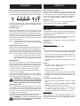
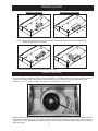
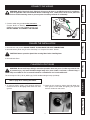
1
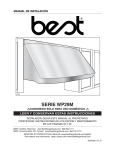
Use & Care / Installation Manual
Manual de Uso y Cuidado / Instalación
English / Español
Models / Modelos 233.5817*, 233.5818*
Kenmore Elite
Range Hood
®
Campana de cocina
* = color number, número de color
SV07328 rev. D
Sears Brands Management Corporation,
Hoffman Estates, IL 60179 USA
www.kenmore.com
www.sears.com
TM
READ AND SAVE THESE INSTRUCTIONS
TABLE OF CONTENTS
KENMORE LIMITED WARRANTY
Warranty .........................................................................2
Safety Instructions ..........................................................3
Operation ........................................................................4
Cleaning ...........................................................................4
Parts Included With Hood .............................................5
Parts Not Included With Hood .....................................5
Tools Needed For Hood Installation ............................5
Equivalent Duct Length Chart .......................................6
Install Ductwork ..............................................................7
Prepare The Hood Location ..........................................7
Prepare The Hood....................................................... 8-10
Install The Hood .............................................................10
Connect The Wiring .......................................................11
Finalize The Installation .................................................11
Changing Light Bulbs .....................................................11
Service Parts ....................................................................12
When this appliance is installed, operated and
maintained according to all supplied instructions,
the following warranty coverage applies. To arrange
for warranty service, call 1-800-4-MY-HOME®
(1-800-469-4663).
• For one year from the date of purchase, any
part of this product that fails due to a defect in
material or workmanship will receive free repair or
replacement if repair proves impossible. The length
of this coverage does not apply to the finish of any
painted or bright metal part.
• For thirty days date of purchase, any painted or
bright metal part of this product will be replaced
free of charge if its finish is defective in material or
workmanship.
All warranty coverage is void if this product is ever
used for other than private household purposes.
This warranty covers only defects in material and
workmanship, and will NOT pay for:
1. Consumable parts that can wear out from normal
use, including but not limited to filters, belts, light
bulbs, and bags.
2. A service technician to instruct the user in correct
product installation, operation or maintenance.
3. A service technician to clean or maintain this product.
4. Damage to or failure of this product if it is not
installed, operated or maintained according to the
all instructions supplied with the product.
5. Damage to or failure of this product resulting from
accident, abuse, misuse or use for other than its
intended purpose.
6. Damage to or failure of this product caused by the
use of detergents, cleaners, chemicals or utensils
other than those recommended in all instructions
supplied with the product.
7. Damage to or failure of parts or systems resulting from
unauthorized modifications made to this product.
Disclaimer of implied warranties; limitation of remedies
Customer’s sole and exclusive remedy under this
limited warranty shall be product repair as provided
herein. Implied warranties, including warranties of
merchantability or fitness for a particular purpose,
are limited to one year or the shortest period allowed
by law. Sears shall not be liable for incidental or
consequential damages. Some states and provinces
do not allow the exclusion or limitation of incidental or
consequential damages, or limitation on the duration
of implied warranties of merchantability or fitness, so
these exclusions or limitations may not apply to you.
This warranty gives you specific legal rights, and you
may also have other rights which vary from state to
state.
Sears Brands Management Corporation,
Hoffman Estates, IL 60179
2
SAFETY INSTRUCTIONS
! INTENDED FOR DOMESTIC COOKING ONLY !
CAUTION !
1. For indoor use only.
2. For general ventilating use only. Do not use to exhaust
hazardous or explosive materials and vapors.
3. To avoid motor bearing damage and noisy and/or
unbalanced impellers, keep drywall spray, construction
dust, etc. off power unit.
4. Your hood motor has a thermal overload which
will automatically shut off the motor if it becomes
overheated. The motor will restart when it cools down.
If the motor continues to shut off and restart, have the
hood serviced.
5. For best capture of cooking impurities, the bottom of
the hood should be at a minimum distance of 24” and
a maximum of 30” above the cooking surface.
6. To reduce the risk of fire and to properly exhaust air on a
ducted installation, be sure to duct air outside - Do not
exhaust air into spaces within walls or ceiling or into attics,
crawl spaces, or garage.
7. This product is equipped with a thermostat which
may start blower automatically. To reduce the risk
of injury and to prevent power from being switch on
accidentally, switch power off at service panel and
lock or tag service panel.
8. Because of the high exhausting capacity of this hood,
you should make sure enough air is entering the house
to replace exhausted air by opening a window close
to or in the kitchen.
9. Use with approved cord-connection kit only.
10. Please read specification label on product for further
information and requirements.
3
Service Parts
TO REDUCE THE RISK OF A RANGE TOP GREASE FIRE:
1. Never leave surface units unattended at high settings.
Boilovers cause smoking and greasy spillovers that may
ignite. Heat oils slowly on low or medium settings.
2. Always turn hood ON when cooking at high heat or
when flambeing food (i.e.: Crêpes Suzette, Cherries
Jubilee, Peppercorn Beef Flambé).
3. Clean ventilating fans frequently. Grease should not
be allowed to accumulate on fan, filters or in exhaust
ducts.
4. Use proper pan size. Always use cookware appropriate
for the size of the surface element.
1. SMOTHER FLAMES with a close-fitting lid, cookie
sheet, or metal tray, then turn off the burner. BE
CAREFUL TO PREVENT BURNS. If the flames do not
go out immediately, EVACUATE AND CALL THE FIRE
DEPARTMENT.
2. NEVER PICK UP A FLAMING PAN - You may be burned.
3. DO NOT USE WATER, including wet dishcloths or
towels - This could cause a violent steam explosion.
4. Use an extinguisher ONLY if:
A. You know you have a Class ABC extinguisher and
you already know how to operate it.
B. The fire is small and contained in the area where it
started.
C. The fire department is being called.
D. You can fight the fire with your back to an exit.
*Based on “Kitchen Fire Safety Tips” published by NFPA.
Installation
TO REDUCE THE RISK OF INJURY TO PERSONS IN THE
EVENT OF A RANGE TOP GREASE FIRE, OBSERVE THE
FOLLOWING*:
Cleaning
TO REDUCE THE RISK OF FIRE, ELECTRIC SHOCK, OR
INJURY TO PERSONS, OBSERVE THE FOLLOWING:
1. Use this unit only in the manner intended by the
manufacturer. If you have questions, contact the
manufacturer at the address listed in the warranty.
2. Before servicing or cleaning unit, switch power off at
service panel and lock the service disconnecting means
to prevent power from being switched on accidentally.
When the service disconnecting means cannot be
locked, securely fasten a prominent warning device,
such as a tag, to the service panel.
3. Installation work and electrical wiring must be done by
a qualified person(s) in accordance with all applicable
codes and standards, including fire-rated codes and
standards.
4. Sufficient air is needed for proper combustion and
exhausting of gases through the flue (chimney) of fuel
burning equipment to prevent backdrafting. Follow the
heating equipment manufacturer’s guideline and safety
standards such as those published by the National
Fire Protection Association (NFPA), and the American
Society for Heating, Refrigeration and Air Conditioning
Engineers (ASHRAE), and the local code authorities.
5. When cutting or drilling into wall or ceiling, do not
damage electrical wiring and other hidden utilities.
6. When performing installation, servicing or cleaning
the unit, it is recommended to wear safety glasses and
gloves.
7. Do not use this range hood with any additional solid
state speed control device.
8. Ducted fans must always be vented to the outdoors.
9. To reduce the risk of fire, use only metal ductwork.
10. This unit must be grounded.
11. When applicable local regulations comprise more
restrictive installation and/or certification requirements,
the aforementioned requirements prevail on those of
this document and the installer agrees to conform to
these at his own expenses.
Operation
WARNING
Safety
WARNING
Warranty
READ AND SAVE THESE INSTRUCTIONS
OPERATION
OPERATION
Always turn ON your hood before you begin cooking in
order to establish an air flow in the kitchen. Let the blower run
for a few minutes to clear the air after you turn off the range.
This will help keep the whole kitchen cleaner and brighter.
Filter maintenance indicator
After 24 hours of operation, the filter maintenance light
indicator will start blinking. This indicates the filters need
to be cleaned in order to maintain efficient operation of
the unit. The indicator light will blink until the function is
reset by pressing the nightlight switch for 3 seconds.
HC0049
Nigthlight switch
Press this switch once to turn on the nightlight. Press this
switch once more to shut off the nightlight.
1
2
3 4 5
1. Blower Auto OFF switch 4. Filter maintenance indicator
2. ON/OFF Blower speed switches 5. Nightlight switch
3. Halogen lights switch
Auto OFF switch
When a speed is selected, press the Auto OFF switch to
activate the delay function. The corresponding speed
indicator LED will start flashing to indicate this function is
activated. The fan will continue to operate for 5 minutes
and will stop automatically. To cancel the delay function,
press the Auto OFF switch once again; the blower will then
work in normal mode.
NOTE: The blower speed can be increased - or decreased during Delay mode without starting another
5-minute cycle.
ON/OFF Blower speed switches
Press the switch corresponding to the desired blower speed.
The light over the switch indicates the selected speed (from 1
for low speed to 4 for high speed). To turn off the blower,
press once more on the corresponding blower speed switch.
NOTE: When speed 1 is chosen, the blower will operate
at high speed for less than one second and then
revert back to speed 1. This operation is normal
and is designed for optimal blower performance.
HEAT SENTRY™
Your hood is equipped with a HEAT SENTRY thermostat.
This thermostat is a device that will turn on or speed up the
blower if it senses excessive heat above the cooking surface.
The light indicator over speed 3 switch will quickly flash.
1) If blower is OFF - it turns blower ON to speed 3.
2) If blower is ON at a lower (or higher) speed setting - it
turns blower to speed 3.
When the temperature level drops to normal, the blower
will return to its original setting and the light indicator
over speed 3 switch will stop flashing.
WARNING: The HEAT SENTRY thermostat can
start the blower even if the hood is turned OFF. If
this occurs, press the speed 3 switch until its light
indicator stops flashing if you must stop the blower.
Halogen lights switch
This switch provides 3 different lighting levels, according
to your needs. The lighting intensity changes by increments
of 1 (e.g.: Press once for low intensity, once again to get
more, up to three times). From the higher intensity, press
once again to shut off the lights.
Uses 120 Volts, 50 W, MR 16 with GU10 base or PAR 16
with GU10 base, shielded halogen bulbs (included).
WARNING: In order to prevent the risk of
personal injury, do not install a lamp identified
for use only in enclosed fixtures.
4
CLEANING
Grease filters
The grease filters and the bottom panel should be cleaned
frequently. Use a warm detergent solution. Grease filters
are dishwasher safe.
Wash more often if your cooking style generates greater
grease - like frying foods or wok cooking.
Remove filters by pulling latch tabs and rotating filters
downward.
Hood Cleaning
Stainless steel cleaning:
How to maintain its “BRIGHT LOOK”
Do:
- Regularly wash surfaces with clean cloth or rag soaked
with warm water and mild soap or liquid dish detergent.
- Always clean in the direction of original polish lines.
- Always rinse well with clear water (2 or 3 times) after
cleaning. Wipe dry completely.
- You may also use a specialized household stainless steel
cleaner.
Do not:
- Use any steel or stainless steel wool or any other
scrapers to remove stubborn dirt.
- Use any harsh or abrasive cleaners.
- Allow dirt to accumulate.
- Let plaster dust or any other construction residues
reach the hood. During construction/renovation, cover
the hood to make sure no dust sticks to stainless steel
surface.
Avoid when choosing a detergent:
- Any cleaners that contains bleach will attack stainless
steel.
- Any products containing: chloride, fluoride, iodide,
bromide will deteriorate surfaces rapidly.
- Any combustible products used for cleaning such
as acetone, alcohol, ether, benzol, etc., are highly
explosive and should not be used close to a range.
Enamel Finish:
Clean with warm water and mild detergent only. If
discoloration occurs, use a good enamel polish such as
automotive polish. (DO NOT use rough abrasive cleaner
or porcelain cleaner).
PARTS NOT INCLUDED WITH HOOD
NOTE
Before proceeding to the installation, check the contents
of the box. If items are missing or damaged, contact the
manufacturer.
Ducting Accessories are not included with hood.
(See “Equivalent Duct Length Chart” on page 6 for Ducting
Accessory Model Nos.)
Warranty
PARTS INCLUDED WITH HOOD
120 V, 50 W, MR16 with GU10 base or PAR 16
with GU10 base, shielded halogen lamps
(4 per hood). Sears Part No. SV05921
HR0012
Safety
Grease Filter
(2 per hood)
HR0010
Operation
3¼” x 10”
Adapter/Damper
HR0011
HR0041
Parts Bag including:
1 Wire Clamp LP16-AP
2 Wire Connectors no. 74B
5 no. 8 x 1/2” Screws
3 no. 6 x 1/2” Screws
Cleaning
TOOLS NEEDED FOR HOOD INSTALLATION
HR0045
HR0050
HR0043
Screwdriver
(Robertson or
Phillips)
Pencil
Duct Tape
Tape
Measure
Installation
HR0044
HR0047
Wire
Stripper
HR0049
Drill
HR0048
Sabre -or- Keyhole
Saw
Saw
5
Service Parts
HR0051
EQUIVALENT DUCT LENGTH CHART
Kenmore range hoods are designed to perform efficiently when attached to long runs of duct. As a point of reference,
this hood will function at approximately 80% of its rated air performance when 100 equivalent feet of 7” round
ductwork is attached. Use this chart to calculate the equivalent duct length of your system.
Broan Model 428
3¼” x 10”
Right-angle Elbow
Equivalent length
8.5 ft.
HJ0058
Sears Model 59691
6” Round Wall Cap
Equivalent length
34 ft.
(6 ft. w/o damper)
HA0085
HJ0048
Broan Model 401
Straight Duct
3¼” x 10” x 2’ long
Equivalent length
2 ft.
Broan Model 429
3¼” x 10”
Right-angle
Flat Elbow
Equivalent length
24 ft.
Broan Model 647
7” Round Wall Cap
Equivalent length
34 ft.
(6 ft. w/o damper)
HA0085
HJ0050
Broan Model 406
Straight Duct
6” round x 2’ long
Equivalent length
2 ft.
HJ0059
HA0037
Broan Model 430
3¼” x 10”
Right-angle
Short Eave Elbow
Equivalent length
15 ft.
HJ0060
Sears Model 59391
3¼” x 10” Wall Cap
Equivalent length
45 ft.
(7 ft. w/o damper)
HJ0050
Broan Model 407
Straight Duct
7” round x 2’ long
Equivalent length
2 ft.
HJ0049
HJ0049
HJ0056
Broan Model 419
6” Round Elbow
Equivalent length
8 ft.
Broan Model 415
7” Round Elbow
Equivalent length
10 ft.
HA0086
Broan Model 431
3¼” x 10”
Right-angle
Long Eave Elbow
Equivalent length
15 ft.
HJ0061
Sears
Model 59091
Roof Cap
(accepts 7” round
or 3¼” x 10” duct)
Equivalent length
30 ft.
(7 ft. w/o damper)
Sears Model “Ducting Accessories” available by calling Sears at:
1-800-4-MY-HOME®
Broan Model “Ducting Accessories” available by calling Broan at:
1-800-558-1711
Sears Model 59581
3¼” x 10” to 6”
Round Transition
Equivalent length
5.5 ft.
Broan Model 412H
3¼” x 10” to 7”
Round Transition
Equivalent length
5.5 ft.
HJ0057
6
INSTALL DUCTWORK
Roof cap
Warranty
1. Plan where and how the ductwork will be located.
Install proper-sized ductwork, transition(s), elbow(s), and roof or wall cap. For best results, use a minimum number
of transitions and elbows. Use 2’’ metal foil duct tape to seal duct joints.
The minimum hood distance above cooktop must not be less than 24’’. A maximum of 30’’ above cooktop is
highly recommended for best capture of cooking impurities.
Distances over 30’’ are at the installer and users discretion.
Roof cap
3¼” x 10” duct
Wall
cap
Wall
cap
Hood
Safety
6” OR 7”
round duct
Transition
3¼” x 10” to 6” OR
3¼” x 10” to 7”
Hood
24” minimum above
cooking surface
24” minimum above
cooking surface
Operation
HH0056A
HH0057A
INSTALLATION WITH
RECTANGULAR DUCT
INSTALLATION WITH
ROUND DUCT
PREPARE THE HOOD LOCATION
Cleaning
CABINET BOTTOM
1”
1. If the bottom of the cabinet is recessed, attach three
1” wide wood strips (not included), as shown beside, in
order to properly attach the hood to the cabinet. The
wood strips must be as thick as the recess.
10⅛’’
1”
1¾”
1”
1¾”
HD0026A
HORIZONTAL DISCHARGE
VERTICAL DISCHARGE
CABINET BOTTOM
Installation
2. Cut-out the openings for duct (A) and power cable (B), in cabinet or wall, according to the direction or discharge
chosen. See figures below.
CL
A
CL
1½”
2”
3½”
5/16”
HD0162A
5¼”
B 2¾”
5¼” 5¼” 1½”
dia.
7/8”
HD0163A
7
3/4”
5¼”
B
2”
Service Parts
1½”
4”
A
PREPARE THE HOOD
1. Punch-out the knock-out for the chosen opening (horizontal at the back or vertical on top of the hood) and for
electrical connection.
VERTICAL DISCHARGE
HORIZONTAL DISCHARGE
HD0164
HD0165
2. Pull latch tab and remove both filters from the hood.
HD0166
SCREW
LOCATIONS
3. Remove the 5 screws retaining the bottom panel to the
hood and set aside. Pull out the bottom panel by the
front part.
HD0167
8
PREPARE THE HOOD
Warranty
4. Unplug both light connectors mounted on each side panels.
See picture beside.
Safety
HE0075
6. Then lift the front of the side
panel.
7. Pull out the side panel tabs (B)
from the hood and remove the
side panel.
Cleaning
A
Operation
5. To remove side panel, hold it
near the front of the hood and
slide in the same direction as
the small arrow (A) in order to
disengage it.
Installation
B
HO0080
HO0081
HO0079
Service Parts
9
PREPARE THE HOOD
VERTICAL DISCHARGE
HORIZONTAL DISCHARGE
1
1
HO0084
HO0082
8. Using 2 no. 6 x 1/2’’ screws, assemble the adapter/damper to the hood.
NOTE: Damper flap pivot (1) to the front of the hood for vertical discharge and for horizontal discharge,
damper flap pivot to top of hood.
HO0083
HO0085
9. Seal the adapter/damper to the hood using duct tape.
INSTALL THE HOOD
1. Run power cable to installation location. Position the hood in its intended location. Using a pen, mark the position
of the screws (smaller part of the keyhole, see picture below for the 5 keyhole locations). Remove the hood.
Install 4 no. 8 x 1/2’’ screws, leaving a 1/8’’ gap. Do not install the no. 5 screw yet.
1
5
2
4
3
HD0168
2. Attach the wire clamp, insert the power cable in the hood and tighten the wire clamp to secure the cable. Place the
hood under the cabinet and slide it in position. Make sure the adapter/damper assembly enters the duct opening.
Tighten the 4 screws completely, then add the last screw (screw no. 5) in the center keyhole. Make sure the damper
flap opens freely.
10
CONNECT THE WIRING
Safety
1. Connect cable using provided wire connectors.
Connect BLACK to BLACK, WHITE to WHITE and
GREEN or bare wire under GREEN ground screw.
DO NOT FORGET TO CONNECT THE GROUND.
Warranty
WARNING: Risk of electrical shock. Electrical wiring must be done by qualified personnel in accordance
with all applicable codes and standards. Before connecting wires, switch power off at service panel and
lock service disconnecting means to prevent power from being switched on accidentally.
HE0059
FINALIZE THE INSTALLATION
!
CAUTION: Remove protective plastic film covering filters before installing them.
Operation
1. Reinstall both side panels. DO NOT FORGET TO PLUG BACK THE LIGHT CONNECTORS!
2. Reinstall bottom panel using 5 screws from Step 3 of “Prepare The Hood’’ Section.
3. Reinstall both filters.
!
WARNING: Do not touch lamps during or soon after operation. Burns may occur. In order to prevent the risk
of personal injury, only install shielded halogen lamps. Also, never install a cool beam, a dichroïc lamp, a
lamp not suitable for use in recessed luminaires or identified for use in enclosed fixtures.
Cleaning
CHANGING LIGHT BULBS
This hood requires 120 V, 50 W, MR16 type, GU10 shielded halogen lamps (included).
Refer to page 12 for ordering information.
2. Install the new lamps by placing the bulb leads into
their grooves in the socket and gently push upwards
and turn clockwise until secure.
Installation
1. To remove lamps, gently push upwards and turn
counterclockwise to disengage bulb leads from their
grooves.
Service Parts
HE0077
HE0076
11
SERVICE PARTS
1
3
2
10
9
6
7
4
REPLACEMENT PARTS AND REPAIRS
In order to ensure your unit remains in good
working condition, you must use the manufacturer
genuine replacement parts only. The manufacturer
genuine replacement parts are specially designed
for each unit and are manufactured to comply
with all the applicable certification standards
and maintain a high standard of safety. Any third
party replacement part used may cause serious
damage and drastically reduce the performance
level of your unit, which will result in premature
failing. The manufacturer recommends to contact
a certified service depot for all replacement parts
and repairs.
5
HL0064
KEY NO. PART NO.
1
SV13296
SV16571
2
SV16572
SV07322
3
SV07323
4
SV16569
5
SV05921
6
SV01766E
7
SV06111
SV07332
8
SV07333
9
SV07325
10
SV02160
*
SV09428
*
SV07326
*
SV07328
*
SV06751
*Not illustrated.
8
Order replacement parts by PART NO., not by
KEY NO.
DESCRIPTION
30’’ WIDTH 36’’ WIDTH
Adapter/Damper
1
1
Electronic Control Module, Black (including Overlay, item 3)
1
1
Electronic Control Module, White (including Overlay, item 3)
1
1
Overlay Black
1
1
Overlay White
1
1
Lamp Shell, Socket & Trim Ass’y
4
4
Halogen Lamp (50 W, 120 V, PAR 16, GU-10)
4
4
Motor (including Wheel, item 7)
1
1
Wheel
1
1
Filters with latch, square pressed, 9.92” x 17.98” x 0.35”
2
1
Filters with latch, square pressed, 12.92” x 17.98” x 0.35”
1
2
Transformer
1
1
Capacitor
1
1
Kenmore Elite Logo
1
1
Harness
1
1
Kenmore Elite Installation Manual
1
1
Installation Bag: 1 Wire Clamp LP16-AP, 2 Wire Connectors no. 74B,
1
1
5 no. 8 x 1/2” Screws, 3 no. 6 x 1/2” Screws
12
Get it fixed, at your home or ours!
Your Home
For troubleshooting, product manuals and expert advice:
www.managemylife.com
For repair – in your home – of all major brand appliances,
lawn and garden equipment, or heating and cooling systems,
no matter who made it, no matter who sold it!
For the replacement parts, accessories and
owner’s manuals that you need to do-it-yourself.
For Sears professional installation of home appliances
and items like garage door openers and water heaters.
1-800-4-MY-HOME®
(1-800-469-4663)
Call anytime, day or night (U.S.A. and Canada)
www.sears.com
www.sears.ca
Our Home
For repair of carry-in items like vacuums, lawn equipment,
and electronics, call anytime for the location of your nearest
Sears Parts & Repair Service Center
1-800-488-1222 (U.S.A.)
www.sears.com
1-800-469-4663 (Canada)
www.sears.ca
To purchase a protection agreement on a product serviced by Sears:
1-800-827-6655 (U.S.A.)
1-800-361-6665 (Canada)
Para pedir servicio de reparación
a domicilio, y para ordenar piezas:
Au Canada pour service en français:
1-888-SU-HOGAR®
(1-888-784-6427)
www.sears.com
1-800-LE-FOYER MC
(1-800-533-6937)
www.sears.ca
® Registered Trademark / TM Trademark of KCD IP, LLC in the United States, or Sears Brands, LLC in other countries
® Marca Registrada / TM Marca de Fábrica de KCD IP, LLC en Estados Unidos, o Sears Brands, LLC in otros países
MC
Marque de commerce / MD Marque déposée de Sears Brands, LLC