1
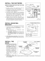
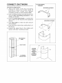
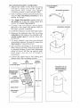
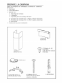
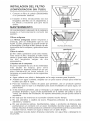
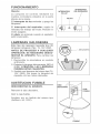
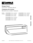
E
L
an
l
T
e
use & Care / installation Manual
pana
Manual de uso y cuidado /instalaci6n
Models
Modelos
233.52303200
233.52363200
(3o" wide / 76,2 cm de ancho)
233.52423200
(42" wide/106,7
(36" wide/91,4
cm de ancho)
cm de ancho)
0
J
u
m
t_
0
Sears, Roebuck and Co,, Hoffman Estates, HL60179 U,S,A,
www,sears,com
WARNING
SUITABLE
COOKING
WARNING
FOR
AREA.
USE
IN
HOUSEHOLD
TO REDUCETHE RISK OF FIRE, ELECTRICAL
SHOCK, OR INJURY TO PERSONS, OBSERVE
THE FOLLOWING:
1. Use this unit only in the manner intended by
the manufacturer. If you have questions, corn
tact the manufacturer
at the address or tele_
phone number listed in the warranty.
2. Before servicing or cleaning unit, switch power
off at service pane! and lock service panel to
prevent
power from being switched
on
accidentally. When the service disconnecting
means cannot be locked, securely fasten a
prominent warning device, such as a tag, to
the service panel.
3. Installation work and electrical wiring must be
done by a qualified person(s) in accordance
with all applicable codes and standards, including fire=rated construction
codes and stare
dards.
4. Sufficient air is needed for proper combustion
and exhausting of gases through the flue (chim_
ney) of fuel burning equipment to prevent
backdrafting.
Follow the heating equipment
manufacturer's
guidelines and safety stare
dards such as those published by the National
Fire Protection Association (NFPA), and the
American Society for Heating, Refrigeration
and Air Conditioning Engineers (ASHRAE), and
the local code authorities.
5. When cutting or drilling into wail or ceiling, do
not damage electrical wiring and other hidden
utilities.
6. Ducted fans must always be vented to the outdoors.
7. Do not use this unit with any solid=state speed
control device.
8. To reduce
ductwork.
the
risk of fire,
use only
steel
OF A RANGE
TOP
9. This unit must be grounded.
TO REDUCE THE
GREASE FIRE:
RISK
A. Never leave surface units unattended at high settings.
Boilovers cause smoking and greasy spillovers that
may ignite. Heat oils slowly on lowor medium settings.
B. AIwaysturn hood ON when cooking at high heat or
when cooking flaming foods.
C. Clean ventilating fans frequently. Grease should not
be allowed to accumulate on fan or filter.
D. Useproper pansize.Always use cookware appropriate
for the size of the surface element.
TO REDUCE THE RtSK OF INJURY TO PERSONS IN THE EVENT
OF A RANGE TOP
GREASE FIRE, OBSERVE THE FOLLOWING:*
1. SMOTHER FLAMES with a close=fitting lid,
cookie sheet, or metal tray, then turn off the
burner. BE CAREFULTO
PREVENT BURNS.
If the flames do not go out immediately, EVACU=
ATE AND CALLTRE FIRE DEPARTMENT.
2. NEVER PICK UP A FLAMING
be burned.
PAN =You may
3. DO NOT USE WATER, including wet dishcloths
or towe!s =vio!ent steam explosion will result.
4. Use an extinguisher ONLY" if:
A. You know you have a C!ass ABC extim
guisher and you already know how to op=
erate it.
B. The fire is small and contained in the area
where it started.
C. The fire department is being called.
D. "You can fight the fire with your back to an
exit.
* Based on "Kitchen
lished by NFPA.
Fire Safety Tips" pub=
CAUTION
1. To reduce risk of fire and to properly exhaust air,
be sure to duct air outside. Do not vent exhaust
air into spaces within wails or ceilings or into
attics, crawl spaces, or garages.
2. Take care when
detergents.
using
cleaning
agents
or
3. Avoid using food products that produce flames
under the Range Rood.
4. For general ventilating use only. Do not use to
exhaust hazardous or explosive materials and
vapors.
5. To avoid motor bearing damage and noisy and/
or unba!anced impellers, keep drywa!l spray,
construction dust, etc. off power unit.
6. Your hood motor has a thermal over!oad which
will automatically shut off the motor if it becomes
overheated.The motor will restart when it cools
down. If the motor continues to shut off and
restart, have the hood serviced.
7. For best capture of cooking impurities, the
bottom of the hood should be a minimum of 24"
and a maximum of 30" above the cooking sur=
face.
8. Two installers are recommended because of the
large size and weight of this hood.
9. Please read specification !abel on product for
further information and requirements.
PREPARE
THE HOOD
Unpack hood and check contents_
You should receive:
1 - Hood
1 - Decorative Flue Assembly
1 - Parts Bag containing:
1 - Mounting Bracket
1 - Discharge Collar
1 - Flue Mounting Bracket
8 - Mounting Screws (4,8 x 38mm Pan Head)
5 - Mounting Screws (3,9 x 9,Smm Pan Head)
8 - Drywall Anchors
1 - Installation Instructions
MOUNTING
BRACKET
DECORATIVE
FLUE
_
_
SCREWS (3,9 x
9,Smm
Pan Head)
5 MOUNTING
COLLAR
ISCHARGE
t;
FLUE MOUNTING
BRACKET
8 MOUNTING SCREWS
(4,8 x 38mm Pan Head)
8 DRYWALL
ANCHORS
INSTALL THE DUCTWORK
NOTE: To reduce the risk of fire, use only
metal ductwork,
ROUND
1. Decide where the ductwork will run
between the hood and the outside.
2. A straight, short duct run will allow the hood
to perform most efficiently.
3. Long duct runs, elbows, and transitions
wilI reduce the performance of the hood.
Use as few of them as possible. Larger
ducting
may be required
for best
performance with longer duct runs.
4. install a roof or wall cap. Connect round
metal ductwork to cap and work back towards hood location. Use duct tape to seal
the joints between ductwork sections.
@
=BOW
24" TO 30" ABOVE
COOKING SURFACE
!\
_D
6"
ADAPTER
INSTALL MOUNTING
BRACKET
FRAMING BEHIND DRYWALL
1= Construct wood wall framing that is flush
with interior surface of wail studs.
Make sure:
a) the framing
is centered
over
installation location.
b) the height of the framing wilI allow the
mounting bracket to be secured to
the framing within the dimensions
shown.
2. Afterwall surface is finished secure mounting bracket to framing using dimensions
shown.
INSTALL THE
HOOD
1. Hang the hood from the
bracket
through
the
rectangular cut-out on
the back of the hood.
Cut-out is larger than the
bracket
to allow for
horizontal adjustment.
The bottom of the hood
should be 24" to 30"
above
the cooking
,
38oi/16"=
bottom
of
hood
24"
above
eooktop
44o1/16"=
bottom
of
hood
30"
above
eooktop
MOUNTENG
SCREWS
WALL FRAMING
MOUN_NG
SCREWS
y'°
MOUN_NG
BRACKET
RECTANGULAR
CUTOUT
surface.
2. Secure the hood with
mounting screws. Use dr fwalI anchors, provided, if wall studs or framing are
not available.
MOUNT THE PLATE
Mount the plate of the electricaI system
attaching it with 3 screws,
PLATE OF
ELECTF_AL
SYSTEM
WIRING
Note: This range hood must be properly
grounded.The
unit shoumd be installed by
a qualified electrician in accordance with
all appHcabme national and mocalelectricam
codes.
GROUNDING INSTRUCTIONS
This appliance must be grounded, In the
event of an electrical short circuit, grounding
reduces the risk of electric
shock by
providing an escape wire for the electric
current, This appliance is equipped with a
cord having a grounding
wire with a
grounding plug, The plug must be plugged
into an outlet that is properly instaIled and
grounded,
WARNING - Improper grounding can result in a risk of electric shock,
ConsuIt a qualified electrician if the grounding instructions are not completely
understood, or if doubt exists as to whether the appliance is properly grounded,
Do not use an extension cord, If the power supply cord is too short, have a qualified
eIectrician install an outlet near the appliance,
Set the electrical power supply within the space covered by the decorative flues,
Position the power socket at a maximum distance of 33-7/16" (85 cm) from where
the Iead exits from the hood (see ilIustration aiongside), Make sure this does not
interfere with the bracket fastening area or with the decorative flue (where the flue
touches the wall),
Fit the plug into the power socket,
CONNECT
DUCTWORK
FLUE
MOUNTtNG
BRACKET
Ducted Configuration
1. Adjust the width of the flue mounting
bracket to equal the inside width of
decorative
flue. insert and tighten
mounting screws to hold bracket width.
2. Use mounting screws and wall anchors to
secure flue mounting
bracket to the
ceiling as shown.
3. Use 6" round metal duct to connect the
duct collar on the hood to the ductwork
above.
4. Use duct tape to make alI joints secure
and air tight.
5. Insert the decorative flues setting them on
the hood.
6. Extend the upper ftue to the ceiling and
secure with two mounting screws.
DECORATIVE
FLUE
j
DUCTTAPE
6"ROUND
METALDUCT
FASTEN
FLUETO
UPPER
BRACKET
WrrH
MOUNTING
SCREWS
MOUNTENG SCREWS
MOUNTING SCREWS
Nomductedrecirculation Configuration
1. Adjust the width of the flue mounting
bracket to equal the inside width of
decorative
flue. insert and tighten
mounting screws to hold bracket width.
2. Use mounting screws and wall anchors to
secure flue mounting
bracket to the
ceiling as shown.
3. Turn upper flue section upside down so
air vents are at the top. Slide upper flue
section into mower flue section.
4. Connect the non-ducted
recirculation
plenum to the upper flue section with (4)
fiat-head screws (supplied).
5. Install the reduction on the discharge collar.
6. Measure the distance from the top of the
reduction to the ceiling. Cut a iength of 5"
round metal duct 5" shorter than this
dimension.
7. Fit duct section over the non-ducted
recirculation plenum. For best fit, make sure
duct seam is toward the front.
FLUE MOUNTING
BRACKET
MOUNTENG SCREWS
MOUNTING SCREWS
8. Set duct/flue assembly on hood with top
tilted away from wall Reach around flue
to engage bottom of duct with discharge
collar On hood. TiNtflue up against wall.
Duct seam can be cut to length if
necessary.
9. Extend the upper flue to the ceiling and
secure with two mounting screws.
UPPER
FLUE SECTION
AIR
VENTS
(nnupper Je sectnon)
UPPER
BRACKET=
FASTEN FLUE TO
UPPER BRACKET
WiTH MOUNTING
SCREWS
FLUE SECTION
METAL DUCT
COLLAR
NON°DUCTED
RECmRCULATmON
mNSTALLATmON
FILTER
1. Purchase a charcoal filter (B03300488)
from your dealer.
2. InstalI the filter by pressing the 2 tabs on
the filter down into the speciaI housing and
rotating upward.
FILTER
MAINTENANCE
Proper maintenance of the Range Hood wilI
assure proper performance of the unit.
Grease Filters
The grease filters should be cleaned frequently. Use a warm detergent solution.
Grease filters are dishwasher safe.
GREASE FILTERS
Remove filter by pushing filter towards the
back of hood and rotating filter downward.
Charcoal Filter
The charcoal filter should be changed every
6 months. To remove the fiiter press inward
on the clamp and rotate the filter downward
until the 2 tabs can be removed from the
housing.
Hood Cleaning
Stainless steel is one of the easiest materiaIs
to keep clean. Occasional care will help preserve its fine appearance.
Cleaning tips:
, Hot water with soap or detergent is all that is usually needed.
,FoIIow alI cleaning by rinsing with clear water. Wipe dry with a clean, soft cloth to
avoid water marks.
, For discolorations or deposits that persist, use a non-scratching household cteanser
or stainless steel polishing powder with a little water and a soft cloth.
, For stubborn cases, use a plastic scouring pad or soft bristle brush together with
cleanser and water. Rub lightly in direction of polishing lines or "grain" of the
stainless finish. Avoid using too much pressure which may mar the surface.
,, DO NOT allow deposits to remain for long periods of time.
*, DO NOT use ordinary steel wool or steel brushes. Small bits of steel may adhere
to the surface causing rust.
,, DO NOT allow salt solutions, disinfectants, bleaches, or cleaning compounds to
remain in contact with stainless steel for extended periods. Many of these com e
pounds contain chemicals which may be harmfui. Rinse with water after exposure and wipe dry with a clean cloth.
Painted surfaces should be cleaned with warm water and mild detergent only.
OPERATION
UGHT
SWrrCH
Controls
The hood is operated using the slide controls
under the bottom of the hood.
BLOWER
SWrrCH
PILOT
LAMP
The light switch turns the lamps on and off.
The blower
switch :makes it possible to
select the motor operating speed. Position 0:
motor off.
01
The pilot mamplights up whenever the blower
is on.
HALOGEN
BULBS
This range hood requires two halogen buibs
(Type T4, 12V, 20W)+
ALWAYS SWITCH OFFTHE ELECTRICITY
SUPPLY BEFORE CARRYING OUT ANY
OPERATIONS ON THE APPLIANCE.
To change bulbs:
1. Loosen the ring nut by turning
it
counterclockwise+
2. Remove the bulb by pulling sideward(DO
NOT ROTATE).CAUTION: BULB MAY BE
HOT!
3+ Replace with Type T4, 12V, 20W ha!ogen
bulb+ Do not touch replacement butb with
bare hands!
FUSE
REPLACEMENT
SWITCH OFFTHE ELECTRiCiTY SUPPLY.
DECORATIVE
FLUE
Remove the decorative flue+
Open the fuse box+
Replace with the same type of fuse (5x20mm,
4A, 125V)+
FUSE
23
WARRANTY
Hfwithin 1 year from the date of installation, any part of this range hood fails to
function properIy due to a defect in material or workmanship, Sears will repair
the part or furnish and install a new part, free of charge.
FULL 30_DAY WARRANTY ON F_NtSH ON PAINTED OR BRIGHT METAL
PA RTS
Hfwithin 30 days from the date of instaiIation, the finish on any painted or bright
metal parts of this range hood is defective in material or workmanship, Sears
wiII furnish and install a new part, free of charge.
WARRANTY SERVICE _S AVAILABLE BY CONTACTING THE NEAREST
SEARS SEVICE CENTER/DEPARTMENT
JNTHE UNITED STATES.
This warranty appiies onty whiIe this product is in use in the United States= This
warranty gives you specific IegaI rights and you may have other rights which
vary from state to state.
Sears, Roebuck and Co., Dept 817WA, Noffman Estates, IL 60179
INDICADO
PARAELUSOENCOCINASPARA EVlTAR EL RIESGO DE
DOMESTICAS.
PERSONAS EN CASO DE FUEGO
PARA EVlTAR EL RIESGO
DE iNCENDIO,
CORTOCIRCUITO
O DAI_O
PARA
LAS
PERSONAS,
OBSERVE ATENTAMENTE
LAS
SIGUIENTES NORMAS:
1. Use esta unidad solamente de lamanera indicada por
elfabricante; si tiene dudas, p6ngase en contacto con
@tea la direcci6n o tel6fono indicados en la garant[a.
2. Antes de hacer una revisi6n o de limpiar la unidad,
descon@tela de la red para evitar que se enciendade
manera accidental.En elcaso de que @te no puedaser
desactiovado,seindicar_en la placade caracteoristicas.
3. El montaje y la instalaci6n el@trica debe hacerlos un
t@nico especializadosiguiendo las normasest_ndar e
induyendo aquellas de construcci6n anti incendio.
4. Necesita airesuficientepara unaapropiada combusti6n
y escape de gases a trav6s deltubo del dep6sito de
quemade combustible.Paraevitarqueelhumo aspirado
vuelva a la cocina, siga las directivas delfabricante y
las normas est_ndar de siguridad asfcomo las normas
puMicadaspor laAsociaci6nde prevenci6nde incendios
(NFPA)y la Socieodad americana de especialistas en
caleofacci6n,refrigeraci6ny aireacondicionadoy ademas
las normas de las autoridades locales.
5. Hacer un corte o un tabdro en lapared o en eltecho no
debe da_ar la instalaci6nel@trica u otras instalaciones
ocultas en la pared.
6. Los conductos ventiladoresdeben siempre desalojaral
exterior.
7. No use esta unidad con dispositivo de control de la
velocidad a estado s61ido.
8. Para evitar el riesgo de incendio, use solamente
conductos de metal.
9. Esta unidadtiene que ser conectada atierra.
PARA EVITAR EL RIESGO DE FUEGO POR ALTO
NIVEL DE GRASA:
A.
B.
C.
D.
Nunca abandone los quemadores con elfuego alto.
Lacccci6n causahumoy restosde grasa que pueden
arder. Caliente elaceite a fuego medio o bajo.
Endenda siempre lacampana cuandococine a fuego
alto o cuando cocine alimentos facilmente
inflamables.
Limpie con frecuencia los ventiladores. No se debe
acu mular grasa en el ventilador o en el filtro.
Usa eltama_p de cazuela apropiado. Use siempre
utensilios decocina de tamaF_oymaterial adecuados.
NIVEL DE GRASA,
SIGUIENTE:*
TENGA
DANOS
A
POR ALTO
EN CUENTA LO
1. SOFOQUE LALLAMA con unatapadera apropiada,una
bandeja metbJica 6 un utensilio de coc[na qu.epueda
cubrirla, despues, @ague el quemador. ACTU ECON
PRECAUCION PARA EVlTAR QUEMAoDURAS. Si la
llamanose extingueinmediaotamente,SALGAY LLAME
A LOS BOMBE-ROS.
2. NUNCACOJA UNA SARTEN ENLLAMAS, porquecorre
elriesgo de quemarse.
3. NO USEAGUA ni pa_osotoallas hOmidasporque puede
provocarse unaviobnta humareda.
4. Use un extintor SOLAMENTE si:
A.
B.
C.
D.
Posee un extintor de clase ABC y sabe
perfectamente c6mo usarlo.
EIfuegoes pequdioyest_ controbdo en el mismo
sitio en que empez6.
Ha Ilamado con anterioridad a los bomberos.
Puede combatir elfuego retrocediendo hacia la
salida.
* Basadoen"Seguridadantifuegoenlaccc[na"publicado
porNFPA.
ADVERTENCIA
1. Para reducir el riesgo de incendios y para evacuar
correctamenteloshumos,asegurarsede haberrealizado
una conducci6n del aire hasta el exterior. No expulsar
los humos en espacios cerrados pot paredes otechos,
aticos, espacios angostos o garajes.
2. Prestar la m_xima atenci6n al utilizar productos de
limpieza o detergentes.
3. Evitar el uso de productos alimentarios que puedan
inflamarse bajo la campana.
4. S61opara ventilaci6n total. No use gases de escape
peligrosos o materiales y vapores explosivos.
5. Para evitar daFlos en el funcionamiento del motor e
impulsores ruidosos y/o desequi librados, mantenga
alejades de la unidad de encendido pulverizadores en
seco o polvo.
6. El motortiene unnivelde sobrecargat@micaque apaga
automaticamente el motor cuando se ha recalentado
excesivamente. El motor se pone de nuevo en
fincionamento cuando latemperatura baja. Si el motor
comienza a encenderse y a apagarse, deberb_hacer
una revisi6n de 6ste.
7. Para limpiar mejor las impurezas al cocinar, la parte
inferior de la campana debe estar a unatemperatura
minimade 24 gradosy mb_ximade 30 gradosper debajo
de latemperature de la zona de cocci6n.
8. Debido a su gran tamale y peso, se recomienda su
montaje por parte de dos t@nicos esperializados.
9. Se recomienda leer la placa de caracteoristicas del
produdo para ulteriorinformaci6n.
PREPARE
LA CAMPANA
Sacar la campana de I'embalaje y controlar el contenido.
Recivireis:
1 - Campana
1 - Tubo decorativo
1 - Bolsita con:
1 - Soporte de montaje
1 - CasquilIo
1 - Soporte para e! montaje de! tubo
8 - Tornillos de montaje (4,8 x 38mm cabeza redonda)
5 - Tomillos de montaje (3,9 x 9,5ram cabeza redonda)
8 - Escarpias
1 - Instrucciones para instalaci6n
SOPORTE DE
MONTAJE
MONTAJE
(3,9
X 9,5ram
5 TORNILLOS
redonda)
TUBO
DECORATIVO
_
cabeza
DE
CASQUILLO
SOPORTE PARA EL
MONTAJE DEL TUBO
8 TORNILLOS DE
MONTAJE (4,8 x 38ram
cabeza redonda)
8 ESCARPIAS
mNSTALACION
EXTRACCION
DEL TUBe
DE
URIERTA DEL
TEJADO
\
NOTA: para evitar el riesge de incendio,
TURO
use seiamente material de metal
1. Decida donde va a colocar e! tube de
extracci6n entre Ia campana y Ia parte
exterior.
2. Un recorrido de tubo corto y recto
permitira a la campana funcionar de
manera mAs eficaz.
3. Los recorridos largos de tube, codes y
manguitos
impiden
eI
buen
funcionamiento de la campana. Use e!
menor nOmero de ellos posible. Para
uses prolongados es necesario un tube
6" (15cm)
de evacuaci6n
del aire de mayor
ADAPTADOR
diAmetro.
4. Instale una cubierta 6 una tapa. Una el
tubo de metal a la cubierta y retroceda hasta la posici6n de la campana. Use
une cinta para precintar Ias juntas entre las partes del entubado.
mNSTALACmON SOPORTE
MONTAJE
DE
ESTRODTO.A/
DE MADERA
EN LA PARED
1. Construya una estructura
de madera
en la pared que quedara nivelada con Ia
parte interior de Ios tacos en la pared=
AsegOrese de que:
a) La estructura se encuentra centrada
per encima de Ia instalaci6n det tubo.
b) La altura de la estructura permite fijar el
soporte de montaje en esta estructura
siguiendo las dimensiones indicadas.
2. Una vez que la superficie de la pared
este acabada
sujete eI soporte de
montaje siguiendo
las dimensiones
indicadas.
mNSTALACION DE
LA CAMPANA
/_zone
38q/16"(96,7cm)=siladistanciaentrela
carnpanaylazonadecocci6nesde24"(61cm)
44q/16"(111,9cm)
= si la distancia entre la
campana y la zona de cocci6n es de 30" (76cm).
ESTRUCTURA
TORNILLOS
MONTAJE
DE MADERA
EN LA PARED
DE
TORNILLOS DE
1. Cuelgue la campana deI
MONTAJE
soporte per el agujero
rectangulare
situado
detr_s de Ia campana. El
DE
_
MONTAJE
agujero es m&s grande
j_
que el soporte
para
permitir el ajuste en
horizontal.
La parte inferior de Ia
AGUJE_O
RECTANGULARE
campana debe estar a
una distancia de 24"
(61cm) 6 30" (76cm) pot
encima de la zona de cocci6n.
2. Suiete la campana con tomiHos de reontaje. Use escarpias incluidos en el
equipamiento si no dispone de tacos o de la estructura de soporte en madera.
INSTALACION
DE LA PLACA
Montar Ia placa deI sistema electrico fij_ndoJa
mediante tres tornillos.
INSTALACION
_
i
PLACA DEL
S_STEMA
ELECTR_O
ELECTRICA
Nota: Este tipo de campana tiene que set
conectada
a tierra cuidadosamenteo
La
unidad
debe inetamarla un tecnico
electricista
siguiendo
mas norrnas
nacionalee y locales,
INSTRUCCIONES
DE CONEXION
A
TERRA
Este aparato se debe conectar a tierra. En
caso de cortocircuito, la conexi6n a tierra
reduce eI riego de electrocuci6n ya que
posee un hilo de descarga a tierra para Ia
corriente. Este aparato est_ equipado con
un cable que posee un hilo de toma de tJerra
con una clavija de tierra. La clavija se debe
conectar
a un
enchufe
instalado
correctamente y conectado a tierra.
ADVERTENCIAuna conexi6n a tierra incorrecta puede provocar riesgos de
electrocuci6n.
ConsuIte a un electricista calificado si no se entienden o sJ existe alguna duda
sobre Ia correcta conexi6n a tJerra.
No utilice un cabIe de prolongaci6n. Si et cabIe proporcionado es demasJado
corto, p6ngase en contacto con un electricista calificado para que instale un
enchufe cerca del aparato.
Conecte la alimentaci6n electrica en et espacio cubierto per el tubo decoratJvo.
Coloque el enchufe a una distancia m4xima de 33-7/16" (85 cm) desde e! cable de
la campana (vease figura adjunta). Aseg0rese de que no interfiera con el &rea de la
abrazadera de suieci6n o con el tube decorative (donde el tube decorative toca con
la pared).
Conecte la clavija al enchufe.
ENTUBADO
DE
CANAUZACmON
SOPORTE DE
MONTAJE [}EL TUBO
TORNILLOS DE
MONTAJE
Conf!guraci6n con tubo
1. Regule el soporte de montaje del tube
de manera que su ancho coincida con el
de! tubo decorativo superior. CoIocar y
fijar los tornillos de montaje para que el
soporte se adapte a dicho ancho.
2. Use tornillos y escarpias para fijar aI techo
eI soporte de montaje demtubo come se
indica.
3, Use un tube de metal de 6" (15cm) de
di_metro para unit el casquillo que se
encuentra encima de Ia campana al tube
de extracci6n situado arriba.
4. Use cinta para ajustar todas las junturas y
que quede hermetico.
5. Introduzca
eI
tubo
decorative
conectAndolo en Ia campana.
6. Extienda Ia parte superior
del tube
decorativo hacia e! techo y suj6tela con
2 tornillos de montaje.
TORNILLOS
DE MONTAJE
TUBO
DECORATIVO
CINTA
TUBO DE
METAL DE 6"
(15cM)DE
F_JE EL TUBO AL
SOPORTE CON
TORNILLOS DE MONTAJE
Configuraci6n sin tubo
1. Regule el soporte de montaje deI tube
de manera que su ancho coincida con el
deI tubo decorative superior. Co!ocar y
fijar los tomilIos de montaje para que el
soporte se adapte a dicho ancho.
2. Use tornillos y escarpias para fijar al techo
el soporte de montaje del tube come se
indica.
3. De Ia vuelta a la parte superior del tubo
de manera que las rejilas de salida del
aire esten en Ia parte superior. Haga
deslizar la parte superior del tube hasta
aIcanzar la parte inferior de este.
4. Una el respiradero de aire con Ia parte
superior det tubo per medio de cuatro
tornillos con cabeza plana (adjuntos).
SOPORTE DE
MONTAJE DEL TUBO
TORNtLLOS DE
MONTAJE
TORNILLOS
DE MONTAJE
5. Instale e! reductor en el collar de descarga.
6. Mida Ia distancia desde Ia parte superior
deI reductor hasta el techo. Corte a una
distancia de 5" (12,5 cm) a_rededor del
tubo de metal 5" m&s corte que su medida.
7. Instale el tube en el orificio. Para una mejor
instaiaci6n, asegurarse de que la juntura
demtubo se encuentre en la parte frontal.
8. Instale et tube en la campana con Ia parte
superior inclinada con respecto a Ia pared. Alargar el borde de! tubo para sujetarlo
a la parte inferior del tube mediante el collar de descarga en la campana. Inclinar
Ia parte superior del tube decorative contra la pared. La iuntura del tubo se
puede cortar iongitudinalmente si es necesario.
9. Extendienda Ia parte superior det
tube hacia el techo y sujetela con
REJILLAS
DE
2 tornilIos de montaie.
FUE EL TUBO AL
SOPORTE CON
TORNILLOS DE MONTAJE
mNSTALACmON DEL FJLTRO
(CONFJGURACJON
SIN TUBO)
1. Compre un filtro al carb6n (B03300488)
a su proveedor habitual.
2. Instalen el filtro Jntroduciendo Ias dos
JengOetas del filtro en el alojam[ento a
tal efecto y haciendo que gire hacia
arriba.
RLTROAL
MANTENJMJENTO
Un mantenlmiento adecuado de Ia campana
asegura el funcionamlento
correcto deJ
aparato.
Fi#ros antigrasa
Los fimtroe antigrasa
deben limplarse a
menudo. Use un detergente que no sea
fuerte. El filtro antigrasa se puede meter en
el Iavava]JlJas.Extraiga el filtro tlrando de etlo
hacia atr&s de Ia campana y gir#_ndoloshacia
abajo.
Filtro M carb6n
E! filtro debe cambiarse cada seis meses.
Para sacar el filtro, empu]en el reten hacia
dentro y giren hacia abajo eJfiltro hasta que
las dos
lengQetas
salgan
de sus
aIojamientos.
Mmpieza de la campana
El acero inoxidable es uno de los meteriaJes
m&s f&cJles de Iimpiar,
pero ser[a
aconsejable un especiaI cuidado en su uso
para mantenerJa
en buen estado.
La
campana se puede Iimpiar de Jas siguientes
FILTROS ANTIGRASA
LENGOETAS
maneras:
® Agua caJiente con ]ab6n o detergente es la mejor manera para Iimpiada.
® Act&rela con agua corriente, sequela con un patio suave y limpio para evitar las
hueIlas que de]a eI agua.
® Para las manchas o restos de grasa que persistan, use un producto quimico
domestico que no raye 6 un limpJador para acero inoxidable con poca agua y un
patio suave.
® S[ las manchas persisten, use un estropajo y un cepil!o de cerdas suaves con un
producto limpiador y agua. Frote suavemente en el sentido del puJido o de las
"vetas" del remate del inoxidable. No apriete demasiado porque podr[a datiar la
superficie.
® No de]e que las manchas se acumuJen durante mucho tiempo.
® No use utensilJos o cepilJos de acero. Pequetias particulas de acero pueden
adherirse y oxidarse.
® No use soluciones salinas, desinfectantes, Iejias, o productos de Iimpieza que
permanezcan en contacto con el acero inoxidable durante largos periodos de
tiempo. Muchos de estos productos contienen componentes qu[micos que podr[an
resultar nocivos. AcIare con agua y seque con un patio Iimpio.
Las superficies Jacadas deben limpiarse soJamente con agua tibia y detergente no
muy fuerte.
FUNCmONAMIENTO
Mandos
La campana se controla
mediante
Ios
mandos corrrederos situados en la parte
inferior de Ia misma.
El interruptor
I_mparas.
ENTERRUPTOR
DA LUZ
_NTERRUPTOR
DEL ASPERADOR
P_LOTO
da luz enciende y apaga las
,
El interruptor
del aspirader:
regula Ia
velocidad de trabajo del motor= Posici6n O:
motor apagado,
El piloto se enciende cuando el aspirador
estA funcionando,
LAMPARAS
/
i
)
°©
01
0123
HALOGENAS
Este tipo de campana necesita dos (2)
I&mparas hal6genas (Tipo T4, 12V, 20W).
ANTES DE PROCEDER A CUALQUIER
OPERACK3N, ES NECESARIO DESCONECTAR EL APARATO. Para cambiar las
IAmparas:
1_ Destornillar Ia abrazadera en sentido
antihorario.
ABR#ZADERA
2_ Extraiga la I&mpara oblicuamepte. NO LA
GRE. ATENCION:
LAS LAMPARAS
PUEDEN ESTAR CAUENTES,
3. Sustituir con I&mparas del mismo tipo (T4,
12V, 20W). No toque la I&mpara de
repuesto con las manos desnudas.
SUSTmTUCmON FUSIBLE
DESCONECTAR
_RJBO
DECORATIVO
EL APARATO.
Remover el tubo decorativo.
Abrir Ia caja fusible.
Sustituir pot un fusible
(5x20mm, 4A, 125V).
del mismo
tipo
\,
FUSEBLE
GARANTIA
Si dentro de 1 a_o de Ia fecha de Ia instalaci6n, cualquier parte de esta campana
de cocina deja de funcionar en forma apropiada debido a defecto en el material
o la mano de obra, Sears reparar_ la pieza afectada o proveera e instaiar_ una
9ieza nueva libre de cargo.
GARANTIA
COMPLETA
DE 30 BiAS EN EL ACABADO
EN PSEZAS
METAL_CAS PINTADAS O ABRILLANTADAS
Si dentro de 30 dfas de la fecha de ia instalaci6n, el acabado de cuaiquier
9arts met_lica pintada o abrillantada perteneciente a esta campana de cocina
aparece con defecto en el material o la mano de obra, Sears proveer_ e
instalar_ una pieza nueva libre de cargo.
EL SERVJCJO DE GARANTJA SE OBTIENE PONIE_NDOSE EN CONTACTO
CON EL CENTRO
DE SERVtCJO O DEPARTAMENTO
SEARS MAS
CERCANO EN LOS ESTADOS UNIDOS,
Esta garantia es valedera unicamente si este producto se tiene en uso dentro
de los Estados Unidos. Esta garant[a le confiere derechos bgabs especfficos
y Ud. puede tener adem_s otros derechos que vat[an de estado a estado.
Sears, Roebuck
and Co., Dept. 817WA, Hoffman
Estates,
tL 60179
SERVICE
MODELS
KEY NO.
9
14
16
19
26
45
48
49
53
6O
62
86
97
107
118
119
120
145
146
147
151
165
2O8
228
229
23O
234
238
241
274
332
4O7
474
477
PARTS
233.52303200 _ 233.52363200
PART NO,
B08087294
B02300233
BE3345170
B03295005
B02300722
BWO000019
B02310187
B03295076
B03202007
B02300249
B08091462
B08088378
BE3402883
B03202287
BE3344597
BE3343464
B08091367
B032920170
B032920180
BR2300132
B032920200
B03295008
B02300783
B08086252
B03201014
B03295075
B03295072
B03295074
B03295073
B03295035
B03295009
BE3344985
B02300791
B03295006
B06001991
B03300488
B08999634
B02300782
B02300674
* Not shown assembled.
= 233.52423200
DESCRiPTiON
Grease FiIter
Motor Capacitor
Electrica! Box Support
Terminal Box
Halogen Lamp Bulb
Blower
Motor
Blower Wheel
Rubber Washer
Feeder Cable
Blower Mounting Cover
Discharge collar
Blower Support
Wires Stop
Decorative Flue Bottom
Decorative Flue Top
FhJe Mounting Bracket
Feeder cable connection Box
Feeder Cable Connection Box Cover
Junction Clamp
Electrical Box Wires Stop
ControI Board Box
Transformer
Controls Board
Warning lamp
Switch Board Box Cover
ControI Board Box
Motor Switch Button
Light Switch Button
Fuse Box
Cover
Blower Support Bracket
Halogen Lamp Housing
Termina! Cover
Blower Assembly (hcludes Key Nos. 45, 48,
49, 53)
Non-ducted recirculation filter
Non-ducted recirculation KHT
Fuse
Fuse Holder
LISTA
DE PIEZAS
MODELOS
CODo No
9
14
16
19
26
45
48
49
53
6O
62
86
97
107
118
119
120
145
146
147
151
165
2O8
228
229
230
234
238
241
274
332
4O7
474
477
DE FiECAMBIO
233.52303200 - 233.52363200
PtEZA No
B08087294
B02300233
BE3345170
B03295005
B02300722
BWO000019
B02310187
B03295076
B03202007
B02300249
B08091462
B08088378
BE3402883
B03202287
BE3344597
BE3343464
B08091367
B032920170
B032920180
BR2300132
B032920200
B03295008
B02300783
B08086252
B03201014
B03295075
B03295072
B03295074
B03295073
B03295035
B03295009
BE3344985
B02300791
B03295006
B06001991
B03300488
B08999634
B02300782
B02300674
* Be encuentran por separado.
- 233.52423200
DESCRJPCI6N
Filtro antigrasa
Condensador
Soporte de Ia caja de instalaci6n electrica
Caja del cuadro electrico
L&mpara hal6gena
Convoyador
Motor
ManilIa de! motor
AImohadilIa antivibraziones
Cabos
Soporte motor
CasquilIo
Soporte convoyador
Sujeta cabos
Tubo decorativo inferior
Tubo decorativo superior
Soporte de montaje del tubo
Caja cabos alimentaci6n
Tapa de la caja cabos alimentaci6n
Terminal
Sujeta cabos
Caja de instalaci6n electrica
Trasformador
Base de los mandos
Piloto
Tapa de la caja mandos
Caja de los mandos
Mando motor
Mando iluminaci6n
Caja fusible
Tapa
Soporte convoyador
Caja de la I_mpara haI6gena
Tapa del cuadro electrico
Conjunto motor (HncJuyeJos N. 45, 48,
49, 53)
Filtro configuraci6n sin tubo
Equipo configuraci6n sin tubo
Fusible
Portafusible
SERVICE
MODELS
PARTS
233.52303200
- USTA
DE PIEZAS
- 233.52363200
DE RECAMBIO
o 233.52423200
86
332
16
/
119
B02300674
/
,.,
118
274
165
14
60
151
145
62
147
146
474 4_
26
407
107
229
230
238
234
241
228
97
_
_/
48
53
49
_pair of major brand applicances in your own home...
no matter who made it, no matter who sold it[
1-800-4-MY-HOME
®
Anytime, day or night
(1-800-469-4663)
(U.S.A. and Canada)
www.sears.com
www.sears.ca
For repair of carry-in products Iike vacuums, Iawn equipment, and
electronics, cail for the nearest Sears Parts and Repair Center.
!-800-488-!222
Anytime, day or night
For the replacement parts, accessories and owner's manuals
that you need to do-it-yourself, call Sears PartsDirectSM[
1-800-366-PART
6 a.m. - 11 p.m. 7 days a week
(1-800-366-7278)
(U.S.A. only)
www.sears.com/partsdirect
To purchase or inquire about a Sears Service Agreement
or Sears Maintenance Agreement:
!-800-827-6655
(U.S.A.)
7 a.m. - 5 p.m.
CST, Mon. - Sat.
Para pedir servicio de reparacidn a
domicilio, y para ordenar piezas:
1-888-SU-HOGAR sM
(1-888-784-6427)
1-800-361-6655
(Canada)
9 a.m. - 8 p.m. EST, M-F,
4 p.m. Sat.
Au Canada pour
service en frangais:
1-888-LE-FOYER Mc
(1-800-533-6937)
www.sears.ca
LHomeCenlral®J
© Scars, Roebuck and Co.
® Registered Trademark / "rM Trademark / SMService Mark of Sears, Roebuck and Co.
® Marca Rcgistrada / "rM Marca de F_brica / SMMarcade Serviciode Sears, Roebuckand Co.
McMarque de commerce / MDMarque d6pos6c de Sears, Roebuck and Co.
04306898


![PLAS A O ]-OR](http://vs1.manualzilla.com/store/data/005852706_1-5db0b7ed584537f0e62af161fb124638-150x150.png)