1
an
use & Care / Installation Manual
pana
cocina
Manual de uso y cuidado /instalaci6n
Models
Modelos
233.50303200
233.50363200
(3o" wide / 76,2 cm de ancho)
(36" wide/91,4
cm de ancho)
0
u
¢0
0
Sears, Roebuck and Co,, Hoffman Estates, HL60179 U,S,A,
www,sears,com
WARNING
SUITABLE
COOKING
WARNING
FOR
AREA.
USE
IN
HOUSEHOLD
TO REDUCETHE RISK OF FIRE, ELECTRICAL
SHOCK, OR INJURY TO PERSONS, OBSERVE
THE FOLLOWING:
1. Use this unit only in the manner intended by
the manufacturer. If you have questions, corn
tact the manufacturer
at the address or tele_
phone number listed in the warranty.
2. Before servicing or cleaning unit, switch power
off at service pane! and lock service panel to
prevent
power from being switched
on
accidentally. When the service disconnecting
means cannot be locked, securely fasten a
prominent warning device, such as a tag, to
the service panel.
3. Installation work and electrical wiring must be
done by a qualified person(s) in accordance
with all applicable codes and standards, including fire=rated construction
codes and stare
dards.
4. Sufficient air is needed for proper combustion
and exhausting of gases through the flue (chim_
ney) of fuel burning equipment to prevent
backdrafting.
Follow the heating equipment
manufacturer's
guidelines and safety stare
dards such as those published by the National
Fire Protection Association (NFPA), and the
American Society for Heating, Refrigeration
and Air Conditioning Engineers (ASHRAE), and
the local code authorities.
5. When cutting or drilling into wail or ceiling, do
not damage electrical wiring and other hidden
utilities.
6. Ducted fans must always be vented to the outdoors.
7. Do not use this unit with any solid=state speed
control device.
8. To reduce
ductwork.
the
risk of fire,
use only
steel
OF A RANGE
TOP
9. This unit must be grounded.
TO REDUCE THE
GREASE FIRE:
RISK
A. Never leave surface units unattended at high settings.
Boilovers cause smoking and greasy spillovers that
may ignite. Heat oils slowly on lowor medium settings.
B. AIwaysturn hood ON when cooking at high heat or
when cooking flaming foods.
C. Clean ventilating fans frequently. Grease should not
be allowed to accumulate on fan or filter.
D. Useproper pansize.Always use cookware appropriate
for the size of the surface element.
TO REDUCE THE RtSK OF INJURY TO PERSONS IN THE EVENT
OF A RANGE TOP
GREASE FIRE, OBSERVE THE FOLLOWING:*
1. SMOTHER FLAMES with a close=fitting lid,
cookie sheet, or metal tray, then turn off the
burner. BE CAREFULTO
PREVENT BURNS.
If the flames do not go out immediately, EVACU=
ATE AND CALLTRE FIRE DEPARTMENT.
2. NEVER PICK UP A FLAMING
be burned.
PAN =You may
3. DO NOT USE WATER, including wet dishcloths
or towe!s =vio!ent steam explosion will result.
4. Use an extinguisher ONLY" if:
A. You know you have a C!ass ABC extim
guisher and you already know how to op=
erate it.
B. The fire is small and contained in the area
where it started.
C. The fire department is being called.
D. "You can fight the fire with your back to an
exit.
* Based on "Kitchen
lished by NFPA.
Fire Safety Tips" pub=
CAUTION
1. To reduce risk of fire and to properly exhaust air,
be sure to duct air outside. Do not vent exhaust
air into spaces within wails or ceilings or into
attics, crawl spaces, or garages.
2. Take care when
detergents.
using
cleaning
agents
or
3. Avoid using food products that produce flames
under the Range Rood.
4. For general ventilating use only. Do not use to
exhaust hazardous or explosive materials and
vapors.
5. To avoid motor bearing damage and noisy and/
or unba!anced impellers, keep drywa!l spray,
construction dust, etc. off power unit.
6. Your hood motor has a thermal over!oad which
will automatically shut off the motor if it becomes
overheated.The motor will restart when it cools
down. If the motor continues to shut off and
restart, have the hood serviced.
7. For best capture of cooking impurities, the
bottom of the hood should be a minimum of 24"
and a maximum of 30" above the cooking sur=
face.
8. Two installers are recommended because of the
large size and weight of this hood.
9. Please read specification !abel on product for
further information and requirements.
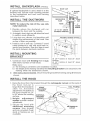
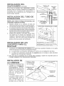
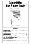
mNSTALL BACKBPLABH
_oPT,o.AL_
ROOF CAP
If optional backspiash is used, attach it to the
finished wail, Secure hood mounting bracket
to the backsplash and omit wail framing
described below,
mNSTALL THE
DUCTWORK
6"ROUND
DECORATIVE
FLUE
HOOD
NOTE: To reduce the risk of fire, use only
metal ductwork,
1, Decide where the ductwork will run
between the hood and the outside,
2, A straight, short duct run will allow the hood
to pedorm most efficientiy,
3, Long duct runs, eibows, and transitions will
reduce the performance of the hood, Use
as few of them as possible,
4, Install a roof or waEIcap, Connect 6" round
metal ductwork to cap and work back towards hood location, Use duct tape to seaI
the joints between ductwork sections,
24"TO
30"ABOVE
COOKING
/
SURFACE
FRAMING
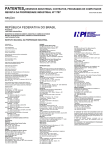
mNSTALL MOUNTmNG
BRACKET
BEHIND
DRYWALL
)p
36 3/4"=
bottom
of hood
24'* above
cooktop
1, Construct wood wall framing that is flush
42 3/4"= bottom of hood 30" above
with interior sudace of wail studs,
cooktop
Make sure:
a) the framing is centered over installation location,
b) the height of the framing will allow the mounting bracket to be secured to the
framing within the dimensions shown,
2, After wailsurface is finished, secure mounting bracket to framing using dimensions
shown,
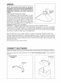
mNSTALL THE HOOD
1= Hang the hood from the bracket through the rectangular
the hood, Cut-out
is
larger than the bracket to
allow
for horizontal
adjustment, The bottom of
the hood should be 24"
to 30" above the cooking
surface,
2= Height
adjustment
screws provide vertical
adjustment,
3, Secure the hood with
additionam
mounting
screws=
Use drywalI
anchors, provided, if wall
studs or framing are not
avaiIable=
cut-out on the back of
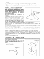
WIRING
Note: This range hood must be properly
grounded.The unit eheumd be installed by a
qualified electrician in accordance with aH
applicable
nationam and local electricam
codes.
GROUNDING iNSTRUCTiONS
This appliance must be grounded, in the
event of an electrical short circuit, grounding
reduces the risk of ebctric shock by providing
an escape wire for the electric current. This
appliance is equipped with a cord having a
grounding wire with a grounding plug. The
plug must be plugged into an outlet that is
properly installed and grounded.
WARNING - improper grounding can result in a
Consult a qualified electrician if the grounding
understood, or if doubt exists as to whether the
Do not use an extension cord. if the power supply
electrician install an outlet near the appliance.
risk of electric shock.
instructions are not completely
appliance is properly grounded.
cord is too short, have a qualified
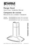
Set the electrical power supply within the space covered by the decorative flues.
Position the power socket at a maximum distance of 33-7/16" (850 mm) from where
the Iead exits from the hood (see illustration alongside). Make sure this does not
interfere with the bracket fastening area or with the decorative pipe (where the flue
touches the wall).
Fit the plug into the power socket.
CONNECT
DUCTWORK
Adjust the width of the flue mounting bracket using screws (A) indicated in Figure.
Use screws (B) and wall anchors to secure flue mounting
shown.
FLUE _,_OUNT_NG
BRACKElr
bracket to the ceiling as
SCREWS B
SCREWS A
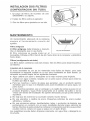
Ducted Configuration
1. Use 6" round metal duct to connect the
duct collar on the hood to the ductwork
above.
2. Use duct tape to make all joints secure
and air tight.
3. Insert the decorative flues setting them on
the hood.
4. Extend the upper flue to the ceiling and
secure with the 2 screws (C).
DECORATIVE
FLUE
/DUCTTAPE
-, FASTEN
_,_"
"-
FLUE TO
UPPER BRACKET
WITH SCREWS (C)
6"ROUND
METALDUCT
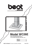
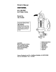
Ductfree Configuration
1. Turn upper flue sect{on upside
down so air vents are at the top.
Slide upper flue section into
lower flue section.
2. Connect the duetfree pienum to
the upper flue section with (4) flathead screws (supplied).
3. InstalI the reduction
on the
discharge collar.
4. Measure the distance from the
top of the reduction to the ceiling.
Cut a length of 5" round metam
duct
5" shorter
than this
dimension.
5. Fit duct section over the ductfree
plenum. For best fit, make sure
duct seam is toward the front.
UPPER
FLU E SECTION
X
AIR
VENTS
(nn upper
UPPER
BRACKET
fUue section)
[
DUCTFREE
PLENUM ....
FLUE SECTION
5"
METAL DUCT
D_SCNARGE
COLLAR
6. Set duct/flue assembly on hood
with top tilted away from wall.
Reach around flue to engage
bottom of duct with discharge
collar on hood. Tilt flue up against wall. Duct seam can be cut to length if necessary.
7. Extend the upper flue to the ceiling and secure with the 2 screws (C).
DUCTFREE
FILTER
INSTALLATION
1. Ductfree filter kit (B03300487) is included.
2. Position the filters over the blower.
3. Rotate to lock filters in place.
- DUCTF'REE
F_LTERS
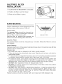
MAINTENANCE
Proper maintenance of the Range Hood wilI
assure proper performance of the unit.
Grease Filter
The grease fiBter should be cteaned frequendy. Use a warm detergent solution.
Grease filter is dishwasher safe.
Remove filter by pushing filter towards the
back of hood and rotating filter downward.
Ductfree
GREASE FILTER
Filters
The ductfree fiiters should be changed every 6 months. Rotate the fiiters to remove
and replace.
Hood Cleaning
Stainless steel is one of the easiest materials to keep clean. Occasional care wilI help
preserve its fine appearance.
Cleaning tips:
,, Hot water with soap or detergent is all that is usually needed.
,, Follow all cleaning by rinsing with clear water. Wipe dry with a clean, soft cloth to
avoid water marks.
,, For discolorations or deposits that persbt, use a non-scratching household cleanser
or stainless steel polishing powder with a little water and a soft cloth.
,, For stubborn cases, use a plastic scouring pad or soft bristle brush together with
cleanser and water. Rub Iightly in direction of polishing lines or "grain" of the
stainless finish. Avoid using too much pressure which may mar the surface.
,, DO NO'[ allow deposits to remain for Iong periods of time.
,, DO NOT use ordinary stee! wool or steel brushes. Small bits of steel may adhere
to the surface causing rust.
,, DO NOT allow salt solutions, disinfectants, bleaches, or cleaning compounds to
remain in contact with stainless stee! for extended periods. Many of these compounds contain chemicals which may be harmful. Rinse with water after exposure and wipe dry with a clean cloth.
Painted surfaces shouid be cleaned with warm water and mild detergent only.
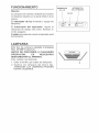
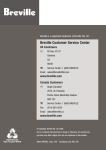
OPERATION
Controls
The hood is operated using the slide controls
under the bottom of the hood.
The light switch turns the lamps on and off.
The blower switch :makes it possible to select
the motor operating speed. Position O: motor
off.
The pilot mamplights up whenever the blower
is on.
LIGHT
BULBS
This range hood requires two 40-Watt light
bulbs (included).
ALWAYS SWITCH OFF THE ELECTRICITY
SUPPLY BEFORE CARRYING OUT ANY
OPERATIONS ON THE APPLIANCE.
To change bulbs:
1. Remove the screw securing the light fitting.
2. Replace with Hght bulbs of the same type+
CAUTION: BULB MAY BE HOT!
LIGHT
SWITCH
BLOWER
SWITCH
WARRANTY
Hfwithin 1 year from the date of installation, any part of this range hood fails to
function properIy due to a defect in material or workmanship, Sears will repair
the part or furnish and install a new part, free of charge.
FULL 30_DAY WARRANTY ON F_NtSH ON PAINTED OR BRIGHT METAL
PA RTS
Hfwithin 30 days from the date of instaiIation, the finish on any painted or bright
metal parts of this range hood is defective in material or workmanship, Sears
wiII furnish and install a new part, free of charge.
WARRANTY SERVICE _S AVAILABLE BY CONTACTING THE NEAREST
SEARS SEVICE CENTER/DEPARTMENT
JNTHE UNITED STATES.
This warranty appiies onty whiIe this product is in use in the United States= This
warranty gives you specific IegaI rights and you may have other rights which
vary from state to state.
Sears, Roebuck and Co., Dept 817WA, Noffman Estates, IL 60179
ADVERTENCIA
INDICADO
PARA
DOMESTICAS.
EL USO
EN
COCINAS
PARA EVITAR EL RIESGODE
JNCENDIO,
CORTOCIRCUITO
O DANO
PARA
LAS
PERSONAS,
OBSERVE ATENTAMENTE
LAS
SIGUIENTES NORMAS:
PARA
EVITAR
EL RIESGO
DE DANOS
A
PERSONAS EN CASO DE FUEGO POR ALTO
NIVEL DE GRASA, TENGA EN CUENTA LO
SIGUIENTE:*
1. SOFOQUE LA LLAMA con unatapadera apropiada,una
bandeja metbdica6 un utensilio de codna qu.epueda
cubrirla,de@ues, @ague el quemador. ACTUE CON
PRECAUCION PARA EVlTAR QUEMA@URAS. Si la
llamanose extingueinmedbotamente,SALGAY LLAME
A LOS BOMBE-ROS.
1. Use esta unidad solamente de la manera indicada por
el fabricante; si tiene dudas, p6ngase en contacto con
6ste a ladirecci6n o teldono indicadce en la garantia.
2. NUNCACOJA UNA SARTEN ENLLAMAS,porque corre
2. Antes de hacer una revisi6n o de limpiar la unidad,
elriesgo de quemarse.
descon6ctela de lared para evitar que se encienda de
manera accidental.Enelceso de que 6ste no puedaser 3. NO USEAGUA ni paPiceotoallas hOmidasporque puede
provocarseuna viobnta humareda.
desactiovado,se indicar_en laplace de caractedsticas.
4. Use un extintor SOLAMENTE si:
3. El montaje y la instalaci6n el@trica debe hacerlos un
A. Posee un extintor de clase ABC y sabe
t@nico especializado siguiendo las normas estandar e
perfectamente c6mo usarlo.
incluyendo aquellas de construcci6n anti incendio.
B. EIfuegoes peque_oyest_ controbdo en elmismo
4. Necesita airesuficientepara una apropiadacombusti6n
sitio en que empez6.
y escape de gases a tray@ del tubo del dep6sito de
quemade combustible.Paraevitarqueel humoaspirado
C. Ha Ilamado con anterioridad a los bomberce.
vuelva a la cocina, siga las directivas del fabricante y
D. Puede combatir elfuego retrocediendo hacia la
las normas est_ndar de siguridad ad como las normas
salida.
publicadaspor laAsociaci6nde prevenci6n de incendice
* Basadoen"Seguridadantifuegoen lacocha" publicado
(NFPA) y la Socieodadamericana de especialistas en
por NFPA.
cele@cci6n,refrigeracbny aireacondicionadoyademas
las normas de las autoridades locales.
5. Hacer un corte o untaladro en la pared o en eltecho no
debe da_ar la instalaci6nel@trice u otras instalaciones
ocultas en la pared.
6. Lce conductce ventiladoresdebensiempre desalojaral
exterior.
7. No use esta unidad con dispositivo de control de la
velocidad a estado s61ido
8. Para evitar el riesgo de incendio, use solamente
conductos de metal.
9. Esta unidad tiene que ser conectada atierra
PARA EVJTAR EL RIESGO DE FUEGO POR ALTO
NIVEL DE GRASA:
A.
B.
C.
[:1
Nunca abandone los quemadores con elfuego alto.
La cocci6nceusahumo y reetcede grasaque pueden
arder. Caliente el aceite a fuego medio o bajo.
Enciendasiempre lacampana cuando cocine afuego
alto o cuando cocine alimentos facilmente
inflamables.
Limpie con frecuencia los ventiladores. Nose debe
acumular grasa en el ventilador o en el filtro.
Usa eltama_p de cazuela apropiado. Use siempre
utensilicede cocina detamaF_oy materialadecuadce.
ADVERTENCIA
1. Para reducir el riesgo de incendice y para evacuar
correctamenteIcehumce,asegurarsede haberrealizado
una conducci6n delaire hasta el exterior. No expulsar
los humce en espacios cerradce pot paredes otechos,
_ticos, espacice angcetos o garajes.
2. Prestar la m_.xima atenci6n al utilizar productos de
limpiezao detergentes.
3. Evitar el uso de productos alimentarios que puedan
inflamarse bajo la campana.
4. S61opara ventilaci6n total. No use gases de escape
peligrosos o materiales yvapores explosivce.
5. Para evitar daF_osen el funcionamiento del motor e
impulsores ruidosos y/o desequi librados, mantenga
alejados de launidad de encendido pulverizadores en
seco o polvo.
6. El motortiene un nivelde sobrecargat@micaqueapaga
automaticamente el motor cuando se ha recalentado
excesivamente. El motor se pone de nuevo en
fincionamento cuando latemperatura baja. Si el motor
comienza a encenderse y a apagarse, deberb_hacer
una revisi6n de 6ste.
7. Para limpiar mejor las impurezas al cocinar, la parte
inferior de lacampana debe estar a unatemperatura
minimade 24 gradcey m_ximade 30 gradospor debajo
de latemperature de lazona de cocci6n.
8. Debido a su gran tama_o y peso, se recomienda su
montaje por parte de dos t@nicce esperializados.
9. Se recomienda leer la placa de caracteoristicas del
producto para ulterior informaci6n.
mNSTALACmON DEL
SALPICADERO
(OPCIONAL)
Si se usa un modelo con salpicadero, sujete
primero 6ste a la pared. Asegure los tomillos de
montaje de la campana al saJpicadero y
prescinda de Ia estructura de montaje en la
pared abajo descrita.
mNSTALACION
EXTRACCmON
DEL TUBO
TUBO
DECORATIVO
DE
_.
CAMPANA
NOTA: para evitar el riesgo de incendio, use
solamente material de metal
1. Decida donde va a colocar el tubo de
extracci6n entre lacampana y laparteexterior.
2. Un recorrido de tubo corte y recto permitir& a
la campana funcionar de manera m_s eflcaz.
3. Losrecorridoslargosdetubo,codosy manguitos
impiden elbuenfuncionamisnto de lacam pan&
UseeEmenor n0mero de ellosposible.
4. Instale una cubierta 6 una tap& Una el tubo
de metal de 6" (15cm) de di_metro a la
cubierta y retroceda hasta Ia posici6n de la
campana. Use une cinta para precintar las
juntas entre las pares del entubado.
mNSTALACmON DE LOS
36._,,4,,_93,_o=_:
s__d_s,_=o_,,
on,,_
_a
campana y la zona de coccion es de 24"(61 crn).
SOPO
42-3t4"(199cm}=
si la distancia
y l......
k) .....
RTES
PARA
EL
MONTAJE
d......
entre I.......
p.....
le30"(76cm).
1. Construya una estructura de madera en la pared que quedara nivelada con Ia parte
interiorde lostacos en Ia pared.Aseg0resede que:
a) La estructura se encuentra centrada per encima de la instaIaci6n del tube.
b) La altura de la estructurapermitefijar lossoportes para el montajeen esta estructura
siguiendo las dimensiones indicada&
2. Una vez que Ia superficie de Ia pared est6 acabada sujete los soportes para el
montaje siguiendo las dimensiones indicadas.
mNSTALACmON DE
LA CAMPANA
TORNILLO$
PARA
ESTRUCTURA
DE
MADERA
LA REGULACION
DE LA ALTURA
1. Cuelgue la campana deI
soporte pot el agujero
rectangumare
situado
detr_s de la campan& Et
agujero es m&s grande
que el soporte
para
permitir
el ajuste en
horizontal.
La parte inferior de Ia
campana debe estar a
una distancia de 24"
(61cm) 6 30" (76cm) per
encima de la zona de
TORNILLOS
PARA
MONTAJE
ADICIONALES
SOPORTE DE
MONTAJE
RECTANGULARE
EN
cocci6n.
2. Los tomilBos para la regu_aci6n de la aBtura permiten un ajuste en vertical.
3. Sujete la campana con torniHos para montaje adicionaBes. Use escarpias si no
dispone de tacos o de la estructura de soporte en madera.
mNSTALACION
ELECTRICA
Nota: Este tipo de campana tiene que set
conectada
a tierra cuidadosamente.
La
unidad
debe
instalarla
un tecnico
electricista
siguiendo
mas normas
nacionames y locales.
INSTRUCCIONES
DE CONEXI©N
A
TERRA
Este aparato se debe conectar a tierra. En
caso de cortocircuito, la conexi6n a tierra
reduce e! riego de electrocuci6n
ya que
posee un hilo de descarga a tierra para la
corriente. Este aparato estA equipado con
un cable que posee un hilo de toma de tierra
con una clavija de tierra. La claviia se debe
conectar a un enchufe instalado correctamente y conectado a tierra.
ADVERTENCIA* una conexi6n a tierra incorrecta puede provocar Hesgos de
electrocuci6n.
Consulte a un electricista calificado si no se entienden o si existe alguna duda
sobre Ia correcta conexi6n a tierra.
No utilice un cable de prolongaci6n. Si el cabie proporcionado es demasiado
corto, p6ngase en contacto con un eIectricista calificado para que instale un
enchufe cerca del aparato.
Conecte la alimentaci6n el6ctrica en el espacio cubierto pot et tubo decorativo.
Coioque el enchufe a una distancia maxima de 33-7/16" (85 cm) desde e! cable de
la campana (vease figura adjunta). AsegOrese de que no interfiera con el Area de la
abrazadera de suieci6n o con el tubo decorativo (donde el tubo decorativo toca con
la pared).
Conecte la claviia al enchufe.
ENTUBADO
DE CANAUZACmON
Regule Ia anchura dei tubo montando la abrazadera con los tornilios (A) como se
puede observar en Ia Figura.
Use tornilios y escarpias para fiiar al techo el
TORNILLOSB
soporte para el rnontaje demtubo como se
indica.
SOPORTE PARA EL
MONTAJE DELTUBO
TORNILLOS
A
Configuraci6n con tubo
1. Use un tubo de metam de 6" (15cm) de
di&metro para unir el collar de descarga
que se encuentra encima de la campana
aI tube de extracci6n situado arriba.
2. Use cinta para ajustar todas las ]unturas y
que quede hermetico.
3. htroduzca el tube decorative conectAndolo
en Ia campana.
4. Extienda
Ia parte superior
del tubo
decorativo hacia el techo y su]etela con 2
tornilIos (C).
o.
TUBO
LApA
RTE
_15cM)DE
DIAMETRO
Configuraci6n sin tubo
1. De Ia vuelta a la parte superior
deI tube de manera que Ias
rejiHae de salida del aire esten en
la parte superior. Haga deslizar Ia
parte superior del tube hasta
aIcanzar Ia parte inferior de este.
2. Una el respiradero de aire con la
parte superior del tubo por medio
de cuatro tomillos con cabeza
plana (adjuntos).
3. Instale et reductor en el colIar de
descarga.
4. Mida la distancia desde la parte
superior del reductor
hasta el
techo. Corte a una distancia de 5"
(12,5 cm) amrededor demtube de
metal 5" m_s corto que su medida.
5. Instale el tube en el orificio. Para
una mejor instalaci6n, asegurarse
de que Ia juntura del tubo se
encuentre en Ia parte frontal.
6. Instale e! tubo en la campana con
la parte superior inclinada con respecto a Ia pared. Alargar el borde deI tube para
su]etarlo a la parte inferior del tube mediante el co!lar de descarga en la campana.
Inclinar Ia parte superior del tube decorative contra Ia pared. La juntura del tube
se puede cortar Iongitudinalmente si es necesario.
7. Extendienda la parte superior del tube hacia el techo y sujetela con 2 tomillos
(C).
INSTALACION
(CONFIGURACION
DOS FILTROS
SIN TUBO)
1, El juego de filtros de ricamb[o
(B03300487) es adjunto,
de aire
2, InstaIe los filtros sobre el asp[rador,
3, Gire los fHtros para ajustarlos en su s[tio,
FILTROS
MANTENIMIENTO
Un mantenim[ento adecuado de Ia campana
asegura el funcionamJento
correcto
del
aparato,
Filtro antigrasa
El filtro antigrasa debe I[mpiarse a menudo,
Use un detergente que no sea fuerte,
FILTROANTIGRASA
EI filtro antigrasa se puede meter en eI
lavavajHlas, Extra[ga el f[Itro tirando de ello hac[a atr_is de la campana y g[r_indolos
hacia abajo,
Filtros (configuraci6n sin tubo)
Los filtros deben camb[arse cada seis meses, Gire los fHtros para desenroscaflos
camb[aflos,
y
Limpieza de la campana
E! acero [noxidable es uno de Ios meter[ales m&s fb,cHes de !impiar, pero ser[a
aconsejable un espec[aI cu[dado en su uso para mantenerla en buen estado, La
campana se puede I[mp[ar de Ias s[guientes maneras:
® Agua caliente con jab6n o detergente es la mejor manera para limpiada,
® AcI&rela con agua corfiente, sequela con un paso suave y Hmpio para evitar las
hueHas que de]a et agua,
® Para las manchas o restos de grasa que persistan, use un producto quire[co
domestJco que no raye 6 un HmpJador para acero [nox[dable con poca agua y un
paso suave,
® S[ las manchas persisten, use un estropajo y un cepillo de cerdas suaves con un
producto limpiador y agua, Frote suavemente en el sent[do del pul[do o de las
"vetas" del remate del inox[dabte, No apr[ete demas[ado porque podr[a daSar la
superficie,
® No deje que las manchas se acumulen durante mucho t[empo,
® No use utens[IJos o cepHIos de acero, PequeSas part[culas de acero pueden
adhefirse y oxidarse,
® No use soluc[ones sa!inas, desinfectantes, Iej[as, o productos de J[mp[eza que
permanezcan en contacto con et acero inoxidable durante largos per[odos de
t[empo, Muchos de estos productos contJenen componentes qu[m[cos que podr[an
resultar nocivos, Actare con agua y seque con un paso limp[o,
Las superficies Jacadas deben HmpJarsesolamente con agua tibia y detergente no
muy fuerte,
FUNCmONAMmENTO
La campana se controla mediante los mandos
corrrederos situados en la parte inferior de la
misma.
El interruptor
IAmparas.
INTEF_F_UPTOR
DA
Mandos
da luz enciende y apaga las
El interruptor
del aepirador:
regula Ia
ve!ocidad de trabajo del motor. Posici6n 0:
motor apagado.
Ei piBoto se enciende cuando el aspirador estA
funcionando.
LAMPARAS
Este tipo de campana necesita 2 lamparas
Tipo 40 WATT (adjuntos).
ANTES DE PROOEDER A CUALQUJER
OPERACtON,
ES
NECESARJO
DESCONECTAR EL APARATOo
Para cambiar GasI&mparas:
1. Quite el tornillo que sujeta Ias I&mparas.
2. Sustituir con I&mparas deI mismo tipo.
ATENCION: LAS LAMPARAS PUEDEN
ESTAR CALIENTES.
LUZ
INTERRUPTOR
DEL ASPIRADOR
GARANTIA
Si dentro de 1 a_o de Ia fecha de Ia instalaci6n, cualquier parte de esta campana
de cocina deja de funcionar en forma apropiada debido a defecto en el material
o la mano de obra, Sears reparar_ la pieza afectada o proveera e instaiar_ una
9ieza nueva libre de cargo.
GARANTIA
COMPLETA
DE 30 BiAS EN EL ACABADO
EN PSEZAS
METAL_CAS PINTADAS O ABRILLANTADAS
Si dentro de 30 dfas de la fecha de ia instalaci6n, el acabado de cuaiquier
9arts met_lica pintada o abrillantada perteneciente a esta campana de cocina
aparece con defecto en el material o la mano de obra, Sears proveer_ e
instalar_ una pieza nueva libre de cargo.
EL SERVJCJO DE GARANTJA SE OBTIENE PONIE_NDOSE EN CONTACTO
CON EL CENTRO
DE SERVtCJO O DEPARTAMENTO
SEARS MAS
CERCANO EN LOS ESTADOS UNIDOS,
Esta garantia es valedera unicamente si este producto se tiene en uso dentro
de los Estados Unidos. Esta garant[a le confiere derechos bgabs especfficos
y Ud. puede tener adem_s otros derechos que vat[an de estado a estado.
Sears, Roebuck
and Co., Dept. 817WA, Hoffman
Estates,
tL 60179
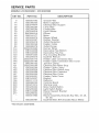
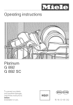
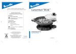
SERVICE
MODELS
KEY NO.
9
14
16
26
28
29
45
48
49
53
58
6O
86
114
118
119
120
122
145
146
147
151
152
165
165
167
168
195
196
228
229
238
241
4O7
477
PARTS
233.50303200 / 233.50363200
PART NO,
B08087292
B02300233
BE3244974
B02300264
B02300280
B03200618
BW0000019
B02310177
B03295076
B03202007
B03295018
B02300248
B08088378
B032904990
BE3343338
BE3343339
B08091335
B03295016
B032920170
B032920180
BR2300132
B032920200
B03292200
B03295029
B03295008
B03295030
B03295031
BE3343337
B02011113
B08086255
B03201014
B03295032
B03295033
BE3344985
B03295034
B06001983
B03300487
* Not shown assembled.
DESCRiPTiON
Grease Filter
Motor Capacitor
Electrical Box Support
Lamp Bulb
Lampholder
Light Diffuser
Blower
Motor
Blower Wheel
Rubber Washer
Outlet Reduction
Feeder Cable
Outlet FIange
Runner Wires
Decorative Flue Bottom
Decorative Flue Top
Flue mounting Bracket
Ductfree Plenum
Feeder cable connection Box
Feeder Cable Connection Box Cover
Junction Clamp
Electrical Box Wires Stop
Feeder Cable Clamp
Electrical Box Switch Assy=
ElectricaI Box Capacitor
Electrical Box Cover
Feeder Cable Cover
Bracket
Reflector
Controls Board
Warning lamp
Motor Switch Button
Light Switch Button
Blower Support Bracket
Closing
Blower Assembly dncludes Key Nos= 45,48,
49, 53)
Ductfree filters KIT dncludes Nos=2 fiIters)
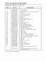
USTA
DE PIEZAS
DE RECAMBIO
MODEL OS 233.50303200 / 233. 50363200
COD. N°
9
14
16
26
28
29
45
48
49
53
58
6O
86
114
118
119
120
122
145
146
147
151
152
165
165
167
168
195
196
228
229
238
241
4O7
477
P_EZA N.
B08087292
B02300233
BE3244974
B02300264
B02300280
B03200618
BW0000019
B02310177
B03295076
B03202007
B03295018
B02300248
B08088378
B032904990
BE3343338
BE3343339
B08091335
B03295016
B032920170
B032920180
BR2300132
B032920200
B03292200
B03295029
B03295008
B03295030
B03295031
BE3343337
B02011113
B08086255
B03201014
B03295032
B03295033
BE3344985
B03295034
B06001983
B03300487
* Se encuentran pot separado.
DESCRJPCI6N
Filtro antigrasa
Condensador
Soporte de la caja de instalaci6n electrica
L_mpara
Soporte de Ia I_mpara
Tapa de Ia I_mpara
Convoyador
Motor
Manilla de motor
Almohadilla antivibraziones
Reducci6n
Cabos
Conector deI aire
Sujeta cabos
Tubo decorativo inferior
Tubo decorativo superior
Soporte de montaje deI tubo
Desviador de! aire
Caja cabos alimentaci6n
Tapa de la caja cabos alimentaci6n
Terminal
Sujeta cabos
Sujeta cabos
Caja de instalaci6n electrica
Caja de instalaci6n electrica
Tapa de Ia caja de instalaci6n electrica
Tapa cabos alimentaci6n
Soporte
Reflector
Base de Ios mandos
Piloto
Mando motor
Mando iluminaci6n
Soporte convoyador
Sierre
Conjunto motor dncluye los N. 45, 48,
49, 53)
Conjunto filtros configuraci6n sin tubo
(Incluye N.2 filtros)
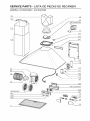
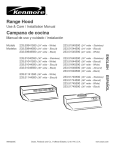
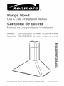
SERVICE
MODELS
PARTS
233.50303200
- USTA
DE PIEZAS
DE RECAMBIO
/ 233.50363200
t22
58
120
86
lift9
152
477
4O7
118
45
53
114
......
60
168
165
B03300487
_:41
229
238
(03295029)
228
167
28
qb,__
29
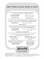
_pair of major brand applicances in your own home...
no matter who made it, no matter who sold it[
1-800-4-MY-HOME
®
Anytime, day or night
(1-800-469-4663)
(U.S.A. and Canada)
www.sears.com
www.sears.ca
For repair of carry-in products Iike vacuums, Iawn equipment, and
electronics, cail for the nearest Sears Parts and Repair Center.
!-800-488-!222
Anytime, day or night
For the replacement parts, accessories and owner's manuals
that you need to do-it-yourself, call Sears PartsDirectSM[
1-800-366-PART
6 a.m. - 11 p.m. 7 days a week
(1-800-366-7278)
(U.S.A. only)
www.sears.com/partsdirect
To purchase or inquire about a Sears Service Agreement
or Sears Maintenance Agreement:
!-800-827-6655
(U.S.A.)
7 a.m. - 5 p.m.
CST, Mon. - Sat.
Para pedir servicio de reparacidn a
domicilio, y para ordenar piezas:
1-888-SU-HOGAR sM
(1-888-784-6427)
1-800-361-6655
(Canada)
9 a.m. - 8 p.m. EST, M-F,
4 p.m. Sat.
Au Canada pour
service en frangais:
1-888-LE-FOYER Mc
(1-800-533-6937)
www.sears.ca
LHomeCenlral®J
© Scars, Roebuck and Co.
® Registered Trademark / "rM Trademark / SMService Mark of Sears, Roebuck and Co.
® Marca Rcgistrada / "rM Marca de F_brica / SMMarcade Serviciode Sears, Roebuckand Co.
McMarque de commerce / MDMarque d6pos6c de Sears, Roebuck and Co.
04306897