1
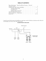
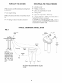
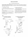
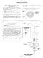
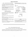
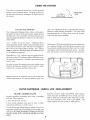
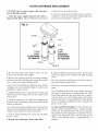
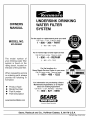
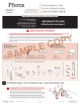
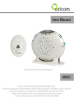
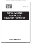
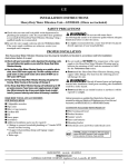
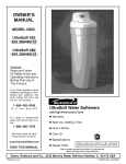
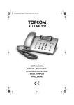
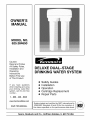
OWNER'S
MANUAL
MODEL NO.
625.384650
Caution:
Read and Follow
All Safety Rules,
Installation and
Operating
Instructions
Before First Use
of This Product.
If you have questions
when installing and using
your drinking water filter
system, call this toll-free
number...
DELUXE DUAL-STAGE
DRINKING WATER SYSTEM
• Safety Guides
• Installation
• Operation
• Cartridge Replacement
• Repair Parts
1 - 800 - 426 - 9345
www.KenmoreWater.com
SAVE THIS MANUAL
System tested and certified by NSF International to
ANSl/NSF Standard 42 and 53 for the reduction of
the claims specified on the performance data sheet.
Sears, Roebuck and Co., Hoffman
Estates, IL 60179 USA
SAFETY GUIDES / SPECIFICATIONS
• Read all steps and guides carefully before installing and using your undersink
drinking
water filter
system. Follow all steps exactly to correctly
install.
Reading
this manual
will also help you to get all the
benefits
from the undersink
drinking
water filter
system.
•
Use the filter on a potable,
safe-todrink
home
COLD water supply
only. The filter cartridge
will
not purify water, or make it safe to drink. DO NOT
use on HOT water (100°F, max.).
Do not use with
water
that is microbiologically
unsafe
or of unknown
quality
without
adequate
disinfection
before or after the system.
This system is certified
for
cyst reduction
and may be used on disinfected
waters that may contain
filterable
cysts.
•
Check with your local public works department
for plumbing
and sanitation
codes. You must fol-
low their guides
as you install the system. Follow
your local codes if they differ with guides in this
manual.
In Massachusetts,
plumbing
codes of
Massachusetts
shall be adhered
to. Consult with
your licensed
plumber.
•
The undersink
drinking
water filter system
works on water pressures
of 30 psi (minimum)
to 100
psi (maximum).
If your house water pressure
is over
the maximum,
install a pressure
reducing
valve in
the water supply pipe to the filter system.
•
Read the other limits (pH, hardness,
etc.) in the
specifications
and be sure your water supply
conforms.
•
Protect the undersink
drinking
water filter system and piping from freezing.
Water freezing in the
housing
will break it.
Min. - Max. Supply Water Pressure
30 - 100 psi
Min. - Max. Supply Water Temperature
40 - 100 "F
Inlet - Outlet
3/8" fittings and
tubing included
Rated Service Flow
0.6 gpm at 60 psi
\
WARRANTY
FULL ONE YEAR WARRANTY
ON UNDERSINK
DRINKING WATER FILTER SYSTEM
For one year from the date of purchase, Sears will replace this Undersink Drinking Water Filter System (except
filter cartridges, which are purchased separately), free of charge, if defective in material or workmanship.
WARRANTY IS AVAILABLE BY SIMPLY RETURNING THE UNDERSlNK DRINKING
SYSTEM TO THE NEAREST SEARS STORE THROUGHOUT THE UNITED STATES.
WATER FILTER
This warranty gives you specific legal rights, and you may have other rights which vary from state to state.
Sears, Roebuck and Co., DEPT. 817 WA, Hoffman Estates, IL 60179
TABLE
Parts of the System
Materials
Needed
Drinking
Water
Installing
Making
Using
Supply
Cartridge
Repair
Parts
Installation
Fitting
Faucet
Tubing
the Filtered
Filter
/ Typical Installation
Drawing
................................................
Filter System
Installing
OF CONTENTS
/ Tools and
4
...........................
.....................................
5
............................................
Connections
Water
5 - 7
System
Life / Replacement
5 - 6
..................................
7
...................................
8
.................................
8 - 9
...................................................
Locate the water filter housing on the cold water supply
cold drinking
water. Refer to the following
drawing.
10 - 11
pipe,
under
the kitchen
or bathroom
sink, to filter the
FILTERING WATER TO ONE FAUCET
filtered water faucet
kitchen sink
DRINKING WATER
FILTER SYSTEM
COLD
FILTER I
FILTER II
PARTS
filter system
et and screws
water
supply
filtered
water
OF THE SYSTEM
assembly
including
MATERIALS
mounting
brack-
fitting
faucet
for sink or countertop
AND TOOLS
•
plumbers
•
Phillips
•
pliers
•
tubing
•
pipe joint compound
NEEDED
putty
screwdrivers
and adjustable
jaw wrench
cutter
or Teflon
tape
mount•
electric drill and 1" drill bit if mounting
needed
for the faucet, see page 6
ing
3/8"
tubing
to make
all needed
connections
hole is
CAUTION:
To avoid damaging
the sink, consult
qualified plumber
or installer for drilling procedures
in porcelain
or stainless steel.
TYPICAL UNDERSINK
a
INSTALLATION
FIG. 1
filtered water
faucet
\
\
- - _
supply fitting
HOT/_
COLD
shutoff valve
Note: To change the filter cartridge, you must
turn offthe water and release pressure by opening the faucet. A nearby
shutoff valve is convenient. Most sinks already
have
shutoff
valves on the supply
pipes.
\
\
15-1/2"
rain.
WATER
OUT
up from
floor
Monitor
Cable
WATER
"_
J
IN
/
tubing
Filter I
Filter II
Note: Be sure to allow a minimum space of 1 - 1/2" under
the system for removing the sumps, to change the
cartridges.
INSTALLATION
STEP 1 - COLD WATER
STEPS
SUPPLY FITTING
Check and comply with local plumbing
codes as you plan, then install a cold feed (supply) water fitting. The
fitting must provide a leak- tight connection
to the water filter 3 / 8" tubing. A typical connection
using the included water supply fitting is shown in FIG.2 - A. An optional
connection
using standard
plumbing
fittings
(not included),
is shown in B.
A.
WATER
1. Close
SUPPLY
the
house
FITTING
main
water
open faucets to drain water
pipe.
2. Remove nut that connects
cold water
B. OPTIONAL
shutoff
valve
and
from the sink cold water
the cold water
faucet
to
plumbing.
3. Use pipe joint compound or Teflon tape on cold water
faucet stud threads and on the male threads of the water
supply
fitting
that connect
4. Thread water supply
nut to bottom of fitting.
to the cold water
pipe.
PIPE FITTINGS
(compression
type
shown)
Note: Be sure to turn off the water
a low faucet to drain the pipe.
supply
and open
Complying
with plumbing
codes, install a fitting on
the cold water pipe to adapt 3 / 8" OD tubing. A typical connection
is shown in figure 2B. If threaded
fittings are used, be sure to use pipe joint compound
or
Teflon tape on outside threads.
fitting onto pipe and reconnect
FIG. 2
A,
B.
WATER SUPPLY CONNECTION
(using included water supply fitting)
WATER SUPPLY TYPICAL CONNECTION
(using compression
fitting)
- parts not included faucet stud
cold water t
water supply fitting
3/8" tubing to
Water Filter inlet
/
co,d
_ia;eer
I
I
:
3/8" compression
fitting
insert
ferrule
f
J
cold
water
pipe
cold water
shutoff
3/8" tubing to
Water Filter inlet
INSTALLATION
STEP 2 - MAKE
HOLE
WATER
FOR FILTERED
in porcelain
or stainless
made for this.
FAUCET
Select one of the following places
Be sure there's room underneath
the needed connections.
STEPS
to install the faucet.
so you can make
steel.
Special
2. Place plumbers
putty around
the drilled
prevent water leaks around the faucet.
-- In an existing sink spray attachment
hole.
-- Drill a hole in the sink top.
- - Drill a hole in the countertop
next to the sink.
FIG. 3
....
....
make
a 1" to 1-1/4"
INSTALL
1. Faucet,
1. Remove
2. Slide
through
hole
diameter
CAUTION:
To avoid damaging
the sink, consult
qualified
plumber
or installer for drilling procedures
STEP 3 - ASSEMBLE
bits are
1" to 1- 1/4"
diameter hole
through sink or
countertop
,
1. If drilling is needed
hole for the faucet.
drill
a
p,umber
putty
FIG. 4
AND
FAUCET
FIG. 4:
the large
nut from the faucet
the faucet stud and
the sink or countertop
telephone
hole.
faucet & spout
threads.
style
wire
ASSEMBLED IN
MOUNTING HOLE
3. On the underside
of the sink or countertop,
screw
the nut on the faucet threads
with the wire running
through
the slot in the washer.
Tighten
the nut so
the faucet cannot move, but do not overtighten.
....
4. Connect
tubing to push to connect fitting on bottom of faucet stud per instructions
on page 7.
5. Connect the telephone
style wire to the recepticle
on PWA board in the manifold
and route the wiring
through
slots in top cover and manifold
assembly.
gasket
/
plumbers
hole in sink or
countertop
slotted
washer
_'_-----
TUBING FROM DRINKING
WATER SYSTEM
<_:71/
\
nut
to
INSTALLATION
STEP 4 - MAKE
TUBING
CONNECTIONS
1. Allowing
some slack, measure
and cut a length of
3/8" tubing to connect between
the supply
fitting
and the filter system inlet, FIG. 1. Cut the ends of the
tubing square.
STEPS
To Disconnect
Tubing, FIG. 5 - B: Push the collet inward and hold with a finger while pulling the tubing
out.
FIG. 5 - A
Tubing correctly cut and connected
2. Insert tubing all the way into the supply fitting and
inlet fitting.
Pull on the tubing
to be sure that it's
held firmly in the fitting.
cut tubing s_uare
3. Repeat steps I and 2 to connect tubing between the
filter system outlet and the adaptor
on the bottom of
the faucet stud, FIG. 1.
TUBING
(all push-
t
I
locations)
1. Use a sharp
square.
engagement
3/4" (3/8" tubing)
-4_
l
FIG. 5 - B
cotlet (depress to
remove tubing)
FIG. 5 - A:
cutter
I
_E-
This system includes
push- in fittings for quick tubing connection
at most locations.
If working with the
fittings do the following.
Connection,
I
end of tubing round and
smooth,
with no cuts,
nicks or flat spots
CONNECTION
in fitting
:
or knife to cut the end of tubing
2. Inspect the end (about 1") of the tubing to be sure
there are no nicks, scratches
or other rough spots. If
needed
cut the tubing again.
3. Push tubing through
the collet and all the way into
fitting. Full engagement
is 11/16" for 1/4" tubing,
and 3/4" for 3/8" tubing.
If tubing
other than supplied
with the system
is
used, be sure it is of high quality,
exact size and
roundness
with a smooth surface.
r
I
I
I
I
9 and
follow
all steps
CAUTION
under
I
DO NOT USE VINEGAR,
OR OTHER ACID
BASED CLEANERS ON THIS SYSTEM. THEY
WILL DEGRADE SOME SYSTEM PARTS. ALWAYS USE SOAP AND WATER.
I- ....................
STEP 5 - FILTER CARTRIDGE
Turn to page
1
I
I
I
I
I
J
INSTALLATION
"Filter
Cartridge
Replacement".
A taste and odor cartridge
contains activated
carbon, a black powder.
After the new cartridge
the filtered water faucet and allow fine, harmless
carbon particles
to purge from the cartridge.
when you no longer see the "fines" in the filtered water, or approximately
2- 3 minutes.
is installed,
open
Close the faucet
USING THE SYSTEM
The sink or countertop
faucet has a hand operated
knob to access drinking water.
Turning the knob to
the left opens the faucet, turning to the fight shuts off
the faucet.
FAUCET
Z
ELECTRONICS
only"AA"
alkalinebatteries.
Improper
placement
of
batteries
could damage
electronics.
Use care when
inserting
batteries
to align them correctly
in manifold with the proper polarity.
The Undersink
Drinking
Water Filter will monitor
the total water flow of the unit and also length of time
the filters have been installed.
The faucet base has an
indicator
light that flashes
of the filters.
to inform
faucet
filtered water
you of the status
Green - Filters are good. Amber - Warning,
filters
need repladng
shortly.
Filters need replacing,
when
water has been drawn, after 168 days (or 960 gallons
have been used) since battery change.
Red - Filters
must be replaced.
Will flash after 14 additional
days
(or 80 additional
gallons).
If the faucet LED indicator light does not function after a battery change, and the batteries
are known to
be good and installed properly,
there may be a residual charge on the static protection
device.
To dissipate this charge, remove the batteries
for one hour.
When the two "AA" batteries
are first applied at initial start up, the LED indicator light will flash in a amber, green, red sequence.
All timers and counters
are
reset to zero.
In order to reset the monitor
time and gallon count
feature, the batteries
should be removed
for a minimum of five seconds
and then reinserted.
Batteries need to be replaced
once a year at the time
of filter replacement.
Do not mix battery types, use
FILTER CARTRIDGE
FILTER
CARTRIDGE
Several variables
determine
will last. These include:
1. how much
water
how
/ USEFUL
LIFE
long
Kenmore
system
model
ment elements
42-38466
a cartridge
625.384650
with replacehas been tested and certi-
fied by NSF International
for the reduction
of chlorine, lead, asbestos,
cysts, VOC's and MTBE.
The
rated capacity for this system is 1040 gallons.
you use
2. how much sediment,
taste and/or
unwanted
substance,
is in the water
LIFE / REPLACEMENT
odor,
or other
Use the following
information
as a guide. However,
no matter which type of cartridge
you are using, you
will know it is time to replace it when you first notice the return
of the unwanted
substance
in your
water.
8
FILTER CARTRIDGE
CAUTION:
Never remove
sure in the filter system.
sumps
with
water
pres-
1. Close the water supply
page 4) to the filter. Open
shut-off
valve (FIG. 1,
the filtered water faucet
REPLACEMENT
to relieve
pressure
in the system.
2. Turn the sump off of the filter head, to the left or
clockwise
1/4 turn. Be careful, the sump is full of water. Do not lose the large o-ring seal.
FIG. 6
ca_ridge
head
o-ring
seal
S
TURN
SUMP
COUNTERCLOCKWISE
TO TIGHTEN
TURN
SUMP
CLOCKWISE
TO REMOVE
Filter I
Filter II
3. Be sure the inside of the sump
soapy water and rinse thoroughly.
is clean.
Use hot,
9. Open the filtered water faucet. Then, slowly open
the water supply valve and allow the filter housing
to fill.
4. Remove the wrapper
from the new filter cartridge
and insert the filter cartridge
in the sump. Be sure the
two o-rings
are towards
the filter head.
10. Close the filtered
tween
Note: If you are installing two different types of filter
cartridges,
be sure to install in filters I and II as the
guideline
on page 3 shows.
11. Remove
timer.
6. Hold the sump up to the filter head aligning
the
protrusion
on the cartridge
with the center hole in the
bottom of the head.
8. Repeat
steps
2 through
onto
Check
for leaks be-
and the head.
and replace
batteries
to reset counter
and
12. Taste and Odor Cartridges:
A taste and odor cartridge contains
activated
carbon,
a black powder.
When new, open the filtered water faucet and allow
fine, harmless
carbon particles to purge from the cartridge. Close the faucet when you no longer see the
"fines"
in the filtered water, or approximately
2-3
minutes.
Note: If the sump will not tighten up to the head you
may have the cartridge in upside down. Take the cartridge out and check for correct orientation.
the sump
faucet.
Note: If leaking, turn off the water supply and open
the filtered water faucet to depressurize
the filter.
Then disassemble
the filter and check the o-ring for
cuts, flat spots, etc., and sealing surfaces for foreign
material. Clean the o-ring and lubricate
with silicone
grease or Vaseline. Carefully press the o- ring into the
groove in the sump.
5. Lightly lubricate
the o- ring seal in the sump with
silicone grease or Vaseline. Be sure it is fully seated
in its groove.
7. Turn (counterclockwise)
head 1/4 turn.
the sump
water
the filter
7 at the other filter.
9
REPAIR
Kenmore
Deluxe Dual-Stage
PARTS
Drinking Water System, Model No. 625.384650
7
I
_6
5
2
1
lO
REPAIR
PARTS
LIST
KEY
NO.
PART
NUMBER
1
7221128
2
3
7223633
42-38466
4
9006062
Screw (2 req.)
5
9041700
Hanger Washer (2 req.)
6
7234210
Paddlewheel & O-Ring Kit
7
7234228
Paddlewheet Cover & Screw Kit
8
7234252
Rep'l Pwa (includes screw)
9
7234286
Cover, Manifold
10
7226495
Faucet
11
7228536
Feed Supply Fitting
_1,
7157280
Tubing, 3/8" x 20' - white
41,
7227467
Owners Manual
DESCRIPTION
Sump (2 req.)
O-Ring (2 req.)
Filter, Carbon Block (2 Pack)
_1, not illustrated
11
UNDERSINK DRINKING
WATER FILTER
SYSTEM
OWNERS
MANUAL
For the repair or replacement
parts you need
Call 7 am - 7 pm, 7 days a week
MODEL NO.
1 - 800 - 366 - PART
625.384650
(1 - 800 - 366 - 7278)
For in-home
major brand repair service
Call 24 hours a day, 7 days a week
The
model
number
1 - 800 - 4 - REPAIR
of
(1 - 800 - 473 - 7247)
your drinking water filter
system is found on the
rating decal, located on
the back of the post filter.
For the location
Sears
When requesting service
or ordering parts, always
provide the following information:
4,
4,
4,
4,
Product Type
Model Number
Part Number
Part Description
www.KenmoreWater.com
Repair
Service
of a
Center
in your area
======
Call 24 hours a day, 7 days a week
1 -800-488-1222
For information
on purchasing
a Sears
Maintenance
Agreement,
or to inquire
about an existing Agreement
Call 9 am - 5 pm, Monday
SEARS
- Saturday
1 - 800 - 827 - 6655
SEARS
I; t: ;'.v/;l.J-t; i _,__l
America's Repair Specialists
Sears, Roebuck and Co., Hoffman Estates, IL 60179 U.S.A.
7227467 (Rev. C 05/11/01)