1
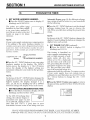
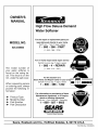
OWNER'S
MANUAL
MODEL NO.
625.348600
Caution:
Read and Follow
All Safety Rules and
Operating Instructions
Before First Use of
This Product.
High Flow Deluxe Demand
Water Softener
• Warranty
If you have questions when
installing, operating or maintaining your softener,
and
when setting the timer, call
this toll-free
number...
1-800-426-9345
• Start Up / Setting Timer
• How It Works
• Care Of
• Specifications
SAVE THIS MANUAL
• Repair Parts
Use plastic bag and tie provided, to hang manuals nearby
the softener for future reference.
Sears, Roebuck and Co., Hoffman Estates,
PRINTED IN U.S.A.
IL 60179 USA
WARRANTY
I
I
SEARS RESIDENTIAL
FULL ONE YEAR WARRANTY
WATER SOFTENER
ON WATER SOFTENER
For one year from the date of purchase, when this water softener is installed and maintained
in accordance with our instructions,
Sears will repair, free of charge, defects in material or workmanship
in this water softener.
FULL TEN YEAR WARRANTY
AGAINST
LEAKS
For ten years from the date of purchase,
Sears will furnish and install a new current
softener tank or salt storage drum, free of charge, if either the tank or drum develop
model water
a leak.
TO O BTAI N WAR RANTY SE RVl CE, S l M PLY CO NTACT TH E N EAREST SEARS SE RVl CE CE NTE R
THROUGHOUT
THE UNITED STATES. This warranty applies only while this product is in use in the
United States.
This warranty
state.
gives you specific
Sears,
legal rights, and you may have other rights which vary from state to
Roebuck
and Co., D/817 WA, Hoffman
If you want your water softener professionally
prompt,
quality installation
by Sears Authorized
SEARS
INSTALLATION
installed,
talk to your
Installers.
POLICY
SEARS
All installation
labor arranged
by Sears shall be
performed
in a neat, workmanlike
manner in accordance with generally
accepted
trade practices.
Further, all installations
shall comply with all local laws,
codes, regulations,
and ordinances.
Customer
shall
also be protected,
during
installation,
by insurance
relating
to Property
Damage,
Workman's
Compensation
and Public Liability.
Estates,
Sears
IL 60179
Salesman.
INSTALLATION
He will arrange
for a
WARRANTY
In addition
to any warranty
extended
to you on the
Sears merchandise
involved,
which warranty
becomes effective the date the merchandise
in installed,
should
the workmanship
of any Sears arranged
installation
prove faulty within one year, Sears will,
upon
notice
from
you, cause
such
faults
to be
corrected
at no additional
cost to you.
FACTS AND FIGURES TO KEEP
Fill in the blanks below and keep this book in a safe
place so you always have these facts.
Water Softener Model No.t
Serial Number
Date Installed
Water Hardness
Grains Per Gallon
Iron Content
Parts Per Million
Taste And/Or Odor
*pH
Water Pressure
Pounds/Square Inch
Water Flow Rate
Gallons Per Minute
i The model number is on the rating decal, located
on the rim, under the salt hole cover.
2
TABLE OF CONTENTS
L
I
PAGE
NO.
SECTION 1
A.
B.
C.
D.
E.
OTHER
THINGS
SERVICE
TROUBLESHOOTING
ROTARY VALVE SERVICE
WATER FLOW THROUGH
SECTION 6
4
5
6-7
8
9
WORKS
10-11
12-14
CARE OF YOUR SOFTENER
15
16
17
18
TO KNOW
19
DIMENSIONS/SPECIFICATIONS
SECTION 5
A.
B.
C.
HOW YOUR WATER SOFTENER
SALT: REFILLING STORAGE TANK, SALT BRIDGE
KEEPING THE WATER SOFTENER CLEAN
KEEP THE SOFTENER FROM FREEZING
HELPFUL HINTS CHECKLIST
SECTION 4
A.
TO INSTALL
FACE PLATE TIMER FEATURES
SOFT WATER SERVICE AND REGENERATION
SECTION 3
A.
B.
C.
D.
START UP
SAFETY GUIDES
CHECK LIST OF STEP-BY-STEP
GUIDES
PROGRAM THE TIMER
SANITIZING THE WATER SOFTENER
FILL THE STORAGE TANK WITH SALT
SECTION 2
A.
B.
SOFTENER
TECH INFORMATION
THE SOFTENER
REPAIR PARTS
3
VALVE
20-23
24
25-27
28-31
SECTION
1
WATER SOFTENER
START-UP
I
1A.
SAFETY GUIDES
• Read all steps, guides and rules carefully before
installing and using your new water softener. Follow
all steps exactly to correctly install. Failure to follow
them could cause personal injury or property damage. Reading this book will also help you to get all of
the benefits from your water softener.
• Your water softener will remove hardness minerals and "clear water" iron from water, up to the limits
shown on page 19. It will not remove other types of
iron, acids, tastes and odors, etc. It will not purify
polluted water or make it safe to drink.
• Protect the softener and piping from freezing.
Damage from freezing voids the softener warranty.
See page 17.
CAUTIONS
PLEASE READ AND COMPLY WITH
ING GUIDES TO PREVENT
DAMAGE
ENER OR OTHER PROPERTY,
OR POSSIBLE
FATAL SHOCK.
• THIS SOFTENER
WORKS
THE FOLLOWTO THE SOFT-
PERSONAL
ON 24 VOLTS
SURE TO USE THE TRANSFORMER
AND PLUG IT INTO A 120V OUTLET.
INJURY,
ONLY. BE
INCLUDED,
• Unplug the transformer right away if the power
cable sould become damaged or frayed. Make repairs before plugging back into the power outlet.
• Always unplug the softener from electrical power
before removing outer valve covers.
4
SECTION
1
WATER
SOFTENER
START-UP
I
I
1 B.
CHECK
To be sure you have
softener,
read
the
Installation
Manual,
step guides.
Page numbers
Manual
unless
LIST OF ALL STEP-BY-STEP
GUIDES TO INSTALL
done all the steps to install the
following
list. Refer
to the
part no. 7183613, for step-by-
referred
to are in the
otherwise
noted.
?y
-
Installation
DZg
i
Is the house water flow going INTO the softener
valve INLET? Trace piping to be sure. See pages
10 and 11.
Is the plumbingbypass
valve (or 3 valves) set for
SERVICE?
Bypass
valve(s)
should
always
remain in soft water service
position.
Position
in
"bypass"
only if needed
for softener
repairs. See
FIG. 12, page 19 of this manual.
Is the valve drain hose connected
the right way,
and without
sharp
bends
or kinks that could
stop or reduce water flow? See page 16.
3-valve
Page numbers
Manual
unless
referred
to are in the
otherwise
noted.
Installation
plastic
Is the softener
power
cable connected
to the
transformer?
Is the transformer
plugged
into an
inside,
120V-60Hz
electrical
outlet?
See page 20
in the installation
manual,
and the wiring
schematic on page 20 of this manual.
Be sure
to restart
the water
NOTE: The state of Massachusetts
plumber to perform the installation.
heater.
See page
requires
_ ___, !
_'_
_
Bypass Valve(s)
20.
a licensed
5
SECTION
1
WATER SOFTENER
START-UP
I
1C.
signal light adjust
PROGRAM
salt level adjust
THE TIMER
UP button
display
SELECT button
\
f
High Flow
Deluxe Demand Water Softener
Kenmore Water Line
for Customer Assistance
1-800-426-9345
LOW
SALT
RECHARGE
RECHARGE
_
with Dual Segment
NOW
TONIGHT
Electronic
Display
/
ON/OFF-HOLD button
(Recharge Tonight-Now)
DOWN button
When
the transformer
is plugged
in, the model
code HF31, and a test number
(example:
k11) show
in the face plate display
for 4 seconds.
Then, 12:00
AM and PRESENT
TIME begin to flash.
button.
For example,
while setting
the hardness
(step 2), the beeper
sounds
repeatedly
when the
display
reaches
I using the DOWN
button,
or the
highest
hardness
setting using the UP button.
1. SET PRESENT
I -I,NN _=
IC'LILI
,, II
I/
PRESENT
TIME OF DAY:
NOTE:
TIME
If the
words
PRESENT
TIME
display,
press
the SELECT
they do, or see the previous
NOTES:
If SR - - shows in the display,
DOWN
[_button
until HF31
button
notes.
(FIG.
in the
1) until
• Press the UP / DOWN buttons
to set the present
time. Press UP to move the display
ahead;
press
DOWN
to move the time backward.
press the UP [] or
shows. Then, press
the SELECT button to set, and change
ing PRESENT
TIME display.
do not show
to the flash-
If the present
time
noon and midnight,
is between
be sure PM
If the present
midnight
and
shows.
SOUND
"BEEPER":
A "beeper"
sounds
while
pressing
buttons
for timer set-up. One beep signals
a change
in the face plate display.
Repeated
beeps
mean the timer will not accept a change
from the
button you have pressed,
telling you to use another
time
noon,
is between
be sure AM
r'[ PM
q,_-II_-I
PRESENT
shows.
To check the model
code, unplug
the transformer
at the wall outlet and plug in again, if other than
HF31 shows,
see page 18 to reset.
I I,C
TIME
I h-I_ _M
i i,_70
PRESENT
TIME
NOTE:
Each press of the UP/DOWN
buttons
time by i minute.
Holding
the buttons
the time 32 minutes
each second.
6
changes
the
in changes
SECTION
1
WATER
1 C.
2.
PROGRAM
SET WATER HARDNESS
• Press the SELECT button
(flashing) and HARDNESS.
NUMBER:
once to display
Automatic
Bypass,
time setting
would
do the following.
25
recharge
AM-PM
of day.
HARDNESS
4.
20 gpg hardness
+10
30 HARDNESS
NUMBER
generation
At the 2:00 AM recharge
setting,
the softener
begins
generation
(see pages
12
13) at 2:00 AM, ending
no
than
4:00 AM. This is
households
because
water
IF YOU NEED
1-800-426-9345.
the
time
to display
TIME.
the
the
OFF
nrr
ur rCLEAN
n I
UrCLEAN
sequence (see page
12). This provides
extra cleaning of the resin bed before it is
regenerated
with the salt brine. To conserve
water,
if your
water
supply
does
not contain
iron or
sediments,
be sure this feature is set to OFF. Use the
UP / Down
buttons
to change
the ON / OFF
displays.
button
changes
the
Between
25 and the
changes
5 at a
the UP or DOWN
twice each second.
(REGENERATION)
• Press the SELECT button
(flashing)
and RECHARGE
to set the desired
SET CLEAN
FEATURE
(optional):
• Press the SELECT
button
to display
(flashing)
and CLEAN.
When
set to ON, a backwash
and fast rinse cycle will occur
first, preceeding
the normal
re-
NOTE:
SET RECHARGE
buttons
starting
hour.
Be sure to observe
as you did when setting the present
This feature
is beneficial
on
water supplies
containing
iron
and/or
high amounts
of sediments
(sand,
silt, dirt,
etc.).
• Press the UP / DOWN buttons
to set your water
hardness
number
in the display.
The DOWN
button
moves
the display
to 1. The UP button
moves
the display
to the highest
setting
(see
maximum
setting for your model in the specifications).
3.
the UP / DOWN
Each press of the UP / DOWN buttons
changes
display
i hour. Holding
the buttons
in changes
display
twice each second.
If your water supply
contains
iron, compensate
for
it by adding
to the water
hardness
number.
For
example, ass ume your water is 20 gpg hard and con tains
2 ppm iron. Add 5 to the hardness
number for each 1
ppm of iron. In this example, you would use 30for your
hardness n umber.
Each press of the UP / DOWN
display by I between
I and 25.
highest
number,
the display
time...25,
30, 35, etc. Holding
button
in changes
the display
page 14). If a different
recharge
be better
for your household,
NOTE:
NOTE:
2ppmironx5=10
(times)
START-UP
THE TIMER
• Press
The grains
per
gallon
(gpg)
hardness
of your water supply
is on your water
analysis
report. Be sure to enter water test
results
on page
2, for future
reference.
SOFTENER
• Press the SELECT button
once again, to return
the present time, and RECHARGE
TONIGHT
in the
display.
TIME:
2:00 AM
5
3
2
4
1
RECHARGE
TO_iGR?
WAI_HPLOW
time
q,nnA_
I_-'UU
reRECHAROE
TIME
and
later
a good
time
in most
is not being used (see
HELP PROGRAMMING
THE TIMER, CALL TOLL FREE, NUMBER
SEE PAGES 10 AND 11 FOR OTHER FACE PLATE TIMER FEATURES.
7
SECTION
1
WATER SOFTENER
START-UP
I
1D.
SANITIZING
THE WATER SOFTENER
ADD WATER
Care is taken
at the factory
to keep your water
softener
clean and sanitary.
Materials
used to make
the softener
will not infect or contaminate
your
water supply, and will not cause bacteria
to form or
grow. However,
during
shipping,
storage,
installing and operating,
bacteria
could
get into the
softener.
For this reason,
sanitizing
as follows
is
suggested
_ when installing.
salt hole
cover
hose
1.
The first time you sanitize
your softener,
be
sure to do all steps in the installation
manual,
and on pages 5, 6 and 7 of this manual
first.
2.
Lift the salt hole cover and use a pail or hose
fill the salt storage tank with at least 3 gallons
water.
°
,
to
of
brinewelI
water,
Remove
the brinewell
cover (FIG. 3) and pour
about
3/4 ounce,
or 1 to 2 tablespoons,
of
common
5.25% household
bleach (Clorox, Linco, BoPeep,
White
Sail, Eagle,
etc.) in the
softener
brinewell.
Press the ON/OFF-HOLD
seconds to start a recharge.
does several
things.
--
It draws
softener
--
It fills the
ed.
--
It gets
--
It prepares
service.
button
This
the bleach
into
to sanitize
it.
salt tank
to the water
all the air out of the resin
the
resin
bed
about 3 gallon_.,.
and hold for 3
first recharge
and
through
level
the
need-
tank.
(see page
12) for
NOTES:
This recharge
takes about 2-1/2
or 2-3/4
hours,
depending
on the salt type setting
(page 7).
You
salt
can
in the
sanitize
storage
the
softener
with
brinewelI
cover
(remove and add
about3/4 oz. bIeach)
or without
tank.
Recommended
by the Water Quality Association. On
some water supplies, the water softener may need periodic disinfecting.
8
SECTION
1
1 E.
WATER
FILL THE STORAGE
the
softener
dirt and
working.
tank
with
NUGGET
or
PELLET
salt. DO NOT use rock salts, as they
sediments
that will stop the softener
START-UP
TANK WITH SALT
ADD SALT
Brine (salt dissolved
in water)
is needed
for each
and every
regeneration.
The water
for making
brine is metered
into the salt storage
tank by the
softener.
However,
you must keep the tank filled
with salt.
Fill
SOFTENER
water
have
from
\
Before filling, be sure the brinewell
cover is in place
on the top of the brinewell.
Salt storage
capacity
is
shown
on page 20. Be sure to set the salt monitor
system
(see page 10).
brinewelI
cover
NOTES:
salt
The salt monitor
system,
page 10, is calibrated
to
the density
of nugget
or pellet water softener
salt.
The monitor
will not work as accurately
with other
types of salt including
rock and solar.
storage
tank
In humid
areas, it is best to fill the storage
tank
half-full,
and to refill it more often. Salt bridging
(see page 15) occurs
more often when
conditions
are humid.
WATER SOFTENING SALT WITH IRON REMOVING ADDITIVES -- Some salts have an additive to
help the softener handle iron in the water supply.
Although
this additive
may help to keep the
softener resin clean, it may also release corrosive
fumes that will weaken and shorten the life of some
softener parts.
J
brinewelI
Sodium
chloride
Persons
information:
Water softeners
using sodium
for regeneration
add sodium to the water.
who are on sodium restricted
diets should
consider
sodium
the added
intake.
sodium
as part
of their
overall
For example,
if your water supply is 15 grains hard,
you would have to drink 3 quarts of softened
water
to consume
335 milligrams
of sodium.
That is
equivalent
to eating 2-1/2 slices of white bread.
Persons
who are concerned
about
their drinking
water should
consider
a Kenmore
Drinking
Water
System that will remove or reduce in excess of 90%
of the sodium
and other drinking
water contaminants.
You have now finished the water softener start up. After the sanitizing
page 8, the softener will be giving you soft water.
9
recharge,
on
SECTION 2
HOW YOUR WATER SOFTENER
WORKS
I
2A.
FACEPLATE
EXTRA RECHARGE
Sometimes,
a manually
charge) may be desired,
are:
TIMER FEATURES
indicator
light
tank with salt.
started regeneration
(reor needed. Two examples
1. Lift the salt hole cover
storage
You have used more water
than usual
(guests
visiting)
and you may run out of soft water before
the next timer started
regeneration.
- You did not refill
the softener
with
salt before
to remind
you to refill the
To set this monitor
system:
o
it
was gone.
You can start a regeneration
right away, or you can
set the timer to regenerate
at the next 2:00 AM (or
other preset recharge
time). Do the following.
and
level
storage
the salt in the
tank.
The salt level decal,
on the brinewell
inside
the
tank, has numbers
from 0 to 8 (see drawing
page 9 and below).
Observe
the number
leveled
salt is at or closest to.
on
the
o
Now, press the SALT LEVEL ADJUST
button
until black bars display
up to the salt level
number.
For example,
the pictures
below show
the salt level at 6.
o
Finally,
set the level you want
the low salt
indicator
light to come on. Press the SIGNAL
LIGHT
ADJUST
button
until
a (÷) shows
opposite
this number.
In the example
below,
the light will come one when
the stored
salt
drops to level 2. At level 2, the storage
tank is
about
1/3 full. This is the lowest
you should
allow the stored salt level to drop to. To turn the
salt monitor
off, press
the SIGNAL
LIGHT
ADJUST button
until OFF shows above.
RECHARGENOW
button
and
hold
until
*RE-
7
.... REI'c,_--d_
• Press theServ
CHARGE,
ON/andOFF-HOLD
Fill begin
[ ii°_l_
-w,rlr'wPM
to flash in the display.
Upon
.........
reaching
fill, the first cycle of
regeneration,
the flashing
Serv goes off and Fill is
on steady.
RECHARGE
continues
to flash. This
regeneration
will last for about 2 hours. After the
2 hours, you will have soft water again.
*NOTE:
NOTE:
If the CLEAN
feature
backwash
(CLEAN and
is set to ON, a cleaning
Bkwsh or Rinse flashes
in
the display,
along with the minutes
of the
cycle remaining)
precedes
the recharge.
For accurate
salt monitor
operation,
nugget
or pellet water softener
salt.
clean
RECHARGETONIGHT
•
Press
and
release
(do
not
:o_1
i
q,,-nnP.
bars,
levelsalt
brinewelI
button.
RECHARGE
TOhold) the ON / OFF-HOLD
ii ] REC._'_ON,,
NIGHT
flashes in the display,
.........
and the softener
begins regeneration
at the next preset
recharge
time. Press
and release
the ON/OFF-HOLD
button
once
more if you decide
to cancel
and RECHARGE
TONIGHT.
the
salt
level
LOW
SAL_
indicator light
regeneration,
SALT MONITOR SYSTEM
The face plate timer has a low salt monitor
with an
10
always
See page
use
9.
SECTION
2
HOW YOUR WATER SOFTENER
2A.
FACEPLATE
TIMER FEATURES
OPTIONAL
SETTINGSCLEAN
FEATURE
MINUTES, MAXIMUM DAYS BETWEEN REGENERATIONS, and 12 / 24 HOUR TIME READINGS:
WATER FLOW THROUGH
If soft water
-I
MIN
TIME
I
default minutes
CLEAN
3
TIME
the time.
faucets
pliances
MIN
If no change
2. Press
SELECT
again
RECHARGE
display.
default display
to
is desired,
show
the
using this
backwash
However,
minutes
in
UP button
button
to
RECHARGE
_12
SELECT
or 24 hour
the
12 HOUR
All time
displays
are shown
in standard
clock time (1 to 12 PM; and I to
12 AM) at the 12 hr default
setting.
If military
time
displays are desired,
set to 24 hr by
pressing
the UP button.
4. Press
SELECT
ap-
to return
the present
TIME
I'uO
IOF
I
q,N 13_
WATER
FLOW
no water flow
I'UI]
-I,I-II-IpM
i °F]
#_
WATER
FLOW
/
Flow bars scroll when
soft water is in use.
REMAINING
and
valve
position
indicators
VALVE
recharge
time
remaining
_oF_
continue
*NOTE
on page
10 if the
RET'_g_EgA"'_
softener
is
recharging
(See
i _,i ,UO
I1-11-1
M,-]
i
CLEAN
feature
is ON).
RECHARGE
flashes in the display
and, beginning
with Brine, the minutes
of recharge
remaining
before return to service appears
in place
of the present time. When the valve is moving from
one cycle to another,
both position
indicators
are
flashing.
following
example: set to 4 days maximum between regenerations
to show
clock:
using
POSITION
INDICATORS
One of the valve position
indicators (Serv, Fill, Brine, Bkwsh,
Rinse)
is displayed
while
the
_Maximum
days
between
regenerations:
The
faceplate
timer
automatically
controls
regeneration frequency
(see page 14). This provides
the
greatest
operating
efficiency,
and normally
the
maximum
days feature is not needed.
If you want to
be certain
a regeneration
will occur
within
a
number
of days, use this feature.
For example,
if
your water supply
contains
iron and you want the
softener
to regenerate
at least once every few days
to keep the resin bed clean,
set the display
as
typically
shown
above. Setting is available
from 1
to 15 days by using the UP and DOWN
buttons.
3. Press
and water
are off.
example: time set to 3minutes
_CLEAN
feature
minutes:
If you are
feature
(page 7), the length of the extra
cycle automatically
sets to 7 minutes.
you can adjust this time from 1 to 15
length. To change this cycle time, use the
to increase
the time,
or the DOWN
shorten
below.
THE SOFTENER
is in use, the water
flow
bars
continually
scroll
across
the display.
The bars
scroll slowly when
water flow
is slow,
and move
faster
as
water flow increases.
The flow
bars
do not show
when
all
1. To set 1, 2 or all 3 options, press and hold SELECT
for 3 seconds. Then press again until the CLEAN
TIME display shows.
CLEAN
WORKS
PROGRAM
MEMORY
If electrical
power to the softener
goes off, the time
display
is blank but the face plate timer keeps the
correct
time for about
12 hours.
When
electrical
power
comes
on again,
you have
to reset the
present
time only if the display
is flashing.
The
HARDNESS
and RECHARGE
TIME never require
resetting
unless a change
is desired.
Even
outage,
your
occur
timer
display.
II _WhF _;
if the timer is incorrect
after a long power
the softener
works
as it should
to keep
water
soft. However,
regenerations
may
at the wrong time of day until you reset the
to the correct time of day.
ERROR
CODE
TIME
An error code could appear
in
the face plate display
if a problem occurs in the softener
elec-
2clhc
_-F F I
tronics. If you see an error code
instead
of the present
time of day, please call your
local Sears Service Department
for service.
TIME
time display.
11
SECTION 2
HOW YOUR WATER SOFTENER
WORKS
I
2B.
SOFT WATER SERVICE AND REGENERATION
SERVICE
REGENERATION
When the softener
is giving
you soft water, it is
called "Service".
During
service, hard water comes
from the house main water pipe into the softener.
Inside the softener
resin tank is a bed made up of
thousands
of tiny, plastic resin beads
(FIG. 4). As
hard water
passes
through
the bed, each bead
attracts
and holds the hardness
minerals.
This is
[]
Brine
FILL: Salt, dissolved
is needed
to clean
from the resin beads.
To make
the brine,
water
flows into the salt storage
area during
the fill stage
as shown
in FIG. 5. Fill cycle length
depends
on
how much soft water making
capacity
you have
used since the last regeneration.
As you use more
water, fill time increases
so more brine is made. The
called ion-exchanging.
It is much like a magnet
attracting
and holding
metals.
Water without
the
hardness
minerals
(soft water)
flows out of the
softener
and into the house soft water pipes.
greater
minerals
amount
of brine
cleans
from the resin bed.
After a period of time, the resin beads hold all of the
hardness
minerals
they can, and cleaning
with salt
brine is needed.
This cleaning
is called regeneration or recharge.
Regeneration
is started
at 2:00
a.m. by the electronic
timer (see page 14). It takes
place in 5 stages or cycles. These are:
FT]
[]
F]
FILL
BRINING
BRINE RINSE
in water, is called brine.
the hardness
minerals
WATER FLOW THROUGH
SOFTENER IN FILL
soft water
OUT
r-_ BACKWASH
r_ FAST RINSE
q
NOTE:
salt storage
tank -...
If the Clean feature
is set to ON,
additional
backwash
and fast rinse cycles occur before the fill
cycle.
WATER FLOW THROUGH
SOFTENER IN SERVICE
soft water
OUT
-j
brine valve
THE
\\\\\\
hard water
IN
,
\
fill water
salt storage
tank (salt .
not shown)
_'
brine valve
more
resin tank
resin bed
12
hard water
IN
hardness
THE
SECTION
2
2B.
[-2]BRINING:
During
from the salt storage
the resin tank, brine
HOW YOUR WATER SOFTENER
SOFT WATER SERVICE
brining,
the brine
depends
hard water,
out the
the resin
bypass OUTt
on:
- -the
amount
--how
fast
The
take
resin
slow
least
AND REGENERATION
WATER FLOW THROUGH THE
SOFTENER IN BACKWASH
is moved
area, into the resin tank. Inside
cleans hardness
minerals
from
the resin beads
and they are discharged
drain. How much brine is needed
to clean
WORKS
hard water
! IN
drain
of resin
the brine
in the softener,
goes
through
the bed.
nozzle
and venturi
(FIG. 6) make
suction
to
brine from the salt tank and put it into the
tank. They keep the brine flow down to a very
rate to get the best resin cleaning
with the
salt.
[3]BRINE
RINSE: After
into the resin tank, the
resin bed lifted
and expanded
all of the brine is moved
brine
valve closes. Water
keeps flowing
the same way it did during
brining
except
the brine
flow
has stopped.
Hardness
minerals
and brine flush from the resin tank to the
[-_FAST RINSE: Backwash
flow of water down through
flow packs the resin bed and
to service (FIG. 8).
drain. Brining and brine rinse together
vary in the
length
of time they take, relative
to the fill cycle
length.
WATER FLOW THROUGH THE
SOFTENER IN BRINING AND
BRINE RINSE
hard water
bypass OUTt
is followed
by a fast
the resin tank. The fast
gets it ready for return
After fast rinse, the softener
returns
to service.
Hard water goes into the resin tank where the resin
bed again takes
out the hardness
minerals.
Soft
water goes to the house soft water pipes.
hard water
I
WATER FLOW THROUGH THE
SOFTENER IN FAST RINSE
IN
drain
soft water
hard water
OOT ! '"
drain
brine
[4]BACKWASH:
During
backwash,
water
flows
UP through
the resin tank (FIG. 7) at a fast rate to
flush iron minerals,
dirt and sediments
from the
bed and to the drain.
good cleaning.
The bed
lifts and expands
for
13
SECTION 2
HOW YOUR WATER SOFTENER
WORKS
.I
2B.
SOFT WATER SERVICE
AUTOMATIC
BYPASS
ELECTRONICS
During
the brining,
brine
rinse
and backwash
cycles of regeneration,
HARD water goes through
the softener valve and to the house pipes. If a faucet
is opened,
hard water
is there for your needs.
However,
you should not use hot water, if possible,
because
the water
heater
will refill with
hard
water. The softener, as factory
erates from 2:00 AM to about
not much water is used.
AND REGENERATION
Two main parts of the softener's
electronics
WATER METER, and [] a COMPUTER.
are [] a
[] WATER METER -- The water meter
is in the
softener
valve outlet. As water flows through
the
meter, it sends electric pulses to the computer.
The
computer
changes
the pulses
to a measure
in
gallons
of water.
programmed,
regen4:00 AM, a time when
[] COMPUTER
-- The computer
is part of the
faceplate
timer circuit board. It is programmed
to
know the softener's
capacity
(how many grains of
hardness
minerals
it will take out of the water
If you get up early in the morning
and you can hear
the softener
regenerating,
change
the recharge
starting
time. Set the recharge
time to 12:00 AM or
1:00 AM (page 7). Then regeneration
will start and
end that much earlier and your water heater will
not refill with hard water if a hot faucet is opened.
before a regeneration
is needed).
When starting
the
softener,
page 7, you set it for the grains per gallon
(gpg) hardness
of the water.
To find a regeneration
pattern
best for your needs,
the computer
uses: (1) water usage from the meter,
(2) hardness
setting,
(3) softener
capacity,
and (4)
time since the last regeneration.
The computer
always
adjusts
this pattern
to your water
using
habits.
It works
toward
providing
you with soft
water for the longest time and at the most efficient
salt usage.
Softening
capacity
is used
as hard
water
goes
through
the softener
and hardness
minerals
are
removed.
When
the computer
determines
that
only enough
capacity
remains
to provide
soft
water
up to the next regeneration
starting
time
(2:00 AM, or as otherwise
set) it will schedule
a
regeneration.
RECHARGE
TONIGHT
displays
until the regeneration
begins. When the regeneration
begins,
TONIGHT
goes off and *RECHARGE
or
RECHARGE
TIME REMAINING
flashes
during
the 2 hour regeneration.
* NOTE:
If the CLEAN
feature
is set to ON, a cleaning
backwash
(CLEAN and Bkwsh or Rinse flashes
in
the display,
along with the minutes
of the clean
cycle remaining),
precedes
the recharge.
14
SECTION
3
cAREOF'tOUR
SO .ER
I
I
3A.
WHEN
SALT...REFILLING
TO REFILL
WITH
STORAGE
SALT: The Salt Monitor
have hard water.
tor System, page
System (see page 10) will turn the low salt light on
to warn you when to refill with salt. Check for a
low salt light a few weeks
after you install
the
softener,
and every week after that. Always
refill
at about the #2 salt monitor
level. At this level, the
tank is about 1/3 full. Never let the softener
use all
the salt before
refilling.
Without
TANK/BREAKING
A SALT BRIDGE
After
10.
filling,
reset
the
Salt Moni-
NOTE:
You will have a loss in softening
capacity
and
get partly
hard water
if less than 10 inches
monitor
level 2) of salt is in the storage
tank.
salt, you will soon
may
(salt
PLEASE SEE PAGE 9 FOR SALT FILLING DIRECTIONS.
BE SURE TO RESET THE SALT MONITOR,
PAGE 10.
SALT BRIDGE
SALT BRIDGE
Sometimes,
a hard crust or salt bridge forms in the
salt storage
tank.
It is usually
caused
by high
humidity
or the wrong kind of salt. When the salt
bridges,
an empty
space forms between
the water
and salt. Then salt will not dissolve
(melt) in the
water to make brine. Without
brine, the resin bed
does not regenerate
and you will have hard water.
push tool into salt
bridge to break
If the storage
tank is full of salt, it is hard to tell if
you have a salt bridge.
Salt is loose on top, but the
bridge is under it. The following
is the best way to
check for a salt bridge.
pencil
mark
Salt should be loose all the way to the bottom of the
tank. Hold a broom
handle,
or like tool, up to the
softener
as shown in FIG. 9. Make a pencil mark on
the handle,
1" or 2" below the top height of the rim.
Then, carefully
push it straight
down into the salt.
If a hard object is felt before the pencil mark gets to
the top of the tank, it's most likely a salt bridge.
Carefully
push into the bridge
in a few places to
break it. Do not try to break
the salt bridge
by
pounding
on the outside
of the salt tank. You may
damage
it.
If the wrong
kind of salt made the
out. Then fill the tank with nugget
only.
broom handle
salt
salt bridge
water level
bridge,
take it
or pellet salt
15
SECTION 3
CARE OF YOUR SOFTENER
I
3B.
KEEPING THE WATER SOFTENER
COVERS
NOTE:
To keep your new Kenmore water softener looking
nice, apply a coat of paste wax and repeat once a
year. When dusty, wipe it with a damp cloth to
keep it sparkling.
NOZZLE
Never use cleaners
having
ammonia
or abrasives.
They may scratch and dull the surface.
& VENTURI
CLEANING
VENTURI
A clean nozzle
and venturi
(FIG. 10) is a must for
the softener
to work right. This small unit moves
brine from the salt storage
tank to the resin tank
during
regeneration.
If it becomes
plugged
with
sand, silt, dirt, etc., the softener
will not work and
you will get hard
&
O-ring Seal _.___
Screen Support
To get to the nozzle
and venturi,
remove
the
softener
top cover. Be sure the softener
is in service
cycle (no water pressure
at nozzle
and venturi),
then turn off the cap from the nozzle
and venturi
housing.
Do not lose the large o-ring seal. Lift out the
screen
support
and screen,
then the nozzle
and
venturi.
Wash and rinse the parts in warm water
until clean. If needed,
use a small brush to remove
and
clean
the gasket,
Screen
_'_
Nozzle & Venturi
IMPORTANT: Be
Gasket
sure __
+_/*Flow
_
(1-EP)
Plug
Screen_.
_
holes in the gasket are centered directly over the small
holes in the nozzle & venturi
housing,
*Flow Plug
(HVDC)
flow
Carefully
replace
all parts
in the correct
order.
Lubricate
the o-ring
seal with silicone
grease
or
Vaseline
and place in position.
Install and tighten
the cap, by hand
only. Do not overtighten
and
break
the cap or housing.
Nozzle & Venturi
Housing
*Install with numbered side up concave
side down. Be sure the largest flow plug is
located in the nozzle & venturi housing.
IRON FROM THE RESIN BED
Your water softener
cium and magnesium)
control
some "clear
THE NOZZLE
Cap -.____
water.
iron or dirt. Also check
plugs and screens.
CLEAN
water
iron, an iron filter or other
equipment
needed.
Your local Sears store has trained
people
help you with iron water problems.
takes hardness
minerals
(calout of the water. Also, it can
water"
iron. See maximum
is
to
If your water
supply
has clear water
iron, even
though
less than the maximum
allowed,
regular
resin bed cleaning
is needed.
Sears has resin bed
cleaner, Item No. 42-34426 for this. Clean the bed at
least every 6 months.
If iron shows
up in the soft
water before 6 months,
clean more often. Printed
instructions
are on the resin bed cleaner bottle.
allowed
in the specifications
on page 19. With clear
water iron, water from a faucet is clear when first
put into a glass. After 15 to 30 minutes,
the water
begins
to cloud
or turn
rust colored.
A water
softener
WILL NOT remove
any iron which makes
the water
cloudy
or rusty as it comes from the
faucet (called
red water
iron). To take red water
iron out of water, or over the maximum
of clear
16
SECTION
3
cAREoFYour so
30.
If the
softener
KEEP THE SOFTENER
is installed
where
it could
1.
Close
the
shut-off
water
tank.
pipe,
near
valve
the
water
on
the
house
meter
main
or pressure
Open a faucet in the soft water
pressure in the softener.
°
Refer to FIG. 12 on page 19. Move the stem in a
single bypass
valve to bypass.
Close the inlet
and outlet valve in a 3-valve
bypass
system,
and open the bypass
valve. If you want water in
the house
pipes
again,
reopen
the shut-off
valve on the main water pipe.
°
°
Unplug
the transformer
Remove the salt hole cover
Take off both drain hoses.
pipes
to vent
drain
°
remove
the large holding
clips at the
inlet and outlet (see Key No. 69, on
Separate
the softener
from the copper
from the bypass
valve.
Remove
the brinewell
and
disconnect
wood block
Looking
at FIG. 11, lay a piece of 2 inch thick
board near the floor drain. Move the softener
close
to the drain.
SLOWLY
and
CAREFULLY,
tip it over until the rim rests on the wood block
with the inlet and outlet over the drain. Do not
at the wall outlet.
and the main cover.
Carefully
softener
page 30).
tubes, or
cover
DRAIN WATER FROM THE
SOFTENER
all
To
.
°
FROM FREEZING
freeze
(summer
cabin, lake home, etc.), you must drain
water from it to stop possible
freeze damage.
drain the softener
--
.ER
allow the softener's
and outlet fittings
°
Tip the bottom
and hold until
weight
or they
to rest on the inlet
will break.
of the softener
up a few inches
all water has drained.
Leave the
softener
laying like this until you are ready
use it. Plug the inlet and outlet with rags
keep dirt, bugs, etc. out.
the
brine valve tubing
at the nozzle
and venturi
assembly
(see page 30). Lift the brine valve out
of the brinewell.
Tip the brine
valve
upside
down to drain water.
17
to
to
SECTION 3
CARE OF YOUR SOFTENER
I
3D.
HELPFUL HINTS CHECKLIST
... TO HELP YOU SAVE MONEY
If your water softener
fails to work
make the following
easy checks. Often, you will find
yourself
and you won't have to call and wait for service. If you do not find anything
wrong,
the checks, and your softener
still does not work, call your Sears Service Department.
what's
wrong
while making
NOTES:
1. Also read ERROR CODE, page
2. If an error code is not displayed,
the SELECT button again and hold
ber shows, the face plate computer
problem.
To set HF31, press either
return
a flashing
12:00 AM display.
11.
press and hold the SELECT button
until the display
changes.
Then, press
until a flashing
HF code appears.
It must show HF31. If any other numis working
on incorrect
input and would
probably
be the cause of the
the UP []
or DOWN[]
button.
When HF31 shows, press SELECT to
Reset the present time, hardness number, etc., pages 6 and 7.
PROBLEM
No soft water
CAUSE
CORRECTION
No salt (or salt bridged) in the storage tank
Refill with salt, or break the salt bridge (page
15). Press ON/OFF-HOLD
(RECHARGE
NOW) button and hold for 3 seconds to start a
regeneration (see page 10).
Transfomer unplugged at the wall outlet,
or power cable leads loose, fuse blown,
circuit breaker popped, or circuit switched
off.
Check for loss of power due to any of these
and correct. With the power back on, look at
the time display and read PROGRAM
MEMORY, page 11.
Manual bypass valve(s) in bypass position
Look at FIG. 12 on page 19. Move the stem in
a single valve to service. In a 3-valve bypass,
open the inlet and outlet valves, and be sure to
fully close the bypass valve.
Dirty, plugged
venturi
or damaged
nozzle
& Take apart and clean or replace damaged
parts (see page 16).
Valve drain hose plugged
Water hard sometimes
The drain hose must not have kinks, sharp
bends, or be raised too high above the
softener (see page 16 in your installation
manual).
Press and release the SELECT button until
HARDNESS shows in the display. Read the
hardness number in the display and be sure
the same grains per gallon number is shown
on your water analysis report. See page 7 to
reset. Press and release the SELECT button
until the present time shows in the display.
Hardness number setting too low
Using hot
regenerating
water
when
softener
is Avoid using hot water during this time because
the water heater refills with hard water (see
Automatic Bypass, page 14).
Increase in the grains of hardness in your
water supply
18
Ask your Sears retail or catalog store for a new
water analysis. Then make a new hardness
number setting (page 7).
SECTION
4
OTHER THINGS TO KNOW
I
I
4A.
DIMENSIONS/SPECIFICATIONS
BYPASS VALVES
Bypass valve(s) should always remain in soft
water service position.
Position in "bypass"
only if needed for softener repairs.
II
SINGLE
PULL OUT
for service
B--_
_PUSH
IN
A
for bypass
D
C
3 - VALVE
\
Bypass
Valve
FOR SERVICE
close bypass valve
open inlet & outlet valves
FOR BYPASS
/
-,_,
Outlet
Valve
A
B
C
D
E
F1
F2
--
open bypass valve
close inlet & outlet valves
MODEL NO. 625.348600
T
,r/
Salt Tank Height
Resin Tank Diameter (nominal)
Resin Tank Height (nominal)
Inlet-Outlet Height
Overall Height
Length
Width
Distance between inlet-outlet
center lines
INCHES
CM
40-1/4
9
40
41-1/2
47
19-1/2
16-1/2
3-7/8
102.2
22.7
101.6
105.4
119.4
49.5
41.9
9.8
TIMER HF CODE HF31
NOTE: Please see the rating decal for water softener
operating
capacity,
salt usage and service flow rate/
pressure
loss performance
specifications.
Performance
specifications
are validated
by the Water Quality
Association
(WQA). The rating decal is located on the rim, under the salt hole cover (see page 28).
WATER
SUPPLY
TO WATER
SOFTENER
MINIMUM WATER SYSTEM FLOW (gpm) ................
MINIMUM-MAXIMUM WATER PRESSURE (psi) ......
MAXIMUM WATER TEMPERATURE (°F) ...............
MAXIMUM WATER HARDNESS (gpg) ..................
MAXMUM "CLEAR WATER" IRON (ppm) .................
SALT FOR WATER
OTHERS
3
20-120
120
110
7
TYPE OF ION EXCHANGE MATERIAL (resin)
High Capacity
AMOUNT OF RESIN (cu.ft.) ...........................
1.0
REGENERATION (RECHARGE) CYCLE TIME (min.)
FILL .........................................
3 - 13
BRINING / BR. RINSE .............................
120
BACKWASH .......................................
7
FAST RINSE .......................................
3
TOTAL REGENERATION TIME _ .............
133 - 143
SOFTENER
TYPE OF SALT NEEDED ....................
Nugget/Pellet
ALTERNATE TYPE OF SALT .. Pure, evaporated, compacted
water softener salt
STORAGE CAPACITY (pounds) .......................
200
gpm = gallons per minute
psi = pounds per square inch
gpg = grains per gallon
ppm = parts per million
Does not include CLEAN feature cycle times if set to ON.
19
SECTION 5
SERVICE
5A.
TECH.
INFORMATION
TROUBLESHOOTING
Keep this manual with your water softener. If repairs are needed, the service technician must have the information on the following 8 pages. For telephone
assistance, call toll free, 1-800-426-9345.
WIRING
SCHEMATIC
BACK OF TIMER
(PWA)
<
Transformer
<
Turbine
Sensor E_
brn
_7
NC Position
NO Switch
grn
FACEPLATE
High Flow
Deluxe Demand Water Softener
Sears Water Line
for Customer Assistance
1- 800- 426- 9345
with Dual Segment
ALWAYS MAKE THESE INITIAL CHECKS FIRST
1.
Does
day?
--If
the time
display
soft-ener.
display
is blank,
show
check
the correct
power
time of
source
to the
time is flashing,
power
was off for over 24
hours. The softener resumes
normal
operation
but regenerations
occur at the wrong time.
--If an error code (Example:
Err3) shows
in the
faceplate
display;
go to AUTOMATIC
ELECTRONIC DIAGNOSTICS.
REMOVE
COVER
THE
TOP
6.
Is there
salt in the storage
7.
Is the brine
diagrams).
8.
Is the brine
tubing
Electronic
COVER
Display
AND
SALT
TANK
tank?
connected?
(See water
float set right?
(See page
flow
--If
.
Plumbing
position.
.
The inlet and outlet pipes must connect
softener inlet and outlet respectively.
to the
.
Is the
transformer
plugged
grounded
wall outlet,
and
fastened
securely?
"live",
cable
.
The valve
sharp
bypass
drain
bends,
valve(s)
hose
must
must
and not elevated
.
be in full service
into
a
the power
be free of kinks
over 8 ft. above
valve
23).
Press the SELECT button 2 times to display
the
hardness
setting. Be sure it is the correct setting
for the household's
water
supply.
(Make
a
hardness
test of the raw water and compare with
the hardness
setting.
Also test a soft water
sample
to verify if a problem
exists.) Press the
SELECT button
twice more to return to present
time in the display.
If you do not find the problem
after making
initial
checks, do the MANUAL
INITIATED
ELECTRONIC
DIAGNOSTICS,
and the MANUAL
ADVANCE
REGENERATION
CHECK.
and
the
floor.
20
SECTION 5
SERVICE
5A.
AUTOMATIC
ELECTRONIC
The chart
DIAGNOSTICS
has a selfsystem,
ex-
__1-I-
appear,
below
and
the
shows
the error
possible
defects
codes
that
for each
could
code.
While an error code appears
in the display, all face
plate buttons
are inoperable
except
the SELECT
button.
SELECT remains
operational
so the service
person can make the MANUAL
INITIATED
ELECTRONIC
DIAGNOSTICS
(below) to further isolate
the defect, and check the water meter.
]
circuits for correct operation.
If
a malfunction
occurs,
an error
in the
INFORMATION
TROUBLESHOOTING
The faceplate
timer
(PWA) computer
diagnostic
function
for the electrical
cept for input power and water
meter. The computer
monitors
the electronic
components
and
code appears
display.
TECH
faceplate
POSSIBLE DEFECT
MOST LIKELY
CODE
Err1
Err3
Err4
Err5
LESS LIKELY
motor inoperative / wiring harness or connection to switch / position switch / faceplate timer (PWA)
motor / faceplate timer (PWA)
See faceplate timer (PWA) replacement
timer (PWA) / position switch
on page 22.
faceplate timer (PWA)
PROCEDURE
FOR REMOVING
ERROR CODE FROM FACEPLATE:
1. Unplug
transformer
2. Correct
defect 3. Plug in transformer
4. Wait for 6 minutes.
The error code will return if the defect was not corrected.
MANUAL INITIATED
DIAGNOSTICS
1.
ELECTRONICS
To enter diagnostics,
press
and hold for 3 seconds.
the SELECT
If you don't get a reading
in the display, with facuet
open, pull the sensor
from the valve outlet port.
Pass a small magnet
back and forth in front of the
sensor. You should
get a reading
in the display.
If
you get a reading,
unhookthe
in and out plumbing
and check the turbine
for binding.
button
You will see the following
display,
showing
valve
cycle position,
position
switch
status
(open
or
closed),
and turbine
operation.
valve position indicator
.......
N NN
MOTOR
turbine count (wa-
SENSOR
HOUSING
ter flowing)
;.......
l_qo
i
1''U
POSITION
SWITCH
JRBINE
TURBINE
position switch
indicator (open)
SHAFT
turbine count (no
water flowing)
VALVE
OL
TURBINE
OPERATION:
If no water
is flowing
through
the softener,
the turbine
indicator
displays
3 zeros. When water is flowing,
the flow bar scrolls
across the display,
and a 000 to 140 count repeats
for each
gallon
of water
passing
through
the
turbine.
To check for positive
operation
of the
turbine
if zeros are shown,
open a nearby
soft
water
faucet and observe
the turbine
count and
flow bar.
POSITION
SWITCH
STATUS:
With
the
valve
in
service,
or any of the recharge
cycles, the switch
indicator
will show open --M. While the valve is
rotating
from 1 position
to another,
the indicator
will show
the switch
closed
-,-,-. A defect
is
probable
21
if indications
vary
from
this pattern.
SECTION 5
SERVICE
5A.
VALVE POSITION
the valve position,
in the display:
INFORMATION
TROUBLESHOOTING
INDICATORS:
the following
INDICATOR
Serv ..........
Fill ...........
Brine .........
Bkwash .......
Rinse .........
TECH.
Depending
on
indicators
show
HF31
does
show
return
the present
--
Press
time
the
SELECT
button
display.
To change
HF number-Press the UP or DOWN
button
until HF31 shows. Then, press the SELECT
button
and reset the timer.., page 6.
VALVE POSITION
service
fill
brining/brine rinse
backwash
fast rinse
TIMER (PWA) REPLACEMENT:
Be sure the
valve
is in service
position
(observe
valve
cycle indicator)
when
replacing
the timer
(PWA).
When the valve is rotating
from i cycle to another,
both indicators
flash. For example,
if the valve is in
transition
between
fill and brining,
both Fill and
Brine flash. Upon reaching
brining
position,
Fill
goes off and Brine is on steady.
The time display
shows the minutes
of the cycle remaining.
If, after installing
and programming
placement
timer (PWA), the valve
service
position,
do the following
correct cycle orientation,
or timing,
the faceplate
and valve.
the reis not in
to assure
between
NOTE:
If the faceplate
is left in a diagnostic
display
(or a flashing
display when setting times
or hardness),
present
time automatically
returns
if a button
is not pressed
within
4 minutes.
To
return
to the diagnositc
display,
repeat step 2.
Use the MANUAL
ADVANCE
procedures,
page 23. With the RECHARGE
NOW button,
advance
through
the recharge
cycles until the
valve
stops
in service
position,
and
RECHARGE
no longer flashes in the display.
OTHER
INFORMATION:
While in this diagnostic
screen, the following information
is available and may
be beneficial
for various reasons. This information
is
NOTE:
The valve motor may automatically
drive through
several
valve positions
while
searching
for service. If an error code occurs,
unplug
the transformer,
then plug in again.
retained by the computer
from the first time electrical
power is applied to the faceplate.
...Press
[]
to display
the number
of days this
face plate has had electrical
power
applied.
...Press
[]
to display
the number
of regenerations initiated
by this faceplate
since the HF code
number
was entered.
1
Press
the
ON/OFF-HOLD
button
the valve
to each position
switch and position
indicators
nent operation,
or to possibly
3.
Press
and
hold
seconds
until...
the
to advance
and observe
the
to verify compoisolate a defect.
SELECT
button
for
position
markers
(valve in
service)
3
CAM
...HF31
to
shows.
This code identifies
the softener
nominal
capacity
size. If the wrong number
shows, the softener
will
operate
on incorrect
programming.
Do the following as needed.
22
SECTION 5
SERVICE
5A.
MANUAL
ADVANCE
REGENERATION
CHECK
NOTE: If water system pressure
is low, an elevated
drain
hose
may cause
back pressure,
stopping
brine draw.
3.
NOTES:
The faceplate
display
must show a steady
time (not flashing).
If an error code shows,
first
press the SELECT button
to enter the diagnostic
display.
Again
press
ON/OFF-HOLD
softener
into backwash.
Look
water from the drain hose.
t
Press
ON/OFF-HOLD
to move
the
softener
into fast rinse. Again look for a fast drain flow.
Allow the softener
to rinse for a few minutes
to
Press the ON/OFF-HOLD
button and hold in
for 3 seconds. *RECHARGE and Fill begin to
flash (or clean backwash
begins, if set) as the
softener enters the fill cycle of regeneration.
When FILL is on steady, remove the brinewell
cover and, using a flashlight, observe fill water
entering the tank.
If water
structed
tubing,
to move
the
for a fast flow of
An obstructed flow indicates a plugged top distributor, backwash flow plug, or drain hose.
at
t
flush out any brine that may remain
tank from the brining
cycle test.
in the resin
To return
the
OFF-HOLD.
press
*NOTE: If the CLEAN feature is set to ON, a
cleaning backwash
(CLEAN and Bkwsh or Rinse
flashes in the display, along with the minutes of the
clean cycle remaining),
precedes the recharge.
a.
INFORMATION
TROUBLESHOOTING
This check verifies proper operation
of the valve
motor, brine tank fill, brine draw, regeneration
flow rates, and other controller functions. Always
make the initial checks, and the manual initiated
diagnostics.
1.
TECH
softener
to service,
ON/
V__/Float
does not enter the tank, look for an obnozzle,
venturi,
fill flow plug, brine
or brine valve riser pipe.
I Jz:q"II
I.,....,_
stop
Float
CYCLE FLOW RATES (GALLONS PER MIN.)
FILL (flow to salt storage tank)
0.3 (1.1 liters)
BRINING
'_
BACKWASH
BRINE RINSE
FAST RINSE
I
2.
(flow to drain) 1.8 (6.8 liters)
.12 (.45 liters)
1.8 (6.8 liters)
After observing fill, press the ON/OFF-HOLD
button to move the softener into brining. A
slow flow of water to the drain will begin.
Verify brine draw from the brine tank by
shining a flashlight
into the brinewell
and
observing a noticeable drop in the liquid level.
NOTE: Be sure a salt bridge
water with salt contact.
at
0,,
.16 (.61 liters)
If the softener
does
not draw
FREEBOARD MEASUREMENT
(Distance from top of resin tank, to top of resin bed.)
't
is not preventing
7"-11"
brine...
... nozzle
and/or
venturi
dirty or defective.
...nozzle
and venturi
not seated properly
on
gasket.
...restricted
drain (check drain fitting and
hose).
... defective
nozzle
and venturi
seal.
...other
disc,
resin tank
FREEBOARD
inner valve defect (rotor
wave washer,
etc.).
seal, rotor
lr
resin bed
&
23
SECTION 5
SERVICE
5B.
TECH.
INFORMATION
ROTARY VALVE SERVICE
Before working
on the valve, turn off the water
supply
and disconnect
from electrical
power. TO
RELIEVE
PRESSURE:
service
position.
Tighten
the screws
cross
pattern.
If a torque
wrench
torque to 30-40 inch pounds.
- - 3 VALVE
a soft water
Lubricate
the gear on the motor, and the valve cam
gear with Molykote
grease, or other high quality
gear lubricant.
open
BYPASS: Close the inlet valve and open
faucet. Then close the outlet valve and
the bypass
valve.
Be sure to orient
toward
the cam.
--SEARS
SPECIAL
BYPASS:
Slide the bypass
valve stem to bypass
position.
Loosen 3 hex head
screws toward
the back side of the valve to allow
pressure
rag.
water
to bleed
out.
Catch
water
with
switch
as
shown,
with
lever
a
motor
DISASSEMBLY
motor plate
To remove
a part or group
of parts, refer to the
valve
drawing.
A common
screwdriver
or nut
driver, Phillips screwdriver
and pliers are the only
tools needed
to completely
disassemble.
SERVICING
Inspect
defects.
(_assembled
view
THE VALVE
all o-rings,
Inspect
scratches,
NOTE:
current
using a crissis available,
seals
and
the
bottom
surface
chips or wear.
If replacement
replacement
is needed,
part.
gaskets
of
for wear
or
rotor
for
the
be sure
to use the
ASSEMBLY
Be sure all parts are in place and in the proper
position.
Lubricate
ALL o-rings
and seals with
FDA approved
silicone grease.
To install the rotor
seal, first place the seal into the valve
groove,
rounded
side down
(see cross-section).
Apply
a
light coating
of silicone grease to the seal's crossing
ribs. Then, carefully
center the wear strip on the
seal, and push it downward
onto the seal.
Install
the
nozzle
and
venturi
seal and
drain
rotor seal
_/
_''O-.
housing
sensor
-i!
nozzleseal
& venturi seal
drain
""
seal.
Assemble
wave washer
bearing,
the wave washer,
and 2 o-rings
onto the rotor top shaft. Then center
the rotor in the valve body, on the rotor seal.
See
assembly
Nozzle
service,
page 16
Lower
the cover onto the valve body and rotor
shaft. Then install the cover holding
screws. Before
tightening
the screws,
install the valve cam and
gear. Then,
turn
the rotor
(clockwise
only)
to
24
_
_
_._
turbine support
turbine
SECTION 5
5C .. WATER
SERVICE
FLOW
THROUGH
SERVICE
THE SOFTENER
TECH
INFORMATION
VALVE
CYCLE
from Valve Inlet
water)
distributor
To Valve Outlet
(soft water)
resin tank
¢
position ,..__
bottom distributor
Hard water enters the valve inlet port. Internal
valve porting
routes the
water down and out the top distributor,
into the resin tank. Hard water is
softened
as it passes
through
the resin bed, then enters
the bottom
distributor.
Soft water flows back into the valve and out the valve outlet, to
the house soft water pipes.
FILL CYCLE
position switch
venturi
valve cam
rotor & disc
fill flow
plug
fill water
(soft)
from Valve Inlet
(hard water)
top distributor
To Valve Outlet
(soft water)
bottom distributor
To begin a regeneration,
motor. The valve motor
the electronic timer energizes
the circuit to the valve
rotates the rotor and disc and the valve cam until the
position switch lever drops, to open
FILL. As the rotor and disc rotates,
the venturi.
Fill flow continues
to
tank. Soft water is still available
to
the
the
the
the
motor circuit and position
port opens for SOFT water
brine valve, and into the
house lines.
25
the valve in
fill through
salt storage
SECTION 5
5C.
SERVICE
WATER FLOW THROUGH
BRINING
TECH.
THE SOFTENER
INFORMATION
VALVE
AND BRINE RINSE CYCLES
venturi
nozzle
from Valve Inlet
(hard water)
brine from _,_
salt storage
tank
bypass
hard water
to valve
outlet
O
position
switch
After fill, timer/switch
action allows the motor to turn the rotor and disc into
BRINING
position.
Water flow is directed to the nozzle. Suction, created by the
nozzle and venturi,
draws brine from the salt storage tank and injects it into the
resin bed via the bottom distributor.
Flow continues
out the top distributor
and to
the drain. Hard water is available
at the valve outlet.
When the brine valve closes to end brine draw, water flow continues
in the same
directions
to slowly RINSE brine from the resin bed and to the drain.
BACKWASH
flow plug
drain
bypass
hard water
to valve
CYCLE
Timer/switch
action again allows the motor to turn
the rotor & disc to place the valve in BACKWASH,
stopping
water flow to the nozzle. Water is routed
down and out the bottom distributor,
up through
the
bed, and out the top distributor
to the drain. The fast
flow (controlled
by a flow plug in the drain fitting)
flushes dirt, sediments,
iron deposits,
remaining
brine
and hardness
to the drain.
26
SECTION 5
5C.
WATER
SERVICE
FLOW
THROUGH
THE
SOFTENER
TECH
INFORMATION
VALVE
FAST RINSE CYCLE
drain
soft
to valve outlet
During FAST RINSE, the rotor & disc is positioned
so water flow enters the
resin tank through
the top distributor,
and exits through
the bottom
distributor,
to the drain.
The electronic
timer again energizes
the motor to return
the valve to
service. As the valve rotates, the position
switch lever drops to open the
circuit. The valve remains
positioned
in service until the electronic
timer
initiates the next regeneration.
27
SECTION
6
REPAIR
PARTS
I
KENMORE
WATER SOFTENER,
MODEL
KEY
NO.
22
21
9
10
20
19
11
12
13
17
16
18
NO. 625.348600
PART
NUMBER
DESCRIPTION
1
Cover Lock (req'd for shipment only)
1
Rim Insert (req'd for shipment only)
2
7174177
Cover (main)
3
7137612
Salt Hole Cover
4
7095373
Transformer, 24V-10VA •
5
7132840
Power Cord (transformer)
6
7195979
Timer Repl. (PWA)
7
-
7193553
7194656
Faceplate (order following decal)
Faceplate Decal
8
7137599
Rim
9
7137727
Brinewell Cover
10
7082150
Wing Nut, 1/4"
11
7100819
Brinewell
12
7137913
Decal, Salt Level
13
7144619
Salt Storage Tank
14
7148875
Plastic Screw, 1/4" x 5/8"
15
0900431
Tube Clamp •
16
1103200
Tube Adaptor •
17
9003500
Grommet •
18
7116488
Brine Valve Assy. (also see pg. 29)
19
7105047
Replacement Distributor
20
0502272
Resin
21
7144952
Resin Tank (incl. Key No. 21)
22
7170270
O-Ring, 2-3/4" x 3"
23
7077870
Top Distributor
24
7170254
O-Ring, 13/16" x 1-1/16"
25
7170296
O-Ring, 2-7/8" x 3-1/4"
26
7141001
Vapor Barrier
27
7176292
Clamp Section (2 req.)
28
7088033
Clamp Retainer (2 req.)
,I_
7183613
Installation Manual
,I_
7194703
Owners Manual
not illustrated
Included in parts pack...see
Aligns with top of brinewell.
28
page 31.
SECTION
6
REPAIR
PARTS
I
KENMORE
WATER SOFTENER,
MODEL
NO. 625.348600
48
BRINE VALVE
ASSEMBLY
47
30
31
46
32
33
KEY
NO.
PART
NUMBER
30
7168647
Ceramic Weight
31
0513860
Float Stop
32
7097202
Float (includes Key No. 33)
33
0516947
Float Seal
34
7093216
Float Rod & Stem
35
7092278
Guide Cap
36
7170288
37
0516211
O-Ring 15/16 x 1-3/16
Seal
38
0516924
Retainer, Bottom Seal
39
7116713
Clip
40
7092252
Brine Valve Body
41
7080653
Clip
42
7131365
Screen
43
7094979
Insert
44
7092294
Retaining Ring
45
7176161
O-Ring, 5/16 x 9/16
46
7095470
Brine Tube
47
7113016
48
7171349
Tubing Assy. (includes Key Nos. 43,
44 & 45)
Cone Screen
49
7186297
Ground Clamp (2) •
50
7161734
Ground Wire •
DESCRIPTION
Included in parts pack...see page 31.
INLETOUTLET
GROUNDING
CLAMPS
\
49
29
SECTION
6
REPAIR
PARTS
I
I
KENMORE
WATER SOFTENER,
MODEL NO. 625.348600
\
57
90 -_
wear-strip
seal
95
'k
"N
cress-section
view
74
71
69
65
82
66
0
67
68
80
77
73
79
78
30
SECTION
6
REPAIR
PARTS
I
I
KENMORE WATER SOFTENER,
MODEL NO. 625.348600
PARTS LIST
KEY
NO.
PART
NUMBER
KEY
NO.
PART
NUMBER
50
7131755
51
7133008
Screw, #6-20 x 7/8 (2 req.)
8O
7081104
Motor (incl. 2 ea. of Key No. 50)
81
1202600
52
7171200
Motor Plate
82
7O95O3O Cone Screen
53
0900857
Screw, #6-20 x 3/8 (3 req.)
83
1148800
Flow Plug, .3 gpm
54
7171250
84
7187772
Nozzle and Venturi -- Gasket Kit
55
7171218
Bearing
Cam and Gear
85
0521829
Flow Plug, .1 gpm
56
7169180
Clip (Drain)
86
7146043
Screen
57
7172793
Drain Hose Adaptor •
87
7167659
Screen Support
58
7170288
O-ring, 15/16 x 1-3/16 •
88
7170262
O-ring, 1-1/8 x 1-3/8
59
7178163
Flow Plug, 1.8 gpm
89
7081188
Cap
60
7173008
O-ring, 5/8 x 13/16
9O
7175199
Wave Washer
61
7173024
O-ring, 1-1/8 x 1-1/2
91
7171161
Valve Cover
62
7174313
92
7172997
63
7185500
Bearing, Wave Washer
Rotor & Disc
93
7145186
Screw, #10 x 2-5/8 (8 req.)
Switch
64
7173032
O-ring, 4-1/2 x 4-7/8
94
7140738
Screw, #4-24 x 3/4 (2 req.)
65
7185495
Rotor Seal
95
7179143
66
7172989
Seal
67
7171187
Plug (Drain Seal)
7172882
Bypass Valve •
ing parts)
Stem
68
7129889
Spring
7173016
O-ring, 1.109 I.D. x 1.387 O.D (4)
7175238
C-ring
7187065
Nozzle & Venturi Assy. (incl. Key
Nos. 80, and 82 through 89)
7195995
Parts Pack (includes parts marked
with a O, pages 28, 29 & 31) - order
manuals separately if needed, page
28
7185487
Seal Kit (incl. Key Nos. 60, 61, 64,
65, 66 and 77).
DESCRIPTION
DESCRIPTION
Nozzle & Venturi Housing
Nut -- Ferrule
(Includes follow-
69
7089306
Clip (2 req.) •
70
7077642
Copper Tube, 1" (2 req.) •
71
7170262
O-ring, 1-1/8 x 1-3/8 (4 req.) •
72
7094898
Turbine Support
73
7101548
Turbine
74
7235389
Wire Harness (Sensor)
75
9000803
O-ring
76
7081201
Retainer (Nozzle & Venturi)
77
7195482
Seal (Nozzle & Venturi)
42-3433
Drain Tubing, 3/8" I.D. x 20' d_
78
7171145
Valve Body
42-3431
Drain Hose, 5/8" I.D. x 15'
79
7170319
O-ring, 1/4 x 3/8 (2 req.)
not illustrated
•
Included in parts pack
dh 7' length included with softener
31
OWNER'S
MANUAL
High Flow Deluxe Demand
Water Softener
For the repair or replacement
MODEL NO.
parts you
need delivered directly to your home
Call 7 am - 7 pm, 7 days a week
1 - 800 - 366 - PART
625.348600
(1 - 800 - 366 - 7278)
For in-home
major brand repair service
Call 24 hours a day, 7 days a week
1 - 800 - 4 - REPAIR
The model number
of
your water softener
is
found on the rating decal. This decal is on the
(1 - 800 - 473 - 7247)
For the location
rim, under the salt cover.
Sears
When requesting service
or ordering parts, always
provide the following information:
Parts and Repair Center in your area
Call 24 hours a day, 7 days a week
1 - 800 - 488 - 1222
For information
i
i
Product Type
Model Number
Part
Part Number
Description
of a
on purchasing
a Sears
llllll
SEARS
Maintenance
Agreement,
or to inquire
about an existing Agreement
Call 9 am - 5 pm, Monday - Saturday
1 - 800 - 827 - 6655
SEARS
11;t_'.Yt;t.V-t,i_:,j_.l
America's Repair Speciah'sts
Sears, Roebuck and Co., Hoffman Estates, IL 60179 U.S.A.
7194703 (Rev. B 05/30/01 )