1
Final
Drive
""
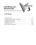
GENERAL
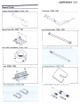
Table
Torque
General
Cable,
Model
Periodic
Before
Wire,
Servicing
Identification
andSpecifications
Maintenance
Locking
and
Hose
Agent
Chart
Routing
INFORMATION
of Contents
...1-2
...1-4
...1-5
...1- 7
...1-9
.1-12
1-1
1-2
GENERAL
INFORMATION
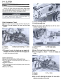
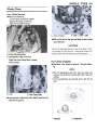
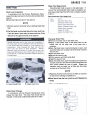
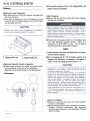
Before Servicing
Before starting to service a motorcycle. careful reading of the applicable section is recommended to eliminate
unnecessary work. Photographs. diagrams. notes. cautions. warnings. and detailed descriptions have been
included wherever necessary. Nevertheless. even a detailed account has limitations, a certain amount of basic
knowledge is also required for successful work.
Especially note the following:
(1} Dirt
Before removal and disassembly, clean the motorcycle. Any dirt entering the engine or other parts will
work as an abrasive and shorten the life of the motorcycle. For the same reason, before installing a new
part, clean off any dust or metal filings.
(2) Battery Ground
Remove the ground ( -) lead from the battery before performing any disassembly operations on the
motorcycle. This prevents:
(a) the possibility of accidentally turning the engine over while partially disassembled.
(b) sparks at electrical connections which will occur when they are disconnected.
(c) damage to electrical parts.
(3) Tightening Sequence
Generally, when installing a part with several bolts, nuts, or screws, start them all in their holes and
tighten them to a snug fit. Then tighten them evenly in a cross pattern. This is to avoid distortion of the
part and/or causing gas or oil leakage. Conversely when loosening the bolts, nuts, or screws, first loosen
all of them by about a quarter of turn and then remove them. Where there is a tightening sequence
indication in this Service Manual, the bolts, nuts, or screws must be tightened in the order and method
indicated.
(4) Torque
When torque values are given in this Service Manual, use them. Either too little or too much torque may
lead to serious damage. Use a good quality , reliable torque wrench.
(5) Force
Common sense should dictate how much force is necessary in assembly and disassembly. If a part seems
especially difficult to remove or install, stop and examine what may be causing the problem. Whenever
tapping is necessary, tap lightly using a wooden or plastic-faced mallet. Use an impact driver for screws
(particularly for the removal of screws held bya locking agent) in order to avoid damaging the screw heads.
(6) Edges
Watch for sharp edges, especially during major engine disassembly and assembly. Protect your hands
with gloves or a piece of thick cloth when lifting the engine or turning it over.
(7) High-Flash Point Solvent
A high-flash point solvent is recommended to reduce fire danger. A commercial solvent commonly
available in North America is Standard solvent (generic name) .Always follow manufacturer and container
directions regarding the use of any solvent.
(8) Gasket, O-Ring
Do not reuse a gasket or O-ring once it has been in service. The mating surfaces around the gasket
should be free of foreign matter and perfectly smooth to avoid oil or compression leaks.
(9) Liquid Gasket, Non-Permanent Locking Agent
Follow manufacturer's directions for cleaning and preparing surfaces where these compounds will be
used. Apply sparingly. Excessive amounts may block engine oil passages and cause serious damage. An
example of a non-permanent locking agent commonly available in North America is Locktite Lock'n Seal
(Blue).
(10) Press
A part installed using a press or driver, such as a wheel bearing, should first be coated with oil on its outer
or inner circumference so that it will go into place smoothly.
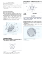
(11) Ball Bearing
When installing a ball bearing, the bearing race which is affected by friction should be pushed by a
suitable driver. This prevents severe stress on the balls and races, and prevents races and balls from being
dented. Press a ball bearing until it stops at the stop in the hole or on the shaft.
GENERAL
INFORMATION
1-3
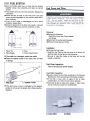
(12) Oil Seal and Grease Seal
Replace any oil or grease seals that were removed with new ones, as removal generally damages seals.
When pressing in a seal which has manufacturer's marks, press it in with the marks facing out. Seals
should be pressed into place using a suitable driver, which contacts evenly with the side of seal, until the
face of the seal is even with the end of the hole.
(13) Seal Guide
A seal guide is required for certain oil or grease seals during installation to avoid damage to the seal lips.
Before a shaft passes through a seal, apply a little high temperature grease on the lips to reduce rubber to
metal friction.
(14) Circlip, Retaining Ring
Replace any circlips and retaining rings that were removed with new ones, as removal weakens and
deforms them. When installing circlips and retaining rings, take care to compress or expand them only
enough to install them and no more.
(15) Cotter Pin
Replace any cotter pins that were removed with new ones, as removal deforms and breaks them.
(16) Lubrication
Engine wear is generally at its maximum while the engine is warming up and before all the rubbing
surfaces have an adequate lubricative film. During assembly, oil or grease (whichever is more suitable)
should be applied to any rubbing surface which has lost its lubricative film. Old grease and dirty oil should
be cleaned off. Deteriorated grease has lost its lubricative quality and may contain abrasive foreign particles.
Don't use just any oil or grease. Some oils and greases in particular should be used only in certain
applications and may be harmful if used in an application for which they are not intended. This manual
makes reference to molybdenum disulfide grease ( MOS2 ) in the assembly of certain engine and chassis
parts. Always check manufacturer recommendations before using such special lubricants.
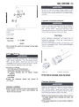
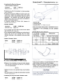
(17) Electrical Wires
All the electrical wires are either single-color or two-color and, with only a few exceptions, must be
connected to wires of the same color. On any of the two-color wires there is a greater amount of one color
and a lesser amount of a second color, so a two-color wire is identified by first the primary color and then
the secondary color. For example, a yellow wire with thin red stripes is referred to as a "yellow/red" wire;
it would be a "red/yellow" wire if the colors were reversed to make red the main color.~
(18) Replacement Parts
When there is a replacement instruction, replace these parts with new ones every time they are removed.
These replacement parts will be damaged or lose their original function once removed.
(19) Inspection
When parts have been disassembled, visually inspect these parts for the following conditions or other
damage. If there is any doubt as to the condition of them, replace them with new ones.
Abrasion
Crack
Hardening
Warp
Bent
Dent
Scratch
Wear
Color change
Deterioration
Seizure
(20) Specifications
Specification terms are defined as follows.
"Standards" show dimensions or performances which brand-new parts or systems have.
"Service Limits" indicate the usable limits. If the measurement shows excessive wear or deteriorated
performance, replace the damaged parts.
1-4
GENERAL
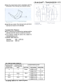
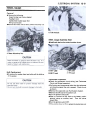
Model
INFORMATION
Identification
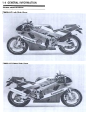
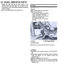
ZX400-H2
Left Side View:
ZX400-H2
Right
Side View:
GENERAl
INFORMATION
1-5
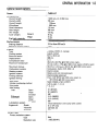
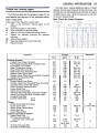
General Specifications
ZX400-H2
Items
Dimensions:
Overall length
Overall width
2035 mm, (I) 2050
705 mm
Overall height
1 1 25mm
Wheelbase
1 395 mm
Road clearance
Seat height
120 mm
765 mm
mm,
163 kg
Dry weight
Curb weight:
Front
Rear
95 kg
94 kg
Fuel tank capacity
16.0 L
Performance:
Braking
1 3.5 m from
distance
Minimum
turning
radius
50 km/h
3.2 m
Engine:
i 4-stroke, DOHC, 4-cylinder
I Liquid-cooled
I 57.0 x 39.0 mm
398 mL
12.1
45.6 kW (62 PS) @12500 r/min (rpm),
(F) 44.2 kW ( -PS) @12500 r/min (rpm) (UTAC's norm)
39.2 N-m (4.0 kg-m, 29.0 ft-Ib) @10000 r/min (rpm)
Carburetors, Keihin CVK-D32 x 4
Electric starter
Battery and coil (transistorized)
Type
Cooling system
Bore and stroke
D isplacement
Compression
ratio
Maximum horsepower
Maximum torque
Carburetion system
Starting system
Ignition system
Timing advance
Electronicallyadvanced
From 12.5° BTDC @1 200 r/min (rpm) to
45° BTDC @6000 r/min (rpm)
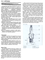
NGK CR9EK or ND U27ETR .
Ignition timing
Spark plug
Cylinder numbering method
Firing order
Valve timing:
Inlet
Open
Close
Duration
Open
Exhaust
.
23° ( BTDC)
65° (ABDC)
268°
57.5° (BBDC)
Close
27.5° (ATDC)
Duration
265°
Forced lubrication
Lubrication system
Engine oil:
Grade
SE or SF class
SAE1 OW -40
3.0 L
Viscosity
Capacity
Drive
Left to right, 1-2-3-4
1 -2-4-3
Train:
Primary
reduction
system:
Type
Reduction
ratio
Gear
2.195 (90/41)
(wet sump with
cooler)
1-6
GENERAL
INFORMATION
Items
ZX400-H2
Clutch type
Transmission
Type
Gear
1 st
ratios:
2nd
3rd
4th
5th
6th
Final
drive
Wet multi disc
6-speed, constant mesh, return shift
2.846 (37/13)
2.055 (37/18)
1.631 (31/19)
1.380 (29/21)
1.240 (31/25)
1 .111 (30/27)
system:
Type
Reduction
Overall
ratio
drive
ratio
Chain drive
3.000 ( 45/15)
7.317 @Top gear
Frame:
Type
Caster
(rake
angle)
Trail
Front
tire:
Size,
type
Mark
Rear tire'
Size, type
Mark
Front suspension
Type
Wheel
travef
Type
Wheel
travel
Rear suspension:
Brake
Front
type:
Rear
Electrical
Tubular, diamond
24°
85mm
120/60 VR17 TUBELESS
DUNLOP K510F
BRIDGESTONE CYROX-17
160/60 VR17 TUBELESS
DUNLOP K510
BRIDGESTONE CYROX-16
Telescopic fork
1 20 mm
Swing arm (uni-trak)
140 mm
Dual discs
Single disc
Equipment:
Battery
Headlight:
Tail/brake light
Alternator:
Type
Bulb
Type
Rated
output
12V10Ah
Semi-sealed beam
Ouartz-halogen 12 V 60/55 W x 2,
12 V 5121 W x 2
Three-phase AC
23 A @10000 rlmin (rpm), 14 V
Specifications are subject to change without notice, and may not apply to every country.
(F)
France Model
(I)
Italy Model
GENERAl
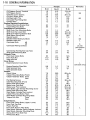
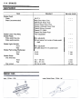
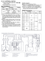
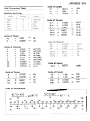
Torque and locking Agent
The following tables list the tightening torque for the
major fasteners requiring use of a non-permanent locking
agent or liquid gasket.
INFORMATION
1-9
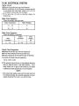
The table below, relating tightening torque to thread
diameter, lists the basic torque for the bolts and nuts. Use
this table for only the bolts and nuts which do not require
a specific torque value. All of the values are for use with
dry solvent-cleaned threads.
Basic Torque for General Fasteners
Letters used in the "Remarks" column mean:
L
: Apply a non-permanent
locking agent to the
threads.
LG : Apply liquid gasket to the threads.
M : Apply molybdenum disulfide grease.
O : Apply an oil to the threads and seating surfaces
: Tighten the fasteners following
the specified
sequence.
SS : Apply silicone sealant.
St : Stake the fasteners to prevent loosening.
R : Replace the part.
Fastener
N-m
Cooling System:
Coolant Drain Plugs (Cylinder)
Thermostatic Housing Bolt (cylinder head)
Thermostatic Fan Switch
Water Temperature Sensor
Water Pump Mounting Bolt
Water Pump Pipe Mounting Bolt
Radiator Hose Clamp Bolts
Radiator Horse Fitting Mounting Bolt (cylinderl
Radiator Fan Mounting Bolt
Engine Top End:
Cylinder Head Cover Bolts
Cylinder Head Cover Woodruff Plug Mounting
Camshaft Chain Guide Bolt (Rear)
Chain Tensioner Mounting Bolt
Rocker Shaft Plug
Upper Chain Guide Bolt
Inlet Pipe Mounting Bolt (carburetor holder)
Outlet Pipe Mounting Bolt (cylinder head)
Camshaft Cap Bolts
Cylinder Head Bolts:
8 mm
6mm
Clutch
Clutch Cover Mating Surfaces
Clutch Cover Bolts
Clutch Cover Damper Bolts
Clutch Hub Nut
Clutch Spring Bolts
Engine Lubrication
System:
Engine Drain Plug
Oil Hose Mounting Bolt
(cylinder head, crankcase)
Oil Filter
Oil Filter Mounting Bolt
Oil Pressure Relief Valve
Remarks
Torque
kg-m
ft-Ib
8 .8
8 .8
18
7 .8
8 .8
8 .8
2 .0
8 .8
3 .4
0.90
0.90
1.8
0.80
0.90
0.90
0.2
0.90
0.35
78 in-Ib
78 in-Ib
13
69 in-Ib
78 in-Ib
78 in-Ib
17 in-Ib
78 in-Ib
30 in-Ib
9.8
1.0
7.0
25
25
12
2.5
0.90
1.0
1.2
0.90
0.90
1.2
2.5
1.2
18.0
78 in-Ib
7.0
8.5
78 in-Ib
78 in-lI:Y
8.5
18.0
8.5
9.8
9.8
130
12
0.90
1.0
13.5
1.2
78 in-Ib
7.0
98
8.5
20
2.0
14.5
8.8
9.8
12
8.8
8.8
12
L
ss
L
ss
L
ss
8.8
9.8
29
15
0.90
1.0 or
hand-tight
3.0
1.5
L (two
bolts)
L
R
78 in-Ib
7.0
R
22
11.0
L
1-10
GENERAl
INFORMATION
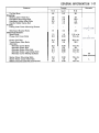
Fastener
Oil Pressure Switch Terminal
Oil Pressure Switch
Oil Pump Cover Screws
Oil Plug (Right, M18)
Oil Plug (Left, PT%)
Oil Cooler Pipe Fitting Bolt
Oil Pan Bolts
Engine Removal/Installation:
Engine Mounting Bracket Bolt
Engine Mounting Bolts
Cra n kshaft/T ransm ission :
Shift Drum Cam Mounting Bolts
Shift Drum Set Lever Bolt
Shift Drum Bearing Retainer Bolt
Shift Return Spring Bolt
Neutral Switch
Breather Plate Mating Surfaces
Breather Plate Bolt
Crankcase Bolts
Cl>6
Cl>8
Crankcase Mating Surfaces
Connecting Rod Big End Cap Nuts
Shift Pedal Mounting Bolt
Wheels/Tires:
Front Axle Clamp Bolts
Front Axle Nut
Rear Axle Nut
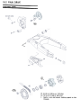
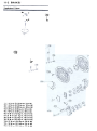
Final Drive:
Engine Sprocket Cover Bolts
Remarks
Torque
N-m
kg-m
1.5
0.15
1.5
0.45
1.5
1.75
1.2
1.2
13 in-Ib
11.0
39 in-Ib
11.0
12.5
8.5
8.5
30
36
3.1
22
27
12
1.2
0.90
0.90
2.0
1.5
8.5
78 in-Ib
78 in-Ib
14.5
11.0
1.0
1.2
2.8
7.0
8.5
20
15
4.4
15
17
12
12
8.8
8.8
20
15
3.7
~
ss
ss
L
L
ss
9.8
12
27
L
s
LG, SS
(one portion
only)
25
25
20
110
110
2.6
2.5
19
18
2.0
14.5
11.0
80
11.0
80
L
(one
Engine Sprocket Plate Bolt
Rear Sprocket Nuts
Rear Sprocket Studs
Brakes:
Bleed Valves
Caliper Mounting Bolts (Front)
Caliper Assembly Bolts: Front
Rear
Pad Spring Screws
Disk Mounting Bolt (Front)
Brake Hose Banjo Bolts
Brake Lever Pivot Bolt
Brake Lever Pivot Locknut
Front Brake Light Switch Mounting Screw
Brake Pedal Mounting Bolt
Rear Master Cylinder Rod Locknut
Caliper Mounting Bolts ( Rear)
Rear Master Cylinder Mounting Bolts
Torque Link Nut:
Front
Rear
Suspensions:
Front Fork Clamp Bolts (Upper, Lower)
Front Fork T op Bolt
Piston Rod Nut
Front Fork Bottom Allen Bolts
Rear Shock Absorber Spring Adjuster Locknut
Rear Shock Absorber Mounting Nuts
Swing Arm Pivot Shaft Nut
Rocker Arm Nuts
9.8
1.0
7.0
74
7.5
54
bolt
L
7.8
34
21
32
2.9
27
25
1.0
5.9
1.2
25
18
25
23
34
25
0.80
3.5
2.1
3.3
0.30
2.8
2.5
0.10
0.60
0.12
2.5
1.8
2.5
2.3
3.5
2.5
69 in-Ib
25
15
24
26 in-Ib
20
18.0
9 in-Ib
52 in-Ib
10 in-Ib
18.0
13.0
18.0
16.5
25
18.0
20
23
15
39
88
49
110
49
2.0
2.3
1.5
4.0
9.0
5.0
11.0
5.0
14.5
16.5
11.0
29
65
36
80
36
L
only)
GENERAl
Fastener
Side Stand Bracket Bolts
Electrical System:
Spark Plugs
Pickup Coil Cover Bolts
Pickup Coil Bolt
Timing Rotor Allen
Alternator
Alternator Cover
Alternator Rotor
Alternator Stator
Alternator Stator
Alternator Cover
49
Bolts
Bolt
Allen Bolt
Lead Clamp Bolt
Mating Surfaces
ft-Ib
5.0
36
23
31
3.2
23
1.3
0.90
113 in-Ib
78 in-Ib
0.65
2.5
56 in-Ib
18.0
0.90
8.0
0.85
0.85
73 in-Ib
58
74 in-Ib
74 in-Ib
9.8
13
8.8
6.4
Bolts
kg-m
4.0
2.6
1.0
2.3
39
25
25
8.8
78
8.3
8.3
29
19.0
7.0
16.5
ss
(three
Starter Motor Mounting Bolts
Starter Motor Clutch Allen Bolt
Battery Ground Lead Bolt (Crankcase)
1-11
Remarks
Torque
N-m
Tie- Rod Nuts
Steering:
Steering Stem Head Nut
Handlebar Mounting Bolts
Handlebar Holder Allen Bolts
Handle Holder Clamp Bolt
Frame:
Fairing Inner Cover Mounting Screws
INFORMATION
8.8
34
8.8
0.90
3.5
0.90
78 in-Ib
25
78 in-Ib
portions)
L
1-12
GENERAL
INFORMATION
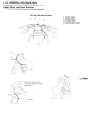
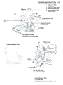
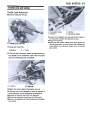
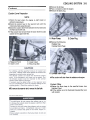
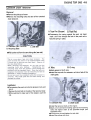
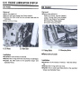
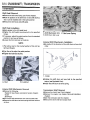
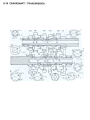
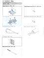
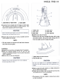
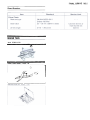
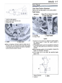
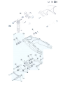
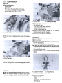
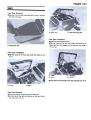
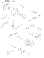
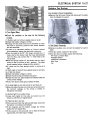
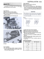
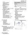
Cable. Wire. and Hose Routing
Run
the
cable
into
the
clamp.
1. Clutch
Cable
2. Choke
Cable
3. Throttle
Cable
4. Speedometer
Cable
/Clamp
~
GENERAL
INFORMATION
1-13
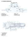
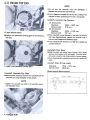
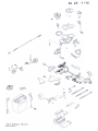
1. Battery Vent Hose
Battery
Fuel
(Transparent)
2. Battery Vent Hose (Black)
3. Fuel Tank Breather Hose
4. Coolant Reservoir Tank
Breather Hose
Tank
/
/
0-..
/
@
~
~-L/
/~~
/f"-
Rear
Fender
Coolant Reservoir Tank
..::;..,.I
,
(front)
Joint
.-~
~~
Run
the
the
'A
~
under
pipe.
(
~
~
cross
horse
>~Iamp
/1\-
.;,~;,;'"
"
,,'
,
.~...
~
@
Run the horses through
backside of the swing arm
pivot,
Battery
Case
~
View Looking at Top
4
7
3
0
'If
"
/
-I/
Coolant
Reservoir
' v/
,1
"ljt
~
-
Tank \
~
~
To
~
~ "
'
-
Carburetor
I
Pull the hoses down
out of the lower fairing
5. Coolant Reservoir Hose
6. Oil Cooler Pipe
7. Fuel Hose (from Fuel Pump to Carburetor)
1-14
GENERAL
INFORMATION
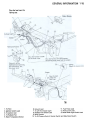
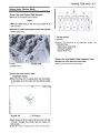
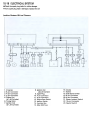
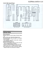
View Looking at Front
1 .Main
Harness
2. To Right
Grip Switch
3. To Left Grip Switch
4. To Water
5. Starter
Temperature
Motor
Sensor
lead
10. To Oil Pressure Switch,
Neutral Switch and
Side Stand Switch
11. Alternator Lead
12. Battery ( + ) Lead
13. Rear Harness
6.
7.
8.
9.
Battery ( -) Lead
Ground Lead
To Ignition Coil (#1, #4)
To Ignition Coil (#2, #3)
GENERAL
INFORMATION
1-15
Run the lead over the
fairing stay.
@
1.ToHorn
2. Ignition Switch Lead
3. To Ignition Coil
4. To Radiator Fan
5. Water Temperature Sensor
6. Ground Lead
7. To Left Turn Signal Light
8. Radiator Fan Switch Lead
11. Fuel Pump Lead
12. Pickup Coil Lead
13. Rear Brake Light Switch Lead
9. Main Harness
10. To Oil Pressure Switch, Neutral Switch and Side Stand Switch
1-16
GENERAL
INFORMATION
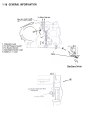
To Main Harness
Run the lead inside
of the
~
water
-
1 f
"'"--'
pump.
1
,
-
0)-
t m
~v
)~
~
1. Alternator
]1
Lead
2. To Oil Pressure
Switch
3. To Neutral
Switch
4. Side Stand
Switch
5. Battery
( -)
Lead
0--
Lead
"
/
Clamp
Side Stand Switch
(QJ:l
--
~
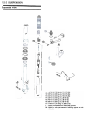
FUEL SYSTEM
Table
Specifications
Special
Exploded
Throttle
Surge
Choke
Air
Carburetors
Fuel
Fuel
Tools
Throttle
Choke
Tank Cable
Surge
Air
Oil
Service
Element
Carburetor
Idle Cleaner
Carburetor
Installation
Removal
Fuel
Removal
Installation
View
Grip
Cleaner
Draining
Speed
Tank
Pump
Tank
Cable
,
Cable
and
Fuel Cleaning
and
Pump
Filter
of
AdjustmentAdjustment
Cables
Adjustment
Installation
Removal
Disassembly
Housing
RemovaJ
Level
Inspection
InspectionInspection
Filter
,
Adjustment
Removal
/
Assembly
'
,
,
Contents
..2-2
..2-4
...2-4
..2-5
..2-5
..2-6
...2-6
...2-6
...2-6
...2-7
...2-7
...2- 7
...2-7
...2-8
...2-8
...2-8
...2-9
...2-9
...2-9
...2-9
.2-10
.2-10
.2-10
.2-10
.2-10
.2-11
.2-11
.2-11
2-1
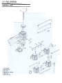
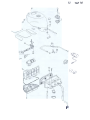
2-2
FUEL
Exploded
SYSTEM
View
2-4
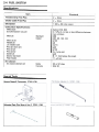
FUEL
SYSTEM
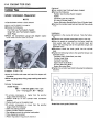
Specifications
Item
Throttle
Standard
Grip Free Play
2 -3mm
Choke Cable Free Play
2 -3mm
Idle Speed
1 200
Carburetor
:t 50 r/min
(rpm)
Specifications:
Make/type
Synchronization
vacuum
Main jet
Standard
Option
Main air jet
Needle jet
Jet needle mark
Pilot jet (slow jet)
Pilot air jet
Pilot screw
Starter jet
Service fuel level
Float height
Keihin/CVK-D32
2.7 kPa (2 cm Hg) or less difference between
two cylinders
#98
#92, 95, 100' 102
#100
#6
N77C
#35
#120
2'14(turns out)
I #45
8 :t 1 mm below the mark
11 %2 mm
Air Cleaner:
Air cleaner element oil
Grade
SE or SF class
Viscosity
SAE 30
Special Tools
Vacuum
Gauge
& Tachometer:
57001-1291
Carburetor Drain Plug Wrench, Hex 3: 57001 -1269
~
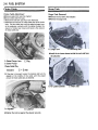
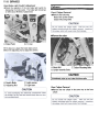
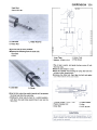
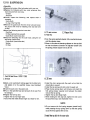
FUEL SYSTEM
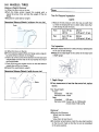
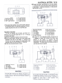
Throttle
Grip and Cables
Throttle
Cable
.Check
throttle
Adjustment
grip
free
play.
Grip Free Play
Standard:
*If
.Tighten
Accelerator
B.
Adjuster
grip opened.
mm
the free play is incorrect, loosen the locknut and turn
the adjuster of the accelerator cable until the proper
amount of throttle grip play is obtained.
A. Locknut
*If
2 -3
A.
Cable
Co Locknut
Do Decelerator
Cable
.Loosen all the adjuster and slide both throttle cables at
the carburetor to obtain the specified free play.
.Tighten the locknuts.
.Check that the throttle linkage lever stops against the
idle adjusting screw with the throttle grip released and
stops against the carburetor stopper with the throttle
A. Throttle Grip Free Play
Throttle
2-5
B. Adjuster
the locknut against the adjuster securely.
the play can not be adjusted by using the adjuster at
the throttle grip, use the adjusters at the carburetors.
.Remove the fuel tank (see Fuel Tank Removal).
.Remove the surge tank (see Surge Tank Removal).
.Screw in the adjuster fully at the throttle grip and tighten
the locknut.
2-6
FUEL
SYSTEM
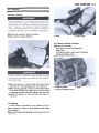
Choke Cable
Surge Tank
Choke Cable Adjustment
.Remove surge tank (see this chapter).
.Check choke cable free play.
O Remove the fuel tank (see Fuel Tank Removal).
O Determine the amount of choke cable play at the choke
lever. Pull the choke lever until the starter plunger lever
at the carburetor contacts with the starter plunger; the
amount of choke lever lower end travel is the amount
of choke cable play.
Surge
Tank
Removal
.Remove
the fuel tank (this chapter).
.Remove
the surge tank.
A.
Surge
B.
Tank
Mounting
Bolt
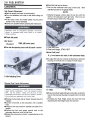
.Install the air cleaner element so that the mesh side faces
the carburetor.
A. Starter
Plunger
B. Starter
Plunger
c. Play
Lever
Choke Cable Play
Standard:
*If
2-3mm
the play is incorrect, loosen the locknut and turn the
adjuster at the middle of the cable until the proper
amount of choke cable play is obtained.
A.
B. Locknut
A. Adjuster
.Tighten
the locknut
against
the adjuster
securely.
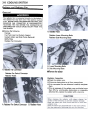
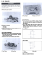
Air
Cleaner
Element
B.
Mesh
Side
FUEL SYSTEM
Air Cleaner
Element Cleaning
.Remove the surge tank (see this chapter).
.Take out the air cleaner element.
A.
Air
B.
Plug
Cleaner
.Remove
Housing
Drain
Hose
Removal
the following.
Fuel Tank
(see Fuel Tank
Removal)
Serge Tank
Air Cleaner
Crankcase
.Remove
A.
Air
Cleaner
Element
B.
Element
Element
Breather
the air cleaner
(see Element
Cleaning)
Hose
housing.
Mesh
.Wash the element in a bath of high-flash point solvent
and then dry it with compressed air or by shaking it.
.After cleaning, saturate a clean, lint-free towel with SE
or SF class SAE30 oil and apply the oil to the element
by tapping the foam side of the element with the towel.
.Install
the element so that the mesh side faces the
carburetor.
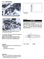
Oil Draining
A drain hose is connected to the bottom of the air
cleaner housing, to drain oil accumulated at the bottom
of the housing.
.Drain oil by taking off the plug at the lower end of the
drain hose.
A. Plugs and Bolts
B. Crankcase Breather Hose
c. Bolts
2-7
2-8
FUEL
SYSTEM
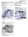
.Check
Carburetors
OTurn
the fuel
level as shown.
out the carburetor
drain
until the fuel level in the gauge
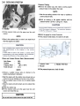
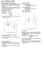
Idle Speed Adjustment
.Start the engine and warm it up thoroughly.
.Turn the handlebar from side to side while idling the
engine.
idle speed varies, the throttle cables may be poorly
routed or they may be damaged.
.Correct any problem before operating the motorcycle.
*If
.Check
idle
plug
a few
turns.
Wait
settles.
NOTE
OKeeping the gauge vertical align the top line with the
mark on the carburetor body right side. Then turn out
the drain plug to feed fuel to the gauge.
speed.
Idle Speed
Standard:
.Turn
1200
:t50
r/min
(rpm)
the idle adjusting screw until idle speed is correct.
A. Fuel Level Mark
B. Fuel Level Gauge:
57001 -1017
Service Fuel level
8 :t1 mm below the mark on the carburetor body
.To adjust the fuel level, remove the float bowl, and bend
the tang on the float arm to change the float height.
A. Idle Adjusting Screw
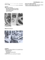
ServiceFuel LevelAdjustment
A. Float
.Remove
the fuel tank and air cleaner housing (see this
chapter).
.Connect
a fuel tank to the carburetors with a suitable
hose.
.Prepare a fuel hose (6 mm in diameter and 300 mm in
length).
.Connect
the fuel level gauge (special tool) to the
carburetor float bowl with the fuel hose.
.Situate the motorcycle so that it is perpendicular to the
ground.
B. Tang
.Measure the float height tilting the carburetor so that the
tang on the float just touches the needle rod in the float
valve.
O Increasing the float height lowers the fuel level and
decreasing the float height raises the fuel level.
FUEL SYSTEM
~
2-9
/
Carburetor Disassembly / Assembly
~
Float Height
Standard:
11 :t2 mm
NOTE
0 Do not push the needle rod in during the float height
measurement.
Carburetor Removal
CD
.Remove the following.
Fuel Tank (see Fuel Tank Removal)
Surge Tank (see Surge Tank Removal)
Air Cleaner Housing (see Air Cleaner
Removal)
Idle Adjuster
Fuel Hoses
.Loosen
the carburetor
carburetors.
Carburetor
.Install
Housing
*If
clamps
and
remove
the needle jet is damaged,
replace
the carburetor
the
Carburetor Inspection
Installation
the holder
clamps
screw
position
and
the
Engine
Top End chapter).
as shown
screw
being
head
careful
of the
direction
(see
.Slide the starter plunger lever right to left to check that
the starter plungers move smoothly and return with
spring tension.
*If
the starter plungers do not work properly, replace the
carburetors.
2-10
FUEL SYSTEM
.Turn the throttle cable lever to check that the throttle
butterfly valves move smoothly and return by spring
tension.
* If the throttle valves do not move smoothly. Replace the
carburetors.
.Check that the O-rings on the float bowl and pilot
screws and the diaphragm on the vacuum piston are in
good condition.
* If any of the O-rings or diaphragms are not in good
condition, replace them.
.Check the plastic tip of the float valve needle. It should
be smooth without any grooves, scratches, or tears.
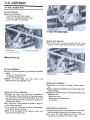
Fuel Pump and Filter
Removal
.Remove
the following.
Right Side Cover
(see Frame chapter)
Fuel Hoses
.Disconnect
the pump
.Remove
1.
Plastic
2.
Valve
Tip
Needle
3. Rod
4. Valve
Needle
Wear
*If the plastic tip is damaged, replace the needle.
.Check the tapered portion of the pilot screw for wear
or damage.
the fuel pump
lead connector.
and filter.
Installation
.Connect
the fuel hoses.
O Install the fuel filter so that the arrow on it shows the
fuel flow from the fuel tank to the fuel pump.
O Be sure to route the hoses so that they will not be
kinked or stretched.
Fuel
Pump
Inspection
Refer to the Electrical
System
chapter.
Fuel Filter Inspection
.Visually inspect the fuel filter according to the Periodic
Maintenance Chart (see General Information chapter).
*If the filter is clear with no signs of dirt or other
contamination, it is OK and need not be replaced.
1. Pilot Screw
*If
2.
Tapered
Portion
*If
the filter is dark or looks dirty, replace it. Also, check
the rest of the fuel system for contamination.
the pilot screw is worn or damaged on the tapered
portion, it will prevent the engine from idling smoothly.
Replace it.
A. Arrow
Mark
B. Blow
FUEL SYSTEM
Installation
Fuel Tank
.Install
Removal
.Turn
the fuel
tap to the OFF position
to stop
the fuel
flow.
.Remove the following.
Front Seat (see Frame chapter)
Side Cover Assembly
Fuel Tank Mounting Bolts
Fuel Tap with Fuel Hoses left installed and Fuel Hose
to the carburetor removed
Air Duct Clamp
A.
Mounting
Bolts
B.
Fuel
Tap
NOTE
0 To take the air ducts out, remove the duct pawls from
the inside of the fuel tank.
.Remove
the fuel tank.
the fuel tank hoses.
2-11
COOLING
Table
Specifications
Exploded
View
Special
Sealant
Coolant
Coolant
Water
Coolant
Water
Pressure
Installation
Removal
Radiator
Pump
Pump
and
Radiator
Removal
Radiator
Thermostat
ToolFlow
Inspection
Installation
Removal
,'
Level
Chart
Draining
Filling
Testing
Inspection
Inspection
,
..
Radiator
Inspection
Cap
Fan
Inspection
..
.
,
SYSTEM
of Contents
..3-2
..3-3
..3-3
..3-3
..3-4
..3-5
..3-5
..3-5
..3-5
..3-6
..3-7
...3-7
...3-7
...3-7
...3-8
...3-8
...3-8
...3-9
.3-10
.3-10
.3-10
.3-10
3-1
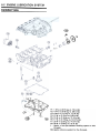
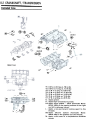
3-2
COOLING
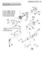
Exploded
SYSTEM
View
~tJ'
c:::::;,~
~
,
"'@
@)
@
>@
CD
""
T1
T2
T3
T4
T5
l
" "'
"'
: 2.0 N-m (0.2 kg-m. 17 in-Ib)
: 3.4 N-m (0.35 kg-m. 30 in-Ib)
: 7.8 N-m (0.8 kg-m. 69 in-Ib)
: 8.8 N-m (0.9 kg-m. 78 in-Ib)
: 18 N-m (1.8 kg-m.13 ft-Ib)
: Apply a non-permanent
threads.
SS: Apply silicone sealant
locking
agent
to the
to the threads.
~
~
COOLING
SYSTEM
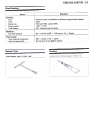
Specifications
Standard
Items
Coolant:
Type
Color
Mixed
ratio
Freezing point
Total amount
Permanent type of antifreeze for aluminum engines and radiators
Green
Soft water 50%, coolant 50%
-35°C ( -31°F)
2.3 L (reservoir tank full level)
Radiator:
Cap
relief
pressure
Thermostat:
Valve opening temperature
Valve full opening lift
Special Tool
Socket Wrench, Hex 8: 57001 -1 268
93 -123
kPa (0.95 -1 .25 kg/cm2, 14 -18
80.0 -84.0°C
(176 -183°F)
Not less than 6 mm @95°C (203°F)
Sealant
psi)
3-3
3-4
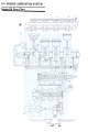
COOLING
Coolant
SYSTEM
Flow Chart
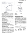
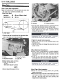
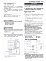
When the engine is cold, the thermostat is closed so that the coolant flow is restricted through the small hole
(air hole) on the thermostat, causing the engine to warm up more quickly.
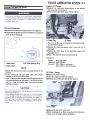
COOLING
.Remove
Coolant
.Place
SYSTEM
3-5
the fairings.
a container
.Remove
under the engine.
the drain plug.
Coolant Level Inspection
NOTE
OCheck the level when the engine is cold
ambient temperature).
(room
or
.Check the coolant level in the reservoir tank with the
motorcycle held perpendicularly.
.Check the coolant level from between the fuel tank and
the flame at the left side.
* If the coolant level is lower than the lower level line, add
coolant to the upper level line.
A. Water Pump
B.
Drain
Plug
.Remove the following.
Radiator Cap
Cylinder Drain Plugs
A. Reservoir
B. Upper
Tank
Level
Co Lower
Do Mounting
Level
Bolt
A.
Cylinder
.The
coolant
Coolant
.Tighten
.To
remove
the reservoir
Coolant Draining
tank, remove
the fuel tank.
Drain
Plugs
will drain from the radiator
and engine.
Filling
the drain plugs to the specified
torque (see
Exploded View).
.Fill the radiator up to the thermostat housing filler neck
with coolant.
3-6
COOLING
SYSTEM
Pressure
.Remove
pressure
T esting
the radiator
cap,
and
tester on the radiator
install
a cooling
system
filler neck.
NOTE
0 Wet the cap sealing surfaces with water or coolant to
prevent pressure leaks.
.Build
up pressure in the system carefully until
pressure reaches 123 kPa (1.25 kg/cm2, 18 psi).
A. Radiator
B. Filler Neck
o Fill the reservoir tank up to the upper level line with
coolant.
.Watch the gauge for at least 6 seconds.
*If the pressure holds steady, the system is all right.
NOTE
o Pour in the coolant slowly so that it can expel the air
from the engine and radiator.
Water and Coolant Mixture Ratio (Recommended)
Soft Water
Coolant
Freezing Point
Total Amount
50%
50%
-35°C ( -31°F)
2.3 L
coolant
a suitable
manufacturel
mixture
Pressure
Adapter
*If
NOTE
0 Choose
1.
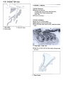
2.
ratio
by
referring
to the
s directions.
OStart the engine with the radiator cap removed and run
it until no more air bubbles can be seen in the coolant.
OTap the radiator hoses to force any air bubbles caught
inside.
O Stop the engine and add coolant up to the radiator filler
neck.
.Install the radiator cap.
.Fill the reservoir tank up to the upper level line with
coolant and install the cap.
CAUTION
Do not add more coolant above the upper level line.
3. Radiator Filler Neck
Tester
the pressure
drops soon,
check
for leaks.
the
COOLING
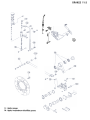
Water
plug.
.Remove the following.
Shift Lever
Engine Sprocket Cover
Radiator Hose Clamp on Water Pump
Water Pipe
Water Pump Mounting Bolts(2)
Water
.Pull
B.
Pump
the
radiator
water
3-7
Water Pump Pipe Mounting Bolt
Radiator Hose Clamp Bolt
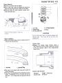
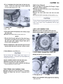
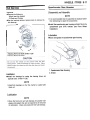
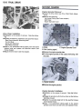
.Apply
a non-permanent locking agent to the engine
sprocket cover bolt (one bolt only -see
Final Drive
Pump
Removal
.Remove the fairings.
.Drain the coolant by removing the water pump drain
A.
SYSTEM
pump
out
Mounting
of the
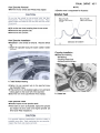
Water Pump Inspection
.Check the drainage outlet passage at the bottom of the
water pump body for coolant leaks.
* If the mechanical seal is damaged, the coolant leaks
through the seal and drains through the passage.
Replace the water pump unit.
Bolts
crankcase
and
the
hose.
! nsta!!ation
.Install
the water pump with the water pump cover
removed.
.Turn the water pump impeller so that the water pump
shaft slot fits the oil pump shaft projection.
A. Water Pump Shaft
B.
Oil
Pump
Shaft
.Install the water pipe.
.Tighten the following bolts to the specified torque (see
Exploded View).
Water Pump Mounting
Bolts
chapter).
.Install the water pump cover.
.Fill the coolant (see Coolant Filling).
A. Drainage Outlet Passage
(at the bottom of the pump body)
3-8
COOliNG
Radiator
SYSTEM
and Radiator
Fan
Removal
The radiator
fan is connected
directly
to the battery.
The radiator
fan may start even if the ignition
switch
is off. NEVER TOUCH THE RADIATOR FAN UNTIL THE
RADIATOR
FAN CONNECTOR
IS DISCONNECTED.
TOUCHING
THE FAN BEFORE THE CONNECTOR
IS
DISCONNECTED
COULD CAUSE INJURY FROM THE
FAN BLADES.
.Remove
the following.
A.
Fairings
Fuel Tank (see Fuel System chapter)
Coolant (drain: see Water Pump Removal)
Baffle Plate
Radiator Fan Connector
Radiator
Hose
Radiator Lower Mounting Bolts
Radiator Side Mounting Bolts
A. Lower Mounting Bolts
B. Side Mounting Bolts
A.
Radiator
Fan
Connector
.Remove
the
radiator
Radiator Fan Switch Connector
Radiator Hoses
Radiator Inspection
.Check the radiator core.
*If there are obstructions to air flow, remove them.
*If
the corrugated fins are deformed, carefully straighten
them.
* If the air passages of the radiator core are blocked more
than 20% by unremovable obstructions or irreparably
deformed fins, replace the radiator with a new one.
A. Radiator
Fan
Switch
Connector
B.
Radiator
Hose
COOLING
1.
Steam
Gun
Running
1.
Direction
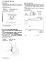
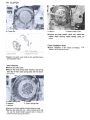
Radiator Cap Inspection
.Check the condition of the top and bottom valve seals
of the radiator cap.
* If anyone of them shows visible damage, replace the
cap.
Pressure
Tester
.Install
Valve
Valve
3. Valve Spring
Seal
Seal
the cap on a cooling
system
pressure
tester.
NOTE
0 Wet the cap sealing surfaces with water or coolant to
prevent pressure leakage.
Cap
Radiator Cap Relief Pressure
*If
1 .Bottom
Radiator
3-9
.Watching
the pressure gauge, pump the pressure tester
to build up the pressure. The cap must open at the relief
pressure (the gauge pointer flicks down). Also the cap
must hold any pressure less than the relief pressure for
at least 6 seconds.
Standard:
2. Top
2.
SYSTEM
93 ~ 123 kPa
(0.95 -1.25 kg/cm2, 14 -18
psi)
the cap cannot hold the specified pressure, or if it
holds too much pressure, replace it with a new one.
3-10
COOLING
SYSTEM
Thermostat
Removal
.Remove the fairing and the side cover assembly.
.Drain coolant (cylinder head, cylinder).
.Remove the following.
Carburetor (see Fuel System chapter)
Hose (Thermostat Housing)
Mounting Bolts
Water Temperature Sensor Connector
.Remove the thermostat housir,g on the cylinder.
.Remove the thermostat from the housing.
1 .Thermostat
*If
2. Thermometer
the measurement
is out of the specified
the thermostat.
Thermostat
80 -84°C
A.
Housing
B.
Mounting
Bolt
I nsta!lation
.Install the thermostat noting the following.
.Install the thermostat so that the stay faces outside.
.Be sure to install the O-ring on the housing.
.Add coolant (see Coolant Filling).
Inspection
.Remove
the thermostat and inspect the thermostat
valve at room temperature.
*If the valve is open, replace the valve with a new one.
.To
check valve opening temperature, suspend the
thermostat in a container of water and raise the
temperature of the water.
Valve Opening Temperature
(176 -183°F)
range, replace
ENGINE
Table
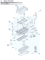
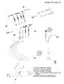
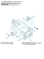
Exploded View
,
,
4-2
Specifications
4-4
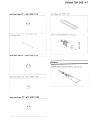
Special Tools
4-6
Sealant
,
4- 7
Cylinder Head Cover
4-8
Removal
4-8
Installation
4-8
Camshaft Chain Tensioner
4-9
Removal
4-9
Installation
4-9
Camshaft
4-10
Camshaft Removal
4-10
Camshaft Installation
4-11
Camshaft, Camshaft Cap Wear
4-12
Camshaft Chain Wear
4-12
Rocker Arm, Rocker Shaft
4-13
Rocker Arm and Rocker Shaft Removal
4-13
Rocker Arm and Rocker Shaft
Installation Notes
4-13
Rocker Arm and Rocker Shaft Inspection Note 4-13
Cylinder Head
4-14
Cylinder Compression Measurement
4-14
Removal
4-14
Installation
4-14
Valves
4-15
TOP END
4-1
of Contents
Valve
Valve
Valve
Valve
Measure
Cylinder,
Carburetor
Muffler
Cylinder
Cylinder
Piston
Cylinder
Piston
Clearance
Removal
Guide
Installation
Seat
Seat
(Wobble
Piston
Installation
Removal
Removal
Installation
Valve-to-Guide Width
Outside
Repair
Pistons
Wear
Removal
Installation
Ring,
Ring
Wear
Removal
Installation
Holders
Removal
Installation
Method)
Adjustment
Piston
End
Inspection
(Valve
Diameter
Ring
,
Gap
..4-15
..4-16
..4-16
..4-16
..4-16
..4-17
..4-17
..4-17
Lapping)
Clearance
,
Groove
,
Wear
.4-19
.4-20
.4-20
.4-20
..4-21
..4-21
..4-21
..4-22
..4-22
..4-22
..4-23
..4-23
..4-23
..4-23
..4-23
..4-23
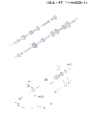
ENGINE
TOP END
4-3
@
~
~r
c
.~
"
.,
:"
~"
~"
~
~
~
~
~
,
@
0
\\
~c:::c
~ ""'
,~
e
~
~
~
B
~
0
~
>@
~
\
~\
~
~
~
I
@
~-~
\
e
"'~
P"
--, p. ~
, ~
I ~ !
~
)
~oq;;:::::
,~
mil'
J@
@ e
~ t
~
1
~
A
/
~
/
~
'@
/\
CD
T1:
T2:
T3:
T4:
L:
,
8.8 N-m (0.9 kg-m. 78 in-Ib)
9.8 N-m (1.0 kg-m. 7.0 ft-Ib)
12 N-m (1.2 kg-m. 8.5 ft-Ib)
25 N-m (2.5 kg-m. 18.0 ft-Ib)
Apply a non-permanent
locking agent to the
threads.
M: Apply molybdenum disulfide grease.
88: Apply silicone sealant to the threads.
~
4-4
ENGINE
TOP END
Specifications
Item
Standard
Service
Limit
Camshaft:
Cam
height
Camshaft,
Inlet
31 .778 -31
Exhaust
31.469
camshaft
B
journal
diameter:
A
B
Camshaft
bearing
Camshaft
runout
Camshaft
chain
Cylinder
31 .68 mm
mm
31 .37 mm
cap clearance
A
Camshaft
.918 mm
-31.609
inside
diameter
0.028 -0.071 mm
0.0780.121 mm
23.950 -23.972
mm
23.900 -23.922
mm
24.000 -24.021
mm
0.16
mm
0.21
mm
23.92
mm
24.08
mm
0.1
20-link
127.0-
length
127.4 mm
mm
23.87
mm
TIR
1 28.9
mm
Head:
Cylinder
compression
(Usable
range)
1 686 -1
079 kPa
(7.0 -11.0
kg/cm2, 99 -156
@330 r/min (rpm)
psi)
Cylinder head warp
0.05
mm
36.4
mm
0.25
mm
0.35
mm
Valves:
Valve
clearance
Inlet
Exhaust
Valve spring free length
Valve head thickness:
Inlet
Exhaust
Valve stem bend
Valve seat cutting angle
Valve seat surface:
Width:
Inlet
Exhaust
Outside diameter:
Inlet
Exhaust
0.120.17 mm
0.160.21 mm
38.2 mm
0.5mm
0.7 mm
0.02 TIR or under
45°, 32°, 60°
0.5 -1 .0 mm
0.5 -1 .0 mm
21 .5 -21 .7 mm
18.518.7 mm
Camshaft Journal Diameter
0.05
mm
----
TIR
ENGINE
Item
Standard
TOP END
Service
Limit
Valve/valve guide clearance
(wobble method):
Inlet
Exhaust
0.031 -0.140
mm
0.0850.180 mm
0.34
mm
0.41
mm
3.975 -3.990
3.955 -3.970
4.000 -4.012
3.96
mm
3.94
mm
4.08
mm
mm
57.10
mm
mm
56.79
mm
Valve stem diameter
Inlet
Exhaust
Valve guide inside diameter
Cylinder.
Cylinder
mm
mm
mm
Piston:
inside diameter
~ 57.000
Piston diameter
Piston/cylinder
clearance
56.942
2
-56.957
0.043 -0.070
+ 0.5 mm
0.030 -0.070
Oversize piston and rings
Piston ring/groove
-57.01
clearance
mm
mm
0.17
mm
0.70
mm
0.80
mm
Piston ring end gap:
Top
Second
Valve Head
0.20 -0.40
0.35 -0.50
mm
mm
Valve Stem Bend
4-5
4-6
ENGINE
TOP END
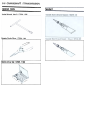
Special Tools
Compression Gauge: 57001 -221
Compression
Gauge Adapter,
M10 X 1.0:
57001-1317
Rocker Arm Holder: 57001 -1270
Valve Guide Reamer, <!>4: 57001-1274
Valve Spring Compressor Assembly:
Valve Spring
Compressor
Adapter,
57001-241
<1>21: 57001-1272
Valve Seat Cutter Holder, <!>4: 57001-1275
Valve Seat Cutter, 45° -4>24.5:
57001 -1113
ENGINE
Valve Seat Cutter,
3L
-<t>25:
57001-1118
Valve Seat Cutter, 60. -<f>30: 57001-1123
Sealant
Valve Seat Cutter, 32.-
<!>22: 57001 -1206
TOP END
4-7
4-8
ENGINE
TOP END
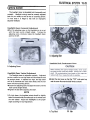
Cylinder Head Cover
Removal
.Remove the following.
Fuel Tank (see Fuel System chapter)
Air Cleaner Housing (see Fuel System chapter)
Ignition Coils
Throttle Cable
Choke Cable
Baffle Plate
1.
A.
Baffle
.Remove
cover.
A. Bolts
Plate
Bolt
the cylinder head cover bolts and take off the
B. Cylinder Head Cover
I nsta!lation
.Replace the head cover gasket with
new one if it is
damaged.
.Apply silicone sealant to the cylinder head as shown.
.Tighten
the cover bolts to the specified torque (see
Exploded View).
Silicone
Sealant
Applied
Areas
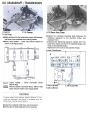
ENGINE
Camshaft
TOP END
4-9
Chain Tensioner
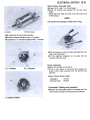
Removal
.Remove
.Remove
the pickup coil cover.
the mounting
bolts and take off the camshaft
chain tensioner.
A. Taper Part (Stopper)
B.
Push
Rod
.Compressing
the spring against the push rod head,
insert a thin wire through the hole in the push rod to
keep the spring in place.
A.
Camshaft
Chain
B. Mounting
Bolts
.Pull
Tensioner
c.
Lock
out the rod from the cam chain guide
Bolt
(rear side)
A. Wire
B. O-ring
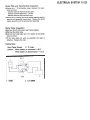
.Apply
.Install
grease to the O-ring.
the top end of a extension rod into a hole of the
chain guide.
! nsta!!ation
.Compressing
the push rod. into the tensioner body and
lock it.
O Remove the lock bolt on the side of the tensioner body.
OWhile pushing the taper part of the stopper, push the
rod.
A.
Extension
Rod
B.
Chain
Guide
.Install the tensioner body on the engine.
.Apply a non-permanent locking agent to the mounting
bolts and tighten them to the specified torque (see
Exploded View).
.Pull the wire out and tighten the lock bolt.
.Install the pickup coil cover.
4-10
ENGINE
TOP END
OApply silicone sealant to the crankcase parting line and
grommet (see 4-12).
OApplya non-permanent
(see 4-12).
Camshaft
locking agent to only one bolt
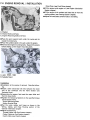
Camshaft Removal
.Remove the following.
Lower Fairings (see Frame chapter)
Pickup Coil Cover
Damper Rubber (from Rear Cam Chain Guide)
.Remove the following.
Carburetor (see Fuel System chapter)
Cylinder Head Cover (this chapter)
Spark Plug Retainer
Camshaft Chain Tensioner (this chapter)
NOTE
OBefore
removing
crankshaft
the
at # 1, 4 piston
chain
tensioner,
position
the
TDC.
1. TDC Mark
3. Front
2. Timing Mark (Crankcase Parting Line)
.Remove
the camshaft cap bolts and take off
camshaft caps, camshafts and upper chain guide.
A.
Camshaft
B.
Camshafts
Caps
the
C. Upper Chain Guide
.Stuff a clean cloth into the chain tunnel to keep any
parts from falling into the crankcase.
ENGINE
TOP END
4-11
.Pull the tension side (exhaust side) of the chain taut to
install the chain.
OThe timing marks must be aligned with the cylinder
head upper surface and positioned respectively as
shown, after the camshaft chain slack is taken up by the
tensioner.
Camshaft Installation
.Installation
is the reverse of removal.
Note the follow-
ing.
.Apply engine oil to all cam parts. If the camshaft(s)
and/or cylinder head are replaced with new ones, apply
a thin coat of molybdenum disulfide grease to the new
cam part surfaces.
NOTE
0 The exhaust camshaft has an EX mark and the inlet
camshaft has an IN mark. Be careful not to mix up these
shafts.
.The
camshaft
cap locations
caps in the positions
are numbered.
Install
the
as shown.
CD
Itr=
1.
EX
Mark
2.
IN
Mark
.Position
the crankshaft at TDC for the #1 and #4
pistons, engage the cam chain with the camshaft
sprockets as shown.
1 .Camshaft
2. Upper
.Tighten
3.
Cap
Chain
Location
Number
Guide
the camshaft cap bolts to the specified torque
(see Exploded View).
.Install the camshaft chain tensioner.
.Install the pickup coil cover, noting the following.
OApply silicone sealant to the following.
Crankcase Parting Line
Grommet
4-12
ENGINE
TOP END
NOTE
0 Do not turn the camshaft when the plastigage
between the journal and camshaft cap.
*If
any clearance
diameter
exceeds
of each camshaft
the service
journal
limit,
with
measure
is
the
a micrometer.
Camshaft. Camshaft Cap Clearance
#1. #4 Journals
Standard:
Service limit:
#2. #3 Journals
Standard:
Service limit:
A. Apply silicone sealant.
.Apply
a non-permanent
locking
agent
to the following
bolt only.
0.028 -0.071
0.16 mm
mm
0.078- 0.121 mm
0.21 mm
*If
the camshaft journal diameter is less than the service
limit (see Specifications), replace the camshaft with a
new one and measure the clearance again.
* If the clearance still remains out of the limit, replace the
cylinder head unit.
Camshaft
Chain Wear
.Hold the chain taut with a force of about 5 kg in some
manner, and measure a 20-link length. Since the chain
may wear unevenly, take measurement at several places.
* If any measurement exceeds the service limit, replace the
chain.
Camshaft
A. Apply
a non-permanent
locking
Chain 20-Link
Standard:
Service Limit:
agent.
Chain length
Camshaft,
.Measure
camshaft
Camshaft
Cap
each clearance
cap using
Wear
between
plastigage
the camshaft
and the
(press gauge).
NOTE
0 Tighten the camshaft cap bolts to the specified torque
(see Exploded View).
A.
Plastigage
Width
length
127.0 -127.4
128.9 mm
Measurement
mm
ENGINE
I
Rocker Arm, Rocker Shaft
TOP END
4-13
~
Rocker Arm and Rocker Shaft Removal
.Remove the camshafts(this chapter).
I
-L&-
<D~.;~
NOTE
0 Mark the rocker arms so they may be put back in the
same position.
.Remove the rocker shaft plug and rocker shaft. and take
off the rocker arms.
-
1. Springs (conical)
2. Springs
.Tighten
the following
to the specified
torque
Exploded View).
Upper Chain Guide Bolts
Camshaft Cap Bolts
Rocker Shaft Plug
Rocker
.1 nspect
A.
Plug
B.
Rocker
Rocker
c.
*If
Shaft
Arms
Arm
Installation
.Blow
Rocker
and
Rocker
Shaft
Notes
the rocker arm oil passage
air and apply
oil to the rocker
clean with
compressed
arm bore before
installa-
tion.
1.
Rocker
Arm
2. Oil
Pressure
.Apply engine oil to the rocker shaft, and insert the shaft
running it through the cylinder head, the rocker arms
and springs.
.Install the retainer spring on each rocker arm as shown.
Arm
and
Rocker
Shaft
the rocker arms and rocker
they are badly worn,
replace
Inspection
shafts.
them.
Note
(see
4-14
ENGINE
Cylinder
TOP END
Removal
.Drain coolant (see Cooling System chapter)
.Remove the following.
Radiator (see Cooling System chapter)
Muffler
Camshafts (see this chapter)
Oil Hose (Cylinder Head)
Engine Mounting Bracket Bolts, Nuts (Cylinder Head)
.Remove the cylinder head bolts and take off the cylinder
head.
Head
Cylinder CompressionMeasurement
NOTE
0 Use the battery which is fully charged.
.Warm up the engine thoroughly.
.Remove the following.
Fuel Tank (see Fuel System chapter)
Surge Tank (see Fuel System chapter)
Spark Plugs
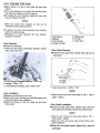
.Attach
the compression gauge and adapter
tools) firmly into the spark plug hole.
(special
I nstal/ation
.Installation
is the reverse of removal.
Exploded View).
Camshaft Chain Guide Bolt (rear side)
Cylinder Head Bolts
Camshaft Cap Bolts
Upper Chain Guide Bolts
Oil Hose Mounting Bolts
Engine Mounting Bolts
.Tighten the cylinder head bolts following
A. Compression Gauge: 57001-221
B. Adapter: 57001 -1317
sequence.
.Hold the throttle wide open and crank the engine with
the starter.
.When the gauge stops rising, stop cranking and read the
gauge.
Cylinder
Compression
Usable Range:
686 -1
079 kPa @330 r/min
(7.0 -11.0
kg/cm2. 99 -156
Note the follow-
ing.
.Install the new cylinder head gasket with a new one.
.When the engine is mounted on the frame, install the
chain guide (rear side) into the cylinder head, and
tighten the mounting bolt to the specified torque (see
Exploded View) .
.Beforehand
install the chain guide into the cylinder
head.
.Tighten the following bolts to the specified torque (see
(rpm)
psi)
*If
cylinder compression is higher than the specified
range, check the following.
O Carbon build-up on the cylinder head combustion
chamber
OCarbon build-up on the piston head
* If cylinder compression is lower than the specified
range, check the following.
O Valve not seating properly
O Piston/cylinder clearance excessive
O Gas leakage around the cylinder head gasket
O Valve clearance too small
O Piston ring/piston ring groove clearance
.Install
the chain guide
(front
side)
the tightening
ENGINE
TOP END
4-15
Valves
Valve Clearance Adjustment
NOTE
0 Valve clearance must be checked and adjusted when
the engine is cold (at room temperature).
.Remove the following.
Cylinder Head Cover
Spark Plug Retainer
.Using a thickness gauge, measure the valve clearance
between the rocker arm and the cam.
OWhen positioning
#4 piston TDC at the end of
the compression
stroke:
inlet valve clearance of #2 and #4 cylinders
exhaust valve clearance of #3 and #4 cylinders (see
Camshaft Removal)
Measuring
Valves
;f!;Jnmyi;
1. Exhaust Valves
2. Inlet Valves
3.
Cylinder
Numbers
0 When positioning #1 piston TDC at the end of
the compression stroke:
inlet valve clearance of #1 and #3 cylinders
exhaust valve clearanceof #1 and #2 cylinders
Measuring Valves ttl~f
1.
Exhaust
2.
Inlet
3.
Valves
Cylinder
Numbers
Valves
Valve Clearance
Standard:
(between
Cam and Rocker Arm)
Inlet:
0.12 -0.17
mm
Exhaust:
0.16 -0.21
mm
4-16
ENGINE
TOP END
.Apply
engine oil to the O-ring,
retainer.
install the spark plug
*If
the valve clearance is not within the specified range,
first record the clearance, and then adjust it.
.To change the valve clearance, replace the shim with
one of a different thickness.
NOTE
0 Mark and record shim locations
reinstalled in their original positions.
so they
can be
.To select a new shim which brings the valve clearance
within the specified range.
0 Remeasure any valve clearance that was adjusted.
Readjust if necessary.
Valve
tool),
5. Spring Seat
6. Oil Seal
7. Valve Stem
Removal
.Perform
O Using
1 .Split Keeper
2. Retainer
3. Valve Spring
4. Closed Coil End
the following.
the
valve
remove
spring
compressor
assembly
(special
the valve.
Valve Guide Removal
.Using the valve guide arbor (special tool), tap out the
valve guide.
"'--'
(D;
"
~
0
A. Valve Spring Compressor Assembly: 57001-241
B. Adapter: 57001 -1272
C. Valve Spring Compressor Joint: 57001 -1271
1. Valve Guide Arbor:
57001-1273
NOTE
Valve Installation
.Replace the oil seal with a new one.
.Applya
thin coat of molybdenum disulfid~ grease to the
valve stem before valve installation.
.Install
the springs so that the closed coil end faces
downwards.
CHeat the area around the valve guide to 120-
150 oC
(248 -302°F).
Valve Guide Installation
.Using
the valve guide arbor (special tool), drive the
valve guide until its flange touches the cylinder head.
NOTE
OHeat the area around the valve guide hole to 120 1500C (248 -302°F).
OApply oil to the valve guide outer surface before valve
guide installation.
.Using the valve guide reamer (special tool), ream the
valve guide.
ENGINE
1. Valve Guide
Reamer:
TOP
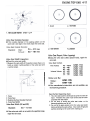
1 .Good
2.
3. Too narrow
4. Uneven
Too
END
4-17
wide
57001-1274
Valve Seat Outside Diameter
.If the outside diameter of the seating pattern on the
valve seat is too large or too small, repair the valve seat.
Valve Seat Outside
Standard:
Diameter
Inlet :
Exhaust
:
21.5 ~ 21.7 mm
18.5 ~ 18.7 mm
Valve Seat Repair
{Valve
Lapping)
.Using
the valve seat cutters (special
Valve Seat Width Inspection
.Check the valve seat width.
O Measure the seat width of the portion where there is no
build-up carbon (white portion) of the valve seat with
tools),
repair
the
valve seat.
Valve
Seat
Inlet
a vernier caliper.
Cutters
Valves:
45° -Q>24.5
32° -Q>25
60° -Q>30
Exhaust
Valves:
45° -Q>22
32° -Q>22
60° -Q>30
57001-1113
57001-1118
57001-1123
57001-1205
57001-1206
57001-1123
Holder and Bar
57001-1275
57001-1128
Holder:
Bar:
*If
the manufacture's
the following
1.Valve
2. Valve Seat
3. Seating
Surface
Outside
Diameter
4. Valve Seat Width
Valve Seat Width (IN and EX)
Standard:
0.5 --1.0 mm
* If the valve seat width is not within the specified range,
repair the valve seat.
instructions
are not available, use
procedure.
Seat Cutter Operating
Care:
1 .This valve seat cutter is developed to grind the valve for
repair. Therefore the cutter must not be used for other
purposes than seat repair.
2. Do not drop or shock the valve seat cutter, or the
diamond particles may falloff.
3. Do not fail to apply engine oil to the valve seat cutter
before grinding the seat surface. Also wash off ground
particles sticking to the cutter with washing oil.
4-18
ENGINE
TOP
END
NOTE
ODo not use a wire brush to remove the metal particles
from the cutter. It will take off the diamond particles.
4. Setting the valve seat cutter holder in position, operate
the cutter in one hand. Do not apply too much force
to the diamond portion.
NOTE
0 Prior to grinding, apply engine oil to the cutter and
during the operation, wash off any ground particles
sticking to the cutter with washing oil.
5. After use, wash it with washing oil and apply thin layer
of engine oil before storing.
1. Outer
Diameter
2. Angle
of Cutter
of Cutter
3. Cutter
Operating
Procedures:
.Clean the seat area carefully.
.Coat the seat with machinist's dye.
.Fit a 45° cutter into the holder and slide it into the valve
guide.
.Press down lightly on the handle and turn it right or left.
Grind the seating surface only until it is smooth.
1.
Cutter
2.
Cutter
Marks
3. Bar
Holder
Stamped
on the
The marks stamped
Cutter:
on the back of the cutter
represent
the following.
45°
Cutter
24.5<1>
Outer diameter
.Measure
the outside diameter of the seating surface
with a vernier caliper.
*If the outside diameter of the seating surface is too
small, repeat the 45° grind until the diameter is within
the specified range.
*If
angle
of cutter
*If
the outside diameter of the seating surface is too large,
make the 32° grind described below.
the outside diameter of the seating surface is within
the specified range, measure the seat width as described
below.
.Grind the seat at a 32° angle until the seat O.D. is within
the specified range.
OTo make the 32° grind, fit a 32° cutter into the holder,
and slide it into the valve guide.
OTurn the holder one turn at a time while pressing down
very lightly. Check the seat after each turn.
ENGINE
Valve
TOP END
4-19
Lapping
::70
l'"-'
@
-r-~
-""~ccccc..iccc.-c
~~
@,
OAfter making the 32° grind, return to the seat O.D.
measurement step above.
.To measure the seat width, use a vernier caliper to
measure the width of the 45° angle portion of the seat
at several places around the seat.
*If the seat width is too narrow, repeat the 45° grind until
the seat O.D. measurement step above.
* If the seat width is too wide, make the 60° grind
described below.
.Grind the seat at a 60° angle until the seat width
is
within the specified range.
OTo make the 60° grind, fit 60° cutter into the holder, and
slide it into the valve guide.
OTurn the holder, while pressing down lightly.
O After making the 60° grind, return to the seat width
measurement step above.
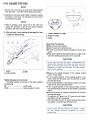
.Lap the valve to the seat, once the seat width and O.D.
are within the ranges specified above.
O Put a little coarse grinding compound on the face of the
valve in a number of places around the valve head.
O Spin the valve against the seat until the grinding
compound produces a smooth, matched surface on
3. Valve
1 .Lapper
2. Valve
Measure
Seat
Valve-to-Guide
Clearance
(Wobble
Method)
If a small bore gauge is not available, inspect the valve
guide wear by measuring the valve to valve guide
clearance with the wobble method as indicated below.
.Insert a new valve into the guide and set a dial gauge
against the stem perpendicular to it as close as possible
to the cylinder head mating surface.Move the stem back and forth to measure valve/valve
guide clearance.
.Repeat the measurement in a direction at a right angle
*If
to the first.
the reading exceeds the service limit,
replace the
guide.
NOTE
both the seat and the valve.
0 Repeat the process with a fine grinding compound.
.The seating area should be marked about in the middle
0 The reading is not actual valve/valve guide clearance
because the measuring point is above the guide.
of the valve face.
the seat area is not in the right place on the valve,
check to be sure the valve is the correct part. If it is, it
may have been refaced too much; replace it.
.Be
sure to remove all grinding compound
before
Valve/Valve Guide Clearance (Wobble Method)
*If
assembly.
.When the engine is assembled, be sure to adjust the
valve clearance (see Valve Clearance Adjustment).
Inlet
Exhaust
Standard
0.031 -0.140 mm
0.085 -0.180 mm
Service Limit
0.34 mm
0.41 mm
4-20
ENGINE
TOP END
Cylinder,
Pistons
Cylinder
Removal
.Remove
the following.
Cylinder
Head
Camshaft
Water
(see Cylinder
Chain
Guide
Head Removal)
(exhaust
side)
Pipe
.Remove
the cylinder.
Cylinder Installation
.Install the new cylinder gasket.
.Apply engine oil to the cylinder bore.
.Using the piston base (special tools), install the cylinder
block.
1. New
2. Valve
Valve
3. Move the Valve.
Guide
A. Piston
.Install
Base:
the cylinder
as shown.
1.
Chain
57001
Guide
-147
and the chain
guide
(exhaust
side)
ENGINE
TOP END
4-21
Piston Removal
.Remove the cylinder (see this chapter).
.Place a clean cloth under the pistons and remove the
piston pin snap rings from the outside of each piston.
.Using
the piston pin puller assembly (special tool),
remove the piston pins.
@--
t}
@@
1.TopRing
2. Second Ring
3. Oil Ring Steel Rails
Piston
.The
Installation
top and second
rings must
marks on the rings facing
be installed
with
of
the
shown
.The
Ring
2.
Second
Ring
Expander
Wear
the
two
cylinder
inside
and a front-to
positions
(total
back
of
diameter
measurement
four
arrow on the piston head must point toward the
about 30 -40°
of angle from the opening of the top
Cylinder
Inside Diameter:
Standard:
Service limit:
57.000 -57.012
57.10 mm
taking
mm
a
at each
measurements)
below.
Ring
front of the engine.
.The piston ring openings must be positioned as shown
below. The openings of the oil ring steel rails must be
rinc.
Arrow
the R
side-to-side
Top
Oil
5.
up.
Cylinder
.Measure
1.
4.
4-22
ENGINE
TOP
END
Piston Wear
.Measure the piston outside diameter 5 mm up from the
bottom of the piston at a right angle to the direction of
the piston pin.
Piston Ring End Gap
.Place the piston ring inside the cylinder, using the
piston to locate the ring squarely in place. Set it close
to the bottom of the cylinder, where cylinder wear is
low.
.Measure the gap between the ends of the ring with a
thickness gauge.
Piston Outside Diameter
Standard:
Service Limit:
56.942 -56.957
56.79 mm
mm
Piston Ring End Gap
Piston Diameter Measurement
Standard
0.20 -0.40
mm
0.35 -0.50
mm
Top
Second
YJ
Service limit
O.7mm
O.8mm
I
I
(LCD
.,i
I.
1. Piston
2. 5mm
Outside
up from
Diameter
bottom
--@
Piston Ring, Piston Ring Groove Wear
.Check for uneven groove wear by inspecting
seats.
the ring
*The rings should fit perfectly parallel to the groove
surfaces. If not, the piston must be replaced.
.With the piston rings in their grooves, make several
measurements with a thickness gauge to determine
piston ring/groove clearance.
Piston Ring/Groove Clearance
Standard:
Service Limit:
1. Thickness
Gauge
0.03 -0.07
0.17 mm
mm
1. Gap
2.
Piston
Ring
ENGINE
TOP END
4-23
Carburetor Holders
M uffler
Removal
Removal
.Remove the following.
Lower Fairing
Radiator {Do not remove the hoses and not drain
.Remove
the
following.
Clamps
Allen
Bolts
.Remove
A.
the
Carburetor
inlet
pipes.
Holders
coolant.)
.Remove the nuts and take off the exhaust pipe holders.
B. Inlet Pipes
B. Holder
A. Nuts
.Take
off the holders
from the inlet pipes.
.Remove
the muffler mounting
bolt and nut (rear step
bracket).
.Remove the muffler.
I nstal/ation
.Install the carburetor holder so that the pipe is upward.
.Install the holder clamps as shown being careful of the
screw position and the screw head direction.
I nstal!ation
.Installation
.Replace
1 .Holder
2. Screw
Clamp
3. Screw Head
4. Stopper
is the reverse of removal.
the exhaust
gaskets.
CLUTCH
T able
Special
Specifications
Sealant
Exploded
Clutch.
Tools
View
,
of
Contents
,
,
..5- 2
..5- 3
..5- 3
..5- 3
..5- .4
Clutch
Clutch
Adjustment
Check
,
..5. .4
..5- .4
Clutch
Release
Clutch
Clutch
Clutch
Friction
Cover
Installation
Removal
Plate
Lever
Removal
Installation
..5. .5
Notes...
..5. .5
Removal
Installation
Wear,
Notes Damage
Note
Inspection
,
,
..
..5. .5
..5. .5
..5. -6
..5. -6
..5. -7
Clutch
Friction
Spring
or
Steel
Free
Plate
Length
Warp
Measurement
Inspection
..5 -8
..5 -8
Clutch
Clutch
Housing
Hub
Spline
Finger
Inspection
Inspection
..5 -8
..5 -8
5-1
5-2
CLUTCH
T1: 12 N-m (1.2 kg-m. 8.5 ft-Ib)
T2: 9.8 N-m (1.0 kg-m. 7.0 ft-Ib)
T3: 130 N-m (13.5 kg-m. 98 ft-Ib)
L : Apply a non-permanent
locking agent to the threads.
M: Apply a thin coat of a molybdenum disulfide grease.
55: Apply silicone sealant to the threads.
,
n
@
see
5-5
CLUTCH
Specifications
Special Tools
Sealant
5-3
5-4
ClUTCH
Clutch
Due to the fiction plate wear and clutch cable stretch
over a long period of use, the clutch must be adjusted in
accordance with the Periodic Maintenance Chart.
Clutch
.Pull
Adjustment
the clutch
.Measure
the
A. Fairing Mounting
B. Fairing Mounting
Check
lever just enough
gap
between
to take up the free play.
the
lever
and
the
lever
Lever Free Play 2 -3
mm
bracket.
A. Adjuster
C. Clutch
Screws
Bolts
.Loosen the lower cable adjusting
cover as far as they will go.
A.
Adjusting
B. Locknut
B.
Bracket
*If
.Loosen
the gap is too wide, the clutch may not release fully.
If the gap is too narrow, the clutch may not engage fully.
In either case, adjust the clutch.
nuts at the clutch
C. Pull Outer Cable.
Nuts
the knurled locknut at the clutch lever.
.Turn the adjuster so that 5 -6
visible.
mm of threads are
Clutch Adjustment
.Loosen the knurled locknut at the clutch lever.
.Turn the adjuster so that the clutch lever will have 2 3 mm of play.
.Tighten the locknut.
*If it cannot be done, use the adjusting nuts at the lower
end of the cable.
.Remove the fairings.
A. Adjuster
C.
5
-6
mm
B. Locknut
.Pull
the clutch
adjusting
cable
nuts against
tight
and tighten
the bracket.
the
lower
cable
CLUTCH
.Turn the adjuster at the clutch lever until the free play is
correct. At this time, check that the clutch release lever
to clutch cable angle is 80 -gOD.
A. Release
B. 80
Lever
C.
Clutch
5-5
Clutch Cover Removal
.Drain the engine oil (see Engine Oil Change in Engine
Lubrication System chapter).
.Remove the lower fairing (see Lower Fairing Removal
in Frame chapter).
.Remove the inner cover.
.Remove
the clutch cable lower and from the clutch
cover.
.Remove the clutch cover bolts and take off the cover.
Cable
-90°
Clutch
.Replace
* If the clutch cannot be adjusted by this method, inspect
the clutch parts.
.Tighten the knurled locknut at the clutch lever.
.Apply
Cover
Installation
the clutch
silicone
Note
cover gasket
with
sealant to the mating
a new one.
surface
as shown.
NOTE
OBe sure that the outer cable end at the clutch lever is
fully seated in the adjuster at the clutch lever, or it could
slip into place later, creating enough cable play to
prevent clutch disengagement.
.After the adjustment is made, start the engine and check
that the clutch does not slip and that it releases properly.
Clutch ReleaseLever Removal
A. Silicone Sealant (Kawasaki Bond:
.Clamp
the pick-up
56019-120)
coil wire as shown.
.Place a suitable container under the clutch cover.
.Remove the clutch cover (see this chapter).
.Turn the release lever counter clockwise, and then pull
out the release lever with its shaft.
Clutch Release Lever Installation
Notes
.Visually
inspect the oil seal, and replace it if necessary.
.Install
the release lever, and turn it clockwise until it
stops.
A. Pick-up Coil Lead
.Apply a non-permanent
bolts and screw.
B. Clamp
locking agent tot he following
5-6
CLUTCH
A. Cover Bolt
B. Holder: 57001 -1243
A. Wrench
.Remove
the thrust washer, clutch hub, clutch cam,
washer, clutch housing, needle bearing, collar, and
spacer.
Clutch
Installation
.Clutch
attention
.Tighten
the clutch
(see Exploded
cover
bolts
to the specified
torque
View).
Clutch Removal
.Remove the clutch cover.
.Remove the clutch spring bolts, retainers, and springs;
then take off then clutch spring plate with the bearing
and pusher.
A.
Clutch
B. Retainer
Spring
Bolt
D. Pusher
E. Clutch Spring Plate
C. Bearing
.Remove the friction plates and steel plates as a set.
.Remove the clutch hub nut. When loosening the hub
nut, use the clutch holder (special tool) to keep the
clutch hub from turning as shown.
installation
Notes
is the
to the following
reverse
items.
of
removal.
Pay
CLUTCH
0 When
install the spring
5- 7
plate. align the marks on the hub
and the plate.
9.
10.
11.
12.
13.
14.
15.
16.
1 .Spacer
2. Needle
Bearing
3. Collar
4. Clutch
Housing
5. Washer
6. Clutch
Hub
7. Clutch
Cam
8. Friction
Plate
Steel Plate
Washer
Hub Nut
Pusher
Bearing
Spring Plate
Clutch Spring
Retainer
O Install the spacer with the chamfered side facing
inwards.
0 Install the clutch cam on the clutch hub.
0 Discard the used hub nut, and install a new nut.
0 Install the clutch holder (special tool: 57001 -1243) to
keep the clutch hub from turning and tighten the clutch
hub nut to the specified torque (see Exploded View).
0 Install the friction plates and steel plates, starting with a
friction plate and alternating them.
0 Install the last friction plate fitting the tangs in the
groove on the housing as shown.
1 .Last
Friction
A. Marks
O Tighten the clutch spring bolts to the specified torque
(see Exploded View).
.
Friction Plate Wear, Damage Inspection
.Visually inspect the friction plates to see if they show
any signs of seizure, overheating, or uneven wear.
* If any plates show signs of damage, replace the friction
plates and steel plates as a set.
.Measure
the thickness of the friction plates at several
*If
points (see Specifications).
any of the measurements is less than the service limit,
replace the friction plate.
Plate
OApply molybdenum
and ball bearing.
disulfide grease to the pusher end
Friction Plate Thickness
Standard:
Service Limit:
2.7 -2.9
2.5 mm
mm
5-8
ClUTCH
Friction
or Steel Plate Warp Inspection
.Place each friction plate or steel plate on a surface plate,
and measure the gap between the surface plate and
each friction plate or steel plate. The gap is the amount
of friction or steel plate warp.
*If
any plate is warped over the service limit, replace it
with a new one.
Clutch Housing
Finger Inspection
.Visually inspect the fingers of the clutch housing where
the tang of the friction plates hit them.
* If they are badly worn or if there are grooves cut where
the tang hit, replace the housing.
Also, replace the
friction plates if their tangs are damaged.
A. Clutch
1 .Friction
or Steel
Plate
2.
Thickness
Housing
Finger
B. Friction
Plate
Tang
Gauge
Friction and Steel Plate Warp
Standard:
Service Limit:
less than 0.2 mm
0.3mm
Clutch Hub Spline Inspection
.Visually inspect where the teeth on the steel plates wear
against the splines of the clutch hub.
* If there are notches worn into the splines, replace the
clutch hub. Also, replace the steel plates if their teeth
are damage.
Clutch Spring Free Length Measurement
.S~nce the spring becomes shorter as it weakens, check
its free length to determine its condition.
* If any of the springs is shorter than the service limit, it
must be replaced.
A. Clutch
A.
Clutch
Spring
Clutch Spring Free Length
Standard:
Service Limit:
33.6 mm
32.6 mm
Hub
Spline
Relief
Oil
Oil
Removal
Installation
Installation
Pump
Hose
Filter
Filter
Pump
Chart
,
Measurement
Oil
Change
Oil
Measurement
Inspection
Change
Flow
and
Oil
View
Tools
Oil
Oil
Pressure
Level
Filter
Valve,
Pressure
Cooler
Pan
Installation
Removal
Oil
Removal
Removal
Installation
Oil
Engine
Installation
Removal
Oil
Oil
Oil
Exploded
Engine
Special
Specifications
Engine
Sealant
Oil
ENGINE
Table
LUBRICATION
,
,
,
,
SYSTEM
of Contents
6-2
6-4
6-6
6-6
6-6
6- 7
6- 7
6- 7
6- 7
6-8
6-8
6-8
6-9
6-9
6-9
6-9
6-9
6-10
6-9
6-10
,
6-10
6-10
,
,
6-10
6-10
6-11
6-11
6-1
6-2
ENGINE
LUBRICATION
SYSTEM
Exploded View
@
>
~~~
~
\
<2'-
~
@
'@
T1: 1.5 N-m (0.15 kg-m.13 in-Ib)
T2: 4.4 N-m (0.45 kg-m. 39 in-Ib)
T3: 9.8 N-m (1.0 kg-m. 7.0 ft-Ib)
T4: 12 N-m (1.2 kg-m. 8.5 ft-Ib)
T5: 15 N-m (1.5 kg-m. 11.0 ft-Ib)
T6: 17 N-m (1.75 kg-m. 12.5 ft-Ib)
T7: 20 N-m (2.0 kg-m. 14.5 ft-Ib)
T8: 29 N-m (3.0 kg-m. 22 ft-Ib)
L : Apply a non-permanent
locking agent to the
threads.
SS: Apply silicone sealant to the threads.
6-4
ENGINE
LUBRICATION
Engine Oil Flow Chart
@-
SYSTEM
ENGINE
1.
2.
3.
4.
5.
6.
7.
8.
9.
10.
11.
12.
13.
14.
15.
16.
17.
18.
19.
20.
21.
22.
23.
24.
25.
Oil Pump Filter
Oil Pump
Oil Filter
Oil Passage
Oil Pressure Switch
Releif Valve
Oil Hose
Camshaft Bracket
Camshaft
Rocker Arm
Oil Return Passage
Oil Pipe (to Mission)
Oil Pipe (to Output Shaft)
Output Shaft
Drive Shaft
Crankshaft
Water Pump
Oil Pan
Oil Drain Plug
Oil Return Hose
Breather Plate
Breather Hose
Oil Cooler
Oil Cooler Hose
Bypass Hole
LUBRICATION
SYSTEM
6-5
6-6
ENGINE
LUBRICATION
SYSTEM
Specifications
Special Tools
Oil Pressure Gauge,
Sealant
10 kg/cm2:
57001 -164
Kawasaki Bond (Silicone Sealant):
~~
Oil Pressure
Gauge
Adapter.
M18
x 1.5:
57001-1278
56019-120
ENGINE
Engine
LUBRICATION
SYSTEM
6-7
Engine Oil Change
.Support
the motorcycle perpendicular to the ground
after warming up the engine.
.Remove the engine drain plug to drain the oil.
Oil and Oil Filter
Oil Level Inspection
.Support the motorcycle perpendicular to the ground.
.Check that the engine oil level is between the upper and
lower levels in the gauge.
A.
Drain
Plug
B. Front
OThe oil in the filter can be drained by removing the filter
(see Oil Filter Change).
*Replace
the drain plug gasket with a new one if it is
damaged.
.Tighten
the drain plug to the specified
-
torque
(see
Exploded View).
.Pour in the specified type and amount of oil.
Engine Oil
Grade:
SE or SF class
Viscosity: SAE 10W-40
Amount: 3.0 l (filter is removed)
2.8 l (filter is not removed)
~
1. Upper
Level
2. Lower
Level
3.Oil Filler Opening Plug
NOTE
OSituate the motorcycle so that it is perpendicular to the
ground.
Olf the motorcycle has just been used, wait several
minutes for all the oil to drain down.
O If the oil hasjust been changed, start the engine and run
it for severalminutes at idle speed. This fills the oil filter
with oil. Stop the engine, then wait several minutes
until the oil settles.
Oil Filter Change
.Remove the lower fairing.
.Drain the engine oil (see this chapter).
.Remove the oil filter with the oil filter wrench.
A.
Oil
Filter
.Replace the filter with a new one.
.When installing the oil filter, be careful of the following.
OApply oil to the gasket before installation.
6-8
ENGINE
LUBRICATION
SYSTEM
O Tighten the filter with the oil filter wrench to the
specified torque (see Exploded View) or tighten it with
hands about * turns after gasket contacts the mounting
surface of engine.
O Pour in the specified type and amount of oil.
Oil Pan
'Removal
.Set the motorcycle on its side stand.
.Remove the following.
Lower Fairings (see Frame chapter)
Muffler (see Engine Top End)
Engine Oil (Drain, see this chapter)
Oil Pressure Switch Lead
Oil Pressure Switch (as necessary)
Oil Pipes
A. Front
B. Switch Lead
.Remove
I nstal!ation
.Installation
c. Oil PressureSwitch
the oil pan bolts and take off the oil pan.
is the reverse of removal.
Note the follow-
ing.
.Apply silicone sealant to the threads of the oil pressure
switch and tighten it to the specified torque (see
Exploded View).
.Replace the gasket with a new one.
.Replace the O-rings with new ones if they are damaged.
.Tighten the oil pan bolts to the specified torque (see
Exploded View).
ENGINE
LUBRICATION
Relief Valve, Oil Pump Filter
Oil Pump
Removal
.Remove the oil pan.
.Unscrew the oil pressure relief valve from the engine.
.Pullout
the oil pump filter and the oil pipe.
Removal
.Remove the following.
Clutch (see Clutch chapter)
A. Relief Valve
B. Oil Pump Filter
c.
Unround
Portion
.Remove
is the reverse of removal.
6-9
Circlip
Oil Pump Gear
Oil Pump Cover
A. Pump Cover
I nstal/ation
.Installation
SYSTEM
B. Pump
Cover Screw
the oil pump shaft and pump rotor.
Note the follow-
ing.
OApplya non-permanent locking agent to the thread of
the releif valve and tighten it to the specified torque (see
Exploded View).
O Replace the oil pipe O-ring if it is damaged.
OWhen installing the oil pump filter, note the position of
its unround portion.
A.
Pump
Rotor
Installation
.Installation
B. Pump Shaft
is the reverse of removal.
Note the follow-
ing.
.When installing the oil pump, note the position of the
water pump shaft slot and turn the oil pump shaft so
that the projection fits into the slot.
.Tighten the oil pump cover screw to the specified torque
(see the Exploded view).
.Replace the pump gear circlip with a new one.
6-10
ENGINE
LUBRICATION
SYSTEM
Oil Hose
Oil Cooler
Removal
.Drain the engine oil.
.Remove the lower fairing (see Frame chapter).
.Remove the Allen bolts from the cylinder head and the
crankcase.
.Take out the oil hose.
Removal
.Remove the following.
Engine Oil (Drain, see this chapter)
Lower Fairings (see Frame chapter)
Muffler (see Engine Top chapter)
Oil Cooler Pipe Fitting Bolts
Oil Cooler Mounting Bolts
A.
Oil
Hose
B. Allen Bolt
A.
Fitting
.Remove
! nsta!!ation
.Installation
is the reverse of removal.
.Replace the O-rings with new ones if they are damaged.
.Tighten
the Allen bolts to the specified torque (see
Exploded View).
Installation
.Installation
ing.
.Replace
.Tighten
B. Moun,ting
Bolts
Bolts
the oil cooler.
is the reverse of removal.
Note the follow-
the O-rings with new ones.
the oil cooler pipe fitting bolts to the specified
torque (see Exploded View).
Oil Pressure Measurement
Oil Pressure Measurement
NOTE
0 Measure the oil pressure after the engine is warmed up.
.Remove the following.
Right Lower Fairing (see Frame chapter)
Oil Passage Plug
.Attach
the oil pressure gauge and adapter
tools) to the plug hole.
(special
A. Oil Pressure Gauge: 57001 -1 64
B. Adapter: 57001 -1278
Oil Pressure
Standard
*If
216 -275
kPa
(2.2 -2.8
kg/cm2. 31 -40
psi)
@4(XX) r/min (rpm). 90°C (194°F)
of oil temp.
the oil pressure is much lower than the standard,
check the oil pump, relief valve, and/or crankshaft
bearing insert wear immediately.
ENGINE
T able
Exploded
of
REMOVAL
/ INSTALLATION
Contents
View
Special
Engine
Removal
Installation
Removal/Installation
Tool
7,
,..,
:,
,
7 -4
7-1
7-2
ENGINE
REMOVAL
/ INSTALLATION
Exploded View
:.;@
T1: 30 N-m (3.1 kg-m. 22 ft-Ib)
T2: 36 N-m (3.7 kg-m. 27 ft-Ib)
Install a shim (thickness 0.5 mm) between the lower part
of the crankcase and the frame bracket.
ENGINE
REMOVAL
/ INSTALLATION
Special Tool
Engine Removal/Installation
Jack: 57001 -1238
Removal
.Remove the following.
Fairings (see Frame chapter)
Engine Oil ( Drain, see Engine Lubrication
~
7-3
System
chapter)
Coolant (Drain, see Cooling System chapter)
Fuel Tank (see Fuel System chapter)
Air Cleaner Housing (see Fuel System chapter)
Carburetors (see Fuel System chapter)
Baffle Plate
Oil Cooler and Oil Pipes (see Engine Lubrication
System chapter)
Radiator (see Cooling System chapter)
Muffler (see Engine Top End chapter)
Engine Sprocket (see Final Drive chapter)
.Disconnect
wiring from the engine and free them from
the clamps.
Clutch Cable
Spark Plug Caps
Pickup Coil Lead Connector
Battery Ground Lead Terminal
Starter Motor Lead Terminal
Water Temperature Sensor Lead Connector
Oil Pressure Switch Connector
Side Stand Switch Connector
Alternator Leads Connector
Neutral Switch Connector
A. Battery
Ground
B. Side Stand
C. Neutral
Lead Terminal
Switch
Switch
Connector
Connector
o If the crankshaft is to be removed after engine removal,
you may remove the following parts at this time.
Cylinder
Alternator
0 In case of the transmission, you may remove the clutch.
.Remove the engine mounting nuts and the bracket nuts
but do not remove the bolt as yet.
7-4
ENGINE
REMOVAL
/ INSTALLATION
.Fill
Drive Chain (see Final Drive chapter)
the engine with engine oil (see Engine Lubrication
System chapter).
.Fill the engine with coolant and bleed the air from the
cooling system (see Cooling System chapter).
.Adjust the carburetor synchronization and idling.
A. Bracket
B. Bracket Bolts and Nuts
C. Engine Mounting Bolts and Nuts
.Place the jack (special tool) under the swing arm to
steady the motorcycle.
.Place the suitable stand or the jack under the engine.
.Remove the engine mounting bolts. Support the engine
before sliding out the engine mounting bolts.
A. Jack: 57001-1238
B. Suitable Stand
I nsta//ation
.Installation
is the reverse of removal.
Note the follow-
ing.
.Install a shim (thickness 0.5 mm) between the lower
part of the crankcase and the frame bracket (see
Exploded View).
.Supporting
the engine, first insert the upper bolts. and
then the lower bolts.
.Tighten
the following fasteners to the specified torque
(see Exploded View).
Engine Mounting Bolts
Engine Bracket Bolts
.Run
the wires, cables, and hoses as shown in the
Wiring, Cables, and Hose Routing section of the
General Information chapter.
.Adjust the following.
Throttle Cables (see Fuel System chapter)
Choke Cable(see Fuel System chapter)
Clutch Cable (see Clutch chapter)
External
External
Transmission
Shift
Main
Removal
Installation
and
and
,.,
Wear
,
,
'
,
,
;
,
,
,
,
,
Rods
Splitting
Assembly
View
Tools
Crankcase
Crankcase
Exploded
Specifications
Special
Crankcase
Sealant
Crankshaft/Connecting
of
,
Insert/Crankpin
Bearing
End
Removal
Installation
Big
Rod
Rod
Rod
Removal
Installation
Crankshaft
Crankshaft
Connecting
Connecting
Connecting
Table
:
Wear
Removal
Installation
Removal
Installation
Removal
Installation
Bearing/journal
Clearance
Fork
Fork
Mechanism
Mechanism
Shaft
Shaft
Disassembly
Assembly
Disassembly
Assembly
Side
Shift
Shift
Drum
Drum
Drum
Drum
Pedal
Pedal
Shift
Shift
Shift
Crankshaft
Crankshaft
Shift
Shift
Transmission
Transmission
Transmission
Transmission
CRANKSHAFT
/ TRANSMISSION
Contents
...8-2
...8-4
...8-6
...8-6
...8-7
...8-7
...8-7
...8-9
...8-9
...8-9
.8-10
.8-10
.8-10
..8-12
..8-13
..8-14
..8-14
..8-14
..8-14
..8-14
..8-14
..8-15
..8-15
..8-15
..8-17
..8-17
..8-17
..8-17
8-1
8-2
CRANKSHAFT
Exploded
/ TRANSMISSION
View
,()
@--@
@4
~
~
:--.
()'
,
see
c/~~
8-7
~~
~
!
)@
1/'
e
@
~
IV
~
0 "
~
,~
see 8-8
@
CD
@@
~
X
~
~
Upper
,
Case
~
d
q
~C"
~
@6mm
I
SDID
I
8mm
@-,
-@
d
T1: 8.8 N-m (0.9 kg-m. 78 in-Ib)
T2: 9.8 N-m (1.0 kg-m. 7.0 ft-Ib)
T3: 12 N-m (1.2 kg-m. 8.5 ft-Ib)
T4: 15 N-m (1.5 kg-m. 11.0 ft-Ib)
T5: 20 N-m (2.0 kg-m. 14.5 ft-Ib)
T6: 25 N-m (2.6 kg-m. 19 ft-Ib)
T7: 27 N-m (2.8 kg-m. 20 ft-Ib)
G : Apply grease.
H : Apply high temperature grease.
lG: Apply liquid gasket -black
(Kawasaki Bond:
92104-1003) to the mating surface of the right
and left crankcase halves.
l : Apply a non-permanent
locking agent to the
threads.
55: Apply
silicone
sealant
(Kawasaki
Bond:
56019-120) to the gaskets and the threads.
M : Apply a thin coat of a molybdenum disulfide
grease.
~
8-4
CRANKSHAFT
/ TRANSMISSION
Specifications
Item
Standard
Crankshaft,
Connecting
Rods:
Connecting rod big end side clearance
Connecting rod big end bearing
insert/crankpin clearance
Crankpin diameter:
Marking
None
o
Connecting rod big end bore diameter:
Marking
None
0
Connecting rod big end bearing
insert thickness:
Blue
Black
Brown
0.130.031
29.984
29.98429.995
33.000
33.000
33.009
Service
0.38 mm
0.60
-0.059
mm
-30.000
mm
29.994 mm
-30.000
mm
-33.016
mm
-33.008
mm
-33.016
mm
1 .480 -1
1 .485 -1
1 .490 -1
Limit
mm
0.10mm
29.97 mm
.485 mm
.490 mm
.494 mm
Connecting rod big end bearing insert selection:
Con-Rod Big End
Bore Diameter
Crankpin Diameter
I
Marking
0
Crankshaft side clearance
Crankshaft runout
Crankshaft main bearing insert,
journal clearance
Crankshaft main journal diameter:
Marking
None
1
Crankcase main bearing bore diameter:
Marking
0
None
Crankshaft main bearing insert thick~ess
Brown
Black
BI11e
Bearing Insert
Size Color
92028-1494
Brown
0.05 -0.20
mm
0.02 mm or less
0.014
29.984
29.98429.993
33.000
33.000
33,009
-0.038
mm
-30.000
mm
29.992 mm
-30.000
mm
-33.016
mm
-33.008
mm
-33.016
mm
1 .491 -1
.495 mm
1 .495 -1
1 .499 -1
.499 mm
.503 mm
0.40
0.05
0.08
29.96
mm
mm
TIR
mm
mm
CRANKSHAFT
/ TRANSMISSION
*The bearing inserts for No.5 has no oil groove
I
Transmission:
Shift fork ear thickness
Gear shift fork groove
width
Shift fork guide pin diameter
Shift drum groove
width
4.9 -5.0 mm
5.05- 5.15 mm
5.9 -6.0 mm
6.05 -6.20 mm
4.8mm
5.3mm
5.8mm
6.3mm
8-5
8-6
CRANKSHAFT
/ TRANSMISSION
Special Tools
Sealant
Socket Wrench, Hex 8: 57001 -1268
Outside Circlip Pliers: 57001-144
~
Beari~g Driver Set: 57001 -1129
CRANKSHAFT
Crankcase
/ TRANSMISSION
.Apply
mountinga non-permanent
bolt (see Explodedlocking
View). agent
8-7
.to
the
plate
Crankcase Splitting
.Remove the engine (see Engine Removal/Installation
chapter) .
.Set the engine on a clean surface and hold the engine
steady while parts are being removed.
.Remove the following.
Cylinder Head (if the crankshaft is to be removed, see
Engine Top End chapter)
Cylinder, Piston (if the crankshaft is to be removed, see
Engine Top End chapter)
Starter Motor (see Electrical System chapter)
Crankcase Bolt (upper and lower)
.,f necessary, remove the following.
Clutch (see Clutch chapter)
External Shift Mechanism (see this chapter)
Timing Rotor (see this chapter)
Oil Pump (see Engine Lubrication System chapter)
Alternator Rotor (see Electrical System chapter)
Water Pump (see Cooling System chapter)
Oil Filter Mounting Bolt
Oil Pan
Oil Pump Filter
Oil Pipe
.Gently tap the crankcase half with a plastic mallet, and
separate the crankcase halves.
ss: Apply silicone sealant
L: Apply a non-permanent locking agent
1 .Breather Plate
2. Oil Return Hose
3. Oil Pipe
fi)
~@
~~
(C
~
,/
O
CD
~
J!JiiII;f;«
Crankcase Assembly
Q)
SS: Apply
L: Apply
1 .Left
breather plate.
silicone
locking
Oil Plug
Oil Plug
3. Neutral
Switch
4. Return
Spring
.Install
sealant
a non-permanent
2. Right
.With a high-flash point solvent, clean off the mating
surfaces of the crankcase halves and wipe dry.
.Using compressed air, blowout the oil passages in the
crankcase halves.
.Install the oil pipe.
.Apply
silicone sealant to the breather plate mating
surface on the upper crankcase and then install the
/
~f
Bolt
the set pins and rings.
agent
8-8
CRANKSHAFT
A. Set
Pin
B. Set
Rings
/ TRANSMISSION
c. Oil Passage
A. Oil Return Hose Clamp
.Apply engine oil to the transmission gears, ball bearings,
shift drum, and crankshaft main bearing inserts.
.Apply
liquid gasket -black
and silicone sealant as
shown in the figure below.
.Tighten
the crankcase mounting bolts following
tightening sequence to the specified torque
Exploded View).
O Following the tightening sequence, tighten the 8
bolts first to about one half of the specified torque,
finally to the specified torque.
O Tighten the 6 mm bolts to the specified torque.
Lower Crankcase
@
~
~
!:1'=F1R ~
fFC
~~ ~
@~
rlIO~
C1
: Liquid
~
92014-002)
: Silicone Sealant
Apply
Gasket
silicone
-Silver
( Kawasaki
sealant
upon
(Kawasaki
Bond:
liquid
Bond:
56019-120)
gasket.
.Install the crankshaft, shift drum and transmission.
.Set the grip of clamp backward at the crankcase.
D
18
)
a
~
A. <!>8 x L95
mm
B. <!>8 x L90
mm
:?>
0
c. <!>6x L40 mm
the
(see
mm
and
CRANKSHAFT
Upper
/ TRANSMISSION
8-9
Crankcase
Crankshaft/Connecting
Crankshaft
Rods
Removal
.Remove
the engine.
.Remove
the cylinder
head, cylinder
.Split
the crankcase
(see Crankcase
.Take
the crankshaft
out of the upper
and pistons.
Splitting).
crankcase.
Crankshaft Installation
.Apply high temperature grease to the output shaft oil
seal lips and press the oil seal in the crankcase until the
seal is even with the end of the hole.
.Install the collar.
1 .Oil seal is even with end of hole.
2. Collar
.Check the following.
O Shift drum is in the neutral position.
OThe #1 and 4 pistons are at TDC.
0 Drive shaft and output shaft turn freely.
O Neutral finder operates properly (while spinning
output shaft, gears can be shifted from 1 st to 2nd).
~
,
the
0.
Apply
.Apply
engine
oil,
engine oil to the crankshaft main bearing inserts.
8-10
CRANKSHAFT
Connecting
Rod
/ TRANSMISSION
Removal
.Remove
the crankshaft-
.Remove
the connecting
rods from the crankshaft.
NOTE
0 Mark and record the locations of the connecting rods
and their big end caps so that they can be reassembled
in their original positions.
1 .Big
End
Cap
2. Connecting
3.
Weight
Mark,
Alphabet
Rod
.Apply engine oil to the big end bearing inserts.
.Tighten
the big end cap nuts to the specified torque
(see Exploded View).
1. Main
Bearing
2. Connecting
Inserts
Rod
3. Big
End
4. Crankshaft
Cap
Connecting
Rod
Big
InsertlCrankpin
.Measure
Connecting Rod Installation
the
bearing
End
Bearing
Wear
insert/crankpin
clearance
with
a
plastigage.
A. Crankpin
B. Plastigage
NOTE
o Tighten the big end cap nuts to the specified torque
(see Exploded View).
ODo not move the connecting rod and crankshaft during
clearance measurement.
CRANKSHAFT
/ TRANSMISSION
8-11
Connecting Rod Big End Bearing
Insert/Crankpin Clearance
Standard:
Service limit:
0.031 -0.059
0.10 mm
mm
* If clearance is within the standard, no bearing replacement is required.
*If clearance is between 0.059 mm and the service limit
(0.10 mm), replace the bearing inserts with inserts
painted blue. Check insert/crankpin clearance with the
plastigage.
The clearance may exceed the standard
slightly, but it must not be less than the minimum in
order to avoid bearing seizure.
*If
clearance exceeds the service limit, measure the
diameter of the crankpins.
1 .Big
End Cap
2. Connecting
Crankpin
Diameter
29.984 -30.000
29.97 mm
Standard:
Service
3. Diameter
Limit:
mm
any crankpin has worn past the service limit, replace
the crankshaft with a new one.
* If the measured crankpin diameters are not less than the
service limit but do not coincide with the original
diameter markings on the crankshaft, make new marks
on it.
None:
0:
Diameter
Marks
29.984 -29.994
29.995 -30.000
"0"
mark or no mark
.Select the proper bearing insert in accordance with the
combination of the connecting rod and crankshaft
*If
Crankpin
Rod
Mark,
mm
mm
coding.
Big End Bearing
Con-Rad Big
End Bore Diameter Marking
Insert Selection
Crankpin
Bearing
Insert
Diameter
Mark
Size Color
Part Number
0
None
Blue
92028-1492
None
None
Black
92028-1493
0
O
None
O
Brown
92028-1494
11
CCI
.&
Crankpin
Diameter
Marks,
"0"
mark
or no
mark
.Measure the connecting rod big end inside diameter,
and mark each connecting rod big end in accordance
with the inside diameter.
NOTE
0 Tighten the nuts to the specified torque (see Exploded
View).
O The mark already on the big end should almost coincide
with the measurement.
Connecting
None:
0:
Rod Big End Inside Diameter
33.(XX) -33.008
33.009 -33.016
mm
mm
Marks
.Install the new inserts in the connecting rod and check
insert/crankpin clearance with the plastigage.
.Apply molybdenum disulfide grease to the upper inner
surface of the connecting rod big end (between the
connecting rod big end and the bearing insert) .
8-12
CRANKSHAFT
I TRANSMISSIO.N
*If
clearance
diameter
exceeds
the
service
of the crankshaft
limit.
measure
the
main journal.
Crankshaft Main Journal Diameter
Standard:
Service Limit:
1. Apply molybdenum disulfide grease. 3. Oil.
2. Do not apply grease.
4. Big End Cap
.Measure
clearance
mm
* If any journal has worn past the service limit. replace the
crankshaft with a new one.
* If the measured journal diameters are not less than the
service limit. but do not coincide with the original
diameter markings on the crankshaft, make new marks
on it.
~
Crankshaft
29.984 -30.000
29.96 mm
Main
Bearing/Journal
the
bearing
with
a plastigage.
Crankshaft
Main Journal
None:
1:
Diameter
29.984 -29.992
29.993 -30.000
Marks
mm
mm
Wear
insert/crankshaft
main
journal
.Crankshaft
Main
Journal
Diameter
Marks,
"1"
mark
or no mark
.Measure the main bearing bore diameter, and mark the
upper crankcase half in accordance with the bore
diameter.
NOTE
0 Tighten the crankcase bolts to the specified torque (see
A. Crankshaft
Main
Journal
B. Plastigage
Exploded View).
O The mark already on the upper crankcase half should
almost coincide with the measurement.
NOTE
O Tighten the crankcase bolts to the specified torque (see
Exploded View).
ODo not turn the crankshaft during clearance measurement.
OJournal clearance less than 0.025 mm can not be
measured by plastigage, however, using genuine parts
maintains the minimum standard clearance.
Crankshaft Main Bearing Insert/journal
Standard:
Service Limit:
Main
Bearing Bore Diameter
0:
33.000 -33.008
mm
None:
33.009 -33.016
mm
Marks
Clearance
0.014- 0.038 mm
0.08 mm
* If clearance is within
ment is required.
*If
Crankcase
the standard, no bearing replace-
clearance is between 0.038 mm and the service limit
(0.08 mm), replace the bearing inserts with inserts
painted blue. Check insert/journal clearance with the
plastigage. The clearance may exceed the standard
slightly, but it must not be less than the minimum in
order to avoid bearing seizure.
1. Crankcase Main
mark or no mark
Bearing Bore Diameter Marks, " 0"
CRANKSHAFT
.Select the proper bearing insert in accordance with the
combination of the crankcase and crankshaft coding.
.Install the new inserts in the crankcase halves and check
insert/journal clearance with plastigage.
Crankshaft
Side Clearance
.Insert a thickness gauge between the crankcase and the
crankweb at the No.2 journal to determine clearance.
*If the clearance exceeds the service limit, replace the
crankcase halves as a set.
Crankshaft Side Clearance
Standard:
Service Limit:
0.05 -0.20
0.40 mm
mm
Main Bearing Insert Selection
Crankcase
Bearing
Main I
Bore
Diameter
0
O
Mark
Crankshaft Main
Journal Diameter
Mark
1
None
Crankshaft Bearing Insert*
Size
Color
Brown
Black
None
None
None
Blue
*The bearing inserts for No.5 has no oil groove.
Part Number
Journal Nos.
92028-1418
5
92028-1421
1,2, 3,4
92028-1417
5
92028-1420
1, 2, 3, 4
92028-1416
.
92028-1419
5
1, 2, 3.4
/ TRANSMISSION
8-13
8-14
CRANKSHAFT
/ TRANSMISSION
Transmission
Shift Pedal Removal
.Remove the left lower fairing ( see Frame chapter) .
.Mark the position of the shift lever on the shift shaft so
that it can be installed later in the same position.
.Remove the shift lever and shift pedal.
Shift Pedal Installation
.Apply grease to the shift pedal pivot.
.Tighten the shift pedal mounting bolt to the specified
torque.
* If necessary, adjust the pedal position from the standard
position to suit you as follows.
.Loosen the front and rear rod locknuts.
NOTE
0 The locknut next to the knurled portion of the rod has
left-hand threads.
.Turn
.Tighten
the rod to adjust
the locknuts
A. Shift
Mechanism
B. Shift
Drum
External
.Be
Shift
careful
Arm
c.
Set
Lever
Spring
Set Lever
Mechanism
of the direction
Installation
of the shift drum
set lever bolt
collar.
the pedal position.
securely.
1. Collar
.Tighten
A. Rod
B. Locknut
External Shift Mechanism
Removal
.Remove the following.
Engine Oil (see Engine Lubrication System chapter)
Clutch
Shift Pedal
.Pullout
the shift mechanism arm with the shift shaft.Remove the shift drum set lever spring and them remove
set lever.
the shift drum set lever bolt to the specified
torque (see Exploded View).
.Install the shift drum set lever spring.
Transmission
Shaft Removal
.Remove the clutch (see Clutch chapter).
.Remove the engine (see Engine Removal/Installation
chapter).
.Split the crankcase (see this chapter).
.Remove the drive shaft and output shaft.
CRANKSHAFT
Transmission
Shaft Installation
.Be careful of the following.
OApply engine oil to the sliding portion of the gears and
View
/ TRANSMISSION
8-15
AA
bearings.
O Check to see that the set pins and set rings are in place.
O Install the drive shaft and output shaft into the upper
crankcase half.
Transmission
Disassembly
.Remove the transmission shafts.
.Using the circlip pliers (special tool: 57001-144) to
remove the circlips. disassemble the transmission shafts.
.The 5th gear on the output shaft has three steel balls
assembled into it for the positive neutral finder
mechanism. Remove the 5th gear as follows.
O Set the output shaft in a vertical position holding the
3rd gear.
OSpin the 5th gear quickly and pull it off upward.
1.
Gear
2.
Shaft
3.
Steel
Balls
.Replace any circlip that were removed with new ones.
.Install the circlips so that the opening is aligned with a
spline groove.
.Install the toothed washers so that the teeth are not
aligned with the circlip opening.
Transmission
Assembly
.Install the gear bushings on the shafts with their oil
holes aligned with the shaft oil holes.
.Fit
the steel balls into the 5th gear holes as shown
8-16
CRANKSHAFT
/ TRANSMISSION
CRANKSHAFT
Shift
Drum
.Remove
Lower
Fork
Crankcase
External
Shift
and
Removal
the following.
Shift
Drum
Half (see Crankcase
Mechanism
Bearing
Splitting)
(see this chapter)
Retainer
/ TRANSMISSION
8-17
Shift Drum Disassembly
.Remove the shift drum (see this chapter).
.While
holding the shift drum with a vise, remove the
shift drum cam bolt.
Bolt
Shift Drum Assembly
.Align the hole of the shift drum cam with the dowel pin.
~
«;)
~
A. Shift Drum Bearing Retainer Bolt
.Pullout
the shift rods and take off the shift forks.
.Pullout
the shift drum.
1. Shift Drum
2. Shift Drum Cam
Shift Drum and Fork Installation
.There are three types of the shift forks. The smaller shift
fork is for the drive shaft gear.
.Other two are for output shaft gears.
.Install the shift forks as shown, noting the rib position.
.Tighten
the following
Pin
Mounting
to the specified
Bolt
torque
Exploded View).
Shift Drum Bearing Retainer Bolt
Shift Drum Cam Mounting Bolt
(Applya
A. Shift Fork (clutch side)
B. Shift Fork (for drive shaft gear)
C. Shift Fork (engine sprocket side)
3. Dowel
4. Cam
non-permanent
locking agent)
(see
WHEELS
Table
Specifications
Exploded
Wheels
Special
View
Tools
Wheel
( Wheel
Rims)
Removal
Removal
Installation
Wheel
Rear
Balance
Wheel
Installation
Balance
Tires
Tire
Hub
Speedometer
Tire
Removal
Installation
Installation
Removal
Lubrication
Disassembly
Bearings Inspection
Lubrication
Inspection
Weight
Weight
Air
of Contents
,.
Front
Front
Rear
,
Installation
Removal...
Pressure
Inspection
Gear
and
Housing
Assembly
/ TIRES
..~
9-2
9-3
9-4
9-5
9-5
9-5
9-6
9-6
9-6
9-7
9-8
9-8
9-8
9-8
9-8
9-9
9-11
9-11
9-11
9-11
9-11
9-11
9-11
9-1
9-2
WHEELS
Exploded
/ TIRES
View
/
165J
@
@
~
~
~
@~
~
~
~
@"
@.
~
I:[:;l:~
!fi;~
T1:11 N-m(11.0kg-m,80ft-Ib)
G : Apply grease.
WHEELS
/ TIRES
9-3
Specifications
Item
Wheels:
Rim runout
(with
Service Limit
Standard
tire installed)
0.5mm
0.8mm
0.2 mm
Axial
Radial
00 mm
Axle runout/1
Under 0.05 mm
Tires:
Air pressure
(when
cold)
Front
Rear
Tread
Depth:
Front
Rear
225 kPa (2.25 kg/cm2, 32 psi)
250 kPa (2.50 kg/cm2, 36 psi)
4.0mm
6.0mm
I
1 mm
2mm
(Up to 130 km/h)
3mm
(Over 130 km/h)
Standard tire
Front: Size, Type
Make
Rear: Size, Type
Make
120/60
DUNLOP
VR17 TUBELESS
K510F
BRIDGESTONE
CYROX-17
160/60 VR17 TUBELESS
DUNLOP
K510
BRIDGESTONE
CYROX-16
-------
~
9-4
WHEELS
/ TIRES
Special Tools
Bearing Driver Set: 57001 -1129
Bearing Remover Shaft: 57001 -1265
Bearing
Remover
Head. <1>15x <1>17: 57001
-1267
WHEELS
/ TIRES
9-5
Wheels (Rims)
Front
Wheel
.Remove
Lower
Removal
the following.
Fairings
Speedometer
(see Frame chapter)
Cable
Lower
End
Right and Left Brake Calipers
A.
Jack
.Pull
or
Stand
B.
Jack:
out the axle to the right
57001
and drop
-1238
the front
wheel
out of the forks.
A. Caliper Mounting Bolts
B. Speedometer Cable Lower End
Right Side Axle Clamp Bolts (Loosen)
Axle (Loosen)
Front
Whee!!nsta!!ation
.Installation
is the reverse of removal.
Note the follow-
ing.
NOTE
OPut the speedometer gear drive onto the wheel hub
notches, then install the housings that it fits in the drive
notches.
OFit the speedometer gear housing stop in the fork leg
stop.
B. Axle Clamp Bolts
A. Axle
.Using
wheel
the jack
(special
tool)
and a stand,
raise the front
off the ground.
1 .Notches
2. Projections
9-6
WHEELS
/ TIRES
~
1 .Housing
2. Fork
Stop
Leg
3. Front
A.
Rear
B. Rear Caliper
Wheel
Bracket
Stop
OFit the collar in the right side of the hub.
.Apply grease to the speedometer gear and hub grease
seal.
.Tighten the following fasteners to the specified torque
(see Exploded View).
Axle Nut
Axle Clamp Bolts
Caliper Mounting Bolts
.Check the front brake.
Rear Wheel Installation
.Installation
is the reverse of rervoval.
ing.
.Apply grease to the following.
Coupling Grease Seal
Wheel Hub Grease Seal
Caliper Holder Pivot
.Adjust the drive chain after installation
chapter).
.Tighten
the following
Rear Wheel Removal
.Remove the following.
Chain Case
Rear Caliper
Cotter Pin and Axle Nut
.Remove the drive chain from the rear sprocket toward
the left (see Final Drive chapter).
.Pull out the axle.
.Move
the rear wheel back and remove the caliper
bracket installed.
Note the follow-
(see Final Drive
fasteners to the specified torque
(see Exploded View).
Axle Nut
Caliper Mounting Bolts
.Check the rear brake.
Wheel I nspection
.Remove the tire from the wheel (see Tire Removal)
.Measure the rim runout by using the dial gauge.
WHEELS
/ TIRES
9-7
O Check that the blade and weight seat fully on the rim
flange, and that the clip is hooked over the rim ridge and
reaches rim flat portion.
Rim Runout
If the balance weight has any play on the rim flange.
the blade and/or clip have been stretched. Replace the
loose balance weight.
Do not reuse used balance weight.
Balance Weight
Part Number
41075-1014
41075-1015
41075-1016
Installing
1 .Radial
Runout
2. Axial
Runout
*If
rim runout exceeds the service limit, check the wheel
bearings (see this chapter).
* If the problem is not due to the bearings, the wheel must
be replaced.
Axial Runout
Service
Limit:
O.5mm
Radial Runout
Service
Balance
.Check
Limit:
O.8mm
Weight Installation
if the weight portion
has any play on the
blade-and-clip plate.
* If it does, discard it.
.Lubricate
the balance weight blade, tire bead, and rim
flange with a soap and water solution or rubber
lubricant. This helps the balance weight slip onto the
rim flange.
.Install the balance weight on the rim.
O Slip the weight on the rim flange by pushing or lightly
hammering the weight in the direction shown in the
figure.
Weight(grams)
10
20
30
Balance Weight
(a) Press or lightly hammer the weight in,
9-8
WHEELS
/ TIRES
Balance
Weight Removal
(a) When the tire is not on the rim.
.Push
the blade portion toward the outside with a
regular tip screw driver, and slip the weight off the rim
flange.Discard the used balance weight.
Tires
Tire Air Pressure Inspection
NOTE
Removing Balance Weight (without
tire on rim)
Push
0 Measure the tire pressure when the tires are cold (that
is, when the motorcycle has not been ridden more than
a mile during the past 3 hours).
Front
Up to 181 kg
(401 Ib)
Up to 181 kg
Rear
(401 Ib)
(b) When the tire is on the ri~.
.Pry the balance weight off\the rim flange using a regular
tip screw driver as shown in the figure.
O Insert a tip of the screw driver between the tire bead and
weight blade until the end of the tip reaches the end of
the weight blade.
O Push the driver grip toward the tire so that the balance
weight slips off the rim flange.Discard the used balance weight.
225 kPa
(2.25 kg/cm2, 32 psi)
250 kPa
(2.50 kg/cm2, 36 psi)
Tire Inspection
.Visually inspect the tire for cracks and cuts. replacing the
tire in case of bad damage.
.Measure the tread depth at the center of the tread with
a depth gauge.
Removing Balance Weight (with tire on rim)
...
/
1.
Depth
Gauge
Blade
*If
any measurement
is less than the service
limit, replace
the tire.
Tire Tread Depth
Front
Standard
Service limit
Rear
Standard
Service limit
4.0 mm
1 mm
6.0 mm
2 mm (Up to 130 km/h)
3 mm (Over 130 km/h)
Removal
.Remove the following.
Wheel (see this chapter)
Disc(s)
Valve Core (let out the air)
.To maintain wheel balance, mark the valve stem position
on the tire with chalk so that the tire can be reinstalled
in the same position.
WHEELS
1. Chalk Mark or Yellow Mark
2.
Valve
/ TIRES
9-9
Stem
.Lubricate the tire beads and rim flanges on both sides
with a soap and water solution or rubber lubricant. This
helps the tire beads slip off the rim flanges.
1 .Plastic
.Remove
the tire from the rim using
cially available
a suitable
commer-
tire changer.
Cap
2. Valve
Core
3. Stem
Seal
4. Valve Stem
5. Valve Seat
6. Valve Opened
.Install a new valve in the rim.
O Remove the valve cap, lubricate the stem with a soap
and water solution, and pull the stem through the rim
from the inside out until it snaps into place.
NOTE
0 The tires cannot be removed with hand tools because
they fit the rims too tightly.
I nstallation
.Inspect the rim and tire, and replace them if necessary.
.Clean the sealing surfaces of the rim and tire, and
smooth the sealing surfaces of the rim with a fine emery
cloth if necessary.Remove the air valve and discard it.
1 .Apply
soap and water
solution.
2. Pull the stem out.
.Apply a soap and water solution, or rubber lubricant to
the rim flange and tire beads.
.Check the tire rotation mark on the front and rear tires
and install them on the rim accordingly.
NOTE
0 The direction of the tire rotation is shown by an arrow
on the tire sidewall.
9-10
WHEELS
I TIRES
.After the tire beads seat in the rim flanges, check for air
leaks. Inflate the tire slightly above standard inflation.
Use a soap and water solution or submerge the tire, and
check for bubbles that would indicate leakage.
.Adjust the air pressure to the specified pressure (see Tire
Inspection).
.Install the brake disc(s) so that the disc rotation mark
aligns with the tire rotation (see Brake System chapter) .
.Adjust the wheel balance.
.Position the tire on the rim so that the valve is at the tire
balance mark (the chalk mark made during removal, or
the yellow paint mark on a new tire).
.Install the tire on the rim using a suitable commercially
available tire changer.
.Lubricate the tire beads and rim flanges with a soap and
water solution or rubber lubricant to help seat the tire
beads in the sealing surfaces of the rim while inflating
the tire.
.Center the rim in the tire beads, and inflate the tire with
compressed air until the tire beads seat in the sealing
surfaces.
Be sure to install the valve core whenever inflating the
tire. and do not inflate the tire to more than 400 kPa
(4.0 kg/cm2. 57 psi). Overintlation can explode the tire
with possibility of injury and loss of life.
.Check to see that the rim lines on both sides of the tire
sidewalls are parallel with the rim flanges.
Rim Line
.If
the rim flanges and tire sidewall rim lines are not
parallel, remove the valve core. Lubricate the rim flanges
and tire beads. Install the valve core and inflate the tire
again.
WHEELS
Hub
/ TIRES
Speedometer Gear Housing
Bearings
Removal
.Remove the following.
Wheel (see this chapter)
Oil Seals and Circlips
.Use the bearing remover (special tool) to remove the
hub bearings
I
Disassembly and Assembly
NOTE
Olt is recommended that the assembly be replaced rather
than attempting to repair the components.
.Install the speedometer gear housing so that it fits in the
speedometer gear drive notches (see Front Wheel
-\-1
Installation).
Lubrication
m
.Clean
and grease the speedometer
1)'
t
~
/
L-
~
""'
1 .Bearing
Remover
Shaft:
2. Bearing
Remover
Head
/ nsta//ation
.Install
the bearings
(special tools:
9-11
57001 -1265
by using the bearing driver set
57001-1129).
NOTE
0 Install the bearings so that the marked or sealed side
faces out.
Lubrication
NOTE
OSince the front and rear hub bearings are packed with
grease and sealed, they are not required to be removed
for lubrication. Clean and grease the rear hub bearings.
1.
Speedometer
2.
Grease.
Gear
Housing
gear housing.
FINAL
Table
Specifications
Special
Exploded
Drive
Drive
Wheel
Sprocket
Chain
Tools
Chain View
Adjustment
Alignment
Drive
Chain
Lubrication
Drive
Chain
Chain Coupling
Engine
Rear
Coupling
Rear
Slack
Adjustment
Wear
Removal
Installation
,
Sprocket
Sprocket
Sprocket
Sprocket
Removal
Installation...
Installation
.
Inspection...
Wear
Removal
Installation
DRIVE
of Contents
.10-2
.10-3
.10-3
.10-4
.10-4
.10-4
.10-4
.10-5
.10-5
.10-6
.10-6
.10-6
.10-6
.10-7
.10-7
.10-7
.10-7
10-1
10-2
FINAL
Exploded
DRIVE
View
@
/
<
~"
@,
T1. 9.8 N-m (1.0 kg-m, 7.0 ft-Ib)
T2: 74 N-m (7.5 kg-m, 54 ft-Ib)
L : Apply a non-permanent locking agent to the
threads.
~
FINAL
Specifications
Special Tools
Jack:
57001 -1238
~
Inside Circlip Pliers: 57001-143
~
~
I
I
DRIVE
10-3
10-4
FINAL
DRIVE
Drive Chain
Drive Chain Slack Adjustment
.Set the motorcycle up on its side stand and check that
the chain slack is within the standard value.
Drive Chain Slack
Standard:
Service Limit:
20 -35
mm
(35mm is best)
20-40mm
A. Locknut
C.Axle
B. Adjuster
D.
Torque
Link
Nut
+
~-
T
-
v
Q)
1 .Chain
OTurn the chain adjusters forward or rearward until the
drive chain has the correct amount of chain slack.
O The right and left notches on the alignment indicators
should point to the same marks or positions on the
swing arm (see above).
Slack
O Check to see that the notches on the alignment indica
tors on both sides are in the same position.
OTighten the adjuster locknuts securely.
OTighten the axle nut to the specified
torque
(see
Exploded View).
O Insert a new cotter pin through the axle and nut, and
spread its ends.
Wheel Alignment
Adjustment
.Check to see if wheel alignment is properly adjusted.
The right and left notches on the alignment indicators
should point to the same marks or positions on the
swing arm.
A.
Notch
B.
Alignment
Indicator
C. Swing Arm Marks
D. Cotter Pin
*If
they are not. adjust the chain slack and align the
wheel alignment (see Drive Chain Slack Adjustment).
.Adjust the chain slack as follows.
O Loosen the following nuts.
Axle Nut
Both Chain Adjuster Locknuts
NOTE
ODo not loosen the torque link nut.
Drive Chain Wear Inspection
.Stretch the chain taut hanging a 98 N (10 kg, 20 Ib)
weight on the chain.
.Measure the length of 20 links on the straight part of the
chain from pin center of the 1st pin to pin center of the
21 st pin.
Since the chain may wear unevenly, take
measurement at several places.
FINAL
I,,~
Cj)
DRIVE
10-5
I
!-
'-.
1st
21st
1 .Weight
2.
Straight
Part
Drive Chain 20-link
Standard:
Service limit:
*If
3.
Ruler
4.
Measure
length.
mm
exceeds the service
Also, replace the engine
the drive chain
this
length
317.5 -318.2
323 mm
any measurement
chain.
~ ..""'
limit. replace the
and rear sprockets
Oil Applied Areas
Drive Chain Removal
.Remove the following.
Lower Fairings (see Frame chapter)
Chain Cover
Engine Sprocket Cover (see this chapter)
Rear Shock Absorber Mounting Nut (lower)
Tie-Rod Nuts (upper)
Swing Arm Shaft Nut
Rear Caliper (see Brakes chapter)
.Loosen the drive chain.
.Remove the side stand.
when
is replaced.
Lubrication
A. Side Stand Bracket Bolts
.Place the jack under the frame to steady the motorcycle.
.Disengage
the chain from the rear sprocket and the
engine sprocket.
.Remove the swing arm shaft and pull it backward.
.Remove the chain.
.If
a special lubricant is not available, a heavy oil such as
SEA 90 is preferred to a lighter oil because it will stay
on the chain longer and provide better lubrication.
10-6
FI NAl
DRIVE
Sprocket,
Engine
.Loosen
Coupling
Sprocket
the drive
Removal
chain (see Drive Chain
Slack Adjust-
ment) .
.Remove
the following.
Left Lower
Shift
Engine
Drive Chain Installation
.Installation
is the reverse of removal.
Fairing
(see Frame chapter)
Pedal
Sprocket
Cover
Note the follow-
ing.
.Tighten the following fasteners to the specified torque.
Rear Shock Absorber Mounting Nuts
Tie-Rod Nuts
Swing Arm Shaft Nut
Rear Wheel Axle Nut
.Applya
non-permanent locking agent to the side stand
bracket bolts and tighten the specified torque (see
Frame chapter) .
.Adjust the drive chain (see this chapter).
A. Bolts
B. Bolt (locking agent)
C.
Engine
Sprocket
Cover
.Remove the engine sprocket plate.
.Pull the engine sprocket off the output shaft along with
the chain.
A.
Engine
.Remove
Sprocket
the engine
sprocket.
Engine Sprocket
Installation
.Installation
is the reverse of removal.
Note the follow-
ing.
.Engage the sprocket with the drive chain so that hollow
side faces inward.
.Tighten the sprocket plate bolt to the specified torque
(see Exploded View).
.Apply
a non-permanent
locking agent to the engine
sprocket cover bolt (one bolt only, see Exploded View).
FINAL
Rear
Sprocket
.Remove
the
NOTE
Removal
rear
wheel
DRIVE
(see
Wheels/Tires
chapter)
OSprocket
wear is exaggerated
for illustration.
Sprocket Teeth
Worn
T ooth
(Engine
Sprocket)
Worn Tooth
(Rear Sprocket)
.Pullout
the rear wheel coupling from the rear wheel.
.Remove the rear sprocket nuts.
.Remove the rear sprocket.
Rear Sprocket
Installation
.Installation
is the reverse of removal.
ing.
O Install the sprocket facing the tooth
outward.
Direction of rotation
Note the follownumber marking
Coupling
.Grease
Installation
the following.
Ball Bearing
A.
Tooth
.Tighten
Number
Coupling
Grease Seal
Coupling
Internal
Marking
the rear sprocket nuts to the specified torque
(see Exploded View).
.If the stud bolt is to be replaced. apply a non -permanent
locking agent to the lower half of the stud bolt.
.Install the rear wheel (see Wheels/Tires chapter).
Rear Sprocket
Wear
.Visually inspect the rear sprocket teeth.
*If the teeth are worn as illustrated. replace the sprocket,
and inspect the drive chain and engine sprocket (see
Drive Chain Wear Inspection).
A. Grease here.
Surface
10-7
BRAKES
Table
Specifications
Special
Exploded
Brake
Brake
Fluid
Brake
Bleeding
Calipers
Brake
Rear
Front
Caliper
Rear
Front
Brake
Master
Assembly
Rear
Changing
Brake
Fluid
Pedal
Tools Level Fluid View
Brake Caliper
Caliper
Caliper
Pedal
Pads
Front
Rear
Installation
Lining
Front
Rear
Inspection
Cylinders
Brake
MasterBrake
Master Wear
Assembly
Disassembly
Inspection
Brake
Wear
Warp
Installation
Caliper
Fluidthe
Inspection
Change
Installation
Light
Brake
Brake
Requirement:
Position
Removal
Removal
Disassembly
Notes
Fluid:
Line
Switch
,
,
Adjustment
Adjustment
,
Adjustment
Removal
Removal..,
,
,
Disassembly
and Pad
Notes Pad Cylinder
Cylinder
Cylinder
of Contents
Removal
Installation
Installation
after
,
,
" ,
,..:
,
Notes
,
,
,
"
,,
,
,
Installation
Notes
,
"
,..."
, ,..,.
,
(Visually)
Discs
,
,
,
,
""
..11-2
..11-4
..11-4
..11-5
..11-5
..11-5
..11-5
..11-5
..11-6
..11- 7
..11- 7
..11-8
,..11-8
,..11-8
,..11-8
...11-9
...11-9
,11-10
.11-10
.11-11
.11-11
.11-11
.11-12
.11-12
.11-13
.11-13
.11-13
.11-13
.11-13
.11-13
.11-14
.11-14
.11-14
.11-14
.11-14
.11-14
11-1
11-2
BRAKES
Exploded View
,
~
@
rcr@
~
~
~
T1: 1.0 N-m (0.10 kg-m. 9 in-Ib)
T2: 1.2 N-m (0.12 kg-m.10 in-Ib)
T3: 2.9 N-m (0.30 kg-m. 26 in-Ib)
T4: 5.9 N-m (0.6 kg-m. 52 in-Ib)
T5: 7.8 N-m (0.8 kg-m. 69 in-Ib)
T6: 18 N-m (1.8 kg-m.13.0 ft-Ib)
T7: 21 N-m (2.1 kg-m.15.0 ft-Ib)
T8: 23 N-m (2.3 kg-m. 16.5 ft-Ib)
T9: 25 N-m (2.5 kg-m. 18.0 ft-Ib)
T10: 27 N-m (2.8 kg-m. 20 ft-Ib)
T11: 32 N-m (3.3 kg-m. 24 ft-Ib)
T12: 34 N-m (3.5 kg-m. 25 ft-Ib)
BRAKES
f
~
~/V
~
G : Apply
grease.
M : Apply
molybdenum
disulfide
grease.
'@
11-3
11-4
BRAKES
Specifications
Item
Brake
Standard
Service limit
Fluid:
D.O.T.3
Atlas Extra Heavy Duty
Grade
Brand
(recommendedj
Shell Super Heavy Duty
Texaco
Wagner
Brake
Lever
Brake
Pedal:
Free
Play:
Brake pedal free play
Brake pedal position
Switch:
Front
Rear
Brake Pad lining Thickness
Front
Rear
Brake Discs:
Disc thickness
Front
Rear
Super Heavy Duty
Lockheed
Heavy Duty
Castrol
Girling- Universal
Castrol
GT ( LMA)
Castrol Disc Brake Fluid
Non -adjustable
Non-adjustable
43 mm below from center of brake pedal
shaft
Brake light
Disc
runout
Non -adjustable
ON after about
10 mm pedal travel
4mm
4m111
1 mm
1 mm
4.3 -4.6 mm
5.8 -6.1 mm
0.2 mm or under
Special Tools
Jack:
57001 -1238
Inside Circlip Pliers: 57001 -143
4mm
5mm
O.3mm
BRAKES
Brake Fluid Requirement:
Recommended
fluids are given
Brake Fluid
none
of the recommended
extra heavy-duty
Fluid Level Inspection
In accordance with the Periodic Maintenance Chart,
inspect the brake fluid level in the front and rear brake fluid
reservoir.
.Check the brake fluid level in the reservoir.
brake
brake fluid
in the table
fluids
11-5
below.
are available,
only from a container
If
use
marked
D.O.T.3.
Recommended
Disc Brake Fluid
NOTE
0 Hold the reservoir horizontal when checking brake fluid
level.
*The fluid level must be kept above the lower level lines.
If the fluid level is lower than the lower level line, fill the
reservoir to the upper level line of the reservoir.
Changing Brake Fluid:
.Remove the rubber cap on the bleed valve.
.Attach
a clear plastic hose to the bleed valve on the
caliper, and run the other end of the hose into a
container.
.Open the bleed valve (counterclockwise to open), and
pump the brake lever or pedal until all the fluid is drained
from the line.
.Close the bleed valve.
.Remove the reservoir cap.
.Fill the reservoir with fresh brake fluid.
.Install the reservoir cap.
.Open the bleed valve, apply the brake by the brake lever
or pedal, close the valve with the brake held applied, and
then quickly release the lever or pedal.
Repeat this
operation until the brake line is filled and fluid starts
coming out of the plastic hose.
NOTE
OReplenish the fluid in the reservoir as often as necessary
to keep it from running completely out.
.Bleed
the air from the lines ( continue
Brake).
A.
Lower
Level
Line
B. Upper Level Line
Brake Fluid Change
In accordance with the Periodic Maintenance Chart,
change the brake fluid. The brake fluid should also be
changed if it becomes contaminated with dirt or water.
Filling
up the Brake Line
with
Bleeding
the
11 -6
B RAKES
Bleeding
the Brake Line
The brake fluid has a very low compression coefficient
so that almost all the movement of the brake lever or pedal
is transmitted directly to the caliper for braking action. Air,
however, is easily compressed. When air enters the brake
lines, brake Jever or pedal movement will be partially used
in compressing the air. This will make the lever or pedal
feel spongly, and there will be a loss in braking power.
.Bleed the air from the brake whenever brake lever or
pedal action feels soft or spongy, after the brake fluid is
changed, or whenever a brake line fitting has been
loosened for any reason.
.Check that there is plenty of fluid in the reservoir.
0 The fluid level must be checked several times during the
bleeding operation and replenished as necessary (see
Brake Fluid Change).
*If the fluid in the reservoir runs completely out any time
during bleeding, the bleeding operation must be done
over again from the beginning since air will have entered
the line.
.With the reservoir cap off, slowly pump the brake lever
or pedal several times until no air bubbles can be seen
rising up through the fluid from the holes at the bottom
of the reservoir. This bleeds the air from the master
cylinder end of the line.
*If brake lever or pedal action still feels soft or spongy,
bleed the remaining air as follows.
O Connect a clear plastic hose to the bleed valve at the
caliper, running the other end of the hose into a
container.
O Pump the brake lever or pedal a few times until it comes
hard.
O Holding the brake applied, quickly open (turn counterclockwise) and close the bleed valve.
O Repeat this operation until no more air can be seen
coming out into the plastic hose.
0 Check the fluid level in the reservoir every so often,
replenishing it as necessary.
1. Open the bleed valve.
2. Apply the brake and hold it.
3. Close the bleed valve.
4. Then quickly release the brake.
When working with the
precautions listed below.
disc
brake,
observe
the
1. Never reuse old brake fluid.
2. Do not use fluid from a containti!r that has been left
unsealed or that has been open for a long time.
3. Do not mix two types and brands of fluid for use in
the brake. This lowers the brake fluid boiling point
and could cause the brake to be in effective. It may
also cause the rubber brake parts to deteriorate.
4. Don't leave the reservoir cap off for any length of
time to avoid moisture contamination of the fluid.
5. Don't change the fluid in the rain or when a strong
wind is blowing.
6. Except for the disc pads and disc, use only disc
brake fluid, isopropyl alcohol, or ethyl alcohol for
cleaning brake parts. Do not use any other fluid for
cleaning these parts. Gasoline, engine oil, or any
other petroleum distillate will cause deterioration of
the rubber parts. Oil spilled on any part will be
difficult to wash off completely and will eventually
deteriorate the rubber used in the disc brake.
7. When handling the disc pads or disc, be careful that
no disc brake fluid or any oil gets on them. Clean
off any fluid or oil that inadvertently gets on the pads
or disc with a high-flash point solvent. Do not use
one which will leave an oily residue. Replace the
pads with new ones if they cannot be cleaned
satisfactori Iy .
8. Brake fluid quickly ruins painted surfaces; any spilled
fluid should be completely wiped up immediately.
9. If any of the brake line fittings or the bleed valve is
opened at any time, the AIR MUST BE BlED
FROM THE BRAKE.
BRAKES
Brake
11-7
Pedal
Brake
Pedal
Position
Adjustment
.Check
that the brake pedal is in the correct
position.
Pedal Position
About 43 mm below from center
of brake pedal shaft
Standard:
1. Hold the brake applied.
2. Quickly open and close the valve.
3. Release the brake.
A. Footpeg
c.
Pedal
Position
B. Brake Pedal
NOTE
A. Caliper
B.
Bleed
Valve
.When air bleeding is finished, install the rubber caps on
the bleed valve, and check that the brake fluid is filled
to the upper level line marked in the reservoir (handlebar
turned so that the reservoir is level) .
0 Usually it is not necessary to adjust the pedal position,
but always adjust it when the master cylinder is
disassembled.
O If the pedal position cannot be adjusted by turning the
clevis, the brake pedal may be deformed or incorrectly
installed.
.When
length
*If the
adjust
the brake pedal is in its rest position, measure the
(A) indicated in the figure.
length (A) is not within the specified length,
a nut.
@
1 .Master
2.
Locknut
Cylinder
3. Clevis
11-8
BRAKES
Rear Brake Light Switch Adjustment
.Check the operation of the rear brake light switch by
depressing the brake pedal. The brake light should go
on after about 10 mm of pedal travel.
Calipers
Front
Caliper
.Remove
Banjo
Caliper
.Remove
A.
Brake
Removal
the following.
Bolt (at the caliper)
Mounting
Bolts
the caliper.
B. 10 mm
Pedal
*If it does not, adjust the brake light switch.
.Turn the adjusting nut to adjust the switch.
A. Banjo Bolt
B. Caliper Assembly Bolts
C. Caliper Mounting
Bolts
CAUTION
Immediately wipe up any brake fluid that spills.
A. Switch
B, Adjusting
Body
Nut
c. Light sooner.
D. Light later.
Rear
Caliper
.Remove
caliper.
the
Removal
rear caliper
in the same way
as the front
BRAKES
A. Banjo Bolt
B. Caliper Assembly Bolts
C.
Caliper
Caliper Installation
.Tighten
the caliper mounting
Mounting
Bolts
bolts to the specified
torque (see Exploded View).
.Connect the brake hose to the caliper putting a new flat
washer on each side of the brake hose fitting.
.Tighten
the banjo bolt to the specified torque (see
11-9
A. Caliper Assembly Bolts
.Remove the piston insulator and the O-rings.
.Using compressed air, remove the pistons. One way to
remove the pistons is as follows.
O Install a wooden board more than 10 mm thick and a
rubber gasket on the caliper half as shown. Leave one
of the oil passages open.
Exploded View).
.Check the fluid level in the master cylinder (reservoir),
and bleed the brake line (see Bleeding the Brake).
.Check the brake for good braking power, no brake drag,
and no fluid leakage.
1. Bolt
and
2. Rubber
3. Wooden
Front Caliper Disassembly
.Remove the following.
Front Brake Pads (see this chapter)
Front Caliper (see this chapter)
.Remove the caliper assembly bolts and split the front
Nut
Gasket
Board
4. Oil Passage sealed
by Rubber Gasket
5. Oil Passage
O Lightly apply compressed air to the oil passage until the
pistons hit the rubber gasket.
Block the hose joint
opening during this operation.
caliper.
A. Push down
B. Apply compressed air.
c.
Hose
Joint
Opening
11-10
BRAKES
O Pullout
the
pistons
by
hand.
A.
.Remove the following.
Dust Seals
Fluid Seals
.Repeat the previous step to remove the pistons from the
other side of the caliper body.
Rear
Caliper
B. Apply
compressed
Assembly
Notes
.Apply
brake fluid to the cylinders, pistons, and fluid
seals, and push the pistons into the cylinders by hand.
Take care that neither the cylinder nor the piston skirt
get scratched.
O For the rear caliper, install the dust seal around the
piston and push them into the cylinder. Check that the
dust seal is properly fitted into the grooves in the piston
and caliper body.
Front Caliper
Rear Caliper Disassembly
.Disassemble the rear caliper in the same manner as the
front caliper (see Front Caliper Disassembly). Note the
additional information below.
0 Remove the piston dust seal before piston removal.
Rear Caliper
A.
Rear
Caliper
B.
Dust
Seal
air.
3. Dust Seal
1. Piston
2. Fluid
.Be
Seal
sure to install
the followinQ.
BRAKES
Brake Pads
Front
Brake
.Remove
the
Pad
Spring
Pad
Removal
following.
Clip
Pad
A.
Piston
.Tighten
Insulators
Pin
B. O-Rings
the caliper assembly
bolts to the specified
torque (see Exploded View).
A.
Pad
Spring
A.
Pad
Pin
.Remove
Rear
B. Clip
the brake pads.
Brake
.Remove
Pad
Removal
the following.
Rear Caliper
(see this chapter)
Plastic Pad Cover
Clips
Pad Pins
Springs
11-11
11-12
BRAKES
Lining Wear
.For front caliper pad inspection, remove the pad spring
(see Front Caliper Removal).
.For rear caliper pad inspection, remove the rear caliper
(see this chapter).
.Remove the pad cover.
*If the lining thickness of either pad is less than the
service limit replace both pads in the caliper as a set.
Pad Lining Thickness
Standard:
Service Limit:
1. Springs
2. Clips
.Remove
3.
Pad
4.
Outside
Pins
the brake pads .
Installation
Notes
.Push the caliper pistons in by hand as far as they will
go.
.Install the pad pin(s) and clip(s) as shown.
must be "outside" of the pads.
A. Spring
B.
Pad
The clip(s)
Pin
.For the rear caliper, install the springs, pad pins, and
clips on the original position shown (see Rear Brake
Pad Removal).
A. Service Limit
(front
4 mm
1 mm
and rear)
BRAKES
Master
11-13
Rear Master Cylinder Installation
Notes
.Use a new flat washer on each side of the brake hose
Cylinders
Front Master Cylinder Installation
.The master cylinder clamp must be installed with the
arrow mark upward.
.Tighten the upper clamp bolt first and then the lower
clamp bolts to the specified torque (see Exploded
View). There will be a gap at the lower part of the clamp
after tightening.
fitting.
.Tighten
the banjo bolts to the specified torque (see
Exploded View) .
.Tighten the rear master cylinder mounting bolts (2) to
the specified torque (see Exploded View).
Inspection
.Check
and
Adjustment
and adjust
after
the following
Installation
items after installation.
Brake Pedal Position
Rear Brake Light
Switch
Position
Brake Line Air Bleed
Brake Drag
Braking
Power
Brake Fluid Leakage
Disassembly
.Remove
the following
parts.
Dust Cover
Retainer
Piston with
1. Tighten upper clamp bolts first.
2. Lower Clamp Bolt
3. Arrow Mark
.Use
Primary
Secondary
Cup
Cup
Spring
a new flat washer on each side of the brake hose
fitting.
.Tighten
the banjo bolts to the specified torque
(see
Exploded View).
(5)
Rear Master Cylinder Removal
Notes
.Remove the cotter pin and then pull the joint pin out of
the push rod clevis and brake pedal.
Cf
~
1. Primary
Cup
2. Piston
3. Secondary
4. Retainer
A.
Clevis
B.
Cotter
.Remove
bolts.
c.
Joint
Pin
Pin
the master cylinder by taking off the mounting
Cup
5. Brake
Lever
Pivot
Bolt,
6. Front
Brake
Light
Switch
7. Boot
Nut
11-14
BRAKES
Assembly
.Before assembly, clean all parts including the master
cylinder with brake fluid or alcohol.
.Apply brake fluid to the removed parts and to the inner
wall of the cylinder.
Brake Discs
I nsta!lation
.Install the brake disc on the wheel so that the rotation
mark aligns with the tire rotation.
.Take care not to scratch the piston or the inner wall of
the cylinder.
Inspection
(Visually )
.Check that there are no scratches. wear, rust, or pitting
on the following parts.
Inside of the Master Cylinder
Outside of the Piston
Primary Cups
Secondary Cups
Dust Covers
Return Springs
Relief and Supply Port Plugged
*If
they are damaged, replace them.
1.
Rotation
.Tighten
2.
Mark
the disc mounting
Rotation
Direction
bolts to the specified torque
(see Exploded View).
Wear
*Replace the disc if the sliding surfaces have worn past
the service limit.
Front Disc Thickness
Standard:
Service limit:
4.3 "" 4.6 mm
4.0 mm
Rear Disc Thickness
Standard:
Service Limit:
5.8 -6.1
5.0mm
mm
Warp
.Jack up the motorcycle so that the wheel is off the
ground (see Wheels/Tires chapter and Final Drive
1.
2.
3.
4.
5.
6.
Reservoir
Diaphragm
Relief Port
Supply Port
Cylinder
Return Spring
7.
8.
9.
10.
11.
Primary Cup
Piston
Secondary Cup
Dust Cover
Brake Lever
chapter).
.For front disc inspection, turn the handlebar fully to one
side.
.Set up a dial gauge against the disc as shown and
measure disc runout.
*If runout exceeds the service limit, replace the disc.
BRAKES
Disc Runout
Standard:
Service Limit:
Under 0.2 mm
0.3mm
11-15
Inspection
Sleeve
Arm
Rocker
Rod,
TieSpring
Scrapping
Preload
Arm
Inspection
Inspection
.
Adjustment
Arm
Removal
Installation
Sleeve
Removal
Installation
Bearing
Arm
Arm
Rocker
Arm
Rod
Rod
Rod,
Disassembly
Installation
Removal
Swing
Installation
Removal
Tie-
TieRocker
Rocker
Needle
Swing
Tie-
...
Adjustment
Force
Adjustment
Damping
Absorber
Change
Preload
Oil
Shock
Spring
Fork
Assembly
Disassembly
Installation
Removal
Rebound
Rear
...
Adjustment
Force
Damping
View
Tools
Fork
Rebound
Exploded
Special
Specifications
Front
SUSPENSION
Table
of Contents
...12-2
...12-4
...12-5
...12-6
...12-6
...12-6
...12-6
...12-8
...12-8
...12-8
.12-10
.12-11
.12-11
.12-11
.12-11
.12-12
.12-12
.12-12
.12-13
.12-13
.12-13
.12-13
.12-14
.12-14
.12-14
.12-14
.12-14
.12-14
.12-14
12-1
~
12-2
SUSPENSION
Exploded View
@
~
--<-;:
0I
I
"""'I
:
0
~
I
~
"!
l
~
~
~
@
I~
a~
I.U
I
O
I
I
/1=
i
~
~~
!
"
@
!
I
I
I
f
I
I
I
~
~
I!
\
I j
I
<::1
@
~
I
~
~
~~
1"'---
)
~
~?
~
@
[I
I
.I
i I
~
T1: 15 N-m (1.5 kg-m, 11.0 ft-Ib)
T2: 20 N-m (2.0 kg-m, 14.5 ft-Ib)
T3: 23 N-m (2.3 kg-m, 16.5 ft-Ib)
T4: 39 N-m (4.0 kg-m, 29 ft-Ib)
T5: 49 N-m (5.0 kg-m, 36 ft-Ib)
T6: 88 N-m (9.0 kg-m. 65 ft-Ib)
T7: 110 N-m (11.0 kg-m, 80 ft-Ib)
L : Apply molybdenum disulfide grease.
M : Apply a non-permanent
locking agent to the
threads.
12-4
SUSPENSION
Specifications
Item
Front
Standard
Service
Limit
Fork:
Rebound
damping
setting
Spring preload setting
6th click from fully counterclockwise
position
1/4 turn out position from fully
counterclockwise position
Fork oil:
Viscosity
Amount (perside):
when changing oil
After disassembly and
completely dry
Oil level (fully compressed,
without spring)
Fork spring free length
Rear
Shock
Rebound
Spring
SAE 5W
355 mL
421 :t4 ml
94 :f:2 mm below from top of inner tube
311 .6 mm
305
mm
Absorber:
damping
preload
Gas pressure
setting
setting
No.1
Spring
of 4 position
free length minus 12 mm
980 kPa (10 kg/cm2, 142 psi)
Non-adjustable
Spring
free
length
minus 12 mm to 24 mm
SUSPENSION
Special Tools
Steering Stem Nut Wrench:
57001 -1100
Bearing Driver Set: 57001 -1129
Fork Outer Tube Weight:
Oil Syringe: 57001 -1290
Fork Cylinder Holder: 57001-1297
57001 -1218
Jack: 57001 -1238
/'
"' ,
N
,.
"
12-5
12-6
SUSPENSION
Front
Fork
Rebound
.To
adjust
damping
Damping
the
adjuster
Force
rebound
Adjustment
damping,
turn
the
rebound
until you feel a click.
A.
Preload
Adjuster
OThe standard adjuster setting for the average-build rider
of 68 kg (150 Ib) with no passenger and no accessories
is 14 mm as shown.
A.
Rebound
Damping
Adjuster
OThe standard adjuster setting is the 6th click
fully clockwise position.
from the
A.
14
Adjuster
Spring Preload Adjustment
.Turn the adjuster in to increase spring preload and out
to decrease spring preload.
B. 5 Marks
mm
Protrusion
Standard:
14 mm (5 Marks)
Usable Range:
5 -20
mm (1 -8
Marks)
SUSPENSION
Fork Oil Change
.Remove the following.
Front Fork (see Front Fork Removal)
Top Bolt
Top Spring
Main Spring
.Pour out the fork oil with the fork upside down.
.Using the piston rod puller (special tool), move the
piston rod up and down several times in order to expel
all the oil from inside the fork cylinder.
12-7
NOTE
0 Measure the fork oi!!evel compressing the outer tube
and piston rod down with the push rod installed.
OSet the oil syringe stopper so that its lower side shows
the oil level distance specified.
NOTE
0 The gauge
O The
tube is graduated
syringe
excluding
body
the gauge
in 1 cm division.
is graduated
tube of about
in
10
mL
division.
5 mL capacity.
Oil Level (fully compressed. without
spring)
94 :t2 mm (from the top of the inner tube)
o With the fork fully compressed, insert the gauge the into
the inner tube and position the stopper across the inner
tube top end.
NOTE
A. Inner Tube
B. Rod Puller: 57001-1298
c.
Piston
Rod
0 Position the stopper so that the gauge tube is the center
of inner tube diameter, or the specified oil level can not
get correctly.
.Fill the specified type of oil in the fork cylinder.
.Using the fork position rod puller (special tool), bleed
the air in the fork oil by pumping the push rod.
A. Fork
Piston
B. Piston
.Pull
Rod
Puller:
57001
-1298
Rod
up the piston rod with the fork piston rod puller
A. Oil Syringe:
57001 -1290 C. Oil Level Distance
B. Stopper
(special tool).
NOTE
oPull up the piston rod slowly so as not to spill the fork
oil out of the fork tube.
.Measure
O Pull the handle slowly to pump out the excess oil until
the oil comes out no longer.
* If no oil is pumped out, there is insufficient oil in the
inner tube. Pour in enough oil, then pump out the
excess oil as shown above.
the fork oil level.
Fork oil level may be
measured using the oil syringe (special tool).
* If the oil is above or below the specified level, remove
or add oil and recheck the oil level.
.Tighten
the fork top plug to the specified torque (see
Exploded View).
.Change the oil of the other fork leg in the same manner.
.Adjust
the rebound damping force and the spring
preload (see this chapter).
12-8
SUSPENSION
Removal
.Remove the following.
Lower Fairing
Front Wheel
Front Fender Mounting Bolts and Screws
Fork Clamp Bolts (upper and lower, loosen)
Handle Holder Clamp Bolts (loosen)
A.
Outer
Tube
.Tighten
the following
B. Steering Stem Head
fasteners to the specified torque
(see Exploded View).
Fork Clamp Bolts (upper and lower)
Front Fork Top Bolt (if necessary)
Handle Holder Clamp Bolt
.Adjust
the spring preload adjuster and the rebound
damping adjuster (see this chapter).
.Check the front brake after installation.
.If
the fork
leg is to be disassembled,
loosen
the fork top
bolt.
Disassembly
.Remove the front fork (see this chapter).
.Drain the fork oil.
.Turn the spring preload adjuster fully counterclockwise
until the adjuster stops.
.Remove the fork top bolt from the outer tube.
.To loose the piston rod nut inside the top spring press
the top spring down with suitable thin plates and insert
the fork spring stopper (special tool) between the piston
rod nut and the top spring.
O Loosen the piston rod nut holding the spring preload
adjuster.
A.
Fork
.With
Top
Bolt
a twisting
motion,
work
the fork leg down
and out.
Installation
.If the fork leg was disassembled, adjust the fork oil level.
.Align
the bottom of chamfer on the outer tube upper
end, with the upper surface of the steering stem head.
A. Suitable Thin Plates
B. Fork Spring Stopper:
C. Piston Rod Nut
57001 -1316
.Remove the following.
Fork Top Bolt
.Collar
Top Spring with Fork Spring Guide
Main Spring
SUSPENSION
12-9
Push Rod
Piston Rod Nut
A. Push
Rod
B. Piston
c.
Piston
Rod
Nut
Rod
.Pour the fork oil into a container.
.Remove the following from the outer tube.
Dust Seal
Circlip
1. Inner
3. Outer Tube
4. Pull down.
Tube
2. Weight:
57001-1218
OThe oil seal, washer, and guide bushes come off with
the inner tube.
e Hold the axle holder in a vise.
estop the cylinder from turning by using the front fork
cylinder holder (special tool).
eUnscrew the Allen bolt, then take the bolt and gasket
out of the bottom of the axle holder.
A.
Dust
Seal
B. Circlip
.Use the fork outer tube weight (special tool) to separate
the inner tube from the outer tube.
O Holding the inner tube by hand in a vertical position,
pull down the outer tube several times to pullout the
inner tube.
1 .Cylinder
2. Piston
3. Allen
Holder:
Cylinder
Bolt
57001 -1 297
Unit
4. Allen Wrench
5. Vise
6. Axle Holder
12-10
SUSPENSION
Assembly
.Replace the bottom Allen bolt gasket with new one.
.Replace the following with new ones whenever they
have removed from inner tube.
Oil Seal
Dust Seal
.Visually
inspect the following, and replace them if
necessary.
Guide Bush
O-ring of the Top Bolt
.Remove the guide bush from the inner tube and cover
the groove with vinyl for installing new dust seal and
oil seal.
.Install the following onto the inner tube.
Dust Seal
Oil Seal (spring force upward)
Guide Bush (outer tube side)
.Install the following into the outer tube, using the oil
seal driver (special tool).
Guide Bush (outer tube side)
Washer
Oil Seal
1 .Fork
2. Oil
Oil
Seal
Driver:
57001
A. 12 mm
B. Rod
or more
c.
Piston
Rod
Nut
OTurn the spring preload adjuster fully counterclockwise
until the adjuster stops.
O Screw in the rebound damping adjuster on the top bolt
so that the distance between the adjuster bottom and
the spring prelaod adjuster end is 25 mm.
-1288
Seal
.Applya
non-permanent locking agent to the Allen bolt,
and tighten it to the specified torque (see Exploded
View).
.Insert the push rod in the piston rod.
.Pour in the specified type and amount of oil (see Fork
Oil Change).
.Tighten the fork top bolt.
OTighten the rod nut finger-tight.
O Check that the visible thread length is at least 12 mm.
A. 25 mm
0 Install the main spring onto the push rod so that the
closed side is upward.
0 Install the top spring and collar onto the push rod.
0 Press the top spring down with drivers, and insert the
fork spring stopper (special tool) between the piston
rod and the top spring.
OTighten the top bolt finger-tight.
O While holding the fork top bolt, tighten the rod nut to
the specified torque (see Exploded View).
NOTE
ODo not remove the fork spring stopper (special tool),
while pressing the top spring down so that the spring
cause the force against the rod nut.
O Install the top bolt in the outer tube.
SUSPENSION
12-11
Rear Shock Absorber
Rebound
Damping
Force Adjustment
The rebound damping force adjuster at the lower end
of the rear shock absorber has 4 positions so that the
rebound damping force can be adjusted for different road
and loading conditions.
The numbers on the adjuster
show the setting position.
1 .Spring
Length
2. Locknut
*If
3.
Adjusting
4.
Spring
Nut
the spring action feels too soft or too stiff, adjust it as
in the front spring preload adjustment section of this
chapter.
A. Rebound
Damping
Force
Adjuster
B. Number
If the damping feels too soft or too stiff, adjust it in
accordance with the following table:
Removal
.Remove the following.
Seats
Side Cover Assembly
Rear Brake Reservoir Bracket
Shock Absorber Reservoir Clamps (loosen)
Rear Fender Upper Mounting Bolts, Nuts
.Remove the shock absorber reservoir from the bracket
then pull it forward between the rear frame and the rear
fender.
OThe standard setting position of the adjuster for an
average-build rider of 68 kg (150 Ib) with no passenger
and no accessories is No.1.
.Turn the rebound damping force adjuster to the desired
number until you feel a click.
Spring Preload Adjustment
.Remove the shock absorber from the frame (see this
chapter) .
.Loosen the locknut and turn out the adjusting nut to
free the spring using stem nut wrenches (special tools:
57001-1100).
.Measure the spring free length.
.Turn in the adjusting nut to the desired position
tighten the locknut.
A.
Spring Preload Setting
Standard:
Usable Range:
Shock
Absorber
Reservoir
B. Clamp
and
Spring free length minus 12 mm
Spring free length minus 12 to
24 mm (weaker to stronger)
.Remove the following.
Lower Fairings (see Frame chapter)
Tie-Rod Bolts, Nut (lower)
Rear Shock Absorber Mounting Nut (upper and lower,
do not remove the bolt as yet.)
12-12
SUSPENSION
1 .Banjo
A. Rear Shock Absorber Mounting
Bolt
Bolt, Nut (upper)
Scrapping
Since the rear shock absorber contains nitrogen gas.
do not incinerate the rear shock absorber without first
releasing the gas or it may explode.
Before a rear shock absorber is scrapped. drill a hole
at a point shown to release the nitrogen gas
completely.
Wear safety glasses when drilling the
hole. as the gas may blowout
bits of drilled metal
when the hole opens.
A. Rear Shock Absorber Mounting
B. Tie-Rod Bolt Nut (lower)
Bolt Nut (lower)
O Using the jack (special tool), raise the rear wheel off the
ground (see Frame chapter).
.Remove the shock absorber mounting bolt (lower).
.Remove the shock absorber mounting bolt (upper).
.Remove the shock absorber towards the ground.
1. 42 -44
! nsta!!ation
.Tighten the following
nuts to the specified torque (see
Exploded View).
Tie-Rod Nut
Shock Absorber Mounting
Nuts
Disassembly
.Since the rear shock absorber contains high pressure
nitrogen gas, do not remove or loosen the oil hose banjo
bolt or disassemble the rear shock absorber.
mm
2. Hole
SUSPENSION
Swing
Swing Arm Sleeve Inspection
* If there is visible damage, replace the sleeve, the ball
bearing, and all the needle bearings as a set.
Arm
Removal
.Remove
the following.
Rear Wheel
Shock
Swing
A.
Swing
.Remove
(see Wheels/Tires
Absorber
Tie-Rod
Bolts
Mounting
chapter)
Bolt (lower)
(upper)
Arm Shaft
Arm
12-13
Shaft
the swing
arm.
Installation
.Tighten the following
fasteners to the specified torque
(see Exploded View).
Swing Arm Nut
Shock Absorber Mounting Nut
Tie-Rod Nut
.Install the rear wheel (see Wheels/Tires chapter).
12-14
SUSPENSION
Tie-Rod, Rocker Arm
Tie-Rod
.Remove
Lower
Removal
the following.
Fairings
Rocker Arm
Lower
(see Frame chapter)
(see Rear Shock
and Upper
Tie-Rod
Removal)
Bolts
A.
Rocker
Rocker
.The
Arm
Arm
rocker
removal.
.Remove
Grease
Nipples
Removal
arm
is
removed
Refer to Rear Shock
during
Removal
the
rear
shock
in this chapter.
the tie-rods.
Tie-Rod Installation
.Pack the following bearings with molybdenum
grease.
Rocker Arm Needle Bearings
Tie-Rod Needle Bearings
.Tighten
the tie-rod upper and lower
disulfide
A.
nuts
Rocker
Arm
B. Bolts
to the
specified torque (see Exploded View).
Rocker Arm Installation
.Installation
is the reverse of removal.
Rocker Arm Pivot Lubrication
.Lubricate
the rocker arm pivots with molybdenum
disulfide grease through the grease fitting using a grease
gun according to the Periodic Maintenance Chart (see
General Information chapter and General Lubrication in
the Appendix chapter).
.It is normal for a small amount of grease to seep out
around the grease seals.
the rocker arm pivots arm pivots are disassembled.
Lubricate the pivots as follows.
.Wipe all the old grease off the bearings, sleeves, and
grease seals and grease them.
Note the follow-
ing.
.Apply molybdenum disulfide grease to the inside of the
needle bearings.
.Tighten
the following nuts to the specified torque (see
Exploded View).
Rocker Arm Nuts
Shock Absorber Mounting
Tie- Rod Nut
Nut
*If
Needle Bearing Inspection
* If there is any doubt as to the condition of either needle
bearing, replace the bearing(s) and sleeve as a set.
.To remove the needle bearings, use the oil seal (jnd
bearing remover (special tool: 57001-1058).
SUSPENSION
Tie-Rod,
*If
there
Rocker
is visible
bearing(s)
Arm
Sleeve
damage,
as a set.
replace
Inspection
the sleeve and needle
12-15
STEERING
Table
Special
Steering
Steering
Exploded
Steering
Adjustment
Stem
Removal
Installation
Bearing
Bearing
Steering
Tools
Cap
Stem
Stem
View
Wear,
Lubrication
Stem
Deterioration, Bearing
Damage
Warp
,
,
Damage.
,
of Contents
..13-2
..13-3
...13-4
...13-4
...13-5
...13-5
...13-5
...13-7
...13-7
...13- 7
...13- 7
...13- 7
13-1
13-2
STEERING
Exploded
View
~
r
e
II
r@
@,
~
£
~
--4
@"'
@
@
@
@
T1:
T2:
T3:
T4:
G :
9.8 N-m (1.0 kg-m. 7.0 ft-Ib)
23 N-m (2.3 kg-m. 16.5 ft-Ib)
39 N-m (4.0 kg-m. 29 ft-Ib)
25 N-m (2.6 kg-m. 19.0 ft-Ib)
Apply grease.
~
)-
@~
y
A~
~
.
~::
:
!
,
:(.:.n..
1
~
?j)
~
STEERING
Special Tools
Head Pipe Outer Race Driver: 57001 -1106
(?]})
Steering
Head Pipe Outer Race Press Shaft: 57001-1075
~
Stem
N ut Wrench:
57001 -1100
Bearing Puller Stud: 57001 -1190
13-3
13-4
STEERING
Steering Stem Head Nut
Front Fork Lower Clamp Bolts
.Check the steering again.
* If the steering is still too tight or too loose, repeat the
Steering
Adjustment
.Check the steering.
O Lift the front wheel off the ground using the jack
( special tool: 57001 -1238, see Wheels/Tires chapter) .
OWith the front wheel pointing straight ahead, alternately
tap each end of the handlebar. The front wheel should
swing fully left and right from the force of gravity until
the lower bracket hits the stop.
* If the wheel binds or catches before the stop, the
steering is too tight.
O Feel for steering looseness by pushing and pulling the
forks.
*If you feel looseness, the steering is too loose.
NOTE
0 The cables and wiring will have some effect on the
motion of the fork which must be taken into account.
Be sure the wires and cables are properly routed.
O The bearings must be in good condition and properly
lubricated in order for any test to be valid.
*Adjust the steering if necessary.
.Remove the following parts.
Upper Fairing (see Frame chapter)
Fuel Tank (see Fuel System chapter)
Fork Lower Clamp Bolts (both sides, loosen)
Stem Head Nut (Loosen)
.Adjust the steering with the stem nut wrench
(special
tool).
1. S~ern Head
Nut
2. Stem Nut Wrench:
*If
57001 -1100
the steering is too tight. loosen the stem locknut a
fraction of a turn.
* If the steering is too loose, tighten the locknut a fraction
of turn.
NOTE
0 Turn
the
.Tighten
locknut
1/8
the following
turn
at a time
maximum.
bolts and nut to the specified
torque (see Exploded View).
adjustment.
STEERING
13-5
Steeri ng Stem
Removal
.Remove the following parts.
Surge Tank (see Fuel System chapter)
Upper and Lower Fairings (see Frame chapter)
Front Fork Legs (see Suspension chapter)
Brake Hose Joint
Steering Stem Head Nut
Stem Head. Handlebar, Handle Holder
.Push up on the stem base, and remove the steering stem
locknut using the stem nut wrench (special tool:
57001 -1100), then remove the steering stem base.
.Remove the upper tapered roller bearing inner race.
.To remove the outer races pressed into the head pipe.
install the outer race remover (special tool) as shown
below.
NOTE
Olf either steering stem bearing is damaged. it is
recommended that both the upper and lower bearings
(including outer races) should be replaced with new
ones.
1. Bearing
Puller:
2. Adapter:
57001
3. Bearing
Puller
4. Tapered
Roller
57001
-158
-317
Stud:
57001 -1190
Bearing
5. Stem Base
I nstallation
.Installation
is the reverse of removal.
Note the follow-
ing.
O Apply grease to the outer races, and then drive them into
the head pipe using the drivers and the press sh~ft
(special tools).
.Remove the lower tapered roller bearing (with its grease
seal) which is pressed onto the steering stem with the
steering stem bearing puller and adapters (special
tools).
1. Press Shaft: 57001 -1075
2. Driver: 57001 -1106
.Install
the grease seal, noting the direction shown.
13-6
STEERING
@
(;§)-.@
~-($)
@--@
~~
o-C?)
\.;!)-0
(9}
.1 Grease Seal
OApply grease to the lower tapered roller bearing, and
drive it onto the steering stem using the stem bearing
driver and adapter (special tools:
57001-137
and
57001 -1092) .
1. Upper
Bearing
2. O-ring
3. Grease
Seal
4. Stem Locknut
5. Pawl Washer
6. Washer
.The following
four steps should be performed after
steering bearing installation. This procedure settles the
bearings in place.
O Using the stem nut wrench, tighten the stem locknut to
39 N-m (4.0 kg-m. 29 ft-Ib) of torque. (To tighten the
steering stem locknut to the specified torque, hook the
wrench on the stem locknut, and pull the wrench at the
hole by 22.2 kg force in the direction shown.)
1 .Stem
Bearing
2. Adapter:
.Install
the
Driver:
57001 -137
57001 -1092
steering
install the following
stem
base on the
head
pipe,
and
parts.
0 Check that there is no play and the steering stem turns
smoothly without the rattle.
*If not, the steering stem bearing may be damaged.
0 Again back out the stem lockout a fraction of a turn until
it turns lightly.
OTurn the stem locknut lightly clockwise until it just
becomes hard to turn.
Do not overtighten, or the
steering will be too tight.
.Tighten the following fasteners to the specified torque.
Front Fork Clamp Bolts (Upper and Lower, see
Suspension chapter)
Steering Stem Head Nut (see this chapter)
Front Axle Nut (see Wheel/Tires chapter)
Front Axle Clamp Bolts (see Suspension chapter)
Caliper Mounting Bolts (see Brake chapter)
.Check and adjust the following items after installation.
Steering
Throttle Cables
STEERING
Choke Cables
Clutch
Front Brake
13-7
Steering Stem Bearing
Bearing Lubrication
.Perform the following.
O Remove the steering stem.
O Using a high-flash point solvent. wash the upper and
lower tapered roller bearings in the cages.
O Wipe the upper and lower outer races. which are
press-fitted into the frame head pipe. clean of grease
and dirt.
O Visually check the outer races and the rollers.
*Replace the bearing assemblies if they show wear or
damage.
O Pack the upper and lower tapered roller bearings in the
cages with grease. and apply light coat of grease to the
upper and lower outer races.
O Install the steering stem, and adjust the steering.
Bearing
*Replace
Wear,
Damage
the bearing
assemblies
if they show
damage.
Stem Cap Deterioration,
Damage
* Replace the grease seal if necessary.
Steering Stem Warp
* If the steering stem shaft is bent replace the steering
stem.
FRAME
Table
Seats
Exploded
Front
Side
Fairings
Side
Rear
Upper
Lower
Seat View
Covers
Seat
Cover
Seat
Fairing
Fairing
Installation...
Removal
Removal
Installation
Removal
Removal.
Removal
of Contents
.14-2
.14-5
.14-5
.14-5
.14-5
.14-5
.14-6
.14-6
.14-6
.14-6
.14-6
14-1
14-2
FRAME
Exploded
View
~
l
Apply a non-permanent
threads.
locking
agent to the
FRAME
14-5
Seats
Front Seat Removal
.Remove the front seat mounting
and slide it forward.
bolt, move it upward
A.
A.
Mounting
Seat
.Slip
the hooks
Lock
B. Seat Mounting
Belt
Rear Seat Installation
.Install the seat mounting belt.
.Slip the hooks of the rear seat under the brace on the
frame and put the stoppers of the seat into the ho)es in
the frames.
Bolt
Front
Seat
Installation
of the front
seat under the brace on the
frame.
A. Hook
B. Brace
.Push
A. Fooks
B. Brace
Rear Seat Removal
.Insert the ignition switch key into the seat lock.
.Turn the key to the right, and pull up on the front of the
seat and pull it forward.
c. Stoppers
D. Holes
down the front part of the seat until the lock clicks.
14-6
FRAME
Side Covers
Side
Cover
.Remove
Fairings
Removal
the following.
Front Seat
Rear Seat
Seat Pad
Left and Right
Side Cover
Cover Clamp
Mounting
Screws
Upper Fairing Removal
.Remove the following in the order listed.
Rear View Mirror Nuts
Upper Fairing Mounting Bolts and Screws
Air Duct Clamps ( Loosen )
Turn Signal Connectors
Screws
A. Mounting Screws
B. Seat Pad
C. Left and Right Cover Clamp Screws
A. Rear View Mirror Nuts
B. Fairing Mounting Bolts
C. Fairing Mounting Screws
D. Air Duct Clamps
.Spread the front part of side covers of the both sides and
move the side covers backward.
Lower
Fairing
.Remove
Removal
the following.
Lower
Fairing
Mounting
Bolts
Upper
Fairing
Mounting
Screws
A. Mounting Bolts
B. Mounting Screws
C. Clamp Bolts (Do not remove.)
FRAME
NOTE
0 Remove
the lower fairings
as assembly.
14-7
,
Note
Removal
Installation
Disassembly
Assembly
Motor
Motor
Motor
Motor
Starter
Starter
Starter
Starter
,
Inspection
System
Gap
Inspection
Plug
Starter
Igniter
Spark
IC
Electric
Removal
..
Inspection
Note
and
Removal
Installation
Inspection
Inspection
Removal
Installation
Cleaning
Coil
Coil
Coil
Coil
Coil
Plug
Plug
Plug
System
Pickup
Installation
Ignition
Ignition
Ignition
Spark
Spark
Pickup
Spark
Ignition
,..
Inspection
Voltage
Fuse
Fuse
Fuse
Inspection
,
Inspection
Inspection
Circuit
Sensor
Fuse
Inspection
Inspection
Box
Circuit
Inspection
Box
Circuit
Wiring
Temperature
Removal
Installation
Inspection
Switch
Operation
Note
Gauge
Assembly
Inspection
Gauge
Temperature
Replacement
;"
Removal
,
Gauges
Meters,
,
~
Inspection
Operational
Pump
.15-15
Diode
Bulb
Meter,
Tachometer
.15-1 6
.15-16
.15-16
.15-16
.15-16
.15-17
.15-17
.15-17
.15-19
.15-19
.15-19
.15-19
.15-19
.15-20
.15-20
.15-20
.15-20
.15-21
Water
,
,
Inspection
Inspection
Inspection
Relay
Circuit
Relay
System
Fan
Signal
Pump
System
Inspection
Installation
Pump
Fan
Fan
Fan
Fuel
Removal/Installation
Turn
Radiator
Fuel
.15-11
Water
Note
Replacement
Bulb
Light
Signal
Turn
.15-11
Fan
Notes.
Replacement
Bulb
Light
Tail/Brake
.15-10
Junction
.
Note
Notes
Replacement
Removal/Installation
Bulb
Unit
Headlight
Headlight
.15-10
Starter
,..
Adjustment
Adjustment
Horizontal
Vertical
Inspection
Beam
Beam
Relay
System
Starter
Headlight
Headlight
Lighting
,
Inspection
H2)
Gravity
Inspection
(ZX400-
Level
Specific
View
Tools
Diagram
Location
Electrolyte
Electrolyte
..
Inspection
Inspection
Bolt
and
...,
Terminal
Cleaning
Inspection
and
Inspection
Inspection
Lead
Plate
Brush
Commutator
Armature
Brush
Brush
..15-2
Wiring
...15-9
of
Electrical
,
Notes
Output
Notes
Removal
Installation
Removal
Installation
Removal
Cover
Cover
Rotor
Rotor
Inspection
Inspection
Charging
Inspection
System
Coil
Installation
Charging
Wiring
Precautions
Parts
Exploded
Specifications
Special
Battery
Sealant
T able
Junction
Initial
Ordinary
Alternator
Alternator
Alternator
Alternator
Stator
Stator
Rectifier
Regulator
Regulator/Rectifier
Alternator
Charging
ELECTRICAL
SYSTEM
...15-3
...15-4
...15-5
...15-8
...15-9
.1 5-1 O
.15-10
.15-10
.15-11
.15-12
.15-12
.15-13
.15-13
.1 5-13
.15-14
15-1
Contents
.15-21
.15-21
.15-22
.15-22
.15-23
.15-23
.15-25
.15-25
.15-25
.15-25
.15-26
.15-26
.15-26
.15-26
.15-27
.15-27
.15-28
.15-28
.15-29
.15-29
.15-29
.15-30
.15-31
.15-31
.1 5-31
.15-31
.15-31
.15- 32
.15- 33
.15- 34
.15- 34
.15- 34
.15- 34
.15- 35
.15- 35
.15- 35
.15- 35
.15- 36
.15- 36
15-2
ELECTRICAL
SYSTEM
O Color
Precautions
There are a number of important precautions that are
musts when servicing electrical systems.
Learn and
observe all the rules below.
O Do not reverse the battery lead connections. This will
burn out the diodes in the electrical parts.
OAlways check battery condition before condemning
other parts of an electrical system. A fully charged
battery is a must for conducting accurate electrical
system tests.
OThe electrical parts should never be struck sharply, as
with a hammer, or allowed to fall on a hard surface.
Such a shock to the parts can damage them.
OTo prevent damage to electrical parts, do not disconnect
the battery leads or any other electrical connections
when the ignition switch is on, or while the engine is
running.
O Because of the large amount of current, never keep the
starter switch pushed when the starter motor will not
turn over, or the current may burn out the starter motor
windings.
0 Do not use a meter illumination bulb rated for other than
voltage or wattage specified in the wiring diagram, as
the meter or gauge panel could be warped by excessive
heat radiated from the bulb.
OTake care not to short the leads that are directly
connected to the battery positive ( + ) terminal to the
chassis ground.
OTroubles may involve one or in some cases all items.
Never replace a defective part without determining what
CAUSED the failure. If the failure was caused by some
other item or items, they too must be repaired or
replaced, or the new replacement will soon fail again.
O Make sure all connectors in the circuit are clean and
tight and examine wires for signs of burning, fraying,
etc. Poor wires and bad connections will affect electrical
system operation.
0 Measure coil and winding resistance when the part is
cold (at room temperature).
0 Electrical Connectors
Female Connectors
Codes:
BK
Black
BL
Blue
BR
Brown
CH
Chocolate
DG
Dark green
G
Green
GY
LB
Gray
Light
blue
LG
Light
green
O
Orange
Pink
p
PU
R
Purple
Red
W
White
Y
Yellow
~
ELECTRICAL
Wiring
Diagram
(ZX400-H2)
~
.,
~
:~
~~
.i~
I ->
-!
[]l
~
c
§;
IC
..~
~i
I ~
0-
rr
SYSTEM
m
w~
;: -;'.'.-.'..-
II
~~A/..
~
M
,.,.
r
~
**
":=0
.i "
~.~ ..L"~
~I
A
...:Ji
A~."~
--...10
,.-
~
0 ~~~~
A~
~-1 1t
~~
S
:~
~
I'
.
r-A/'8-C)o:I-A/--
IE::::::j
'01"".'yOll"~
~'01
'yOllll..
~
-
-""
Ii
i
~~
I~
...~
~
I
~~
..
..~
~~:
AD/A
~
@:=
: :llJ:: ~.
~
.=~ ..
.,.
,.,..-
-M
~..0.
U
[I:~
rft=
"q
...
c
O
~~
.eeee
~
.--".
~
~
e Fi"::J
.0~
0
°
O
-0
..
"'.
~...
t:~
~
;-l
!r~ ..
e
*
.,.
~ ..1
e
~ :~8;
O;;~~D
.=~~~
~~~~~
~ OD
-
0;:
.;,
I i~
:. -
~
:-t;~" ,,:;:~
"". :E
M
I
0'
I ;;: L
~ ~ II'
! ~~
.,",A
..MlAO-
..
~
~01
~
111
..".
till
...
--liP
-.,.
01
.,.
-J-..,.:1ll:..
Im
I
111111
,
W18
~
c
~
O
!'I;
I
-
I
~
.I"
!
..Q1.
..,.
w
,
,,~
1
:~
~i
-..~
-. I
;i" I "
;;~1. 1.
.-.
""
~
.~3
~:~I
I
J
!
sI a!
!
-~~i~,
11
t
1
~~
,
!
,-
" " '
.~.0!.-
.,
lr
.i
~~
~I
-"
~,~~~~~
~T
rrTr-r
,. .'!,'1"
~.
1.. .-IJ,.
'
11~
,
f.!: ~
i.'.i.
~
i.'...
= !
-~
'
~~
I
II
IS
»
o~
~t
."
~~
~
~
&
~.U~
I
gi
~~
~
I.
~~U:
..
B
a
~
I
!
~
~
;~
..0
~~i
O
.-
~
"".
-L",.
-+-..
~..gi; u.~ ~
-5~
o~1.
-~-::;;;:;;;;-.-~~
'..;1
",,"-uJ-
;;-
,
-MI.O-f"r"t-M/.o-hl .~ §
-.'..-LI.'-.'.~
~~~
~
.
:~~
~
~
~ ~~
~
~
:; :;.
i i:
"
~ ~~!
!
c
."--
~N!
~Ni
I
~
.
~
...~-E.
~
..~
-~ ~~ ...m~~",
~ ~...~.:;.C...
~ ~~;~~~~~~~~~
c
c ,
">
~:
..
..
..
~.
~;
0
~
..
.::
~
~;
15-3
15-4
ELECTRICAL
SYSTEM
Parts location
1. Headlight Unit
2. Meter Unit
3. Starter Motor
4. Tail/Brake Light
5. Licence Light
6. Fan Switch
7. Alternator
8. Oil Pressure Switch
9. Neutral Switch
10. Side Stand Switch
11. Turn Signal Light
12. Fuel Pump
13. Water Temperature Sensor
14. Radiator Fan
15. Rear Brake Light Switch
16. Pickup Coil
17. Indicator Light
18. Ignition Switch
19. Front Brake Light Switch
20. Right Grip Switch
21. Starter Lockout Switch
22. Left Grip Switch
23. Ignition Coil (#2, 3)
24. Ignition Coil (#1, 4 )
25. Spark Plug
26. Battery
27. Junction Box
28. Fuel Pump Relay
29. IC Igniter
30. Regulator/Rectifier
31 .Starter Relay
32. Turn Signal Relay
~
ELECTRICAL
SYSTEM
15-5
Exploded View
~~
~
T1:
T2:
T3:
T4:
T5:
T6:
T7:
6.4 N-m (0.65 kg-m, 56 in-Ib)
8.3 N-m (0.85 kg-m, 74 in-Ib)
8.8 N-m (0.90 kg-m, 78 in-Ib)
13 N-m (1.3 kg-m, 113 in-Ib)
25 N-m (2.5 kg-m, 18 ft-Ib)
34 N-m (3.5 kg-m, 25 ft-Ib)
78 N-m (8.0 kg-m, 58 ft-Ib)
<
.-':'"
~@<D
~
@
J
~
~
@CD
I
~
~
>"'
~
k~
~~
see 15-11
~
cC1
0~&))
'@
Q~
~
I
~
L : Apply a non-permanent
locking agent
threads.
M : Apply molybdenum
disulfide
grease
SS: Apply silicone sealant.
~
@'~
to the
A
@
see
~
x
f
,
\
~
~
/
r
~
/
\
4
/
@
4-12
'@
)t~~
f
'@
~
@
@
~
~
~
15-8
ELECTRICAL
SYSTEM
Specifications
Item
Standard
Service
Limit
Battery:
12V10Ah
1.280 @20°C (68°F)
Type
Specific
gravity
Alternator:
Charging
14.5 V Night @4000 r/min (rpm)
No less than 43 V @4000 r/min (rpm)
0.2 -0.9 Q
voltage
Output voltage
Stator coil resistance
Ignition
System:
Pickup coil resistance
Ignition coil:
3 needle arcing
distance
Primary winding
Secondary
355 -535
resistance
winding
resistance
Starter
2.3 -3.5
O
12-18kO
mm
Motor:
Carbon brush length
Commutator
groove
Commutator
diameter
Fuel
7 mm or more
0.7 -0.8
Spark plug gap
O
3.5mm
7mm
depth
0.45-
0.75
O.2mm
mm
23mm
24mm
Pump:
Fuel
Switches
pump
11 -16 kPa
(0.11 -0.16 kg/cm2, 1.6-
pressure
and
2.3 psi)
Sensors:
Rear brake light switch
Fan Switch:
OFF -ON
Water temperature
ON -OFF
sensor resistance
ON after about 10 mm pedal travel
93 -103oc
(199 -21 TF)
91 -95°C (196 -203°F)
80°C (175°F) : 47 -57 O
100oc (212°F) : 25 -30 0:
ELECTRICAL
Special T 0015
Hand
Tester:
57001-983
Flywheel Holder: 57001 -1313
Coil Tester: 57001 -1242
Spark Plug Wrench, Hex 16: 57001 -1262
~
Socket Wrench, Hex 8: 57001 -1268
Sealant
Jack: 57001-1238
SYSTEM
15-9
15-10
ELECTRICAL
SYSTEM
*If
Battery
the specific
battery
Electrolyte
Level Inspection
.The electrolyte level should be between the upper and
the lower level lines.
*If the level of electrolyte in any cell is below the lower
level line, add only distilled water to cell, until the level
is at the upper level line.
Initial
gravity
is below
1.20
(charge
60%),
the
needs to be charged.
Charging
.Remove
the rear and
front
seats
(see
Frame
chapter)
and take out the battery.
.Fill each cell to the upper level line on the battery case
with fresh electrolyte (specific gravity: 1.280) at a
temperature of 30°C (86°F) or less. Let the battery
stand for about 30 minutes before charging.
,,
1. Upper Level Line
,,,
NOTE
/
,i/
2.
/
/
o If the electrolyte level drops, add electrolyte to the upper
level line before charging.
/
Lower
Level
Line
.Set the charging rate at 1/1 O the battery capacity, and
charge it for 10 hours.
For example, if the battery is
rated at 14 Ah, the charging rate would be 1.4 A.
Electrolyte
Specific Gravity Inspection
.Check battery condition by testing the specific gravity
of the electrolyte in each cell with a hydrometer.
O Read the level of the electrolyte on the floating scale.
Hydrometer
Ordinary Charging
.Remove the rear and front seats (see Frame chapter)
and take out the battery.
.Set the charging rate and time according to the battery
condition
previously
determined
(see Electrolyte
Specific Gravity Inspection), using the Battery Charging
Rate/Time Table.
ELECTRICAL SYSTEM
15-11
Charging System
Alternator
Cover Removal
.Remove the lower fairing.
.Set a suitable container under the engine.
.Remove
the alternator cover bolts, using the socket
wrench (special tool: 57001-1268).
A.
Alternator
.Remove
.Check
the electrolyte
Cover
Bolt
the alternator
cover.
level after charging.
Alternator
.Replace
.Run
Cover
Installation
the gasket
the stator
with a new
.Apply
silicone
sealant
1.
silicone
sealant
Apply
one.
lead as shown.
to the stator
lead grommet.
.Apply
silicone to the crankcase halves mating surface
on the front and rear sides of the cover mount.
15-12
ELECTRICAL
A. Silicone
.Apply
Sealant
Applied
SYSTEM
A. Flywheel Holder: 57001 -1 31 3
B. Rotor
Area
C. Rotor Bolt
silicone sealant to the left inner cover bolt.
.Threads the rotor puller (special tool) and the rotor
puller (special tool) onto the alternator rotor.
.Holding
the rotor puller, turn the rotor puller until the
alternator rotor is forced off the end of the crankshaft.
~
1. Left
2. Apply
Inner
Cover
a non-permanent
locking
agent.
Alternator
Rotor Removal
.Place the jack (special tool) under
the motorcycle.
.Place a suitable container under the
.Remove the alternator cover.
.Wipe oil off the outer circumference
.Hold the alternator rotor steady with
(special tool), and remove the rotor
A. Rotor Puller: 57001 -1216
B. Rotor Puller: 57001 -1277
the frame to steady
alternator cover.
of the rotor.
the flywheel holder
bolt.
Alternator
.Clean
fluid
Rotor
Installation
the following
portions
such as trichloroethylene
Notes
with
an oil-less
cleaning
or acetone.
These cleaning fluids are usually highly flammable and
harmful if breathed for prolonged periods. Be sure to
heed the fluid manufacturer's warnings.
ELECTRICAL
Alternator
SYSTEM
15-13
Rotor Cleaning Area
1. The tapered portion of the crankshaft.
2. The alternator rotor bolt and the threads in the
crankshaft.
3. The tapered portion of the alternator rotor.
4. Chamfer
.Install the washer so that the chamfer side faces out.
.Tighten the alternator rotor bolt to the specified torque
(see Exploded View) while holding the alternator rotor
steady with
the flywheel
holder
(special
tool:
A.
Holding
B.
Grommets
Plate
c.
Mounting
D.
Stator
Bolts
Stator Installation
Notes
.Fit the stator coil lead grommet first, and the pickup coil
lead grommet into the notch of cover securely.Route the stator coil leads in accordance with the Wire
Routing in the General Information chapter.
57001-1313).
Alternator
Inspection
There are three types of alternator failures: short, open
(wire burned out), or loss in rotor magnetism. A short or
open in one of the coil wires will result in either a low
output, or no output at all. A loss in rotor magnetism,
which may be caused by dropping or hitting the alternator,
by leaving it near an electromagnetic field, or just by aging,
will result in low output.
.To check the alternator output voltage, do the following
procedures.
Refer to the appropriate chapters and
charging system Wiring Diagram.
Turn off the ignition switch.
Disconnect connector 1.
Connect the hand tester (special tool: 57001-983)
as shown in table.
Start the engine.
Run it at the rpm given in table.
Note the voltage readings (total 3 measurements).
A. Silicone Sealant Applied Areas
.Install a new gasket and the alternator cover.
.Tighten
the cover bolts to the specified torque
(see
Exploded View).
.Fill the engine with engine oil (see Engine Lubrication
Alternator Output Voltage
System chapter).
Connections
Meter
Range
Reading
Meter (+) to
Meter (-) to
One yellow
Another
4000
rpm
Stator Coil Removal
.Remove the alternator cover (see this chapter).
.Remove the holding plate.
.Unit the pickup coil lead and stator coil lead grommets
out of the notch of cover.
.Unscrew the mounting bolt. and take off the stator.
250 V
AC
lead
(Connector
*If
yellow
1)
lead
(Connector
about
43V
1)
the output voltage shows the value in table, the
alternator operators properly and the regulator/rectifier
is damaged. A much lower reading than that given in
the table indicates that the alternator is defective.
.Check the stator coil resistance as follows:
Stop the engine.
15-14
ELECTRICAL
SYSTEM
Connect the hand tester (special tool:
as shown in table.
Note the readings (total 3 measurement)
57001-983)
Stator Coil Resistance
Connections
Meter
Range
Meter
( + ) to
One yellow
x1O
*If
lead
(Connector 1 )
Reading
Rectifier Inspection
.Check the rectifier resistance as follows.
.Remove
the regulator/rectifier
and disconnect
the
connector 2 (see Charging System Wiring Diagram).
.Connect
an ohmmeter to the regulator/rectifier
as
shown in the Table, and check the resistance in both
directions of each diode following the table.
Meter (-) to
0.2 -
Another
yellow
(Connector
Rectifier
Circuit
0.90
lead
1 )
there is more resistance than shown in the Table, or
no meter reading (infinity) for any two leads, the stator
has an open lead and must be replace. Much less than
this resistance means the stator is shorted, and must be
replaced.Using
the highest resistance range of the hand tester
measure the resistance between each of the yellow
leads and chassis ground.
* Any meter reading less than infinity ( 00 ) indicates a
short, necessitating stator replacement.
* If the stator coils have normal resistance, but the voltage
check showed the alternator to be defective; then the
rotor magnetism have probably weakened, and the rotor
must be replaced.
Inspection
Connections
No.
1
YI
2
Y2
3
Y3
4
Y1
5
Y2
6
Y3
7
8
Meter
Meter ( + ) to I Meter ( -) to I Reading
w
BK/Y
scale
10
Y1
BK/Y
Y2
Y3
or
x 100
Y2
Y3
12
x10o.
1 /2
9
11
00
Y1
w
Range
00
n
ELECTRICAL
.Connect
the
( + ) terminal
to the battery
bulb should
1. W
Lead
2. BR
Terminal
Lead
3. BK/Y
Terminal
Lead
Terminal
4. Y1 Lead
Terminal
5. Y2 Lead
Terminal
6. Y3 Lead
Terminal
brown
lead terminal
and connect
( -)
SYSTEM
terminal
to the
the black/yellow
momentarily.
15-15
other
battery
lead terminal
At this time the
not be lit.
NOTE
0 The actual meter reading varies with the meter used and
the individual diode, but, generally speaking, the lower
reading should be from zero to one half the scale.
Regulator
To test
batteries
Inspection
the regulator
and a test light
out
of circuit,
made from
in a socket with leads.
.Remove
the regulator/rectifier
use three
12 V 3 -6
12 V
W bulb
unit from the frame.
.Using
auxiliary leads, connect
one of the yellow
terminal
at the unit to the battery ( + ) terminal,
connect
the test
terminal
at the unit. and the battery
.At
1.
2.
3.
4.
light
between
this time the bulb should
Regulator/Rectifier
Test Light
12 V Battery
BK/Y Lead Terminal
the
black/yellow
( -)
terminal.
not be lit.
5. Y, Lead Terminal
6. Y2 Lead Terminal
7. Y3 Lead Terminal
lead
and
lead
1. Regulator/Rectifier
2. Test Light
3. 1 2 V Battery
4. 12 V Battery
5. W Lead Terminal
6.
7.
8.
9.
10.
BR Lead Terminal
BK/Y Lead Terminal
Y1 Lead Terminal
Y2 Lead Terminal
Y3 Lead Terminal
.To apply 24 V to the regulator/rectifier, connect two 12
V batteries in series, and connect the brown lead
terminal
to the battery
( + ) terminal
and the
black/yellow lead terminal to the battery ( -) terminal
momentarily.
The bulb should now light and stay on
until the bulb circuit is opened.
15-16
ELECTRICAL
SYSTEM
.Repeat the above three steps for other two yellow leads
(in connector 2 which leads to the regulator/rectifier) ) .
*Replace the regulator/rectifier
as described above.
Ignition System
if the bulb does not light
NOTE
0 The above test is not foolproof. If the above checks
show the regulator/rectifier is not damaged, but there is
still trouble in the charging system,first carefully inspect
the alternator, battery, wiring, and all connections.
Replace the regulator/rectifier if all these other
components turn out good.
Regulator/Rectifier
Output Voltage Inspection
.Check the battery condition (see Battery section).
.Warm up the engine to obtain actual alternator operating conditions.
.Remove the seat.
.Check that the ignition switch is turned off, and connect
the hand tester as shown in table.
Pickup
Regulator /Rectifier OutputNoItage
Meter
Range
25 V DC
Connections
Meter (+) to
Battery ( +)
Removal
the
pickup
chapter).
.Remove
the Allen
Reading
coil
cover
(see
Engine
Top
End
bolt.
Meter ( -) to
Battery
Voltage
Black/Yellow
(Connector
5)
14
15
-
V
.Start the engine, and note the voltage readings at
various engine speeds with the headlight turned on and
then turned off.
The readings should show nearly
battery voltage when the engine speed is low, and, as
the engine speed rises, the readings should also rise.
But they must be kept under the specified voltage.
.Turn off the ignition switch to stop the engine, and
disconnect the hand tester.
*If the regulator/rectifier output voltage is kept between
the values given in table, the charging system is
considered to be working normally.
*If the output voltage is much higher than the values
specified in the table, the regulator/rectifier is defective
or the regulator/rectifier leads are loose or open.
*If
Coil
.Remove
the battery voltage does not rise as the engine speed
increases, then the regulator/rectifier is defective or the
alternator output is insufficient for the loads. Check the
alternator and regulator/rectifier to detennine which part
is defective.
A.
Allen
Bolt
! nsta!!ation
.Tighten
the
Exploded
.'nstall
chapter)
Allen
bolt
to
the
coil
cover
specified
torque
(see
View) .
the
pickup
(see
Engine
Top
End
.
Pickup Coil Inspection
.Disconnect
the pickup coil connector.
.Zero an ohmmeter, and connect it to the pickup coil
leads.
* If there is more resistance than the specified value, the
coil has an open lead and must be replaced. Much less
than this resistance means the coil is shorted, and must
be replaced.
ELECTRICAL
Pickup Coil Resistance
355 -5350
SYSTEM
15-17
(x 100 0)
(BK, y lead)
.Using the highest resistance range
measure the resistance between the
and chassis ground.
* Any meter reading less than infinity
short, necessitating replacement of
of the ohmmeter,
pickup coil leads
*If
( 00) indicates a
the pickup coil
the distance reading is less than the specified value,
the ignition coil or spark plug caps are defective.
Ignition
assembly.
Coil Arcing
Distance
7 mm or more
Ignition
Coil
Removal
.Remove
surge tank cover
.Remove
the ignition
(see Fuel System chapter)
coil from the bracket.
Ignition
Coil Installation
.Connect the primary leads to the ignition coil terminals.
.To determine which part is defective, measure the arcing
distance again with the spark plug caps removed from
the ignition coil.
*If
the arcing distance is subnormal as before, the trouble
is with the ignition coil itself. If the arcing distance is
now normal, the trouble is with the spark plug caps.
Ignition
Coil Inspection
.Remove the ignition coils.
.Measure the arcing distance with Kawasaki coil tester
(special tool: 57001 -1242 to check the condition of
the ignition coil.
Measuring coil resistance:
If the arcing tester is not available, the coil can be
checked for a broken or badly shorted winding with an
ohmmeter.
However, an ohmmeter cannot detect layer
shorts and shorts resulting from insulation breakdown
under high voltage.
.Disconnect
the primary leads from the coil terminals.
.Measure the primary winding resistance.
O Connect an ohmmeter between the coil terminals.
OSet the meter to the x 1 n range, and read the meter.
.Measure the secondary winding resistance.
O Pull the spark plug cap off the lead.
O Connect an ohmmeter between the spark plug leads.
NOTE
OSet the meter to the x 1 kQ and read the meter.
* If the meter does not read as specified, replace the coil.
Black Lead-+ to #1, #4 Coil
Green Lead-+ to #2. #3 Coil
Red Lead-+ to both Coils
OSince a tester other than the Kawasaki coil tester may
produce a different arcing distance, the Kawasaki coil
tester is recommended for reliable results.
Ignition
Coil Winding
Primary
12 -18
Windings:
Coil Winding
1. Measure
primary
2. Measure
secondary
3. Ignition
2.3 -3.5
Windings:
Secondary
Ignition
Resistance
Q
kQ
Resistance
winding
winding
resistance.
resistance.
Coil
* If the meter reads as specified, the ignition coil windings
are probably good. However, if the ignition system still
does not perform as it should after all other components
have been checked, test replace the coil with one
known to be aood.
15-18
.Check
*If
ELECTRICAL
SYSTEM
the spark plug leads for visible damage.
any spark plug lead is damaged, replace the coil
Ignition System Wiring
1. IC Igniter
2. 6-pin Connector
3. 4-pin Connector
4. 2-pin Connector
5. Pickup Coil
(#1, #4 Cylinder)
6. Timing Rotor
7. Ignition Coil
(#1, #4 Cylinder)
Diagram
8. Ignition Coil
9.
10.
11.
12.
13.
14.
1 5.
(#2, #3 Cylinder)
Spark Plug
4-pin Connector
6-pin Connector
Engine Stop Switch
Ignition Switch
Junction Box
Main 30A Fuse
16.
1 7.
18.
19.
20.
21.
22.
23.
Diodes
Battery
Side Stand Switch
9-pin Connector
4-pin Connector
Starter Lockout Switch
10-pin Connector
Neutral Switch
ELECTRICAL
SYSTEM
15-19
Spark Plug Removal
.Remove the following.
Surge Tank (see Fuel System chapter)
Spark Plug Caps
.Remove the spark plugs with the box wrench in the tool
kit (PIN:
92110-1146)
or the spark plug wrench
(special tool: 57001-1262).
<D
~
-@
rJ5'
1. Insulator
2. Center
A. Spark Plug Wrench:
92110-1146
Electrode
~
3. Plug
Gap
4. Side
Electrode
IC Igniter Inspection
.Remove the side cover assembly (see Frame chapter).
.Remove the ignitor connector.
.Zero an ohmmeter, and connect it to terminals of the IC
igniter to check the internal resistance of the igniter.
Spark Plug Installation
Note
.Tighten the spark plugs to the specified torque
(see Exploded View).
.Run the spark plug leads correctly (see Cable Routing
section in the General Information chapter).
*Replace the IC igniter if the reading is not the specified
value.
Spark Plug Cleaning and Inspection
.Remove the spark plug, and visually inspect.
.Clean
the spark plug, preferably in a sandblasting
device, and then clean off any abrasive particles. The
plug may also be cleaned using a high flash point
solvent and a wire brush or other suitable tool.
*If the spark plug electrodes are corrodes are corroded
or damaged, or if the insulator is cracked, replace the
plug. Use the standard spark plug or its equivalent.
Spark Plug Gap Inspection
.Measure the gap with a wire-type thickness gauge.
*If the gap is incorrect, carefully bend the side electrode
with a suitable tool to obtain the correct gap.
Spark Plug Gap
0.7 -0.8
mm
15-20
IC Igniter
ELECTRICAL
Internal
SYSTEM
Range:
Resistance
kQ
Electric Starter System
Starter Motor Removal
.Remove the fuel tank (see Fuel System chapter).
.Remove the terminal nut of starter motor wiring and take
out the mounting bolts.
O Using the socket wrench (special tool: 57001 -1268)
makes work easy.
.Pull the starter motor upwards with twisting motion.
A.
IC Igniter
Starter
Motor
Terminal
Q
([
(I
(I
Starter Motor Installation
""'
(If
{t
Q
([
NOTE
ONo measurement is needed on H terminal.
.When installing the starter motor, clean the starter motor
legs and crankcase where the starter motor is grounded.
.Applya
small amount of engine oil to the O-ring.
.Tighten the following fasteners to the specified torque
(see Exploded View).
Starter Motor Mounting
Terminal Nut
Starter
.Remove
voke.
Motor
both
Bolt
Disassembly
end covers
and
pull the armature
out
of
ELECTRICAL
SYSTEM
15-21
Starter Motor Assembly
Note
.Inspect the O-rings if it is not damaged.
.Install
the brushes and springs into the end cover
holder.
OClamp the brush leads with clips on the end cover and
fix the springs.
NOTE
OBe careful not to damage the leads and O-rings.
B. End Covers
A. Bolts
.Be
careful
.Remove
.Unsolder
not to lose the brush springs.
the screw and take out the ( -) brushes.
the ( + ) terminal and take out the ( + ) brushes.
.Pull the armature out from the yoke and install it on the
end cover (brush side). .
.Fit
the alignment projection
notches of the end cover.
A. ( -)
Brushes
B. ( + ) Brushes
on the yoke
into the
Brush Inspection
.Measure the length of each brush.
*If any is worn down to the service limit. replace the
carbon brush holder assembly and the terminal bolt
assembly.
Starter Motor Brush Length
Standard:
Service Limit:
7.0 mm
3.5 mm
Commutator
Cleaning and Inspection
.Smooth
the commutator surface if necessary with fine
emery cloth, and clean out the grooves as illustrated.
A. Soldered Terminal
15-22
ELECTRICAL
SYSTEM
1. Segment
1. Commutator
2.
Emery
2. Shaft
Cloth
NOTE
.Measure the diameter of the commutator.
* Replace the starter motor with a new one if the
commutator diameter is less than the service limit.
OEven if the foregoing checks show the armature to be
good. it may be defective in some manner not readily
detectable with an ohmmeter. If all other starter motor
and starter motor circuit components check good. but
the starter motor still does not turn over or only turns
over weakly. replace the starter motor with a new one.
Brush
.Using
Lead
Inspection
the x 1 .0 ohmmeter
range,
measure
the resist-
ance as shown.
1 .Commutator
Segment
(+)
Brush and (+)
( -)
Brush and End Cover
Terminal
3. Shaft
2. Diameter
Commutator
Diameter
Standard:
Service Limit:
24 mm
23 mm
Armature
Inspection
.Using the x 1 Q ohmmeter range, measure the resistance between any two commutator segments.
* If there is a high resistance or no reading ( 00 ) between
any two segments, a winding is open and the starter
motor must be replaced.
.Using the highest ohmmeter range, measure the resistance between the segments and the shaft* If there is any reading at all, the armature has a short and
the starter motor must be replaced.
A. (-)
Brush
B. (+)
Brush
*If
c.
{ + ) Terminal
there is not close to zero ohms, the brush lead has an
open. Replace the terminal bolt assembly and/or the
brush holder assembly.
ELECTRICAL
Brush Plate and Terminal
.Using the x 1 .0 ohmmeter
ance as shown.
between terminal bolt and
between terminal bolt and
between terminal bolt and
Bolt Inspection
range, measure the resistbrush plate
( -) brush
end cover
* If there is any reading, the brush holder assembly and/or
terminal bolt assembly have a short. Replace the brush
holder assembly and the terminal bolt assembly.
Starter Relay Inspection
.Remove the left side cover (see Frame chapter).
.Remove the starter relay.
.Connect the hand tester and 12 V battery to the starter
relay as shown.
* If the relay does not work as specified, the relay is
defective. Replace the relay.
Testing
Relay
Hand Tester Range:
x 1 Q range
Criteria:
When battery is connected
When
1.Tester
battery
is disconnected
2. 1 2 V Battery
-+ o 0.
-+ 00 0.
SYSTEM
15-23
ELECTRICAL
Lighting
SYSTEM
15-25
System
The headlight beam is adjustable both horizontally and
vertically.
Headlight aiming must be correctly adjusted
both for your safety as well as that of oncoming drivers.
In most areas it is illegal to ride with an improperly
adjusted headlight.
Headlight
Beam Horizontal
Adjustment
.Turn the adjusting screw on the headlight rim in or out
until the beam points straight ahead.
Turning the
adjusting screw clockwise makes the headlight beam
point to the left.
A.
Adjusting
Bolt
Headlight Bulb ReplacementNotes
A. Adjusting Screw
Headlight
Beam Veltical Adjustment
The headlight beam is adjustable vertically. If adjusted
too low, neither low nor high beam will illuminate the road
far enough ahead. If adjusted too high, the high beam
will fail to illuminate the road close ahead, and the low
beam will bind oncoming drivers.Loosen the adjusting bolt and adjust the beam until the
beam points straight ahead.
.Tighten the bolt after adjusting the beam.
.Install the dust cover so that the "TOP" mar~ point up
and the cover fits onto the bulb firmly as shown.
NOTE
o On high beam, the brightest points should be slightly
below horizontal with the motorcycle on its wheels and
the rider seated. Adjust the headlights to the proper
angle according to local regulations.
A. Top Mark
B. Up
15-26
ELECTRICAL
SYSTEM
A. Pin Closest to Base.
1 .Dust
.Check
Cover
2.
Headlight
Bulb
the headlight aim after installation.
.Insert the socket by aligning the tangs with the catches
in the housing so that the triangular mark points left, and
turn it clockwise.
Headlight
Unit Removal/lnsta!lation
Note
.Install the headlight unit so that the "TOP" mark on the
lens points up.
A.
A.
Top
Mark
B. Up
Tail/Brake Light Bulb Replacement
Notes
.Insert the new bulb by aligning the pins with the
grooves in the walls of the socket so that the pin closest
to the bulb base is to the upper right.
Triangular
Mark
Turn
Signal
.Be
careful
Turn
Signal
.Remove
.Take
Light
Bulb
Replacement
not to overtighten
Relay
Note
the lens mounting
Inspection
the seat.
the turn signal
relay out of the bracket.
screws.
ELECTRICAL
Radiator
SYSTEM
15-27
Fan System
Fan System
Circuit
Inspection
.Remove
the left lower fairing and disconnect
from the radiator
the leads
fan switch.
A. Turn Signal Relay
.Check
the
condition
or
the
relay
for
the
following
troubles.
(1) Neither right nor left turn signals come on at all:
.Check that battery voltage is normal.
.Unplug
the relay leads and use an ohmmeter to check
that there is continuity (close to zero ohms) between
the relay terminals.
* If there is no ohmmeter reading, or if there is several
ohms resistance, replace the relay with a new one.
.Turn the meter to the 25 V DC range, connect the ( + )
meter lead to the brown lead that was disconnected
from the relay, and connect the ( -) meter lead to the
orange lead.
.With the ignition switch on, first switch the turn signal
switch to the R and then to the L position. The meter
should register battery voltage at either position.
*If it does not, the fuse, ignition switch, or wiring is at
fault.
(2) Both right or both left turn signals come on and stay
on or flash too slowly:
.Check that battery voltage is normal.
.Check that all wiring connections are good.
.Check that the turn signal bulbs and indicator bulbs are
of the correct wattage.
*If all of the above check good, replace the relay.
(3) A single light on one side comes on and stays on:
*Either the light that does not come one is burned out of
the incorrect wattage, or the wiring is broken or
improperly connected.
(4) Neither light on one side comes:
*Unless
both lights for that side are burned out, the
trouble is with the turn signal switch.
(5) Flashing rate is too fast:
* If this occurs on both the right and left sides, check that
the battery is not being overcharged.
the magneto and the battery voltage are normal,
replace the turn signal relay.
*If this occurs on only one side, one or both of the turn
signal bulbs are of too high a wattage.
*If
A.
Fan
Switch
Terminals
.Using an auxiliary wire, connect the radiator fan switch
leads.
*If the fan rotates, inspect the fan switch.
*If
the fan does not rotate, inspect the following.
Fan Fuse (Junction Box)
Headlight Circuit
Leads and Connectors
Main Fuse
Fan
15-28
ELECTRICAL
Headlight
SYSTEM
Circuit
Fan Inspection
.Remove the following.
Surge Tank
Baffle Plate
.Disconnect
the 2-pin connector in the fan leads.
A.
Fan
Connector
.Using two auxiliary wires, supply battery power to the
fan.
* If the fan does not rotate at this time, the fan is defective
and must be replaced.
Fan Installation
.Tighten the fan mounting bolt to the specified toruqe
(see Exploded View in the Cooling System chapter).
ELECTRICAL
Cooling
SYSTEM
15-29
Fan Circuit
Fuel Pump
The pump operates when the starter button is pushed
on or the engine is running.
.Refer to the Starter Motor section for the Fuel Pump
Wiring Diagram.
When fuel level in the float bowl is low, the fuel
pump operates to supply fuel into the float bowl.
When the fuel reaches a certain level, the fuel pressure
rises, and the fuel pump stops.
1.
2.
3.
4.
5.
Radiator Fan
2-pin Connector
Starter Relay
Fan Fuse 10A
Junction Box
6. Fan
A. Pump Relay
Switch
B.
Fuel
Pump
7. Radiator
8. Main
Fuse
30A
9. Battery
R emo
.Refer
val/
I nstallation
to the
fuel
system
chapter.
Fuel Pump Relay Inspection
.Remove the side cover assembly (see Frame chapter)
and take out the fuel pump relay.
.Set the hand tester (special tool: 57001 -983) to the x
1 kQ range and make the measurements shown in the
table.
* If the tester readings are not as specified, replace the fuel
pump relay.
* If the tester readings are normal, check the fuel pump
operation.
CAUTION
Use only Hand Tester 57001-983 for this test.
An
ohmmeter other than the Kawasaki Hand Tester may
show different readings.
If a megger or a meter with a large-capacity battery is
used. the pump relay will be damaged.
15-30
ELECTRICAL
Fuel Pump Relay Internal
SYSTEM
Resistance
.Connect the pump leads to the battery using auxiliary
wires as shown.
*If the pump operates, check the pump relay.
*If
*If
the pump does not operate, the pump is defective.
the pump operates and the pump relay is normal,
close the outlet hose while operating the fuel pump.
.When the pump stops, read the pressure gauge.
* If the pressure gauge reading is out of the specified
pressure, the pump is defective.
Fuel Pump Pressure
Standard
11 "' 16 kPa
(0.11 "' 0.16 kg/cm2.1.6
Pump Operational
Inspection
.Remove
the fuel pump with the fuel filter (see Fuel
System chapter).
.Prepare a container filled with kerosene.
.Prepare the rubber hoses, and connect
them to the
pump fittings.
.Connect the suitable pressure gauge to the outlet hose
as shown.
1 .Fuel Pump
2. Pressure Gauge
3. Outlet Hose
4. Inlet Hose
5. Fuel Filter
6.
7.
8.
9.
Kerosene
2-Pin Connector
Battery
Auxiliary Leads
"' 2.3 psi)
ELECTRICAL
SYSTEM
15-31
Meters, Gauges
Removal
.Remove the following.
Upper Fairing (see Frame chapter)
Headlight Unit
Speedometer Cable Upper End
Wiring Connectors
.Remove the meter unit by taking off the mounting nuts.
A. Pull
Meter,
.Install
A.
Meter
Bulb
.To
Mounting
bulb.
Gauge
Assembly
Note
each lead on the original position
shown.
Nuts
A. W/Y Lead
B. BK/Y Lead
Replacement
remove
the
the wedge-base
type bulb,
c.
BR
Lead
D.
BK
Lead
pull the bulb out
of the socket.
Tachometer
I nspection
.Check the tachometer circuit wiring (see Tachometer
Circuit and Wiring Inspection).
*If all wiring and components other than the tachometer
unit check out good, the unit is suspect. Check the unit
as shown.
.Remove the surge tank (see Fuel System chapter).
.Remove the BK lead of the ignition coil.
.Turn the ignition switch ON.
.Open or connect the BK lead to the battery positive
terminal using an auxiliary lead.
Then the pointer
should flick.
.Turn the ignition switch OFF.
*If
the pointer does not flick, replace the tachometer unit.
15-32
ELECTRICAL
SYSTEM
* If these readings are not correct. the trouble is with the
gauge and/or wiring.
A. Tachometer
B. Pointer flicks.
Water Temperature Gauge Operation Inspection
.Prepare
an auxiliary
wire, and check
the operation
of the
gauge.
Gauge Operation Test
Ignition Switch Position: ON
Wire location:
Water
temperature
sensor
female connector
(disconnected)
Results: Gauge should read C when sensor wire
is opened.
Gauge should read H when sensor wire
is grounded to engine.
A.
Sensor
.Check
Connector
B.
Water
Temperature
Gauge
the water temperature gauge circuit wiring (see
Wiring Inspection).
.If all wiring and components other than the water
temperature gauge unit check out good, the gauge is
defective.
ELECTRICAL
Tachometer Circuit
1. Ignition Switch
2. 6-Pin Connector
3. Tachometer
4. 4- Pin Connector
5. IC Igniter
Water Temperature
1. Ignition
6. Ignition
7. Spark
8. 30A
Connector
3. Water
Temperature
4. 6-Pin
Connector
Main
Fuse in Starter
9. Battery
Gauge
Circuit
5. Water
Switch
2. 6-Pin
Coil {#1, #4)
Plug
Temperature
6. Starter
Gauge
7. 30A
Relay
Main
8. Battery
Fuse
Sensor
Relay
SYSTEM
15-33
15-34
ELECTRICAL
SYSTEM
Water Temperature
Sensor Inspection
.Suspend the sensor in a container of coolant so that the
temperature sensing projection and threaded portion are
submerged.
.Using an ohmmeter, measure the internal resistance of
the sensor across the terminal and the body at the
temperatures shown in the table.
Water Temperature
Fan Switch
(196 -203°F)
Less than 0.5 Q
OFF:
80°C (175°F):
47 -57
O
100°C (21TF):
25 -30
O
C
OFalling temperature:
From ON to OFF at 91 -95°C
ON:
Sensor
Resistance
0 Rising temperature:
From OFF to ON at 93-103°
(199-217°
F)
More than 1 M Q
NOTE
0 The sensor and thermometer
container sides or bottom.
must
not
touch
the
1 .Fan
1.
*If
Water
Temperature
the ohmmeter
Sensor
does
not
.Suspend the switch in a container of coolant so that the
temperature-sensing
projection and threaded portion
are submerged.
.Suspend an accurate thermometer in the coolant.
2. Thermometer
show
the specified
Switch
values,
replace the sensor.
Fan Switch Inspection
.Using
an ohmmeter, check to see that only the
connections shown in the table have continuity (about
zero ohms).
* If the switch has an open or short, repair or replace it
with new one.
NOTE
0 The switch and thermometer
container sides or bottom.
must
not
touch
the
.Place the container over a source of heat and gradually
raise the temperature of the coolant while stirring the
coolant gently.
ELECTRICAL
Junction Box
The junction box has fuses, relays, and diodes.
relays and diodes can not be removed.
Fuse Removal
.Remove the seats (see Frame chapter).
.Unlock the hook to lift up the locking arm.Pull the fuses straight out of the junction
needle nose pliers.
.Pull out the main fuse from the starter relay.
The
SYSTEM
15-35
Fuse Inspection
.Remove the fuse (see Fuse Removal).
.Inspect the fuse element.
* If it is blown out replace the fuse. Before replacing a
blown fuse, always check the amperage in the affected
circuit. If the amperage is equal to or greater than the
fuse rating, check the wiring and related components for
a short circuit.
box with
Fuse
Junction
Box Fuse Circuit Inspection
.Remove the junction box (see Fuse Removal).
.Pull off the connectors from the junction box.
.Make sure all connector terminals are clean and tight
and none of them have been bent.
*Clean the dirty terminals, and straighten slightly-bent
terminals.
.Check conductivity of the numbered terminals with the
hand tester (special tool).
*If
the tester dose not read as specified,
junction box.
Fuse Circuit
Meter
A. Junction
B. Fuses
Box
c.
Main
Fuse
Fuse Installation
*If
a fuse fails during operation, inspect the electrical
system to determine the cause, and then replace it with
a new fuse of proper amperage.
replace the
Inspection
Connection
Meter Reading (0)
1 -2
o
1 -36
0
6-7
0
6 -17
0
1 -7
00
8-
17
00
15-36
ELECTRICAL
SYSTEM
Starter Circuit
.Remove the junction box (see Fuse Removal).
.Check conductivity of the following numbered terminal
by connecting the hand tester (special tool) and one
12 V battery to the junction box as shown.
*If
the relay does not work
junction box.
as specified.
replace the
Relay Circuit Inspection
(with the battery disconnected)
Meter Connection
Meter Reading
11 -13
00
12-
00
13
Relay Circuit Inspection
(with the battery connected )
Meter
Connection
11 -13
Battery
Connection
+
11 -12
Meter
Reading
(0)
0
Diode Circuit Inspection
.Remove the junction box from the motorcycle.
.Pull off the connectors from the junction box.
.Check conductivity of the following pair of terminals.
Terminals for Diode Circuit Inspection
14-12.14-15.14-16
*The resistance should be low in one direction and more
than ten times as much in the other direction. If any
diode shows low or high in both directions, the diode
is defective and the junction box must be replaced.
NOTE
0 The actual meter reading varies with the meter used and
the individual diodes, but generally speaking, the lower
reading should be from zero to one half the scale.
ELECTRICAL
Junction
Electrical
Box Internal Circuit
Wiring
Wiring Inspection
.Visually inspect the wiring for signs of burning, fraying,
etc.
*If any wiring is poor, replace the damaged wiring.
.Pull each connector apart and inspect it for corrosion,
dirt, and damage.
*If
the connector is corroded or dirty, clean it carefully.
If it is damaged, replace it.
.Check the wiring for continuity.
O Use the wiring diagram to find the ends of the lead
which is suspected of being a problem.
OConnect an ohmmeter between the ends of the leads.
OSet the meter to the x 1 .0 range, and read the meter.
*If
the meter does not read O 0. the lead is defective.
Replace the lead or the wiring loom if necessary.
SYSTEM
15-37
Troubleshooting
General
Spark
for
Fastener
Inspection
Guide
,
,
,
:
Tightness
Faulty:
Table
Table
Inspection
Units:
Plug
Mass:
Force:
Length:
Torque:
Pressure:
Speed:
Power:
Temperature:
Volume:
and
Operation
Torque
Plug:
of
of
of
of
of
of
of
of
of
Lubrication
Lubrication
Bolt
Tightness
Conversion
Units
Units
Units
Units
Units
Units
Units
Units
Spark
Carburetor:
Prefixes
Units
Clutch
Nut,
Standard
Unit
Racing
for
Considerations
Additional
APPENDIX
Table
of Contents
.16-2
.16-2
.16-2
.16-3
.16-4
.16-5
.16- 7
.16-7
.16-8
.16-8
.16-8
.16-9
.16-9
.16-9
.16-9
.16-9
.16-9
.16-9
..16-9
..16-9
..16-9
..16-9
16-1
16-2
APPEN
Additional
DIX
Considerations
for Racing
This motorcycle has been manufactured for use in a
reasonable and prudent manner and as a vehicle only,
However, some may wish to subject this motorcycle to
abnormal operation, such as would be experienced under
racing
conditions.
KAWASAKI
STRONGLY
RECOMMENDS THAT ALL RIDERS RIDE SAFELY AND
OBEY ALL LAWS AND REGULATIONS CONCERNING
THEIR MOTORCYCLE AND ITS OPERATION.
Racing should be done under supervised conditions,
and recognized sanctioning bodies should be contacted
for further details. For those who desire to participate in
competitive racing or related use, the following technical
information may prove useful. However, please note the
following important notes.
.You
are entirely responsible for the use of your
motorcycle under abnormal conditions such as racing,
and Kawasaki shall not be liable for any damages which
might arise from such use.
.Kawasaki's
Limited Motorcycle Warranty and Limited
Emission Control Systems Warranty specifically exclude
motorcycles which are used in competition or related
uses. Please read the warranty carefully.
.Motorcycle
racing is a very sophisticated sport, subject
to many variables.
The following
information
is
theoretical only, and Kawasaki shall not be liable for any
damages which might arise from alterations utilizing this
information.
.When the motorcycle is operated on public roads, it
must be in its original state in order to ensure safety and
compliance with applicable regulations.
Carburetor:
Sometimes an alteration may be desirable for improved
performance under special conditions
when proper
mixture is not obtained after the carburetor has been
properly adjusted, and all parts cleaned and found to be
functioning properly.
If the engine still exhibits symptoms of overly rich or
lean carburetion after all maintenance and adjustments are
correctly performed, the main jet can be replaced with a
smaller or larger one. smaller numbered jet gives a leaner
mixture and larger numbered jet a richer mixture.
Spark
Plug:
The spark plug ignites the fuel and air mixture in the
combustion chamber. To do this effectively and at the
proper time, the correct spark plug must be used, and the
spark plug must be kept clean and the gap adjusted.
Tests have shown the plug listed in the "General
Information" chapter to be the best plug for general use.
Since spark plug requirements change with the ignition
and carburetion adjustments and with riding conditions,
whether or not a spark plug of the correct heat range is
used should be determined by removing and inspecting
the plug.
When a plug of the correct heat range is belng used, the
electrodes will stay hot enough to keep all the carbon
burned off, but cool enough to keep from damaging the
engine and the plug itself. This temperature is about 400
-800°C
(750 -1 ,450°F} and can be judged by noting
the condition and color of the ceramic insulator around
the center electrode. If the ceramic is clean and of a light
brown color, the plug is operating at the right temperature.
A spark plug for higher operating temperatures is used
for racing. Such a plug is designed for better cooling
efficiency so that it will not overheat and thus is often
called a "colder" plug. If a spark plug with too cool a heat
range is used -that is, a "cold" plug that cools itself too
well -the plug will stay too cool to burn off the carbon,
and the carbon will collect on the electrodes and the
ceramic insulator.
The carbon on the electrodes conducts electricity, and
can short the center electrode to ground by either coating
the ceramic insulator or bridging across the gap. Such a
short will prevent an effective spark. Carbon build-up on
the plug can also cause other troubles.
It can heat up
red-hot and cause preignition and knocking, which may
eventually burn a hole in the top of the piston.
APPENDIX
Spark
Plug Condition
Carbon Fouling
Oil Fouling
Spark Plug Inspection
.Remove
the spark plug and inspect the ceramic
insulator.
*Whether or not the right temperature plug is being used
can be ascertained by noting the condition of the
ceramic insulator around the electrode. A light brown
color indicates the correct plug is being used. If the
ceramic is black, it indicates that the plug is firing at too
Iowa temperature, so the next hotter type should be
used instead.
If the ceramic is white, the plug is
operating at too high a temperature and it should be
replaced with the next colder type.
Plug
16-3
Reach
Nonnal Operation
Standard
Spark
Diameter:
Pitch:
Reach:
Overheating
Plug Threads
10 mm
1 .0 mm
19 mm
NOTE
0 The heat range of the spark plug functions like a
thermostat for the engine. Using the wrong type of
spark plug can make the engine run too hot (resulting
in engine damage) or too cold (with poor performance,
misfiring, and stalling).
16-4
APPENDIX
Troubleshooting
Guide
NOTE
0 This is not an exhaustive list, giving every possible cause
for each problem listed. It is meant simply as a rough
guide to assist the troubleshooting for some of the more
common difficulties.
Engine Doesn't
Start,
Starting
Difficulty:
Starter motor not rotating:
Starter lockout or neutral switch trouble
Starter motor trouble
Battery voltage low
Relays not contacting or operating
Starter button not contacting
Wiring open or shorted
Ignition switch trouble
Engine stop switch trouble
Fuse blown
Starter motor rotating
but engine doesn't
over:
Starter motor clutch trouble
Engine won't turn over:
Valve seizure
Rocker arm seizure
Cylinder, piston seizure
Crankshaft seizure
Connecting rod small end seizure
Connecting rod big end seizure
Transmission gear or bearing seizure
Camshaft seizure
No fuel flow:
Fuel tank air vent obstructed
Fuel tap clogged
Fuel line clogged
Float valve clogged
Engine flooded:
Fuel level in carburetor float bowl too high
Float valve worn or stuck open
turn
Starting technique faulty
(When flooded, crank the engine with the throttle
fully open to allow more air to reach the engine.)
No spark; spark weak:
Battery voltage low
Spark plug dirty, broken, or maladjusted
Spark plug cap or high tension wiring trouble
Spark plug cap not in good contact
Spark plug incorrect
IC igniter trouble
Neutral, starter lockout, or side stand switch trouble
Pickup coil trouble
Ignition coil trouble
Ignition or engine stop switch shorted
Wiring shorted or open
Fuse blown
Compression
Low:
Spark plug loose
Cylinder head not sufficiently tightened down
No valve clearance
Cylinder, piston worn
Piston ring bad (worn, weak, broken, or sticking)
Piston ring/groove clearance excessive
Cylinder head gasket damaged
Cylinder head warped
Valve spring broken or weak
Valve not seating properly (valve bent, worn, or
carbon accumulation on the seating surface)
Poor Running
at Low Speed:
Spark weak:
Battery voltage low
Spark plug dirty, broken, or maladjusted
Spark plug cap or high tension wiring trouble
Spark plug cap shorted or not in good contact
Spark plug incorrect
IC igniter trouble
Pickup coil trouble
Ignition coil trouble
Fuel/air mixture
incorrect:
Pilot screw maladjusted
Pilot jet, or air passage clogged
Air bleed pipe bleed holes clogged
Pilot passage clogged
Air cleaner clogged, poorly sealed, or missing
Starter plunger stuck open
Fuel level in carburetor float bowl too high or too
low
Fuel tank air vent obstructed
Carburetor holder loose
Air cleaner duct loose
Compression
low:
Spark plug loose
Cylinder head not sufficiently tightened down
No valve clearance
Cylinder, piston worn
Piston ring bad (worn, weak, broken, or sticking)
Piston ring/groove clearance excessive
Cylinder head warped
Cylinder head gasket damaged
Valve spring broken or weak
Valve not seating properly (valve bent, worn, or
carbon accumulation on the seating surface)
Other:
IC igniter trouble
Carburetors not synchronizing
Vacuum piston doesn't slide smoothly
Engine oil viscosity too high
Drive train trouble
Brake dragging
Poor Running
or No Power
at High Speed:
Firing incorrect:
Spark plug dirty, broken, or maladjusted
Spark plug cap shorted or not in good contact
Spark plug incorrect
IC igniter trouble
Pickup coil trouble
Ignition coil trouble
APPENDIX
Fuel/air mixture incorrect:
Starter plunger stuck open
Main jet clogged or wrong size
Jet needle or needle jet worn
Air jet clogged
Fuel level in carburetor float bowl too high or too
low
Bleed holes of needle jet holder or needle jet
clogged
Air cleaner clogged, poorly sealed, or missing
Air cleaner duct poorly sealed
Water or foreign matter in fuel
Carburetor holder loose
Fuel tank air vent obstructed
Fuel tap clogged
Fuel line clogged
Fuel filter clogged
Compression
low:
Spark plug loose
Cylinder head not sufficiently tightened down
No valve clearance
Cylinder, piston worn
Piston ring bad (worn, weak, broken, or sticking)
Piston ring/groove clearance excessive
Cylinder head gasket damaged
Cylinder head warped
Valve spring broken or weak
Valve not seating properly (valve bent, worn, or
carbon accumulation on the seating surface.)
Knocking:
Carbon built up in combustion chamber
Fuel poor quality or incorrect
Spark plug incorrect
IC igniter trouble
Miscellaneous:
Throttle valve won't fully open
Vacuum piston doesn't slide smoothly
Brake dragging
Clutch slipping
Overheating
Engine oil level too high
Engine oil viscosity too high
Drive train trouble
Overheating:
Firing incorrect:
Spark plug dirty, broken, or maladjusted
Spark plug incorrect
IC igniter trouble
Fuel/air mixture incorrect:
Main jet clogged or wrong size
Fuel level in carburetor float bowl too low
Carburetor holder loose
Air cleaner poorly sealed, or missing
Air cleaner duct poorly sealed
Air cleaner clogged
Compression
high:
Carbon built up in combustion
Engine load faulty:
Clutch slipping
Engine oil level too high
chamber
16-5
Engine oil viscosity too high
Drive train trouble
Brake dragging
Lubrication
inadequate:
Engine oil level too low
Engine oil poor quality or incorrect
Gauge incorrect:
Water temperature gauge broken
Water temperature sensor broken
Coolant incorrect:
Coolant level too low
Coolant deteriorated
Cooling system component
incorrect:
Radiator clogged
Thermostat trouble
Radiator cap trouble
Thermostatic fan switch trouble
Fan relay trouble
Fan motor broken
Fan blade damaged
Water pump not turning
Water pump impeller damaged
Over
Cooling:
Gauge
incorrect:
Water temperature
gauge
broken
Water temperature
sensor
broken
Cooling
system
Thermostatic
Thermostat
component
fan switch
incorrect:
trouble
trouble
Clutch
Operation
Faulty:
Clutch slipping:
Friction plate worn or warped
Steel plate worn or warped
Clutch spring broken or weak
Clutch slave cylinder trouble
Clutch hub or housing unevenly worn
Clutch not disengaging
properly:
Clutch plate warped or too rough
Clutch spring compression uneven
Engine oil deteriorated
Engine oil viscosity too high
Engine oil level too high
Clutch housing frozen on drive shaft
Clutch release mechanism trouble
Clutch hub locknut loose
Gear Shifting
Faulty:
Doesn't go into gear; shift pedal doesn't
Clutch not disengaging
Shift fork bent or seized
Gear stuck on the shaft
Shift return spring weak or broken
Shift return spring pin loose
return:
16-6
APPENDIX
Pawl spring broken
Shift mechanism arm broken
Jumps out of gear:
Shift fork worn
Gear groove worn
Gear dogs and/or dog holes worn
Shift drum groove worn
Neutral positioning pin spring weak or broken
Shift fork pin worn
Drive shaft, output shaft, and/or gear splines worn
Overshifts:
Neutral positioning lever spring weak or broken
Pawl spring broken
Abnormal
Engine
Noise:
Knocking:
IC igniter trouble
Carbon built up in combustion chamber
Fuel poor quality or incorrect
Spark plug incorrect
Overheating
Piston slap:
Cylinder/piston clearance excessive
Cylinder, piston worn
Connecting rod bent
.piston pin, piston pin hole worn
Valve noise:
Valve clearance incorrect
Valve spring broken or weak
Camshaft bearing worn
Other noise:
Connecting rod small end clearance excessive
Connecting rod big end clearance excessive
Piston ring worn, broken, or stuck
Piston seizure, damage
Cylinder head gasket leaking
Exhaust pipe leaking at cylinder head connection
Crankshaft runout excessive
Engine mounts loose
Crankshaft bearing worn
Primary gear worn or chipped
Camshaft chain tensioner trouble
Camshaft chain, sprocket, guide worn
Abnormal
Drive Train Noise:
Clutch noise:
Weak or damaged rubber damper
Clutch housing/friction
plate clearance excessive
Clutch housing gear worn
Transmission
noise:
Bearings worn
Transmission gears worn or chipped
Metal chips jammed in gear teeth
Engine oil insufficient
Drive chain noise:
Drive chain adjusted improperly
Chain worn
Rear and/or engine sprocket worn
Chain lubrication insufficient
Rear wheel misaligned
Abnormal
Frame Noise:
Front fork noise:
Oil insufficient or too thin
Spring weak or broken
Rear shock absorber noise:
Shock absorber damaged
Disc brake noise:
Pad installed incorrectly
Pad surface glazed
Disc warped
Caliper trouble
Other noise:
Bracket nut, bolt, etc. not properly mounted or
tightened
Oil Pressure
Warning
Light Goes
Engine oil pump damaged
Engine oil screen clogged
Engine oil level too low
Engine oil viscosity too low
Camshaft bearings worn
Crankshaft bearings worn
Oil pressure switch damaged
On:
Wiring damaged
Relief valve stuck open
O-ring at the oil passage in the crankcase damaged
Exhaust
Smokes
Excessively:
White smoke:
Piston oil ring worn
Cylinder worn
Valve oil seal damaged
Valve guide worn
Engine oil level to high
Black smoke:
Air cleaner clogged
Main jet too large or fallen off
Starter plunger stuck open
Fuel level in carburetor float bowl too high
Brown smoke:
Main jet too small
Fuel level in carburetor float bowl too low
Air cleaner O-ring damaged
Air cleaner poorly sealed or missing
Handling
and/or
Stability
Unsatisfactory:
Handlebar
hard to turn:
Steering stem locknut too tight
Bearing damaged
Steering bearing lubrication inadequate
Steering stem bent
Tire air pressure too low
Handlebar
shakes or excessively
vibrates:
APPENDIX
Tire worn
Swing arm pivot bearings worn
Rim warped, or not balanced
Wheel bearing worn
Handlebar mounting bolt loose
Steering stem head nut loose
Handlebar
pulls to one side:
Frame bent
Wheel misalignment
Swing arm bent or twisted
Steering maladjusted
Front fork bent
Right/left
fork legs unbalanced
pressure, anti-dive setting)
Shock absorption
unsatisfactory:
General Lubrication
Lubrication
.Before lubricating each part, clean off any rusty spots
with rust remover and wipe off any grease, oil, dirt, or
grime.
.Lubricate
lubricant.
level,
air
points
Pivots:
Side
Lubricate
Clutch
Lever
Brake
Pedal
Cable lubrication
Overcharged:
Regulator/Rectifier
trouble
with
indicated
Lubricate
Throttle
Motor
with
Grease.
Inner Cable Lower
Speedometer
*Grease
with
Oil
Lever
Brake
Doesn't
Hold:
Air in the brake line
Pad or disc worn
Brake fluid leakage
Disc warped
Contaminated pad
Brake fluid deteriorated
Primary or secondary cup damaged
Master cylinder scratched inside
trouble
below
Stand
Points:
Wiring faulty
Regulator/Rectifier
listed
0 Whenever the vehicle has been operated under wet or
rainy
conditions,
or
especially
after
using
a
high-pressure
spray water, perform
the general
lubrication.
(Too soft)
Front fork oil insufficient and/or leaking
Front fork oil viscosity too low
Front fork air pressure too low
Front fork, rear shock absorber spring weaken
Rear shock absorber oil leaking
Front fork anti-dive mechanism trouble
Battery
Discharged:
Battery faulty (e.g., plates sulphated, shorted
through sedimentation, electrolyte level too low)
Battery leads making poor contact
Load excessive (e.g., bulb of excessive wattage)
Ignition switch trouble
Alternator trouble
Battery
the
NOTE
(oil
(Too hard)
Front fork oil excessive
Front fork oil viscosity too high
Front fork adjustment too hard
Rear shock adjustment too soft
Tire air pressure too high
Front fork anti-dive mechanism trouble
Front fork bent
Brake
16-7
End
Inner Cable*
the lower part of the inner cable sparingly.
Cables: Lubricate
Choke Cable
Throttle Cables
Clutch Cable
with
Cable
Lubricant
[j)
J
16-8
APPENDIX
Nut, Bolt, and Fastener Tightness
Tightness Inspection
.Check the tightness of the bolts and nuts listed here.
Also, check to see that each cotter pin is in place and in
good condition.
NOTE
0 For the engine fasteners, check the tightness of them
when the engine is cold (at room temperature).
* If there are loose fasteners, retorque them to the
specified torque following
the specified tightening
sequence. Refer to the appropriate chapter for torque
specifications.
If torque specifications are not in the
appropriate chapter, see the Standard Torque Table. For
each fastener, first loosen it by1 /2 turn, then tighten it.
* If cotter pins are damaged, replace them with new ones.
Nut. bolt and fastener
to be checked
Wheels:
Front Axle Nut
Front Axle Clamp Bolts
Rear Axle Nut
Chain Adjusting Bolt Locknut
Brakes:
Front Master Cylinder Clamp Bolts
Caliper Mounting Bolts
Rear Master Cylinder Mounting Bolts
Rear Caliper Mounting Bolts
Torque Link Nuts
Brake Lever Pivot Nut
Brake Pedal Bolt
Brake Rod Joint Cotter Pin
Suspension:
Front Fork Clamp Bolts
Front Fender Mounting Bolts
Rear Shock Absorber Mounting
Swing Arm Pivot Shaft Nut
Uni- Trak Link Nuts
Steering:
Stem Head Nut
Handlebar Mounting
Nuts
Bolts
Engine:
Engine Mounting Bolts
Cylinder Head Bolts
Muffler Connecting Pipe Clamp Bolts
Muffler Mounting Bolt and Nut
Muffler Connecting Clamp Bolts
Clutch Lever Pivot Nut
Others:
Side Stand Bolt
Front Footpeg Mounting Bolts
Footpeg Bracket Mounting Bolts
Down Tube Mounting Bolts
Standard Torque Table
This table relating tightening torque to thread diameter,
lists the basic torque for bolts and nuts. Use this table for
only the bolts and nuts which do not require a specific
torque value. Refer to each chapter for reference to these
features.
All of the values are for use with dry
solvent-cleaned threads.
General Fasteners
~
APPENDIX
Unit Conversion
Units of Length
Table
Prefixes for Units:
km
x
m
x
mm
x
Units
Units of Mass:
kg
x
g
x
Units
16-9
2.205
Ib
0.03527
oz
of
0.6214
3.281
0.03937
mile
ft
in
Torque:
N-m
x
0.1020
N-m
x
0.7376
N-m
x
8.851
kg-m
x
kg-m
x
kg-m
x
9.807
7.233
86.80
kg-m
=
ft-Ib
in-Ib
=
N-m
ft-Ib
in-Ib
of Volume:
L
x
0.2642
L
x
0.2200
L
x
1.057
L
x
0.8799
L
x
2.113
L
x
1 .816
mL
x
0.03381
mL
x
0.02816
mL
x
0.06102
Units
of
N
gal (US)
gal (imp)
qt (US)
qt (imp)
pint (US)
pint (imp)
oz (US)
oz (imp)
cu in
-
Units of Speed:
km/h
x
0.6214
Units of Power:
kW
x
1 .360
kW
x
1.341
Force:
0.1020
0.2248
x
N
x
kg
x
kg
x
kg
Ib
PS
PS
N
Ib
9.807
2.205
x
PS
HP
=
0.7355
0.9863
x
mph
kW
=
HP
Units of Temperature:
5(OF+40)
--40
o F
=
9(OC+40)-40
oF
-4
--:
-40
-20i
-17.8
°C
I
°c
9
5
oF
=
32
:
0
68
:
:
4.4
20
104
:
:
26.7
176
:
40
60
48.9
80
71.1
212
:
i
93.3
100
248
2:
i 120
116
284
:300320
:140
160
138
°C