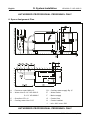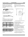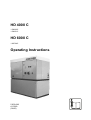
1
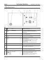
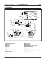
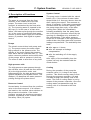
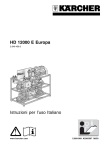
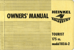
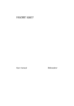
HD 4000 C
1.509-035
1.509-515
HD 6000 C
1.967-045
Operating Instructions
5.956-648
A 10369
(06/00)
Operating Instructions
Please read before operating the unit,
and keep in a safe place for future reference.
Proper disposal – for the sake of our environment
Packaging materials
i
The packaging components used to ship
the unit are composed of wood and
cardboard, i.e., environment-friendly
materials, both of which can be easily
sorted out and collected for recycling.
Important!
Waste oil may be disposed of only at
designated collection points. Please take
used oil to these special installations.
Remember: It is an offence to contaminate
the environment with waste oil!
Operating media
Cleaning detergents
Engine oil
All Kärcher cleaning detergents, as
indicated by the ‘ASF’ designation, are
designed to be separator-friendly. This
means that they do not impede the function
of oil separators. A listing of the
recommended cleaning detergents is
featured in the “Accessories” section.
The equipment contains engine oil. Any
waste oil collected during an oil change, as
well as any oil-water mixture exiting from
the machine in conjunction with a leak,
must be collected and delivered to a wasteoil collection point.
HD 4000 C / HD 6000 C
A.
1.
2.
3.
4.
5.
6.
7.
8.
9.
10.
11.
12.
13.
B.
1.
2.
3.
4.
5.
6.
Table of Contents
For Your Safety
System Operating Hazards
Safety Information and Instructions
Danger Sources
Hazards posed by Accessories
Noise Protection
Workplaces
Authorised Operators
Personal Protective Equipment
Safety Measures on the Installation
Site
Protective Devices
Emergency Drill
Guidelines and Regulations
Proper Use of the Equipment
System Operation
Operating Controls
Using Emergency-STOP
Starting the System
Stopping the System
Frost Protection
System Shut-Down
D.
1.
2.
3.
Specifications
Equipment Features
Connected Loads
Dimension Diagram
E.
1.
2.
3.
4.
Maintenance
Maintenance Contract
Maintenance Schedule
Removing the Cover
Decalcification
English
F. Trouble Shooting
G.
1.
2.
3.
4.
5.
6.
System Installation
Placement
Connections
High-pressure Installation
Hard-water Treatment
Preparations for Commissioning
Space Assignment Plan
H. Accessories
J. Customer Service
C. System Functions
1. Flow Diagram
2. Description of Functions
5.956-648 A10369 (06/98)
1
English
A. For Your Safety
HD 4000 C / HD 6000 C
1. System Operating Hazards
3. Danger Sources
This system is equipped with an
overpressure protection feature which was
subjected to a safety inspection. Improper
operation or abuse of this feature
constitutes an hazard to health and life of
the operator and/or third persons.
Sections of the water volume contained in
the system are under high pressure. Highpressure water jets may exit from damaged
system components, posing injury and/or
scalding hazards.
Any persons charged with the installation,
commissioning, operation, maintenance or
service of the machine are obligated:
n to be appropriately qualified
n to diligently observe these Operating
Instructions
2. Safety Instructions and
Information
Throughout the present Operating
Instructions the following symbols are used:
!
Danger!
Denotes an immediate and present danger.
Failure to observe this notice could lead to
severe injury or death.
Caution!
Denotes a potentially hazardous situation.
Failure to observe this notice could lead to
minor injuries or property damage.
i
Important!
Denotes operating hints and important
information.
General Hazard Overview
!
Danger!
n Injury hazard through exiting water jet of
high-pressure or high-temperature water.
Even after the Emergency-STOP master
switch has been activated, the system
contains high pressure. After a system
stop, release remaining system pressure
by opening a high-pressure gun.
n Burn injury hazard through hot system
components.
During hot-water operation, do not touch
non-insulated pipe installations and hose
couplings. Grasp the jet lance by the
grip surfaces only.
n Injury hazard through flying debris.
Flying debris or objects can cause injury
to persons or animals. Never aim the
water jet at fragile or loose objects.
n Explosion hazard
The use of this system in enclosed
indoor areas is prohibited.
n Explosion hazard
Injury hazard arising from system
damage.
Beside water, no other liquid media may
be used. This also precludes the
introduction of flammable or corrosive
liquids to the system.
n Health hazard through cleaning
detergents.
Due to the possible adding of detergents
to the system water, the water exiting
from the system must not be used as
drinking water.
A1
5.956-648 A10369 (06/98)
HD 4000 C / HD 6000 C
A. For Your Safety
Hazards posed by defective equipment
!
Danger!
Injury hazard through exiting water jet of
high-pressure or high-temperature water.
Before each system start, check highpressure hose, tubing, valves and highpressure lance for damages.
Replace leaking components immediately,
and correct any leaks in connections or
couplings without delay.
Hazards during work on the system
Repair or service work may be carried out
only by:
n manufacturer-approved customer service
depots
n trained professional personnel
!
Danger!
n Injury hazard through exiting water jet of
high-pressure or high-temperature water.
Release system pressure before
performing work on system components.
In the case of hot-water operation, allow
unit to cool before commencing work.
!
English
Danger!
n Injury hazard.
Hazard of chemical burns caused by
cleaning detergents.
Scalding hazard through hot water.
Do not aim waterjet at persons or animals.
Strictly observe safety instructions on
detergent labels.
n Accident hazard due to hidden damage.
Clean tires and valve stems from a
minimum distance of 30 cm.
n Injury hazard through exiting water jet of
high-pressure or high-temperature water.
Only original Kärcher high-pressure
hoses are optimised for the demanding
use in the system.
No warranty claims are accepted in the
event that other types of hoses are used.
The waterjet exiting from the spray lance
causes a recoil force which is deflected
upward by the downward angle of the spray
lance nozzle.
!
n Electric shock hazard.
Switch OFF and secure master switch
before commencing work on the system.
4. Hazards posed by Accessories
A sharp and powerful waterjet exits from
the orifice of the spray lance nozzle. When
operating the spray lance, keep in mind the
following:
!
Danger!
n Deadly electrical shock hazard.
Do not aim the waterjet at
– electrical devices and systems
– at any parts of the system proper
All live components within the working
area must be spray-water protected.
5.956-648 A10369 (06/98)
n Injury hazard through recoil action.
The force of the recoil action may throw
you off balance, and you may fall down.
The spray lance may whip around and
injure persons standing nearby.
Select a secure foothold position and
firmly grasp the handgun.
Never wedge the handgun trigger in the
open position.
n Injury hazard through defective hose
coupling.
Check hose coupling daily for tightness
and absence of leakage.
A2
English
!
A. For Your Safety
7. Authorised Operators
Danger!
n Health hazard posed by toxic
substances.
Do not spray clean the following
materials, because substances known to
pose a risk to human health may be
swirled up:
– Materials containing asbestos
– Materials that could possibly contain
toxic substances hazardous to human
health.
n Poisoning hazard
Chemical burn hazard
Fire hazard
Protect cleaning detergent storage
against access by unauthorised persons.
Observe all safety instructions for
cleaning detergents.
5. Noise Protection
The system generates a sound level of
approximately 80 dB (A), with the use of
sound dampening, this is reduced to 70 dB
(A). Therefore, hearing protection at the
system installation site is not mandatory.
However, at the workplace proper, (i.e.,
handgun) a noise hazard must be assumed
to be present under normal circumstances
(pursuant to Regulation VBG 87).
Accordingly, suitable hearing protection
must be worn while working in noisepolluted areas.
6. Work Stations
The operator’s work station is located at
the instrument panel. Dependent on the
system configuration, additional work
stations are constituted by the accessories
(spraying devices) that are connected to
the system taps.
A3
HD 4000 C / HD 6000 C
The operation of the system is restricted to
persons over the age of 18 who have been
properly instructed. An exception is made
with youths over age 16 who need to
operate the system as part of their training,
and if such use of the system is duly
supervised (Regulation VBG 87).
Additional local ordinances must be
observed.
The system operator is responsible for third
persons within the working area.
The areas of responsibility covering the
various operator functions on the machine
must be precisely delineated and
stringently observed.
Overlapping areas of competence present a
safety risk.
The system owner is responsible for:
n making the Operating Instructions
available to the system operator
n ensuring that the operator has read and
understood the Operating Instructions
8. Personal Protective Equipment
When cleaning resonating
components, hearing protection
must be worn to prevent hearing
loss.
n For protection against spray-water, water
repellent protective clothing must be
worn.
9. Safety Measures on the
Installation Site
!
Danger!
Danger of Death posed by system
components toppling or falling over.
To assure reliable footing, the system must
be securely anchored on a level and firm
base.
5.956-648 A10369 (06/98)
HD 4000 C / HD 6000 C
A. For Your Safety
10. Protective Devices
System operation is stopped by the
Emergency-STOP master switch
located at the instrument panel.
n Inadvertent contact with all hot system
components is prevented by the
protective housing.
English
Please also observe local regulations
concerning electrical connections, water
supply and waste-water connections. The
applicable regulations may be obtained
from the respective utility companies.
Any connection and installation work in
accordance with the aforementioned
regulations must be carried out by the
Kärcher customer service or authorised
contractors.
11. Emergency Drill
Disable the system by activating
the Emergency-STOP master
switch.
n Release water pressure by opening a
high-pressure spray gun.
12. Guidelines and Regulations
In the Federal Republic of Germany the
operation of this system is subject to the
Regulations for Liquid Spraying Devices
(VBG ZH 1/406), published by the Principal
Organisation of the Commercial Employers’
Liability Insurance Association. The
guidelines may be ordered from Carl
Heymann Verlag KG, Luxemburger Strasse
449, D-50939 Cologne, Germany.
Among other requirements, the Regulations
foresee a system inspection by a certified
professional in intervals of no more than 12
months. The results of the inspection must
be documented in writing.
A testing log for entering the inspection
results is located at the end of this manual.
Kärcher customer service engineers qualify
as certified professionals, and are
authorised to carry out the aforementioned
inspection.
13. Proper Use of the Equipment
This system conveys water under high
pressure to high-pressure cleaning stations
situated downstream of the system. The
system is designed for stationary
installation in a dry indoor environment. At
the installation site, a water and mains
power connection satisfying the criteria
stated in the Specifications section of this
manual must be provided. The
environmental temperature at the
installation site must not rise above 40 °C.
The high-pressure water is distributed via a
fixed-installation tubing network.
Only clean water may be used as a highpressure medium. Water contamination of
any kind would cause premature
component wear or lead to deposits within
the system.
In the presence of water hardness
exceeding 15°dH appropriate water
treatment measures for lowering the
hardness point.
The use of recycling water requires prior
discussion with Kärcher.
Also applicable are the (German)
Regulations governing liquid spraying
devices, VBG 87, and the Ordinance on
Hazardous Substances VBG ZH 1/220
(GefStoffV).
5.956-648 A10369 (06/98)
A4
B. System Operation
English
HD 4000 C / HD 6000 C
1. Operating Controls
3
6
7
1
4 5
2
9
1
Emergency-STOP master switch
Q1
Switches the system ON and OFF; also serves as
Emergency-STOP switch.
2
Unlock button with operational
indicator light
starts the availability time of the pump by the press of the
button serves for resetting after malfunctions
is alight when the pump is running and during the
availability time
3
Pressure gauge
Indicates the pressure downstream of the pump; also
serves as function control.
4
Indicator lamp – Motor Fault
Illuminates when the motor protection switch has tripped,
switching off the motor (motor fault).
5
Indicator lamp – General Fault
is illuminated for:
– motor malfunction
– drop in system pressure (at high-pressure outlet)
– water temperature too high
– motor temperature or oil temperature too highinsufficient water
– admission pressure of hot-water pump too low.
6
Elapsed-hour meter
Counts the total pump operating hours.
7
Warning Label
Danger!
Danger of Death by electrical shock!
Control cabinet may be opened by trained personnel only
8
Control cabinet closure
Used for opening the control cabinet
May be opened by trained personnel only
Fault indication on the printed
circuit board
indicates following malfunctions:
1 insufficient water, water temperature too high
2 motor or oil temperature too high
3 admission pressure of hot-water pump too low
4 drop in pressure at high-pressure outlet
9
B1
8
1 2 3 4
5.956-648 A10369 (06/98)
HD 4000 C / HD 6000 C
B. System Operation
2. Using Emergency-STOP
Turn the Emergency-STOP master
switch to the 0 (OFF) position.
n Open the handgun until the water
pressure has dissipated.
n Using the locking feature, secure the
handgun against being opened
inadvertently.
3. Starting the System
Before commissioning this system it is
essential that you read the Operating
Instructions, and to be certain that you
have understood all the information
presented herein.
!
Danger!
n Injury hazard through exiting water jet of
high-pressure or high-temperature
water. Before each system start, check
high-pressure hose, tubing, valves and
high-pressure lance for damages.
Correct any leaks in connections or
couplings without delay.
n Poisoning hazard or chemical burn
hazard through cleaning detergents.
Observe all safety instructions on
cleaning detergent labels. Protect
cleaning detergent storage against
access by unauthorised persons.
A sharp and powerful waterjet exits from
the orifice of the spray lance nozzle. When
operating the spray lance, keep in mind the
following:
!
Danger!
n Deadly electrical shock hazard.
Do not aim the waterjet at
– electrical devices and systems
– at any parts of the system proper
All live components within the working
area must be spray-water protected.
5.956-648 A10369 (06/98)
!
English
Danger!
n Injury hazard.
Hazard of chemical burns caused by
cleaning detergents.
Scalding hazard through hot water.
Do not aim waterjet at persons or
animals.
Strictly observe safety instructions on
detergent labels.
n Burn injury hazard through hot system
components.
During hot-water operation, do not touch
non-insulated pipe installations and hose
couplings. Grasp the jet lance by the
grip surfaces only.
n Injury hazard through recoil action.
The force of the recoil action may throw
you off balance, and you may fall down.
The spray lance may whip around and
injure persons standing nearby.
Select a secure foothold position and
firmly grasp the handgun.
Never wedge the handgun trigger in the
open position.
n Injury hazard through flying debris.
Flying debris or objects can cause injury
to persons or animals. Never aim the
water jet at fragile or loose objects.
n Health hazard posed by toxic substances.
Do not spray clean the following
materials, because substances known to
pose a risk to human health may be
swirled up:
– Materials containing asbestos
– Materials that could possibly contain
toxic substances hazardous to human
health.
n Accident hazard due to hidden damage!
Clean tires and valve stems from a
minimum distance of 30 cm.
n Injury hazard through exiting water jet of
high-pressure or high-temperature water.
Only original Kärcher high-pressure
hoses are optimised for the demanding
use in the system.
No warranty claims are accepted in the
event that other types of hoses are used.
B2
B. System Operation
English
!
HD 4000 C / HD 6000 C
5. Frost Protection
Danger!
n Health hazard through cleaning
detergents.
Due to the possible adding of
detergents to the system water, the
water exiting from the system must not
be used as drinking water.
Switching the System ON
Open the water tap for water
supply and cooling water.
Turn the Emergency-STOP
master switch (Q1) to the I (ON)
position.
Press the unlock button (S1).
The water-bearing parts of the system must
be protected from freezing, since they
could otherwise be destroyed. If the system
is to be operated also in freezing
temperatures, it must be installed in a frostfree location. Outdoor water lines must be
frost-protected (i.e., through insulation or
line heaters, or by draining during freezing
temperatures).
6. System Shut-Down
If a system is to be shut down during cold
periods, it must first be flushed with an
antifreeze solution. As a rule, antifreeze
products also contain corrosion inhibitors.
n Carry out the cleaning procedure. The
pump stops for a cleaning break of
more than 15 seconds. At the same
time the 6 hours of continuous
availability time is started.
Within the availability time the system
starts automatically owing to the drop
in pressure when opening a handgun.
Restoring Operational Readiness
Press the unlock button (S1).
4. Stopping the System
Turn the system’s EmergencySTOP master switch to the 0
(OFF) position.
Shut OFF the water supply.
Open the handgun until the water
pressure has dissipated.
Using the locking feature, secure the
handgun against being opened
accidentally.
B3
5.956-648 A10369 (06/98)
HD 4000 C / HD 6000 C
C. System Function
English
1. Flow Diagram
15
1
2
3
4
5
6
7
8
High-pressure pumps
Float valve
Dirt trap
Overflow
Low-water sensor
Pressure relief valve
Filter
Overflow valve
5.956-648 A10369 (06/98)
9
10
11
12
13
14
Flow monitor
Safety valve
Solenoid valve (cooling water)
Pressure controller
Dashpot
Precompression pump
(with hot-water attachment unit only)
15 Pressure switch
C1
English
C. System Function
2. Description of Functions
Water Inlet
The water is conveyed from the float
reservoir to the intake side of the two
pumps. The water level in the float
reservoir is maintained by the float valve
(2). The incoming water is cleaned in the
dirt trap (3). In the case of a float valve
failure, the water exits through the overflow
(4). In the event of insufficient feed water
volume or failed water supply the low-water
sensor (5) sends a fault signal to system
control.
Pumps
The electric motor drives both pump ends
(1). The pumps convey the water under
high pressure to the pressure side. The
starting of the motor opens the pressure
relief valve with its upstream filter (7). This
action connects pressure and suction sides
of the pumps, and no pressure is built up.
The motor is able to start free of any load.
HD 4000 C / HD 6000 C
System Control
The pump motor is started with the unlock
button (S1). If the volume of water taken
drops below 8 +2 litres per minute, then the
after running time starts. This amounts to
about 15 seconds. If the water consumption
remains below the minimum quantity, then
the pump stops after expiry of the after
running time. Within the immediately
following availability time the pump starts
due to the drop in pressure caused by the
opening of a handgun or by activation of
the unlock button. If the water pressure
drops due to leakages in the high-pressure
network then the pump starts and executes
leakage compensation. The availability time
ends
n after approx. 6 hours,
n after six attempts at leakage
compensation,
n after the switching off of the supply
voltage.
After expiry of the availability time the
system can only be restarted with the
unlock button.
High-pressure side
The high-pressure water passes through
the overflow valve (8) and the flow monitor
(9) to the high-pressure outlet, and
subsequently into the high-pressure tubing
system installed by the system owner. The
dashpot (13) dampens the water pressure
pulsing through the piston sleeve.
Pressure Control
Unused water is returned from the overflow
valve to the float reservoir. If all utilisers
are inactive, the overflow valve switches to
idle-pressure circulation. If the outlet
pressure exceeds the maximum operating
pressure regardless of the overflow valve,
the safety valve (10) opens.
C2
Cooling
During the operation of the pump the
solenoid valve (11) is kept in the open
position. This allows cooling water to flow
through the pressure regulator (12) and
circulate through the cooling coils of the
motor. The flow of cooling water is set by
means of the pressure controller. Once the
cooling water has passed through the
cooling coils it is returned to the float
reservoir.
5.956-648 A10369 (06/98)
D. Specifications
HD 4000 C / HD 6000 C
English
1. Equipment Features
HD 4000 C
1.509-035
HD 4000 CH
1.509-115
HD 4000 C
Scandinavia
1.509-515
HD 4000 C
Scandinavia
1.509-515
with hot-water
accessory kit
2.638-689
Supply volume
L/h
3900
3900
3900
3900
Operating pressure*
bar
100
100
100
100
Max. operating pressure
(safety valve)
bar
130
130
130
130
Length
mm
1090
1090
1090
1090
Width
mm
615
615
615
615
Height (without pedestal)
mm
1070
1070
1070
1070
Weight (empty)
kg
245
245
245
245
Float reservoir
(max. capacity)
L
63
63
63
63
Pump housing
(motor oil, order no. 6.288-061
1-Litre packaging)
L
2 x 1.8
2 x 1.8
2 x 1.8
2 x 1.8
Sound level
dB(A)
approx. 80
approx. 80
approx. 80
approx. 80
Sound level
(sound-insulated version)
dB(A)
approx. 70
approx. 70
approx. 70
approx. 70
Dimensions:
Capacity:
* upon request, lower values can be set by customer service.
5.956-648 A10369 (06/98)
D1
English
D. Specifications
HD 4000 C / HD 6000 C
1. Equipment Features
HD 6000 C
1.967-045
HD 6000 C
1.967-045
with hot-water
accessory kit
2.638-697
Supply volume
L/h
5600
5600
Operating pressure*
bar
60
60
Max. operating pressure
(safety valve)
bar
90
90
Length
mm
1090
1090
Width
mm
615
615
Height (without pedestal)
mm
1070
1070
Weight (empty)
kg
260
260
Float reservoir
(max. capacity)
L
89
89
Pump housing
(motor oil, order no. 6.288-061
1-Litre packaging)
L
2 x 1.8
2 x 1.8
Sound level
dB(A)
approx. 80
approx. 80
Sound level
(sound-insulated version)
dB(A)
approx. 70
approx. 70
Dimensions:
Capacity:
* upon request, lower values can be set by customer service.
D2
5.956-648 A10369 (06/98)
D. Specifications
HD 4000 C / HD 6000 C
English
2. Connected Loads
HD 4000 C
1.509-035
HD 4000 CH
1.509-115
HD 4000 C
Scandinavia
1.509-515
HD 4000 C
Scandinavia
1.509-515
with hot-water
accessory kit
2.638-689
Mains power:
Power type
3 ~ 50 Hz
3 ~ 50 Hz
3 ~ 50 Hz
3 ~ 50 Hz
400, IEC 38
400, IEC 38
220 to 240
220 to 240
15
15
15.5
15.5
Voltage
V
Nominal load (max.)
with water temp. of 20 °C
kW
Power supply cable
mm²
4 x 10
4 x 10
4 x 16
4 x 16
Control cable
mm²
5 x 1.5
5 x 1.5
5 x 1.5
5 x 1.5
A
slow
50
50
63
63
Motor starter (type)
External pre-fusing
Water:
Flow volume
L/h
3900
3900
3900
3900
Max. supply temperature
°C
60
80
60
80
Min. flow pressure
bar
2
2
2
2
Max. flow pressure
bar
6
6
6
6
Supply line, nominal dia.
mm
25
25
25
25
L/h
200 to 220
200 to 220
200 to 220
200 to 220
°C
approx. 10
to 18
approx. 10
to 18
approx. 10
to 18
approx. 10
to 18
Cooling water:
Flow volume
Supply temperature
Min. flow pressure
bar
2
2
2
2
Max. flow pressure
bar
8
8
8
8
Supply line, nominal dia.
mm
15
15
15
15
5.956-648 A10369 (06/98)
D3
English
D. Specifications
HD 4000 C / HD 6000 C
2. Connected Loads
HD 6000 C
1.967-045
HD 6000 C
1.967-045
with hot-water
accessory kit
2.638-697
Mains power:
Power type
3 ~ 50 Hz
3 ~ 50 Hz
400
400
15
15
Voltage
V
Nominal load (max.)
with water temp. of 20°C
kW
Power supply cable
mm²
4 x 10
4 x 10
Control cable
mm²
5 x 1.5
5 x 1.5
A
slow
50
50
Motor starter (type)
External pre-fusing
Water:
Flow volume
L/h
5600
5600
Max. supply temperature
°C
60
80
Min. flow pressure
bar
2
2
Max. flow pressure
bar
6
6
Supply line, nominal dia.
mm
40
40
Flow volume
L/h
250
250
Supply temperature
°C
approx. 10 to 18
approx. 10 to 18
Min. flow pressure
bar
2
2
Max. flow pressure
bar
8
8
Supply line, nominal dia.
mm
15
15
Cooling water:
D4
5.956-648 A10369 (06/98)
HD 4000 C / HD 6000 C
D. Specifications
English
3. Dimension Diagram
5.956-648 A10369 (06/98)
D5
English
E. Maintenance
1. Maintenance Contract
Only a properly maintained system is really
safe. It is in your best interest to ensure
that regular system maintenance
procedures are carried out according to the
maintenance schedule outlined below.
You may wish to enter into a maintenance
contract with the authorised Kärcher
customer service in your area.
A maintenance contract is highly
recommended.
2. Maintenance Schedule
In system maintenance, use only original
parts supplied or recommended by the
manufacturer. Observe all safety and
operating instructions packaged with these
spare parts. In particular, this applies to:
!
HD 4000 C / HD 6000 C
Danger!
n Accident hazard through improper
maintenance procedures!
Without exception, maintenance work
and service repairs must be performed
by personnel or by the Kärcher customer
service.
n Injury hazard through exiting water jet of
high-pressure or high-temperature water.
Release system pressure before
performing work on system components.
In the case of hot-water operation, allow
unit to cool before commencing work.
n Electric shock hazard.
Switch OFF and secure master switch
before commencing work on the system.
n Spare parts and wearing (consumable)
parts
n Accessory parts
n Operating media
n Cleaning media.
E1
5.956-648 A10369 (06/98)
HD 4000 C / HD 6000 C
E. Maintenance
English
a
b
c
d
e
f
g
h
j
k
l
m
5.956-648 A10369 (06/98)
Safety valve
Pump side
Pressure controller
Solenoid valve (cooling water)
Drip pan
Pressure relief valve
Cooling coil
Float reservoir with float valve
Overflow valve, pressure switch
Flow monitor
Oil level sight glass
Dashpot
E2
E. Maintenance
English
HD 4000 C / HD 6000 C
Interval
Procedure
Subject Assembly
Activity
By whom
Daily
Check
handgun
All handguns
Check whether handgun closes
properly. Check function of
safeguard against inadvertent
operation. Replace defective
handguns.
Operator
Check
Outlet lines & hoses leading Check hoses for damage. Replace
high-pressure to workstations
defective hoses immediately.
hoses
Accident Hazard!
Weekly, or Check system Entire system
after 40
for leaks
operating
hours
Check pump, overflow valve and
Operator/
tubing installation for leaks. If oil is
Customer
present in the drip pan under pump, Service
of if a leak exceeds 10 drops of
water per minute, call customer
service immediately.
Keep weep holes unblocked.
Check oil level Both pump sides
Check pump oil level. MIN level:
Centre of oil sight glass. MAX level:
up to mark in housing. If required,
top up with oil (part no. 6.288-061).
Operator
Check oil
quality
Both pump sides
If the oil appears milky, it must be
changed. In this case it is
recommended to change the pump
oil seal also.
(Customer service.)
Operator/
Customer
Service
Check
working
pressure
Pressure gauge in control
panel
Check system water pressure
(pressure gauge). If pressure is too
high or too low, investigate and
remedy the cause (see also the
section on Trouble Shooting).
Operator
Pump must be running.
Check for leakage in tandem and
individual operation.
Connect clutch and check clutch
locking function.
Replace defective clutches.
Operator
Check hose
Hose quick-couplings
quick-coupling between system tap and
high-pressure hose to
handgun.
Check
dashpot
E3
Operator
Customer
Service
Dashpot on each pump side A defective dashpot is readily
Operator
identifiable through increased pump
vibration.
Customer
Replace defective dashpot.
Service
5.956-648 A10369 (06/98)
E. Maintenance
HD 4000 C / HD 6000 C
Interval
Procedure
Subject Assembly
monthly, or Check
Overflow valve
after 200
overflow valve
operating
hrs.
Activity
English
By whom
Dependent on the number of
Operator
high-pressure handguns used, the
pressure reading fluctuates between
the preset value and approx. 15 bar
below the same. On closing all
handguns, the gauge will read
approx. 0 bar. In the event of
malfunction, call customer service.
Customer
service
Check
low-water
sensor
Float switch in float
reservoir
For about 5 seconds press down the
float of the low water protection
facility and check the fault indication
on the printed circuit board. If
necessary remove any deposits.
Trained
operator
authorised
to open
control
cabinet
Clean
strainers
Dirt trap upstream of float
reservoir,
Pressure controller
Switch OFF unit, turn OFF water,
release pressure. Disassemble and
clean strainers.
Operator
Check float
valve
Float reservoir
Water level must stand 40 mm
Operator
below the overflow weir. With float
valve closed, no water may exit. For
adjustment information, refer to the
Service Manual.
Check
Pressure relief valve on
pressure relief pump
valve
When functioning correctly, the
motor must reach full RPM within
2 seconds. If required, clean the
strainer upstream of the pressure
release valve. Prior to cleaning:
Shut OFF water, set EmergencySTOP master switch to OFF.
Operator
Check run-on
interval
System control
Close utiliser (e.g. handgun).
After the after running time (approx.
15 sec) the pump must switch off.
Operator
Check
automatic
switching on
Pressure switch
The pump is stationary as no water
is being drawn. Open the handgun.
When the pressure in the
high-pressure network drops below
25 bar, the pump must switch on.
Operator
Tighten hose
clamps
All hose clamps in/on the
unit
Tighten hose clamps with torque
wrench.
Torque:
28 mm nominal diameter: 2 Nm
29 mm nominal diameter: 6 Nm
Operator
5.956-648 A10369 (06/98)
E4
E. Maintenance
English
HD 4000 C / HD 6000 C
Interval
Procedure
Subject Assembly
Activity
Semiannually,
or after
1000
operating
hours
Oil change
All high-pressure pumps
CAUTION!
Operator
Hot Oil Scalding Hazard.
Prior to oil change, allow pump to
cool for 15 minutes.
Drain oil and fill pump on each side
with 1.8 L oil, part no. 6.288-061. Do
NOT use alternate oil products!
Annually
E5
By whom
Check unit for Entire water system
lime deposits
Functional faults on valves or pumps
may indicate calcification. Use
procedures outlined on the following
pages.
Operator
trained in
decalcificat
procedures
Tighten
Control cabinet
terminal strips
Tighten all terminal strips of
components master mains power
circuit.
Electrician
Safety check
Safety inspection pursuant to
guidelines covering liquid spraying
devices. Refer to section A.12.
Expert/
Customer
service
Entire system
5.956-648 A10369 (06/98)
HD 4000 C / HD 6000 C
E. Maintenance
3. Removing the Cover
Certain repair or service procedures may
require the removal of the cover.
Proceed as follows:
n Remove cover, “A”.
n Remove both cover retaining screws, “B”.
n Slide off cover horizontally, as indicated
by the arrow.
English
These products are balanced for use in
conjunction with the materials present
throughout the system. After decalcification
we recommend neutralising the remaining
acid residues by flushing the system with an
alkaline solution (pH value 7–8).
The instructions for use and accident
prevention regulations (dilution according to
label specifications), and in particular VBG1,
§ 4, 14, and 44–47 must be observed.
Proceed as follows:
Begin by decalcifying the float reservoir:
4. Decalcification
!
Danger!
Explosion hazard through flammable gases!
Smoking is prohibited when carrying out
decalcification procedures. Ensure
adequate ventilation.
Caution!
Acid hazard!
Protective goggles and gloves must be
worn.
Lime deposits throughout the water lines of
the high-pressure system create increased
pipe-run resistance and may result in the
failure of calcified components.
According to official regulations, only
approved boiler scale dissolvants (descaling acid) with test mark may be used.
For scale removal in the high-pressure
system, the use of KÄRCHER scale
dissolvants should be given preference
(RM 100 ASF, hydrochloric acid-free, part
no. 6.287-008, or RM 101 ASF, containing
hydrochloric acid, part no. 6.287-013).
5.956-648 A10369 (06/98)
Close water supply.
Remove cover as discussed in para. 3,
above. Remove the float reservoir lid.
Remove the hose connecting the pump
suction side with the float reservoir, pump
side. Block the free end of the hose. Pour in
7-percent de-scaling solution. After the
conclusion of decalcification, remove all scale
residues from the reservoir!
Decalcifying high-pressure system:
Disconnect high-pressure hose from water
supply inlet and hang into float reservoir.
Next, use the decalcifying acid solution premixed in the float reservoir for shortterm
system operation in circulation (idle pressure)
mode. Allow chemicals to activate, and
conclude by flushing the system.
Decalcifying the cooling coil for the pump
motor:
If the flow of cooling water falls below the
prescribed rate (see Technical specifications), in spite of sufficient input pressure
and a clean strainer in the pressure reducer,
then the cooling coil must be decalcified.
Close the cooling water supply.
Remove, i.e., pull off, the water hose from
the solenoid valve and hang into a catch
container. Remove cooling water hose from
float reservoir, position open end of hose at
suitable height and fill with de-scaling
solution. Allow to activate and conclude by
flushing repeatedly.
E6
English
F. Trouble Shooting
HD 4000 C / HD 6000 C
Problem
Possible Cause
Remedy
by whom
High-pressure
pump fails to
come up to
pressure
Leaking suction-side tubing
system
Check fastener and hose
connections
Operator
Water starvation
Correct the cause
Operator
Defective valve in pump
High-pressure solenoid valve
fails to close
Replace valves
Customer
Service
Pronounced pump Defective dashpot
knock, pressure
Pump is drawing air
gauge pointer
oscillates
Defective valve seat or valve
spring
replace
Operator
Check suction line
Operator
Replace as required
Customer
Service
With hot-water
accessory kit only
Defective or calcified
precompression pump
Check precompression
pump
Operator
Overflow volume
is blown out into
open, and/or
safety valve is
activated
Blown hose between overflow
valve and float valve
replace
Operator
Defective overflow valve
CAUTION: For safety reasons,
excess water is vented
outdoors.
Shut down the system!!
Repair or exchange
overflow valve
Customer
Service
Decalcify system circuits
(refer to Maintenance
section)
Operator
Check spray lances
Operator
Defective overflow valve
Check overflow valve
Cust. Service
Overflow valve
cycles ON and
OFF despite zero
usage
Leak in high-pressure system,
defective spray gun.
Repair leak
Operator
Leaking non-return valve or
control piston seal in overflow
valve
Repair overflow valve
Customer
Service
Pump does not
reach working
RPM with
and/
or
- starter.
Blocked strainer upstream of
solenoid valve
Clean strainer
Operator
Defective pressure relief
solenoid valve
Replace solenoid valve
Customer
Service
Water is returning System is calcified
to float reservoir
despite full-volume
usage
Defective spray lances and/or
nozzles.
F1
5.956-648 A10369 (06/98)
HD 4000 C / HD 6000 C
Problem
General fault and
“Water supply fault”
LED light up on
printed circuit board
F. Trouble Shooting
English
Possible cause
Remedy
by whom
Insufficient water in
float tank
Check site water supply
Operator
Temperature of the water
inlet too high
Reduce inlet temperature
Operator
Cooling water quantity too
low:
General fault and
“HD pump
temperature fault”
LED light up on
printed circuit board
Strainer in pressure reduction Clean strainer
valve contaminated
Operator
Mains water pressure too low Raise pressure
Operator
Cooling coil calcified,
solenoid valve defective
Decalcify,
replace solenoid valve
Operator
Oil level too low
Check oil level
Customer
Service
Oil change not made, owing
Check pump parts,
to which there is oil carbon
replace as necessary.
under the piston guide shoes, Make an oil change
piston seizing.
Customer
Service
Rotation direction of
precompression pump wrong
Change rotation direction
Electrician
Replace pressure switch
Customer
Service
General fault and
“Admission pressure
of hot-water pump
too low” LED light
Pressure switch
up. (Only with ABS
precompression hot-water
hot water)
pump in the ABS hot water
defective
General fault and
“Drop in system
pressure” LED light
up on the printed
circuit board (flow
without pressure
longer than
15 seconds)
Too many utilisers
simultaneously opened
Close down some utilisers Operator
Pipe burst in the
high-pressure network
Turn off installation and
repair pipeline
Customer
Service
Pressure switch defective
Replace pressure switch
Customer
Service
5.956-648 A10369 (06/98)
F2
English
Motor fault lights up
Available time is less than
6 hours
System does not start up
when unlock button is
pressed, no indicator light
illuminates
F3
F. Trouble Shooting
HD 4000 C / HD 6000 C
Motor protection switch Check voltage of the three Customer
Q1 or Q2 has triggered phases
Service/
owing to overcurrent or
Electrician
drop-out of one phase
of power supply
system
Motor protection switch Set in accordance with
falsely set
circuit diagram
Customer
Service/
Electrician
Pressure at pump
outlet too high
Check pressure, adjust as
necessary
Customer
Service
Site high-pressure
network is leaky
Seal it off
Operator
Pressure switch
defective
Replace
Kundendienst
Site power supply
interrupted
switch on
Operator
Emergency-STOP
master switch off
switch on
Operator
Motor protection switch check
for control system and
precompression pump
has been triggered
Customer
Service /
Electrician
Control-circuit fuse on
transformer defective
replace, check cause
Customer
Service /
Electrician
Printed circuit board
defective, green LED
does not blink
replace, check
Customer
Service
EPROM loose
install again, check cause
Customer
Service /
Electrician
5.956-648 A10369 (06/98)
HD 4000 C / HD 6000 C
F. Trouble Shooting
English
System runs for about 15
sec after pressing the
unlock button and then
switches off. General fault
and “Admission pressure
of hot-water pump too low”
LED light up
Admission pressure of check pump rotation
hot water too low
direction, check water
intake
Customer
Service
Pressure switch
precompression
hot-water pump or
cable in ABS hot
water defective
replace
Customer
Service
Pump starts during
available time but not by
opening the handgun
Pressure switch or
cable to pressure
switch defective
replace
Customer
Service
Unlock button activated,
Pressure switch
“operational” indicator light defective
illuminates, system does
not start up
replace
Customer
Service
While activating the HD
pistols the unit switches
itself off
check flow switch
Customer
Service/
Electrician
Unlock button activated,
“operational” indicator
system starts up,
light defective
“operational” indicator light
does not illuminate
switch Emergency-STOP
master switch Q1 to
position 0, open control
cabinet and verify or
replace components
Customer
Service/
Electrician
System does not switch on Flow switch S2
defective
replace upper part of flow
switch
Customer
Service/
Electrician
Remote start button does
not function
eliminate the cause and
press unlock button
Operator
5.956-648 A10369 (06/98)
Flow switch does not
function
System in a
malfunction state
F4
G. System Installation
English
HD 4000 C / HD 6000 C
AUTHORISED PROFESSIONAL PERSONNEL ONLY
1. Placement
The system must be installed in dry indoor
surroundings free from explosion hazard.
The components shall be placed on firm
and level ground, and the system must be
easily accessible for the purpose of
maintenance procedures. The room
temperature must not exceed 40 °C.
Additional height-over-floor obtained
through the use of the component feet
(140 mm length) facilitates maintenance access. In the absence of sufficient space the
elastic feet can be used by themselves.
2. Connections
The water and waste-water connections, as
well as the connection with the electrical
mains network may only be carried out by
licensed and authorised professional
contractors pursuant to local regulations. In
the Federal Republic of Germany the
following regulations apply:
n VDMA guideline, standardised leaflet
24416 “Fixed-Installation High-Pressure
Cleaning Systems”
n VDE Regulations (VDE = Professional
Association of German Electricians)
In the event of excessive admission
pressure or the occurrence of pressure
peaks in the mains network, the installation
of a pressure regulator upstream of the
system is mandatory.
The motor cooling circuit within the system
requires a separate cold-water connection.
A water drain must be present at the
installation site.
3. High-pressure Installation
The link between the fixed-installation pipe
network and the system must be executed
in the form of a flexible high-pressure hose
connection.
The permanent pipe network installation
must consist of as many straight runs as
possible. All high-pressure tubing must be
installed pursuant to regulations, using
vibration-dampened strain relief and fixed
pipe or tubing clamps, while allowing for
longitudinal expansion/contraction due to
the effects of temperature and pressure.
To keep pressure losses in the highpressure lines as low as possible, the
following recommendations should be used
as mandatory guidelines:
n Regulations issued by local utility
companies
Delivery
volume
Tubing line
Hose size
Both the required water supply and the
electrical mains network connection must
be configured for permanent operation. The
specified connective load values are stated
in the Specifications.
1000 L/h
NW 10 (3/8")
NW 8
2000 L/h
NW 15 (1/2")
NW 12
3000 L/h
NW 15 (1/2")
NW 12
The water supply must be equipped with a
shutoff valve, and must be connected with
the high-pressure by means of a flexible
high-pressure hose. Insufficient supply line
cross section or insufficient admission
pressure will result in water starvation.
To prevent pump damage, a low-water
condition will automatically result in system
shut-down.
4000 L/h
NW 20 (3/4")
NW 16
6000 L/h
NW 25 (1")
NW 20
G1
It should be understood that the above
guidelines still require additional allowances
for the overall tubing length, the number of
directional changes and armatures.
5.956-648 A10369 (06/98)
HD 4000 C / HD 6000 C
G. System Installation
English
AUTHORISED PROFESSIONAL PERSONNEL ONLY
4. Hard-water Treatment
Excessive water hardness (>15° dH) can
lead to deposits and result in malfunctions.
Contact the manufacturer in the event of
unusually high degrees of water hardness.
5. Preparations for Commissioning
n Install float reservoir overflow line
n Check pump oil level. Remove threaded
plug from oil reservoir.
Threaded
plug
n Thoroughly rinse entire HD system
(HD 4000/6000 C also). Check entire HD
system for correct assembly and lack of
leaks.
n Complete electrical connections in
accordance with the Specifications
contained in the Operating Instructions.
n Check the function of decalcifying
component (if required).
n Check water supply for required delivery
volume and maximum allowable
temperature.
n Check cold-water cooling circulation:
Verify cooling water volume (refer to
Specifications) and connection data.
Adjusting cooling water volume
on pressure regulator.
Locking screw
AUTHORISED PROFESSIONAL PERSONNEL ONLY
5.956-648 A10369 (06/98)
G2
G. System Installation
English
HD 4000 C / HD 6000 C
AUTHORISED PROFESSIONAL PERSONNEL ONLY
6. Space Assignment Plan
A : Pressure outlet M30x1.5
D1 : Cooling water supply Rp ½"
B : Water inlet G 1¼" HD 4000 C
E : Water outlet
G 1 ¾" HD 6000 C
F : Mains supply
C : Overflow O.D. 41
G : Control line
D : Cooling water inlet G ¾"
H : Control cabinet
J
: min. 200 / max. 500
AUTHORISED PROFESSIONAL PERSONNEL ONLY
G3
5.956-648 A10369 (06/98)
H. Accessories
HD 4000 C / HD 6000 C
English
Handguns with different spray lances
System tap / workstation
Dependent on the cleaning application,
different spray lance extensions are
required, ranging from 250 mm for onehand operation to 2040 mm for cleaning
high objects.
Features injector for metering cleaning
detergent into pressure side, wall-mounted
container console and hose keeper, remote
release.
Spray lance with bypass valve
Featuring two spray patterns and operation
in conjunction with cleaning detergents,
length approx. 1000 mm.
Nozzles
Several nozzles with different spray angles
are available for the system. The nozzles
are mounted on the spray lance by means
of a union nut, and are easily changed.
Recommended nozzle size is size 07.
Designation
Spraying
angle
Order no.
6.415-
1507
15°
-305
2507
25°
-287
4007
40°
-288
Force of recoil from the handgun when
using these nozzles:
HD 4000 C
100 bar
43 N
HD 6000 C
60 bar
25 N
The spraying device (i.e., handgun) is
connected by means of an in-line quickcoupling.
5.956-648 A10369 (06/98)
Hot-water accessory kit
This accessory kit permits an increase
of the water supply temperature to
a maximum of 80°C.
Cleaning detergents
Cleaning detergents facilitate any cleaning
task. A selection of cleaning agents is
listed in the table on the following page.
When using detergents it is essential to
observe the instructions supplied on the
product labels.
The following types of cleaning detergents
must not be used with this system:
•
•
Detergents containing nitric acid
Detergents containing active chlorine
Using these types of detergents will result
in damage to unit components.
H1
H. Accessories
English
HD 4000 C / HD 6000 C
Area of
application
Contamination type
Application method
Cleaning agent
Automotive,
petrol stations,
motor carriers,
vehicle fleets
Dust, road grime, mineral oils
(on painted surfaces)
RM 55/1000-liquid ASF **
RM 22/80-powder ASF
RM 81-liquid ASF
RM 803-liquid ASF
Vehicle protection
RM 820-hot wax ASF
RM 821-spray wax ASF
RM 824-Super-Perlwachs ASF
Oils,
greases,
dust
and similar
contamination
RM 22-powder ASF
RM 55-liquid ASF
RM 81-liquid ASF
RM 31-liquid ASF
(heavy contamination)
RM 39-liquid
(with corrosion protection)
alkaline
slightly alkaline
alkaline
strongly alkaline
RM 55-liquid ASF
RM 81-liquid ASF
slightly alkaline
alkaline
Metal-working
industry
Food
processing
industry
Sanitary
installations
Light to medium
contamination,
greases/oils
large surfaces
Approx. pH value
1 %-solution
slightly alkaline
alkaline
alkaline
alkaline
neutral
neutral
neutral
slightly alkaline
RM 58-liquid ASF
(foaming cleanser)
RM 31-liquid ASF *
alkaline
strongly alkaline
Smoky resin
RM 33-liquid *
strongly alkaline
Cleaning and disinfecting
RM 32-D-liquid
alkaline
Disinfecting
RM 735-D-liquid
alkaline
Lime,
mineral deposits
RM 25-liquid ASF *
RM 59-liquid ASF
(foaming cleanser)
strongly acidic
acidic
RM 25-liquid ASF
(basic cleaning)
RM 59-liquid ASF
(foaming cleanser)
RM 68-liquid ASF
strongly acidic
Lime,
urinal deposits,
soaps, etc.
acidic
acidic
* = for short-term use only. Two-step method. Flush with clean water.
** = ASF = abscheidefreundlich
H2
5.956-648 A10369 (06/98)
HD 4000 C / HD 6000 C
System Type:
J. Customer Service
Works No.
English
Commissioned: (date)
Inspected:
(date)......................................................................................................
Results/Comments:
......................................
Signature
Inspected:
(date)......................................................................................................
Results/Comments:
......................................
Signature
Inspected:
(date)......................................................................................................
Results/Comments:
......................................
Signature
Inspected:
(date)......................................................................................................
Results/Comments:
......................................
Signature
5.956-648 A10369 (06/98)
J1