1
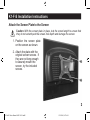
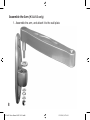
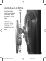
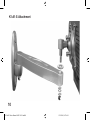
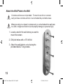
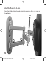
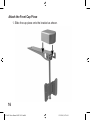
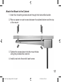
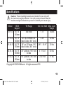
Table of Contents
Before You Begin
2
K1-F-S Installation
3
K1-TS-S & K1-A1-S Installation
6
K2-A1-S Installation
11
K1-UC-S (Under-Cabinet Mount) Installation
15
Specifications
19
1
K1 & K2 Series Manual 6.0W X 4 R1.indd1
12/15/2005, 8:57 AM
Before You Begin
Do not attempt to install this product if you do not understand the
instructions or if there are missing or defective parts. Improper
installation may result in property damage or in personal injury.
STOP
What You Will Need:
• Stud Finder
• Phillips Screwdriver
• Electric Drill
• 1/8” Drill Bit
•
•
•
9/16” Wrench (K1-F-S only)
1/2” Wrench (K2-A1-S only)
1/4” Drill Bit (K1-UC-S only)
To start installation, go to the section pertaining to your specific model. You can
find the page number in the Table of Contents.
2
K1 & K2 Series Manual 6.0W X 4 R1.indd2
12/15/2005, 8:57 AM
K1-F-S Installation Instructions
Attach the Screen Plate to the Screen
!
Caution: With the screen plate in place, test the screw length to ensure that
they do not extend past the screen hole depth and damage the screen.
1. Position the screen plate
on the screen as shown.
2. Attach the plate with the
original screen screws. If
they are not long enough
to securely mount the
screen, try the included
screws.
3
K1 & K2 Series Manual 6.0W X 4 R1.indd3
12/15/2005, 8:57 AM
Attach the Wall Plate to the Wall
!
Concrete anchors are not provided. To mount to a brick or concrete
wall, purchase concrete anchors to accomodate the provided screws.
!
When mounting to a drywall or plaster wall, you should attach the wall plate
to a 2X4 or larger wood stud to avoid property damage or personal injury.
1. Locate a stud in the wall
where you want to mount
the screen.
2. Drill pilot holes with a 1/8”
drill bit.
3. Attach the wall plate to a
stud using the provided
black 2” long screws.
4
K1 & K2 Series Manual 6.0W X 4 R1.indd4
12/15/2005, 8:57 AM
Attach the Screen to the Wall Plate
1. Push the screen plate against
the wall plate and then let it
slide down into place.
2. Fasten the screw through
the screw hole in the bottom
of the bracket until it seats
against the nut.
5
K1 & K2 Series Manual 6.0W X 4 R1.indd5
12/15/2005, 8:57 AM
K1-TS-S & K1-A1-S Installation
Attach the Screen Plate to the Screen
!
Caution: With the screen plate in place, test the screw length to ensure that
they do not extend past the screen hole depth and damage the screen.
1. Position the screen plate on the screen as shown.
2. Attach the plate with the original screen screws. If they are not long
enough to securely mount the screen, try the included screws.
6
K1-TS-S
K1 & K2 Series Manual 6.0W X 4 R1.indd6
K1-A1-S
12/15/2005, 8:57 AM
Attach the Wall Plate to the Wall
!
Concrete anchors are not provided. To mount to a brick or concrete
wall, purchase concrete anchors to accomodate the provided screws.
!
When mounting to a drywall or plaster wall, you should attach the wall plate
to a 2X4 or larger wood stud to avoid property damage or personal injury.
1. Locate a stud in the wall where you
want to mount the screen.
2. Drill pilot holes with a 1/8” drill bit.
3. Attach the wall plate to a stud using the
provided black 2” long screws.
7
K1 & K2 Series Manual 6.0W X 4 R1.indd7
12/15/2005, 8:57 AM
Assemble the Arm (K1-A1-S only)
1. Assemble the arm, and attach it to the wall plate.
8
K1 & K2 Series Manual 6.0W X 4 R1.indd8
12/15/2005, 8:57 AM
Attach the Screen to the Wall Plate
Using the included
inside hex and outside
hex wrenchs, attach
the screen to the wall
plate.
The K1-TS-S is
pictured to the right.
The K1-A1-S is
pictured on the next
page.
9
K1 & K2 Series Manual 6.0W X 4 R1.indd9
12/15/2005, 8:57 AM
K1-A1-S Attachment
10
K1 & K2 Series Manual 6.0W X 4 R1.indd10
12/15/2005, 8:57 AM
K2-A1-S Installation Instructions
Attach the Screen Plate to the Screen
!
Caution: With the screen plate in place, test the screw length to ensure that
they do not extend past the screen hole depth and damage the screen.
1. Position the screen plate on
the screen as shown.
2. Attach the plate with the
original screen screws. If
they are not long enough to
securely mount the screen,
try the included screws.
11
K1 & K2 Series Manual 6.0W X 4 R1.indd11
12/15/2005, 8:57 AM
Attach the Wall Plate to the Wall
!
Concrete anchors are not provided. To mount to a brick or concrete
wall, purchase concrete anchors to accomodate the provided screws.
!
When mounting to a drywall or plaster wall, you should attach the wall plate
to a 2X4 or larger wood stud to avoid property damage or personal injury.
1. Locate a stud in the wall where you want to
mount the screen.
2. Drill pilot holes with a 1/8” drill bit.
3. Attach the wall plate to a stud using the
provided black 2” long screws.
12
K1 & K2 Series Manual 6.0W X 4 R1.indd12
12/15/2005, 8:57 AM
Assemble the Arm
1. Assemble the arm, and attach it to the wall plate.
13
K1 & K2 Series Manual 6.0W X 4 R1.indd13
12/15/2005, 8:57 AM
Attach the Screen to the Arm
Using the included inside hex and outside hex wrenchs, attach the screen to
the wall plate.
14
K1 & K2 Series Manual 6.0W X 4 R1.indd14
12/15/2005, 8:57 AM
K1-UC-S (Under-Cabinet Mount) Installation
Drill the Mounting Holes
1. Remove the contents of
your cabinet.
2. Hold the bracket under
the cabinet where it will
be mounted.
3. Insert a pen or pencil
through the mounting
holes and make marks
where you need to drill.
4. Remove the mount and
use a 1/4” drill bit to drill
holes up through the
cabinet bottom where
marked.
15
K1 & K2 Series Manual 6.0W X 4 R1.indd15
12/15/2005, 8:57 AM
Attach the Front Cap Piece
1. Slide the cap piece onto the bracket as shown.
16
K1 & K2 Series Manual 6.0W X 4 R1.indd16
12/15/2005, 8:57 AM
Attach the Mount to the Cabinet
1. Insert four mounting screws down through the holes drilled earlier.
2. Place a spacer on each screw between the cabinet bottom and the top
of the mount.
3. Tighten the screws down into the mount holes
using the provided hex wrench.
4. Install a nut onto the end of each screw.
17
K1 & K2 Series Manual 6.0W X 4 R1.indd17
12/15/2005, 8:57 AM
Attach the Screen to the Mount
!
Caution: With the screen plate in place, test the screw length to ensure that
they do not extend past the screen hole depth and damage the screen.
1. Position the screen on the screen plate as shown.
2. Attach the plate with the
original screen screws. If
they are not long enough to
securely mount the screen,
try the included screws.
18
K1 & K2 Series Manual 6.0W X 4 R1.indd18
12/15/2005, 8:57 AM
Specifications
!
Caution: These mounting brackets are intended for use only with
the maximum weights indicated. Use with products heavier than the
maximum weights indicated may result in instability and cause injury.
Model
VESA
Support
K1-F-S
60, 75
100mm
K1-TS-S 60, 75
100mm
K1-A1-S 60, 75
100mm
K2-A1-S 60, 75
100mm
K1-UC-S 60, 75
100mm
Tilt Range
Ext. from Wall
360 circle
1.75”
Max. Load
Weight
550 lbs
20° up, 25°down, 60°
side to side, 360° circle
20° up, 25°down, 105°
side to side, 360° circle
30° up/down, 180° side
to side
90° up/down, 360° side
to side
3.38”
30 lbs
2.81” - 10.81”
30 lbs
3” - 15.44”
50 lbs
12.50” min.
11 lbs
Copyright © 2005 K2Mounts. All rights reserved. R0
19
K1 & K2 Series Manual 6.0W X 4 R1.indd19
12/15/2005, 8:57 AM
20
K1 & K2 Series Manual 6.0W X 4 R1.indd20
12/15/2005, 8:57 AM