1
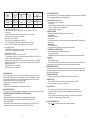
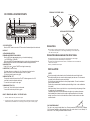
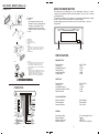
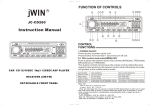
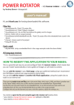
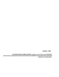
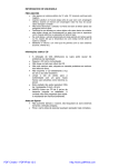
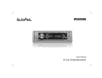
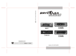
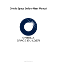
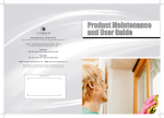
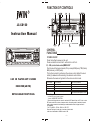
FUNCTION OF CONTROLS
R
17
1 7 19
18
6
5
14 16 9
LUD
C D / C D - R / C D - R W PLAYE R
LUD
3
DISP
PUSH SEL
JC-CD160
RPT
RDM
SCAN
ALL
DIR
SONG
CLASSIC
BND
MUT
CLK
ST
LOC
LUD
JAZZ
MUSIC
MUTE
LOUD
MONO
AF
PTY
EON
60 WATT/DIGITAL TUNING SYSTEM
Instruction Manual
SCN
A/PS
1
2 INT
3 RPT
4 RDM
21
22
23
5
6
MODE
LUD
20
15
2
11
10
12 13 8 4
LUD
C D / C D - R / C D - R W PLAYE R
LUD
PUSH SEL
DISP
RPT
RDM
SCAN
ALL
DIR
SONG
CLASSIC
BND
MUT
CLK
ST
LOC
LUD
CONTROL
FUNCTIONS
JAZZ
MUSIC
MUTE
LOUD
MONO
AF
PTY
EON
60 WATT/DIGITAL TUNING SYSTEM
SCN
A/PS
2 INT
1
3 RPT
4 RDM
5
6
MODE
LUD
CAR CD PLAYER ASP 12/45SEC
RECEIVER(AM/FM)
DETACHABLE FRONT PANEL
1POWER ON/OFF
Press the button to power up the unit
Press and hold for more than 1 second to turn off unit.
2,3. SEL (control mode select)/MENU KEY
Push to select the desired mode,VOL(volume),BAS(bass),TRE(treble)
BAL(balance),or FAD(fader).
This button normally functions as the volume control.Adjust the level
rotate(3) clockwise after selecting the desired control mode.
Otherwise the mode will go back to the volume control mode.
Control Mode
Volume control
Bass control
Treble control
Balance control
Fader control
Turn clockwise:
For less volume
For less bass
For less treble
To decrease the right speaker volume
To decrease the front speaker volume
Turn counter clockwise:
For more volume
For more bass
For more treble
To increase the left speaker volume
To increase the rear speaker volume
MENU KEY
Hold the SEL key to choose the menu.
1) menu1: AUDIO DSP FUNCTION
Press and hold longer than one second to activate the DSP feature.Rotate the SEL knob to select
DSP mode sound effect as shown in sequence below .User setting value of bass/treble in normal
mode is always memorized.In rock/classic/pops mode,bass/treble mode is skipped and level is
not changeable
FLAT----CLASSICS----POP M----ROCK M----DSP OFF.
Bass and Treble gain of each mode is as shown in below table.
Initial value of bass/treble in NORMAL mode is 0 dB.
-- 1 --
LCD DISPLAY
BASS (F=100HZ)
MID (F=1KHZ) TREBLE (F=10KHZ)
X dB
0 dB
X dB
0 dB
0 dB
0 dB
ROCK
DSP OFF
FLAT M
ROCK M
6 dB
0 dB
2 dB
CLASSIC
CLASSIC M
2 dB
0 dB
2 dB
POP
POP M
-4 dB
0 dB
-2 dB
NORMAL
FLAT
2) menu2:BEEP ON--BEEP OFF
The situation of beep sound is selected.The 2 mode is selected as also vol up
or vol dn key.
BEEP ON mode: A beep sound is generated when each key is pressed.
BEEP OFF mode: The beep sound is disabled.
3) menu3:VOL LAST--VOL Addition
VOLUME ELEVEL is determined when POWER ON
LAST VOLUME:Final VOLUME LEVEL generates power before power off.
ADJUST VOLUME:VOLUME LEVEL selected by the user is produced.
4) menu4:SEEK1--SEEK2
SEEK1:SEEK is activated right away when key is pressed for longer than 500ms.
SEEK2:SEEK is activated after key is released.
5) menu5:ESP12--45 OPTION
While ANTI-SKIP PROTECTION FUNCTION (ASP)
If in use,the player is likely to receive shocks or vibrations.The ANTI-SHOCK FUNCTION
is active to provide uninterrupted playback.
Should the player receive shocks for more than 45 seconds continuously in cd playback
playback,the sound will mute for a very short while and will resume once the player has
stabilised from the shock.
ESP12:Selected ESP time 12 seconds.
ESP45:Selected ESP time 45 seconds.
4. LOUDNESS BUTTON
-Press this button to boost the bass and treble response.Push the button again to return to
normal operation.This function is useful when listening at low levels.Loudspeakers are ineffici
ent at low power levels and will tend to sound flat.The loudness control will boost the bass
and treble response thus giving a more lively performance.
While this function is operating,the display shows LUD.
5. LCD DISPLAY
-The liquid crystal display will display the current status of the unit.
6. BAND SELECTOR SWITCH
Press this switch to select the desired Radio band.Selection is made in regular sequence as FM-AM.
7. AUTOMATIC OR MANUAL TUNING(FREQ UP>>OR FREQ DOWN<<)
(A) RADIO MODE
When pressed for less than 1 second,these keys operate as manual tuning mode.
When pressed longer than 1 sec.,they are operated as SEEK tuning mode.(AUTO)
(B) CD PLAYER MODE
When pressed for less than 1 second,these keys operate as TRACK UP or TRACK DOWN.
When pressed longer than 1 sec.,they will operate as CUE or REVIEW mode.
-- 2 --
8. LOCAL/DISTANT BUTTON
Press local/distant(LO/DX) button for listening to weak stations.LOC indicator will appear on the display.
Press this button again (Distant mode) for normal operation.
9. DISPLAY BUTTON (Set the Clock)
Selects radio frequency or clock display.
To set the clock:
1.With clock display selected,hold down the (CLK) button until clock display starts flashing.
2.Press (-) to change minutes,(+) to change hours.
3.Press (CLK) button to start the clock.
10. PRESET STATIONS
Six numbered preset button store and recall stations for each band.
Storing station
1.Select a band (if needed)
2.Select a station
3.Hold a preset button longer than one second.Preset station number appears in the display when
station is saved.
Recall a station:
1.Select band (if needed)
2.Press a preset button for less than one second to select stored station.
11. AUTOMATICALLY STORE STATIONS
Select six strong stations and store them in current band.
1.Select a band (if needed)
2.Hold A/PS button for more than three seconds.The new station replace stations already stored
in that band.
Preset A/PS
1.Select a band (if needed)
2.Touch A/PS for more than one second but less than three seconds.Radio pauses for five seconds
at each station.Touch A/PS again to stop scanning when the desired station is reached.
12.STEREO/MONO SELECTOR
This function will only affect FM reception.Press this button if the FM reception becomes noisy/hissy.
If the station being received is in stereo,it will now be played in mono.Press this button again to return
tthe receiver to normal reception
13.MODE BUTTON (MODE)
By pressing this key,user can select RADIO mode,AUX mode,CD PLAYER mode.
14.MUTE BUTTON
Press the MUTE button to stop and the lcd will flashing indication "MUTE".
To stop this function, press again the same button.
15. SCAN BUTTON
Press this button briefly (LESS THAN 2 SEC.)and the radio will tune to the next
memory preset station, pausing for 6 seconds, and repeating the process endlessly until
a selection is made.
To stop scanning, press this button briefly once again, or press the preset button that
Corresponds to the channel number blinking on display.
16.PANEL RELEASE BUTTON
Press the button and the right-side section of the panel will release.
-- 3 --
REMOVING THE FRONT PANEL
CD CONTROL LOCATION OF PARTS
18
19
17
Front Panel
LUD
C D / C D - R / C D - R W PLAYE R
LUD
Release Button
PUSH SEL
DISP
RPT
RDM
SCAN
ALL
DIR
SONG
CLASSIC
BND
MUT
CLK
ST
LOC
LUD
JAZZ
MUSIC
MUTE
LOUD
MONO
AF
PTY
EON
INSTALLING THE FRONT PANEL
60 WATT/DIGITAL TUNING SYSTEM
SCN
A/PS
1
2 INT
3 RPT
4 RDM
21
22
23
5
6
MODE
LUD
20
17.CD EJECT BUTTON
Press the EJECT button to remove the CD.The receiver will automatically switch to radio mode.
18.CD SLOT
19.TRACK/SEARCH BUTTON
FORWARD AND REVERSE TRACK SEARCH
Press the SKIP button or
during play to go to the desired track(song).
( ....REVERSE)( ....FORWARD)
Press and hold the SKIP button or during play to scan the disc at high speed.When the
desired music section of the disc is found,release the button.Normal play will resume.
20.PAUSE BUTTON
During PLAY ,press button to PAUSE.Press it again to resume play.
21.INT BUTTON (Priview all Tracks)
This feature allowes you to listen to the first 10 seconds of each track on the
display .Press the key SCAN indicator appears on the LCD pannel.
To cancel the function press the key again.
22.REPEAT BUTTON (RPT)
To repeat the current track press the key.The RPT indicator appears on the LCD
panel and the track be repeated continuously.
To cancel the function press the key again.
23.RANDOM BUTTON (RDM)
Press the key. Tracks will be player in randomorder.
To cancel the function the press the key again.
HOW TO REMOVE AND INSTALL THE FRONT PANEL
1.
Press the release button and pull-off the front panel.
2.
To install the front panel, insert the panel into the housing and make sure the panel is securely
installed, otherwise, abnormalities occurs on the display or some keys will not function properly.
PRECAUTIONS
Do not touch the contacts on the front panel or on the unit body, since this may result
in poor electrical conductivety.If dirt or other foreign substances get on the contacts, wiper
them with a clean dry cloth.
PRECAUTIONS WHEN HANDLING THE FRONT PANEL
Do not leave the front panel in any area exposed to high temperatures or direct sunlight.
Do not drop the front panel or otherwise subject it to strong impact.
Do not allow such volatile agents as benzene, thinner, or insecticides to come into contactwith the
surface of the front panel.
Never try to disassemble the front panel.
INSTALLATION
NOTE:
Choose the mounting location where the unit will not interfere with normal driving function.
Before finally installing the unit, connect the wiring temporarily and make sure it is all connected
up properly and the unit and the system work properly.
Use only the parts included with the unit to ensure proper installation. The use of unauthorized
parts can cause malfunctions.
Consult with your nearest dealer if installation requires the drilling of holes or other modifications
of the vehicle.
Install the unit where it does not get in the driver s way and cannot injure the passenger if there
is a sudden stop. Like an emergency stop.
If installation angle exceeds 30 from horizontal the unit might not give optimum performance.
Avoid installating the unit where it would be subject to high temperature.such as from direct
sunlight. Lower case or from hot air,from the heater,or where it would be subect to dust,.dirt or
excessive vibration.
DIN FRONT/REAR-MOUNT
This unit be can properly installed either from Front (conventional DIN Front-mount) or Rear
(DIN Rear-mount installation, utilizing threaded screw holes at the sides of the unit chassis). For
detail, refer to the following illustrated installation methods.
-- 4 --
-- 5 --
DIN FRONT- MOUNT (Method A)
USING THE RESET BUTTON
Installing the unit
2
1
1. Dashboard
2. Holder
After inserting the holder into the
dashboard, select the appropriate tab
according to the thickness of the
dashboard material and bend them
inwards to secure the holder in place.
3. Screw
Press button with a thin, pointed object if unit is malfonctioning. Though not a normal
occurrence, the microprocessor which controls the operation of this unit can be affected
by electrostatic noise.
This generally is indicated by such symptoms as no power being supplied when you switch
the unit on, failure of buttons and controls, or an abnormal display.
Should this happen, press the reset button with a thin, pointed object to reset the
microprocessor.
3
1.
2.
3.
4.
5.
6.
1
6
7
Dashboard
Nut (5mm)
Spring washer
Screw (5 x 16mm)
Screw
Strap
Be sure to use the strap to secure the
back of the unit of the place. The strap
can be bent by hand to the desired
angle.
Plain washer
4
5
2
7.
RESET
FLASHING
3
SPECIFICATIONS
MW(AM) SECTION
1.
2.
1
3.
3
Frame
Insert fingers into the groove in the front
of frame and pull out to remove the
frame .(When re-attaching the frame.
Point the side with a groove downwards
and attach it.)
Lever
Insert the levers supplied with the unit
into the grooves at both sides of the unit
as shown in figure until they click.
Pulling the levers makes it possible to
remove the unit from the dashboard.
4 SPEAKER WIRING
ANTENNA
FUSE
0.5A
GRAY
RED(R)
LINE IN
WHITE(L)
FRONT
LEFT
SPEAKER
REAR
LEFT
SPEAKER
FM SECTION
: 87.5-107.9 MHz
: 200 Khz
: 10.7 MHz
: >50 dB
: >60 dB
CD PLAYER SECTION
RED(R)
WHITE(L)
: 530 - 1710 KHz
: 10 KHz
: 450 KHz
: 33 dB
: >50 dB
: >50 dB
Frequency Range
Channel Step
Intermediate Frequency
Image Rejection Ratio at 106KHz
Signal to noise ratio
CONNECTIONS
LINE OUT
Frequency Range
Channel Step
Intermediate Frequency
Usable Sensitivity
Image Rejection Ratio
If Rejection Ratio
1A
BLACK
7A
GRAY +
+ WHITE
- WHITE/BLACK
GRAY/BLACK-
+ GREEN/BLACK
VIOLET +
- GREEN
VIOLET/BLACK-
-- 6 --
BLACK
GROUND(-)
BLUE
AUTO ANT(+)
RED
B (+)
YELLOW
BACK UP
FRONT
RIGHT
SPEAKER
REAR
RIGHT
SPEAKER
Signal to noise Radio
Channel separation
Frequency Response
: More than 60dB
: More than 60dB
: 20Hz - 20KHz
GENERAL
Power Supply Voltage
Speaker impedance
Maximum Output Power
Dimensions Chassis
: DC 12 Volts Negative Ground
: 4 -8
: 15W x 4CH
: 178(W) x 50 (H) x 160(D)mm
-- 7 --