1
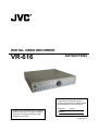
DIGITAL VIDEO RECORDER
VR-616
INSTRUCTIONS
For Customer Use:
Enter below the serial No. which is
located on the bottom of cabinet. Retain
this information for future reference.
Model No:
Thank you for purchasing this JVC product.
Before operating this unit, please read the
instructions carefully to ensure the best
possible performance.
VR-616
Serial No:
LLT0063-001A
JVC VR-616
-CONTENTS1. Impo r tant Safeguards --------------------------------------------------------------------- 6
2. Part Names and Features ----------------------------------------------------------------- 17
2.1 Basic Organization of DVR System ----------------------------------------------------------------- 17
2.2 Features ----------------------------------------------------------------------------------------- 18
2.3 Preparation of installation -------------------------------------------------------------------------------- 20
2.4 Part Name and Description --------------------------------------------------------------------------- 21
3. Explanation and Application --------------------------------------------------------------- 24
3.1 Basic Schematic of the DVR System --------------------------------------------------------------------- 24
3 . 1 . 1 Bas ic Sche mat ic -- - -- - - - - - - - - - - - - -- - - - - - - - - - - - - -- - - - - - - - - - - - - -- - - - - - - - - - - - - -- - - - 24
3 . 2 B a s i c C o n n e c t i o ns - - -- - - - -- - - - - - - - - - - - - -- - - - - - - - - - - - - -- - - - - - - - - - - - - -- - - - - - - - - - - - - -- - 25
3.3 Pan/Tilt Camera Connection and Control -------------------------------------------------------- 26
3.3.1 The example of connection with TK-C676 or TK-C655 --------------------------------------- 26
3.3.2 Setting values of TK-C676 or TK-C655 --------------------------------------------------------------- 27
3.4 External Product Connections and Applications ---------------------------------------------- 28
3.4.1 External Product Connection of ALARM INPUT and Application ------------------------------- 28
3.4.2 External Product Connection of ALARM OUTPUT and Application ---------------------------- 29
3.5 Installation and Application for Network Interface -------------------------------------------- 30
3.5.1 Connection and Installation for Remote Control ------------------------------------------ 30
3.5.2 How to Setup Static IP -------------------------------------------------------------------------- 30
3.5.3 Network Setup --------------------------------------------------------------------------------- 31
3.6 Application of Remote Control Software ------------------------------------------------------------------- 32
3.6.1 Using the "Remote Control Software" ---------------------------------------------------------------- 32
3.6.2 Web Browser ---------------------------------------------------------------------------------- 32
3.6.3 Live Screen Search ----------------------------------------------------------------------------- 33
3.6.4 Playback Screen Search -------------------------------------------------------------------------- 33
3.6.5 Client Software -------------------------------------------------------------------------- 34
4. Function Explanation and Menu Setting ------------------------------------------------------ 35
4.1 Front Button Explanation ----------------------------------------------------------------------------- 35
4.1.1 Before Use ---------------------------------------------------------------------------------- 35
4.1.2 Monitor Out --------------------------------------------------------------------------------- 35
-- 3 --
JVC VR-616
4.1.3
4.1.4
4.1.5
4.1.6
4.1.7
REC ----------------------------------------------------------------------------------------PLAY ---------------------------------------------------------------------------------------Menu Setup ----------------------------------------------------------------------------------FREEZE -------------------------------------------------------------------------------------Explanation of Image Sequence and Triplex --------------------------------------------
36
36
37
37
38
5. Main Menu -----------------------------------------------------------------------------------------5.1 Camera Setup ------------------------------------------------------------------------------------5.1.1 Camera Control --------------------------------------------------------------------------------5.1.1.1 Pan/Tilt Camera ----------------------------------------------------------------------------5.1.1.2 How to Use --------------------------------------------------------------------------------5.1.2 Camera Details ----------------------------------------------------------------------------5.1.2.1 How to Setup -- - - -- - - - - - - - - - - - - -- - - - - - - - - - - - - -- - - - - - - - ----------------------5.1.2.2 Came ra Na me - - - -- - - - - - - ---------------------------------------------------5.1.2.3 Pan/Tilt Camera Setup --------------------------------------------------------5 . 1 . 2 . 4 A d j u s t m e n t - - - - - - - - - - - - - - - - - - - - - - - - - - - - - - - - - - -- - - - - - - - - - - - - -- - - - - - - - - - - - - -- - 5.1.3 Pan/Tilt Model Select ------------------------------------------------------------5.2 Record ing Setup - - - - - - - - - --- - - - - - - - - - - - - -- - - - - - - - - - - - - -- - - - - - - - - - - - - -- - - - - - - - - - - - - -- 5.2.1 M anual Recording ----------------------------------------------------------------5.2.1.1 Recording Events ------------------------------------------------------------5.2.1.2 Quality --------------------------------------------------------------------5.2.2 Schedule ---------------------------------------------------------------------------------5.2.2.1 Explanation of Recording Schedule -----------------------------------------------5.2.2.2 How to Setup ------------------------------------------------------------------------------5.2.2.3 Audio Recording ----------------------------------------------------------------------------5.2.2.4 Setup Days of the Week -------------------------------------------------------5.2.2.5 Copy Schedu le - - - -- - - - - - - - - - - - - -- - - - - ---------------------------------------5.2.2.6 Specific Day Schedule --------------------------------------------------------5.2.3 Alarm Recording -----------------------------------------------------------------------------------5.2.4 Recording Duration -----------------------------------------------------------------------------------5.3 Alarm Setup -----------------------------------------------------------------------5 . 3 . 1 A l a r m N a m e - - - - - - - - - - - - - - - - - - - - - - - - - - - - - - - - - - - - - - - - - - - - - - - -- - - - - - - - - - - - - -- - - - - 5.3.2 Ala r m Link Setup ----------------------------------------------------------------5.3.2.1 Alarm ------------------------------------------------------------------------------------5.3.2.2 Events -----------------------------------------------------------------------------------5 . 3 . 2 . 3 A l a r m O f f - - - - - - - - - - - - - - - - - - - - - - - - - - - - - - - - - - - - - - - - - - - - - - - -- - - - - - - - - - - - - -- - - - 5.3.2.4 Alarm Output Number ---------------------------------------------------------5.4 User Define Scr e e n - - - - -- - - - - - - - - - - - - - - - - - - - ----------------------------------------5.5 Audio Setup --------------------------------------------------------------------------------------5.6 Menu Setup --------------------------------------------------------------------------------------5.7 System Setup ------------------------------------------------------------------------------------5.7.1 System Log -----------------------------------------------------------------------------------5.7.2 Alarm Log -------------------------------------------------------------------------------------
39
40
40
40
41
42
42
43
43
44
45
47
47
48
48
49
49
51
53
54
54
55
57
59
60
60
61
61
62
62
62
63
64
65
66
66
67
-- 4 --
JVC VR-616
5.7.3 H D D Management - - -- - - - - - - - - - - - - -- - - - - - ----------------------------------------- 68
5.7.4 Backup ----------------------------------------------------------------------------------------------------- 72
5.7.5 Auto Select ------------------------------------------------------------------------------------ 75
5.7.6 Video Output ----------------------------------------------------------------------------------- 76
5.7.7 Administration ---------------------------------------------------------------------------------- 77
5.7.7.1 Network Setup ------------------------------------------------------------------------- 77
5.7.7.2 Date/Time Setup ----------------------------------------------------------------- 79
5 . 7 . 7 . 3 P a s s w o r d - - - - - - - - - - - - - - - - - - - - - - - - - - - - - - - - - - - - - - - - - - - - - - - - - - - - - - - - - - - - - - - - - - - 80
5.7.7.4 Web Pass word - - - -- - - - - - - - - - - - - -- - - - - - - - - - - - - -- - - - - - - - - - - - - -- - - -------------- 82
5.7.7.5 Cover t Channel - -- - - - - - - - - - - - - - ----------------------------------------------- 83
5.7.7.6 Ma i l Noti f i cat ion - -- - - - - - - - - - - - - - ---------------------------------------------- 83
5.7.7.7 Lock Front Button ------------------------------------------------------------- 85
5.7.7.8 Lock Remote Control ----------------------------------------------------------- 85
5 . 7 . 8 A b o u t S y s t e m - - - - - - - - - - - - - - - - - - - - - - - - - - - - - - - - - -- - - - - - - - - - - - - -- - - - - - - - - - - - - -- - - - - 85
5.7.9 Default in Setup Menu ------------------------------------------------------------ 86
5 . 8 M o n i t o r D i s p l a y - - - - - - - - - - -- - - - - - - - - - - - - -- - - - - - - - - - - - - -- - - - - - - - - - - - - -- - - - - - - - - - - - - -- - - 87
5.9 Playback ----------------------------------------------------------------------------------------- 88
5.10 Power Off ---------------------------------------------------------------------------------------- 90
6. External Backup -------------------------------------------------------------------- 91
6.1 E xterna l USB Por t - - - -- - -- - - - - - - - - - - - - -- - - - - - - - --------------------------------------- 91
6.1.1 Connect with External USB Port ------------------------------------------------------ 91
6 . 1.2 How to Backup - -- - - -- - - - - - - - - - - - - -- - - - - - - - - - - - - -- - - - - - - - - - - - - -- - - - - - - - - - - - - -- - - - 91
6.2 External IEEE 1394 Port --------------------------------------------------------------- 92
6.2.1 Connect with IEEE 1394 Port -------------------------------------------------------- 92
6.2.2 How to Connect with IEEE 1394 Port -------------------------------------------------- 92
7. R em o t e C o n t r ol ler - - - - - - - - -- -- - - - - - - - - - - - - -- - - - - - - - - ------------------------------------- 93
7.1 Outline ---------------------------------------------------------------------------- 93
7.2 Details ---------------------------------------------------------------------------- 94
8.Troubleshooting ----------------------------------------------------------------------------------------- 97
9. Specification ---------------------------------------------------------------------------------------- 98
-- 5 --
JVC VR-616
1. IMPORTANT SAFEGUARDS
1. Read all of these instructions.
2. Save these instructions for later use.
3. All warnings on the product and in the operating instructions should be adhered to.
4. Unplug this appliance system from the wall outlet before cleaning. Do not use liquid cleaners or aerosol
cleaners. Use a damp cloth for cleaning.
5. Do not use attachments not recommended by the appliance manufacturer as they may cause hazards.
6. Do not use this appliance near water “ for example, near a bathtub, washbowl, kitchen sink, or laundry tub, in a
wet basement, or near a swimming pool, etc.
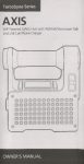
7. Do not place this appliance on an unstable cart, stand, or table. The
appliance may fall, causing serious injury to a child or adult, and serious
PORTABLE CART WARNING
damage to the appliance.
(symbol provided by RETAC)
Use only with a cart or stand recommended by the manufacturer, or sold with
the appliance.
Wall or shelf mounting should follow the manufacturer instructions, and
should use a mounting kit approved by the manufacturer.
An appliance and cart combination should be moved with care. Quick stops,
excessive force, and uneven surfaces may cause the appliance and cart
combination to overturn.
8. Slots and openings in the cabinet and the back or bottom are provided for
ventilation, and to insure reliable operation of the appliance and to protect it
from overheating, these openings must not be blocked or covered. The
S3125A
openings should never be blocked by placing the appliance on a bed, sofa,
rug, or other similar surface. This appliance should not be placed in a built-in
installation such as a bookcase unless proper ventilation is provided.
9. This appliance should be operated only from the type of power source indicated on the marking label. If you are
not sure of the type of power supplied to your home, consult your dealer or local power company. For appliance
designed to operate from battery power, refer to the operating instructions.
10. This appliance system is equipped with a 3-wire grounding type plug (a plug having a third (grounding) pin).
This plug will only fit into a grounding-type power outlet. This is a safety feature. If you are unable to insert the plug
into the outlet, contact your electrician to replace obsolete outlet. Do not defeat the safety purpose of the
grounding plug.
11. For added protection for this product during a lightning storm, or when it is left unattended and unused for long
periods of time, unplug it from the wall outlet and disconnect the antenna or cable system. This will prevent
damage to the product due to lightning and power-line surges.
12. Do not allow anything to rest on the power cord. Do not locate this appliance where the cord will be abused by
persons walking on it.
13. Follow all warnings and instructions marked on the appliance.
14. Do not overload wall outlets and extension cords as this can result in fire or electric shock.
15. Never push objects of any kind into this appliance through cabinet slots as they may touch dangerous voltage
points or short out parts that could result in a fire or electric shock. Never spill liquid of any kind on the appliance.
16. Do not attempt to service this appliance yourself as opening or removing covers may touch dangerous voltage
or other hazards. Refer all servicing to qualified service personnel.
17. Unplug this appliance from the wall outlet and refer servicing to qualified service personnel under the following
conditions:
a. When the power cord or plug is damaged or frayed.
b. If liquid has been spilled into the appliance.
c. If the appliance has been exposed to rain or water.
d. If the appliance does not operate normally by following the operating instructions. Adjust only those controls that
are covered by the operating instructions as improper adjustment of other controls may result in damage and will
often require extensive work by a qualified technician to restore the appliance to normal operation.
e. If the appliance has been dropped or the cabinet has been damaged.
f . When the appliance exhibits a distinct change in performance this indicates a need for service.
18. When replacement parts are required, be sure the service technician has used replacement parts specified by
the manufacturer that have the same characteristics as the original part. Unauthorized substitutions may result in
fire, electric shock, or other hazards.
19. Upon completion of any service or repairs to this appliance, ask the service technician to perform routine
safety checks to determine that the appliance is in safe operating condition.
-- 6 --
JVC VR-616
SAFETY PRECAUTIONS (VR-616U)
CAUTION
ATTENTION
RISK OF ELECTRIC SHOCK
DO NOT OPEN
RISQUE D’ELECTROCUTION
NE PAS OUVRIR
ATTENTION: POUR EVITER TOUT RISQUE D’ELECTROCUTION
NE PAS OUVRIR LE BOITER.
ACUCUNE PIECE INTERIEURE N’EST
A REGLER PAR L’UTIUSATEUR.
SE REFERER A UN AGENT QUALIFIE IN CAS DE PROBLEME.
CAUTION: TO REDUCE THE ELECTRICK SHOCK.
DO NOT REMOVE COVER (OR BACK).
NO USER SERVICEABLE PARTS INSIDE.
REFER SERVICING TO QUALIFIED SERVICE PERSONNEL
The lightening flash with arrowhead symbol,
within an equilateral triangle, is intended to
alert the user to the presence of
uninsulated “dangerous voltage” within the
product’s enclosure that may be of
sufficient magnitude to constitute a risk of
electric shock to persons.
Le symbole de l’ éclair a l’ interieur d’ un
triangle equilateral est destine a alerter l’
utilisateur sur la presence d’ une tension
dangereuse non isolee dans le boitier
duprodult. Cette tension est sufflsante pour
provoquer l’ electrocution de personnes
Le point d’ exclamation a l’linterieur d’ un
triangle equilateral est destine a alerter l’
utilisateur sur la presence d’ openations d’
entretien importantes au sujet desquelles des
renseignements se trouvent dand le manuel d’
instructions.
Ces symbols ne sont utilizes qu’aux Etats-Unis.
The exclamation point within an equilateral
triangle is intended to alert the user to the
presence of important operating and
maintenance (servicing) instructions in the
literature accompanying the appliance.
POWER SYSTEM
Connection to the mains supply
This unit should be used with 120V AC only.
CAUTION:
To prevent electric shocks and fire hazards, DO NOT
use any other power.
NOTE:
The rating plate (serial number plate) is on the top of
the unit.
This Class A digital apparatus complies with
Canadian ICES-003.
INFORMATION
This equipment has been tested and found to comply
with the limits for a Class A digital device, pursuant
to Part 15 of the FCC Rules.
These limits are designed to provide reasonable
protection against harmful interference when the
equipment is operated in a commercial environment.
This equipment generates, uses, and can radiate
radio frequency energy and, if not installed and used
in accordance with the instruction manual, may
cause harmful interference to radio communications.
Operation of this equipment in a residential area is
likely to cause harmful interference in which case the
user will be required to correct the interference at his
own expense.
-- 7 --
SYSTEME D’ALIMENTATION
Raccordement à la principale source d’alimentation
Ce magnetoscope ne doit etre utilize que sur du
courant alternatif en 120V.
ATTENTION:
Afin d’eviter tout resque d’incendie ou d’electrocution,
ne pas utiliser d’aufres sources d’alimentation
electrique.
REMARQUE:
La plaque d’identification (numero de serie) se trouve
dur le dessus de l’appareil.
Cet appareil numérique de la Class A est conforme à
la norme NMB-003 du Canada.
CAUTION
CHANGES OR MODIFICATIONS NOT APPROVED
BY JVC COULD VOID USER’S AUTHORITY TO
OPERATE THE EQUIPMENT.
JVC VR-616
SAFETY PRECAUTIONS(VR-616E)
POWER SYSTEM
Connection to the mains supply
This unit operates on voltage of 220 V to 240 V AC,
50 Hz/60 Hz.
Note:
The rating plate and the safety caution are on the top
of the unit.
WARNING
This is a Class A product. In a domestic environment
this product may cause radio interference in which
case the user may be required to take adequate
measures.
Warning Notice
FOR YOUR SAFETY (Australia)
1.Insert this plug only into effectively earthed threepin
power outlet.
2.If any doubt exists regarding the earthing, consult a
qualified electrician.
3.Extension cord, if used, must be three-core
correctly wired.
IMPORTANT (In the United Kingdom)
Mains Supply (AC 230 V)
WARNING – THIS APPARATUS
MUST BE EARTHED
The wires in this mains lead are coloured in
accordance with the following code;
GREEN-and-YELLOW : EARTH
BLUE : NEUTRAL
BROWN : LIVE
As the colours of the wires in the mains lead of this
apparatus may not correspond with the coloured
markings identifying the terminals in your plug,
proceed as follows.
The wire which is coloured GREEN-AND-YELLOW
must be connected to the terminal in the plug which is
marked with the letter E or by the safety earth symbol
or coloured GREEN or GREEN-AND-YELLOW.
The wire which is coloured BLUE must be connected
to the terminal which is marked with the letter N or
which is coloured BLACK. The wire which is coloured
BROWN must be connected to the terminal which is
marked with the letter L or coloured RED.
Caution for AC Power Cord
FOR YOUR SAFETY PLEASE READ THE FOLLOWING TEXT CAREFULLY.
Appropriate AC Power Cord must be used in each local area.
FOR CONTINENTAL EUROPE, ETC.
Not to be used in the U.K.
FOR U.K. ONLY
If the plug supplied is not suitable for your socket
outlet, it should be cut off and appropriate one
fitted.
-- 8 --
JVC VR-616
SAFETY PRECAUTIONS(VR-616U/E)
WARNING:
TO REDUCE THE RISK OF FIRE OR ELECTRIC
SHOCK, DO NOT EXPOSE THIS APPLIANCE
TO RAIN OR MOISTURE.
CAUTION
To prevent electric shock, do not open the cabinet.
No user serviceable parts inside. Refer servicing to
qualified service personnel.
The OPERATE button does not completely shut off
mains power from the unit, but switches operating
current on and off.
●Place of storage and use
Please avoid storing or using this DVR in the following
places:
• Extremely hot or cold places beyond the allowable
temperature for operation
(5°C (41゜F) - 40°C (104゜F) ).
• Humid or dry places beyond the allowable humidity
range
for operation (30 % - 80 % RH).
• Dusty or sandy places.
• Places exposed to oil, smoke or steam, such as the
kitchen vicinity.
• Vibrating or unstable places.
• Places prone to condensation.
• Places that generates strong magnetic fields, e.g.,
transformer or motor.
• Places near devices that generate electric waves,
e.g., transceiver or mobile phone.
• Places that generate radiation, X-rays or corrosive
gases.
●Handling the unit
• Please do not place heavy objects on the DVR, like a
monitor or TV.
• Please do not block the ventilation openings.
• Avoid violent shocks to the unit. Do not drop the unit.
• Do not stack up the equipment to prevent
temperature within from rising.
• Do not stand this equipment vertically during use.
• Handle this equipment with care. Do not subject it
to physical shock.
• Do not insert foreign object into this unit as this
may cause malfunction or electric shock.
• Please keep the mobile rack into the compartment.
As injury may result from fingers getting clamped.
-- 11 --
• Maintaining the unit (Please turn off the power
before performing maintenance work.)
Please wipe the unit with a soft cloth. Do not wipe it with
thinner or benzene lest the surface melts or becomes
dull.
For stubborn stains, wipe first with a water-dilluted
neutral detergent and then wipe dry.
• Please use the supplied power cord. Using a different
type or damaged cord may cause fire or electric shock.
• To save energy, be sure to turn off the system when
not in use.
• Do not use the power cord supplied with this
equipment on other devices.
• Batteries (remote controller)
• Please use AAA batteries.
• Please use 2 new batteries. (Do not mix new and old
batteries.)
• Please load the batteries correctly according to the +
and - signs.
• Please read the precautions printed on the batteries.
• If leaked battery fluid gets in eyes, rinse with clean
water and consult a doctor.
• If fluid leaks from the battery, please wipe the battery
compartment thoroughly.
• If the fluid comes into contact with your body, please
rinse the affected parts with water thoroughly.
JVC VR-616
PRECAUTIONS
WARNING
It should be noted that it may be unlawful to re-record
pre-recorded tapes, records, or discs without the
consent of the owner of copyright in the sound or
video recording, broadcast, or cable programme and
in any literary, dramatic, musical or artistic work
embodied therein.
• Hard-disk
The hard-disk is a consumable item. Replacement is
recommended after 10000 hours of use (if used in a
25°C environment). For information on maintenance
planning and costs, consult your nearest JVC dealer.
•Handling of the Hard-disk
Please do not extract the removable Hard-disk
or do not move this equipment for 15 seconds
after OPERATE OFF. It may cause a failure of
the Hard-disk.
• Do not expose the equipment to physical shock
during transport. In particular, do not move the
equipment during recording or playback.
• Please note that we will not provide compensation
for any failure during recording or playback due to
defects in this equipment or the hard disk drive.
• TV broadcast or other video (audio) recordings are
for personal use only. Unauthorized use of these
materials is strictly prohibited.
• Please note that recorded images will be erased
when replacing hard disks or upgrading firmware.
• To make back-up with CD-RW etc is strongly
recommended if the important data seems to be
recorded.
* All Product names stated in this manual are
trademarks or registered trademarks of their
respective companies. Marks such as ©, ® are
omitted in this manual.
-- 16 --
JVC VR-616
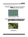
2. Part Names and Features
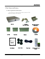
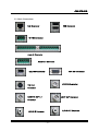
2.1 Basic Organization of DVR System
: In this Instructions, Digital Video Recorder is written as "DVR".
Contents and shape can be different.
Lock Key
Hard Rack Screw
VR-616
RS-485
Alarm Out
User Manual
Alarm In
Rubber Foot
-- 17 --
Power Cord
Rack Mount Bracket
Rack Handle
CD-ROM
Remote Control Unit
Battery
JVC VR-616
2.2 Features
1) High quality digital recording
Output and playback High-Resolution digital recording by using Wavelet compression.
2) Simple operation
Simple operation by jog /shuttle.
3) Simple setting
Enables simple installation and operation with basic setting and camera inputs.
4) Remote data back up
It is possible to back up and playback by using client program via network.
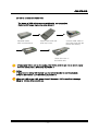
5) Backup (IEEE1394, USB)
Video images may be backed up to a compatible IEEE 1394 device such as an external HDD
or CD-RW device. In particular it is possible to extend HDD up to 4 pieces. It is also possible to
back up still images by using USB FDD or USB memory via USB port.
6) Multi screen monitoring function
Many multi screen monitoring modes are available such as 1/4/6/8/9/13/16 /user/ZOOM
screen.
7) Remote control/ view
Cameras can be remotely controlled and images can be viewed from anywhere through a
web browser over a private line or via the Internet without any special software.
If the HDD set to "Backup", you will not be able to use playback (P/B) remote security
function.( Live monitoring is possible through a web browser )
8) Audio Recording and Playback
One channel of audio may be selected for recording and playback with a video channel.
9) Diverse image backup function
Massive amounts of video can be stored in an internal HDD, removable HDD or
external IEEE1394 HDD.
10) Motion detection and Alarm recording function
Detects optional field, sensitivity, and sensing speed of each channel, and able to record
automatic register by connection with an outside sensor.
11) Alarm and Search Functions
Recorded images can be searched using search functions based upon time, date, alarm and
motion detection functions.
12) In/output contact point control
Able to add In/Output Alarms via connection to a contact point In/Output
terminal.
13) Recording and set-up options
All aspects of recording may be selected such as recording channel, fields per second,
image resolution and covert channel recording.
14) Diverse recording functions
Recording is possible by Manual, Alarm, and Schedule modes.
-- 18 --
JVC VR-616
15) Automatic check and recovery function
The system is designed for continuous, fault-free operation with built-in, self-monitoring
functions that monitor each component of the system and will automatically restart into
the previous mode if a system failure is encountered.
16) Camera control of popular dome models
Able to control a multitude of external cameras through the RS-485 port.
-- 19 --
JVC VR-616
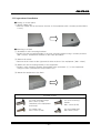
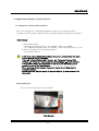
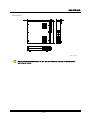
2.3 Preparation of installation
■ Putting on a level place
(1) Attach rubber feet.
- Attach 4 rubber feet in the bottom surface of the equipment with 4 screws provided (M3 x
11mm).
■ Mounting to a Rack
(1) Assemble 2 rack-mounting brackets
- Fasten the rack-mounting handle to the rack-mounting angles using 2 screws provided
(M4 x 10mm). Assemble 2 brackets in the same procedure.
(2) Remove 8 screws
- Remove the 8 screws at the right and left side surface of the equipment. (M4 x 12mm).
(3) Mount the rack-mounting bracket to the equipment
- Fasten 2 rack-mounting bracket (Assembled in the procedure (1) ) to the equipment
using 8 screws ( Removed in the procedure (2) ).
(4) Mount the equipment to the Rack
Provided screws
For rack-mounting angle
M4 x 12mm (4 EA)
(attached to the equipment
previously)
For rack-mounting
handle
M4 x 10mm (4 EA)
For rubber feet
M3 x 11mm (4 EA)
For removable HDD
M3 x 8mm (4 EA)
-- 20 --
JVC VR-616
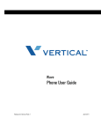
2.4 Part Names and Description
• Front
①
⑧⑨⑩
⑫
⑬
②
④
⑪
③
⑦
⑤
⑥
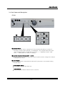
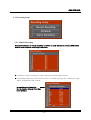
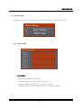
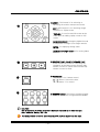
① Operate Switch
: Operate ON/OFF switch. Operate on/off by pressing this button for about 5
seconds. During system starting, it is displayed "16 CH Digital Video Recorder"
and "Preparing system. Please wait a moment." -> " Waiting to detect 1394
HDD...". Please wait for a while to starting.
② Channel Selection Buttons (CH1 – CH16)
: These buttons are used to select the screen monitors and to change the channel
settings at the menu.
③ AUTO Button
: The input channel is automatically switched in proportion to the speed setting
at the menu.
ALARM RESET Button
: This button is to stop the alarm out.
◀ (left) Button
: Menu Navigation Button. Moves cursor to the left.
-- 21 --
JVC VR-616
④ IMAGE SEQUENCE Button
: This button is for replay PB screen to IMAGE SEQUENCE mode.
▲ (up) Button
: Menu Navigation Button. Moves cursor up.
⑤ ZOOM Button
: This is used to zoom a freeze-frame in live or playback mode. Selected screen is X2.
ENTER Button
: This is for selecting set-up Menu.
⑥ TRIPLEX Button
: This button is for replay PB screen to TRIPLEX mode.
▼ (down) Button
: Menu Navigation Button. Moves cursor down.
⑦ Freeze Button
: This button is for seeing monitoring and PB screen as pause screen.
Freeze image backup button
: It is for backup freeze image at external FDD or USB memory.
▶ (right) Button
: Menu Navigation Button. Moves cursor to the right.
⑧ Display Button
: This button is for selection of the various on screen display options available.
⑨ USER Button
: This is for user’s screen mode. You can select one split display out of 8 screen then
you can organize the screen to your personal preference.
⑩ MENU Button
: The menu button allows scrolling through the available on screen menu.
⑪ REC, STOP, Reverse Playback (EXIT), PLAY Button (ENTER)
REC : This is for recording.
STOP : This is for stop PB.
Reverse Playback (EXIT) : This is for reverse PB. It is also for finishing menu setup,
moving to previous menu or erase wrong character.
PLAY Button (ENTER) : This is for playback and set-up menu.
⑫ Jog Shuttle (REV, CUE, Up, Down)
: It is possible to ‘quick search’ during playback and also used to change the modes of
the menu.
Shuttle : This is for quick search when PB and it is used for change MENU.
JOG : This is for slow search when PB and it is used for moving MENU’ s cursor.
⑬ Backup HDD (Removable HDD)
: This is removable HDD and it is used for Backup or Main.
-- 22 --
JVC VR-616
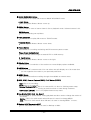
• Rear
① ② ③
⑤
④
⑥
⑦
⑩
⑨
⑧ ⑪ ⑫
⑭
⑮
⑬
① LAN : Enables screen search and control via Network. (Please use a category 5
cable with a shield.)
② USB Port 1,2 : For backup with external FDD or memory stick. It does not work
both USB1 & 2 at the same time. Please use one of them.
!
Please turn off the power when you connect external USB with DVR.
③ Spare : This terminal is not used.
④ RS-485 : For connecting with external Pan/Tilt camera. (Please use a twisted-pair
cable with a shield.)
⑤ ALARM IN : For alarm input. (Please use a shielded cable.)
ALARM OUT : For alarm output. (Please use a shielded cable.)
⑥ IEEE 1394 Port: Possible to extend storage space or backup by adding external
IEEE1394 or CDRW.
!
Please turn off the power when you connect external IEEE1394 with DVR.
! If you connect external HDD with external CDRW, impossible to recognize.
⑦ VGA OUT : Possible to connect with computer monitor. (CRT type)
Please set-up in Menu before use this connector.
⑧ Y/C OUT : Outputs contents of monitor output as a S-VIDEO signal.
⑨ MONITOR OUT 1,2 (Composite) : Menu appears at the time of menu setting and
displays when screen search or recording.
⑩ SPOT OUT (Composite) : Outputs video which is set-up from the menu.
⑪ MODE(PAL/NTSC) : Selects input video signal mode.
If you change PAL/NTSC, once it carries out operate-off. Operate-on is carried
out, and a message "Video mode was changed! " is displayed and it shows a
subsequent message. Select "O.K.", changes video signal mode.
When PAL/NTSC is changed, former record data is deleted!
An administrator password is reset when the PAL/NTSC mode is changed.
Please disable a password setting before changing the PAL/NTSC mode. When
PAL/NTSC mode is changed with a password setting enable, please use a
default password "1234".
⑫ AUDIO : I/O for audio recording/playback.
!
⑬ VIDEO IN BNC & THROUGH OUT (CH1 ∼ CH16)
: Inputs asynchronous video signal 1.0Vp-p.( 75 ohm )
: Loop out is changed to HI-Z automatically.
⑭ POWER Switch
: This is the main power switch.
⑮ AC INLET : For connecting with power cord.
-- 23 --
Digital Video Recorder
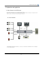
3. Explanation and Application
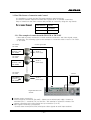
3.1 Basic Schematic of the DVR System
: This system can record up to 16 composite video signals.
Ability to check multiple screens during playback by using monitors & VGA units. It supports screen
search, monitor, and remote control through the Network.
3.1.1 Basic Schematic
NETWORK
Video signal of the input channel is 1.0 Vp-p on a 75Ω load. THROUGH OUT is changed
to Hi-Z Automatically.
-- 24 --
JVC VR-616
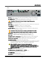
3.2 Basic Connections
LAN Connector
USB Connector
RS-485 Connector
Alarm IN Connector
Alarm OUT Connector
IEEE 1394 Connector
VGA OUT Connector
VIDEO IN Connector
Y/C OUT
Connector
MONITOR OUT 1,2
SPOT OUT Connector
Connector
AUDIO OUT Connector
AUDIO IN Connector
-- 25 --
JVC VR-616
3.3 Pan/Tilt Camera Connection and Control
It is possible to control the Pan/Tilt camera without special devices.
The Pan/Tilt camera supports RS-485 and is given an ID for parallel connection.
Easy to install from the menu screen and possible to control by using the Jog Shuttle.
Recommended Cameras:
Manufacturer
Model
JVC
TK-C676
JVC
TK-C655
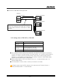
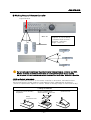
3.3.1 The example of connection with TK-C676 or TK-C655
Linked with a power connection, control terminal connection, and video signal output
connection. The following figure is the example of connection with 16 sets of TK-C676
or TK-C655.
TK-C676 or
TK-C655
Control signal cable
Coaxial cable
MACHINE ID : 1
Switch 8 : OFF
(RX TERM)
AC 24 V
power supply
TK-C676 or
TK-C655
MACHINE ID : 2
Switch 8 : OFF
(RX TERM)
AC 24 V
power supply
TK-C676 or
TK-C655
MACHINE ID : 16
Switch 8 : ON
(RX TERM)
Monitor
AC 24 V
power supply
Digital Video Recorder
VR-616
● Camera power connection.
● Control terminal connection (RS-485) : Please use a twisted-pair cable. Connect a
+terminal (TX+) / -terminal (TX-) to the RX+ / RX-terminal of a Pan/Tilt camera. The
camera connected at the end should set-up a terminus (110 Ω).
● Video signal connection (Composite)
: Checks video mode (NTSC/PAL) and inputs video signals at each input terminal.
-- 26 --
JVC VR-616
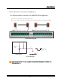
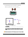
● Connection of RS-485 Control signal cable
VR-616
RS-485 Connector
Camera1 Connector
+
RX+
C
-
RX-
D
GND
Camera2 Connector
When you install in a place with many noises,
please use a twisted-pair cable with a shield.
A shield cable should be connected to a GND
terminal.
RX+
C
RX-
D
Camera16 Connector
RX+
C
RX-
D
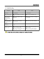
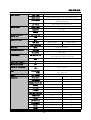
3.3.2 Setting values of TK-C676 or TK-C655
Item
Value
Switch 4
ON
Switch 5
ON
Switch 8
Terminal equipment is set to ON.
Other equipments are set to OFF.
ID
Install ID value independently.
● The functions can be used by this equipment are PAN/TILTE/ZOOM/FOCUS/AUTO
FOCUS. (A setup of a home position, a preset position, etc. cannot be performed) In
addition, in order to perform a home position setup and a camera image setup in
advance, it is possible to use and set-up by remote controler of RM-P2580 grade.
Please read the Instructions of RM-P2580.
● About setting values of VR-616, please refer to 5.1.2 Camera details and 5.1.3
Pan/Tilt Model Select.
● For information of other model, consult your nearest JVC dealer.
!
Please connect the Pan/Tilt camera of the same protocol (Camera Setup ->
Pan/Tilt Model Select -> Select Model).
-- 27 --
JVC VR-616
3.4 External Product Connections and Applications
3.4.1 External Product Connection of ALARM INPUT and Application
There are 16 alarm jacks for external devices.
Able to set-up REC ON/ OFF and Digital out motion according to ALARM IN signals.
GND 1 2 3 4 5 6 7 8
GND 9 10 11 12 13 14 15 16
Connection Diagram
5V
5V
ALARM IN
SW
1
3
DC
GND
Internal Circuit
Common GND
Circuit Diagram
!
Each External device which is connected with ALARM IN should be connected with
GND and Alarm In.
-- 28 --
JVC VR-616
3.4.2 External Product Connection of ALARM OUT and Application
Supports up to 4 separate alarms for motion control or alarms.
Possible to install output-events to each out terminal from the menu.
GND 1
2
3
4
+
Connection Diagram
Alarm Output
DC
POWER
Common GND
Inside DVR Circuit
Circuit Diagram
OUTPUT EVENTS
Digital inputs to alarm 1~ 16, Disk Full, Video Loss, Power Off, Admin. PW Chang
ed, Motion Detect.
Alarm-out outputs, and open collector state continuously until the alarm is reset.
When connecting to an external device, it is better to connect with the interface
circuit.
!
Maximum output current is 0.1A. Damage may occur if output is higher!
-- 29 --
JVC VR-616
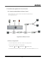
3.5 Installation and Application for Network Interface
3.5.1 Connection and Installation for Remote Control
Supports Web server, remote control, and remote file transfer due to
10/100mega Ethernet I/F.
Organization of Remote Control
3.5.2 How to Setup Static IP
1) Connect Network line, which has a fixed IP, by using the hub.
2) set-up system network at the Setup Menu.
Main Menu
System
Administration
Network Setup
3) Link web browser which supports JAVA Applets. ( MS Internet Explorer 6.0, etc. )
-- 30 --
JVC VR-616
3.5.3 Network Setup
IP Address
:
____.____.____.____
Subnet Mask
:
____.____.____.____
Gateway
:
____.____.____.____
DNS
:
____.____.____.____
Web Server Port Number : ___
We highly recommend you consult the Network Manager.
!
Note
● IP Address : This is the name of the product in TCP/IP.
You can use any IP in one Network.
If you want to link with the Internet, you need an Global IP address to avoid conflict.
● Subnet Mask : It is 32 Bit in length. ( = Address Mask )
● Gateway : This is used for connecting to the Network, which has a different structure
and Protocol.
● DNS : It is a link system for easy connection to the Internet.
For example, you can use an alphabetic address, e.g. www.company.com instead of a
number address.
● We highly recommend you consult the Network Manager.
● Web Server Port Number : This is for connecting external computer from Web Server.
In case of WWW using http, it is used 80 generally.
-- 31 --
JVC VR-616
3.6 Application of Remote Control Software
3.6.1 Using the "remote control software"
This is for viewing live or searching playback screens from a remote location.
[ Quality of the live screen depends on the recording quality and Network condition.]
How to Setup
1) Start Web browser.
( We highly recommend CPU : over 500MHz, RAM : over 64MB,
OS : Windows 98/ Me/ 2000/ XP, Browser : over Internet Explorer 5.5/ 6.0 )
2) Enter IP number in the homepage address.
( Use Domain name )
!
・If the icons are not displayed as change the screen, please check the menu
bar on the web site as followings.
Tools
Internet Options
General
Temporary Internet Files
Settings
Check for newer versions of stored pages
Automatically
・If Record/Web Select is not selected on the menu, live monitoring is not
possible to see on the Web Browser.
・When selecting divided screen, the screen display should delay due to
network condition.
・Please set to the "on-line" mode of Internet Explorer. It does not work "offline mode".
3.6.2 Web Browser
This is for wire internet by using computer.
Web Browser
-- 32 --
JVC VR-616
3.6.3 Live Screen Search
This is for searching 1, 4, 9 or 16 channels simultaneously from a remote location.
It is possible to control the Pan/Tilt camera, which allows to set-up the position of the
Pan/Tilt camera from a remote location.
► Pan/Tilt control : Possible to PAN, TILT and ZOOM by clicking the button on the web
screen.
3.6.4 Playback Screen Search
This is for searching playback screens. It is possible to check date and time.
-- 33 --
JVC VR-616
! Note
●
●
●
●
●
!
Remote monitoring is limited to 6 persons for assurance of the reliability of the system.
Only one person is allowed to see the web playback screen.
Possible to restrict remote user by password.
Possible to delay because of system status.
The reliability of remote monitoring is subject to the reliability of the Internet connection.
( Try rebooting in case of Internet malfunctioning. )
Notice
If the product is being backed up by HDD in use, you will not be able to use the remote
control function.( but live monitoring is possible. )
● HDD content for backup can not be replayed from remote software.
3.6.5 Client Software
The Client Software is at an attached CD-ROM, and if use this instead of the web browser,
more highly efficient operation can be performed. This software has the following
functions.
- Live Mode
- Search Mode
- Player Mode
- PTZ camera control
- Download (Back-up) Mode
- Support converting to AVI format to play with Windows Media Player
* Installer/ Menu/ buttons are written in English.
● CD-ROM Content
Following files and folder are in CD-ROM.
(1)"VR-616 ClientSW" Folder
Client software. As double click "setup.exe" as start installation.
(2)"VR-616 ClientSW Manual(Japanese).pdf"
Instructions of this software. (Japanese)
(3)"VR-616 ClientSW Manual(English).pdf"
Instructions of this software. (English)
● Operating Environment
System Requirements
PC
Compatible OS
Type
PC/AT compatible machine
CPU
Pentium III 500MHz and more
Memory
64MB and more
HDD
Free space 12MB and more
Windows 98/ 2000/ Me/ XP
-- 34 --
JVC VR-616
4. Function Explanation and Menu Setting
This system can set-up the motion conditions of the camera, recording conditions,
alarms, audio, and system settings from the monitor menu.
4.1 Front Button Explanation
4.1.1 Before Use
Make sure all the devices are properly connected as described in Chapter 2, then
connect to the power source.
!
When you turn on/off the power, please use power switch on the front.
HDD can be damaged as you use main power switch on the rear.
4.1.2 Monitor Out
This product can simultaneously record while live monitoring. You can select a
screen form by using the DISPLAY / USER button and INPUT button.
● It displays the selected channel on the monitor by pressing the INPUT button during
live or playback. It is used for selecting INPUT_CH at the MENU.
● Selected monitor configuration is displayed on the monitor “USER” button is for
screen configuration, which is set-up from the menu. 1,4,9,16,6,7,10 screen is
displayed as pressing the DISPLAY button during live. 1,4,9,16 screen is displayed as
pressing the DISPLAY button during playback.
-- 35 --
JVC VR-616
● Alarm Reset button is for stopping the external alarm motion.
● AUTO Button is ON/OFF. As pressing this buttons, the divided screen is
switched automatically.
4.1.3 REC
● By pressing this button, recording starts. The REC LED is on while
recording. As pressing this button again, recording is stopped. The REC
LED blinks during the Alarm record.
4.1.4 PLAY
● Press this button to select playback condition. Play LED is on while
playing. ( Refer to play mode for more details. )
● DISPLAY : It displays multi-screen when its’ monitoring or playback.
As pressing this button repeatedly when its’ monitoring, divided
screen is displayed 1/4/9/16/6/7/10 and as pressing this button
repeatedly when its’ playback, divided screen is displayed
1/4/9/16.
● IMAGE SEQUENCE : One playback screen is displayed with time slice on
4/ 9/ 16 divided screen.
● ZOOM : It can be X2 zoomed at any mode.
Possible to zoom status by using X (
) axis , Y (
) axis
and it is possible to move by using direction button in zoom status.
● TRIPLEX : This is overlay screen. Background screen is monitoring screen
and overlay screen is playback screen.
PB screen and Triplex screen will be displayed repeatedly as
pressing Triplex button while it is replaying.
-- 36 --
JVC VR-616
SHUTTLE
● JOG & SHUTTLE can search by frame in play mode by
using JOG when it is paused ( ll ) and possible to quick
search by an angle of the shuttle.
● At the menu setting, it is possible to move the position or
change the value by using JOG .
● Slow playback can be performed by using JOG during
playback/Reverse playback. It takes a time for a while,
from a SLOW onscreen display "| | | | ► " appear and
then a SLOW PLAYBACK image starts. When you press
twice the PLAY/Reverse Playback button under shifting,
the image changes immediately.
JOG
● When the DVR is in PLAY MODE, the buttons have the
functions indicated above button mark. (REC, stop ( ■ )
/ pause( ll ) / reverse play (◄ )/ pause ( ll )/ play (►))
● When the DVR is in menu mode, the buttons have the
functions indicated below. (EXIT, ENTER)
!
In the play mode if you press the Enter button the DVR will be paused, then you
can search field by field using the jog/shuttle control. You can search quickly
using the Shuttle and slowly by using the Jog.
4.1.5 Menu Setup
● You can easily change the Camera Setup, Recording Setup,
and Audio Setup by the graphical user interface screen.
If you press the menu button, you can see the next menu screen. It
can be moved up and down by using Jog. The Menu is selected by
clicking the ENTER button.
Setup value (symbols, Alphabet Upper case (Capital) letters, lower
case letters, numbers and position) of the menu can be changed by
using X & Y axis /EXIT/ENTER buttons, and INPUT button.
4.1.6 FREEZE
● By pressing the freeze button then pressing the channel buttons(1~16),
the selected screen will display a still image.
-- 37 --
JVC VR-616
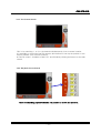
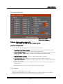
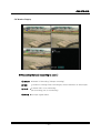
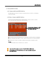
4.1.7 Explanation of Image Sequence and Triplex
● IMAGE SEQUENCE : One playback channel is replayed to the divided screen field by field
in sequence.
Press the display button to select the type of display division.
Image Sequence Playback Screen of 16 Channel
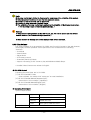
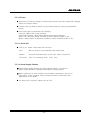
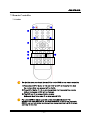
● TRIPLEX : This is an overlay (picture in picture) screen. You can monitor live screen and
playback screen at the same time. It is returned to playback screen as pressing
the PLAY button (ENTER button) after setup monitoring channel you want to
see. If you want to change playback screen, press the Channel Selection
buttons.
TRIPLEX Playback Screen
-- 38 --
JVC VR-616
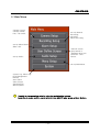
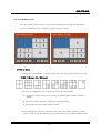
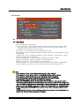
5. Main Menu
Camera Control,
Camera Details,
Pan / Tilt model.
set-up Manual
Recording,
Schedule,
Alarm Recording.
set-up Alarm Name,
Alarm Link.
Select 8 screen
group which is
displayed when you
press the “User”
button.
set-up Audio.
set-up Main Menu.
System Log, Alarm Log,
HDD Management
Backup
Auto Select
Video Output
Administration
About System.
!
Possible to change setting value by using Jog and direction buttons.
According to cursor position, cursor should move right/left when press up/down buttons.
-- 39 --
JVC VR-616
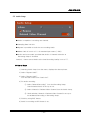
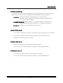
5.1 Camera Setup
It is possible to set-up image which will connect at input port and able to set-up Pan/Tilt
camera which will connect with RS-485.
5.1.1 Camera Control
Make sure all of the Pan/Tilt cameras are the same manufacturer.
Use the cameras which are supported by the same protocol.
1) RS-485 enables long distance transfer.
2) Possible to connect in parallel.
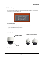
5.1.1.1 Pan/Tilt Camera
Camera ID Setup
Examples of Camera Rotation
Pan
Camera
Pan/Tilt Camera
-- 40 --
Tilt
JVC VR-616
5.1.1.2 How to Use
1) Checks camera ID setup value from the camera setup menu.
2) Selects Pan/Tilt Control from the menu.
3) Selects motion by Jog or right/left button.
4) Moves shuttle left or right.
Checks whether camera ID and Pan/Tilt camera ID are the same installation if
the Pan/Tilt camera does not activate.
Also, checks whether the control line of the Pan/Tilt camera is in the correct
location.
5) Press the EXIT button to return to the Camera Setup Menu.
!
If you use multiple Pan/Tilt cameras, make sure all of the Pan/Tilt cameras are
the same manufacturer.
-- 41 --
JVC VR-616
5.1.2 Camera Details
Setup channel
● Installs Name, Camera ID (Pan/Tilt Camera), Model and Color (Brightness,
Contrast, Saturation, Hue) of each channel.
5.1.2.1 How to Setup
1) Checks the channel number as indicated at the bottom of the tab, and then
checks whether the background is the correct screen.
(The channel number can be changed by pressing the INPUT button.)
2) Selects contents which you want to change by jog.
3) Possible to change
ENTER button
EXIT button
◀ button
▶ button
Jog
setup status by using the buttons as follows.
: Change and complete selected contents.
: Make cancellation.
: Move to left at the Name.
: Move to right at the Name.
: Can change character and number by jog rotation.
4) To return to the preset menu, press the EXIT button.
5) If a Pan/Tilt camera is connected, test after setting-up the camera ID.
-- 42 --
JVC VR-616
5.1.2.2 Camera Name
● Name : Possible to create an alphanumeric nickname of up to 16 characters
(including symbols) as shown below.
You can see the next character repeatedly by using Jog.
Character Mark
Blank ! “ # $ % & ’ ( ) ” + , - . / 0 1 2 3 4 5 6 7 8 9 : ; < = > ?
@ABCDEFGHIJKLMNOPQRSTUVWXYZ
[\]^_’abcdefghIjklmnopqrstuvwxyz{|}~
How to Use
1) Selects Name by Jog.
2) Possible to write and amend if you press the ENTER button.
3) Writes and amends by using the RIGHT/LEFT button and Jog.
4) Complete by clicking the ENTER button.
!
It is NOT possible to display all the characters when the screen is divided into more than
6 pictures. In this case "…" is displayed.
5.1.2.3 Pan/Tilt Camera Setup
● Camera Setting : Camera ID, Reverse Pan, Reverse Tilt, Control Test
1) Camera ID : For controlling the Pan/Tilt camera.
Setting ID is for distinguish the Pan/Tilt camera, which is connected in parallel.
Camera ID uses 1~255 number.
( Be sure to check the specifications of the Pan/Tilt cameras. )
2) Reverse Pan, Reverse Tilt : It reverses a Pan/Tilt Camera direction.
Usually, the Pan/Tilt direction can be changed depending on the location
and mounting of the Pan/Tilt camera.
3) Control Test : Possible to test whether Pan/Tilt Camera setup is correct or not.
Useful when checking after setup finishes.
-- 43 --
JVC VR-616
5.1.2.4 Adjustment
● Possible to install each input video color ( Brightness, Contrast, Saturation ) value
as a number 0~100 and Hue can be installed as a number -128~127.
Please, install a proper value for a background checking screen.
● How to Setup
1) Move to the desired position by using Jog or up/down buttons.
2) If you press the ENTER button, the next image is displayed with video input.
3) Jog left or right (or press up/down buttons) for changing the number.
4) If you press either the ENTER or EXIT button, setup is finished. After
finishing setup, the previous screen is displayed.
Brightness : Controls brightness.
Contrast
: Controls contrast.
Saturation : Controls saturation.
Hue
: Controls hue.
-- 44 --
JVC VR-616
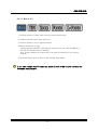
5.1.3 Pan/Tilt Model Select
None
JVC Camera
Pelco Camera
Selects one of Camera
driver.
* If you connect with TK-C676/TK-C655, please select "JVC CAMERA"
● How to Setup
1) Connect the Pan/Tilt camera to the RS-485 port.
2) Select the same drive, which is selected from the “Pan/Tilt Model Select”
menu.
3) Set-up the Camera ID at “Camera Setting”.
4) Test it by using Camera Control.
-- 45 --
JVC VR-616
● Selects baud rate for each camera. (Factory default is 9600 bps)
* If you connect with TK-C676/TK-C655, please select "9600 bps"
-- 46 --
JVC VR-616
5.2 Recording Setup
5.2.1 Manual Recording
Manual Recording is for setup recording condition of each channel as pressing REC button
when it is not recorded according to schedule.
● Possible to control recording for each channel as pressing REC buttons.
● As pressing Enter button after moving cursor to channel by using Jog, channel for setup
will be changed blue bar as blow.
In case Schedule Recording
Box is checked, Manual Recording
is not working.
-- 47 --
JVC VR-616
● Each symbol means as below.
!
·
·
·
·
In case Schedule Recording box is checked, recording is started according to
schedule regardless of Manual Recording. For using Manual Recording, do not check
Schedule Recording box.
● : Always Recording.
A : Alarm Recording.
M : Motion Recording.
fps/fps : The former ‘fps’ is field rate of Always Recording,
the latter ‘fps’ is filed rate of Alarm Recording/Motion Recording.
● From the Manual Recording menu, press the Enter button then the below picture
(Recording Events) will display.
5.2.1.1 Recording Events
● As press the ENTER button at the selected block, possible to set up Recording Events of
block like above picture.
● Always : Records always if it is in Recording Time
Motion : Recording is started if motion is detected which is in set up screen of Channel
Alarm : Records when the selected alarm is received.
!
Please do not set-up a channel without video input as record. Please take out all
checks, Always, alarm, and motion.
5.2.1.2 Quality
● As press the ENTER button on the left-side of the QA line, possible to set up Recording
Quality like above picture.
● Setup range : 1 ~ 7. (Default setting : 5)
(1=Low, 7=the Highest.)
● When you place the bar on the right-hand side of the "QA" line and press the Enter button,
you will be able to select Audio Recording On and Audio Recording off as below.
-- 48 --
JVC VR-616
5.2.2 Schedule
● Schedules recording by date, time and channels.
● Schedules recording for specific day.
● If it changes from a menu, a clock mark is displayed on the screen lower right,
and it will be in the state of TIMER STANDBY or TIMER RECORD. VR-616
does not have a power-saving mode.
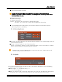
5.2.2.1 Explanation of Recording Schedule
1) Time
● The above numbers indicate the hour in the day. (00 ~ 23)
-- 49 --
JVC VR-616
2) Channel
● The left numbers indicate the input channel. (1 ~ 16)
3) Quality Level, Alarm Recording
● QL indicates quality level as recording.
● AR indicates whether Audio Recording or not.
4) Recording Events
● : Always Recording.
A : Alarm Recording.
M : Motion Recording.
● F/F=fps/fps : The first ‘fps’ means field rate of Always Recording, The second
‘fps’ means field rate of Alarm Recording/ Motion Recording.
Ex)
The left picture indicates it is being Always Recording
with recording 3fps.
The left picture indicates it is being Alarm, Motion
Recording with recording 4fps.
-- 50 --
JVC VR-616
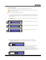
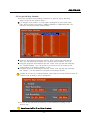
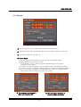
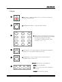
5.2.2.2 How to Setup
● Recording Schedule is set-up in block. Minimum block is an hour.
A time setting cannot be performed from the remote control unit. Please use
the front panel buttons.
!
● How to Setup Recording Schedule Block
1) As using left/right direction button, designates time block at the same channel.
As using up/down direction button or jog, designates channel block at the time
zone of 0 hour.
2) As pressing ‘DISPLAY’ button at the block to change, the following picture will
display in order.
00
01
02
03
04
05
● Appears yellow bar at the left of block.
00
01
02
03
04
05
● Appears yellow bar at the right of block.
00
01
02
03
04
05
● Disappears yellow bar at the block.
1
1
1
3) As pressing the left button in case yellow bar is at the left of the block :
The block extends for an hour and extended time is set-up as Recording
Schedule of present block.
00
01
02
03
04
05
1
When the yellow bar is located in the left side of the block and you press the
right arrow button, then the source configuration in the block will be
deleted (reduced) and the configuration in the deleted block will follow the
configuration in the left block. (But, if the current block is located in the most left
side, then the configuration of deleted block will follow the default setting.)
00
01
02
03
04
05
1
-- 51 --
JVC VR-616
● When the yellow bar is located in the right side of a specific block and you
press the left arrow button, then the source configuration of the block in the
right side of the current block will copied (expanded)
(But, if the current block is located in the most right side, then the configuration
of deleted block will follow the default setting.)
00
01
02
03
04
05
1
● When the yellow bar is located in the right side of a specific block and you
press the right arrow button, then the source configuration of the block in the
current block will be copied (expanded) to the right block.
00
01
02
03
04
05
1
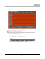
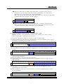
Ex.)Setup the schedule recording at 9:00 - 12:00 and 15:00 - 18:00.
(Attention In order to give explanation simply, all are displayed for 00:00- 24:00.
On an actual screen, it displays a part of them.)
(1) Press the Enter button when the cursor is on the schedule table.
(2) Select camera 1 by using JOG or up/down button. Press the display button, and a
yellow bar is displayed on the position at 00:00
00 01 02 03 04 05 06 07 08 09 10 11 12 13 14 15 16 17 18 19 20 21 22 23
1
(3) Press right button, and move it to the position of 09.
(4) Press display button and a yellow bar is displayed on the right-hand side of 23
(23:59).
00 01 02 03 04 05 06 07 08 09 10 11 12 13 14 15 16 17 18 19 20 21 22 23
1
(5) Press left button, and move it to the position of 12. Press display button, and a
yellow bar will disappear.
(6) Press right button, and move the specific block.
(7) Press display button, and a yellow bar will be displayed on the left-hand side of a
specific block.
00 01 02 03 04 05 06 07 08 09 10 11 12 13 14 15 16 17 18 19 20 21 22 23
1
(8) Once again, press a display button, and a yellow bar will be displayed on the
right-hand side of 23 (23:59).
(9) Press left button, and move it to the position of 15. Press display button, a yellow
bar will disappear.
00 01 02 03 04 05 06 07 08 09 10 11 12 13 14 15 16 17 18 19 20 21 22 23
1
-- 52 --
JVC VR-616
(10) Press right button, and move the specific block.
(11) Press display button, and a yellow bar will be displayed on the left-hand side of a
specific block.
00 01 02 03 04 05 06 07 08 09 10 11 12 13 14 15 16 17 18 19 20 21 22 23
1
(12) Once again, press display button, and a yellow bar will be displayed on the righthand side of 23 (23:59).
(13) Press left button, and move it to the position of 18. Press display button, and a
yellow bar will disappear.
00 01 02 03 04 05 06 07 08 09 10 11 12 13 14 15 16 17 18 19 20 21 22 23
1
(14) By the above procedure, schedule setup has completed. Moreover, this state
seems that one day is divided into five blocks. If a block is chosen with a right/left
button and an ENTER button is pressed at it, a record setup of each block can be
set-up freely. However, mind that a boundary line will disappear if an adjacent
block is set to the same setup.
● If press the ENTER button as block is selected, the below picture (Recording Events)
will be displayed then possible to set-up recording option for selected channel.
● The way of setup is the same with Manual Recording.
● After finish setup, press the EXIT button then it is returned to Manual Recording menu.
!
Please do not set-up a channel without video input as record. Please remove all
checks such as Always, Alarm, and Motion.
● As press the ENTER button at the QL, possible to set-up Recording Quality
like above picture.
● Set-up range : 1 ~ 7. (Default setting : 5)
(1=Low, 7=the Highest.)
● After finish setup QL and each channel, press the EXIT button for out of menu.
-- 53 --
JVC VR-616
5.2.2.3 Audio Recording
● When you place the bar in AR and press the “Enter” button, then you will be
able to select Audio Recording On and Audio Recording off as below.
● Audio Recording On
● Audio Recording Off
5.2.2.4 Setup Days of the Week
● You can select a day to configure the recording schedule using Enter button
and Jog dial.
5.2.2.5 Copy Schedule
● You can copy the recording schedule configuration of a specific day of the
week to other days of the week. After set-up the day of copy, press the Copy
button.
-- 54 --
JVC VR-616
5.2.2.6 Specific Day Schedule
● You can configure the recording schedule of a specific day by pressing
“Enter” button in the ‘Specific Days…’.
● If it changes from a menu, a clock mark is displayed on the screen lower
right, and it will be in the state of TIMER STANDBY or TIMER RECORD. VR616 does not have a power-saving mode.
● Using the left/right arrow buttons and the ‘Enter’ button and selecting the
‘Add’, you can add and configure new “Specific Day Schedule” up to 16.
● Using the up/down arrow buttons and the “Enter” and Jog dial and selecting
the “Disable/Enable”, you can decide if you will record it according to the
configuration of recording schedule, or not.
● Using the up/down arrow buttons and the “Enter” and Jog dial and selecting
the “Delete”, you can delete the configured recording schedule.
!
Please do not set-up a channel without video input as record. Please remove all
checks such as Always, Alarm, and Motion.
● You can set the start and the end time of the schedule recording for the
specific day.
!
Actual record will be till end time +1 minute.
-- 55 --
JVC VR-616
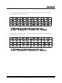
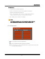
As each input channel is selected, the maximum recording Field/Sec can be changed
as in the below table. ( Only for NTSC )
1CH → 30F/S
2CH → 30F/S
3CH → 15F/S
4CH → 15F/S
5CH → 10F/S
6CH → 10F/S
7CH → 7F/S
8CH → 7F/S
9CH → 6F/S
10CH → 6F/S
11CH → 5F/S
12CH → 5F/S
13CH → 4F/S
14CH → 4F/S
15CH → 3F/S
16CH → 3F/S
It is NOT possible to be 60 field according to input channel number.
Ex) 16CH → 16*3=48(Field), 5CH → 5*10=50(Field), 1CH → 1*30=30(Field)
As each input channel is selected, the maximum recording Field/Sec is changed as in
the below table. ( Only for PAL )
1CH → 25F/S
2CH → 25F/S
3CH → 12F/S
4CH → 12F/S
5CH → 8F/S
6CH → 8F/S
7CH → 6F/S
8CH → 6F/S
9CH → 5F/S
10CH → 5F/S
11CH → 4F/S
12CH → 4F/S
13CH → 3F/S
14CH → 3F/S
15CH → 3F/S
16CH → 3F/S
It is NOT possible to be 50 field according to input channel number.
Ex) 16CH → 16*3=48(Field), 5CH → 5*8=40(Field), 1CH → 1*25=25(Field)
-- 56 --
JVC VR-616
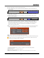
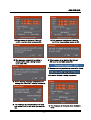
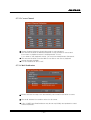
5.2.3 Alarm Recording
● Set-up recording time which is before event and after event when its’ Alarm/Motion
Events.
● The RECORD Indication LED and ONSCREEN display might be displayed 10 - 20
seconds longer than actual record time.
● set-up Alarm Input.(1-16)
!
If the record is started by alarm / motion detection from the stop mode (the
sensor record mode), audio does not record even though it is set to on.
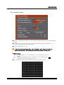
● Motion Setup
Full : Recording (REC) is started when motion is detected on the full
screen.
Area : REC is started when motion is detected on the selected grid. (
( this grid can be selected by the user. )
● set-up area as pressing the ENTER button at Area Define menu.
-- 57 --
)
JVC VR-616
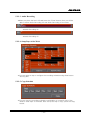
● How to Setup
ⓐ Jog direction of field setup.
Jog Direction
X-axis
Direction Button
Y-axis
Direction Button
ⓑ The user field setup is moved to the place by jogging. The first
location and the last location can be selected by clicking ENTER.
ⓒ Area field setup is moved to the place by jogging and can check the
field by using ENTER.
ⓓ After setup is finished, move to the higher level menu by clicking
EXIT.
● Sensitivity
Sensitivity refers to the sensitivity to motion. Sensing Speed is the speed of
motion. Possible to set-up a range from 1 to 10. (1=Low/Slow, 10=High/Fast.)
Motion must be clicked on Recording Events. After detecting motion by
Motion Area, Sensitivity and Sensing Speed, recording is started.
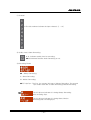
How to Setup
ⓐ Move to Sensitivity or Sensing Speed by using Jog then press the enter
button for setup value.
ⓑ After setup is finished, move to the previous menu by clicking EXIT.
!
!
Sensitivity is detected sensitive changing in proportion to value.
Sensing Speed is no reaction to fast changing because
renewal speed is slow down as increasing Sensing Speed value.
If a setup is completed, please be sure to check real operation.
When an area setting screen is opened during recording, even if there is no
motion in an image. Although the detection log may be recorded, the
Motion-Detection Recording does not work.
-- 58 --
JVC VR-616
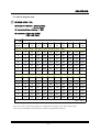
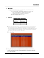
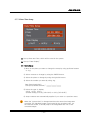
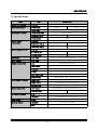
5.2.4 Recording Duration
!
● MODE : NTSC / PAL
● Maximum Field Rate : 60 F/S (NTSC)
: 50 F/S (PAL)
● Recording Channel Number : 16Ch
● Resolution : 720 * 240 (NTSC)
: 720 * 288 (PAL)
Field Rate
Quality
3F/
1S
2F/
1S
1F/
1S
1F/
2S
1F/
3S
1F/
4S
1F/
5S
1F/
6S
1F/
8S
1F/
16S
Record Condition HDD : 240 Gbyte, Audio Sampling Rate : 8KHz
7
31
46
93
187
280
374
468
561
748
1497
6
41
62
124
249
374
499
624
748
998
1997
5
52
78
156
312
468
624
780
936
1248
2496
4
52
78
156
312
468
624
780
936
1248
2496
3
62
93
187
374
561
748
936
1123
1497
2995
2
72
109
218
436
655
873
1092
1310
1747
3495
1
104
156
312
624
936
1248
1560
1872
2496
4993
Record Condition HDD : 240 Gbyte, Audio Sampling Rate : NONE
7
31
46
93
187
280
374
468
561
748
1497
6
41
62
124
249
374
499
624
748
998
1997
5
52
78
156
312
468
624
780
936
1248
2496
4
62
93
187
374
561
748
936
1123
1497
2995
3
72
109
218
436
655
873
1092
1310
1747
3495
2
83
124
249
499
748
998
1248
1497
1997
3994
1
104
156
312
624
936
1248
1560
1872
2496
4993
(Unit : Hour)
(You can control recording quality from Manual Recording of the Recording Setup.
This record timetable is indicated the minimum guaranteed values.)
-- 59 --
JVC VR-616
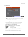
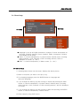
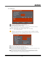
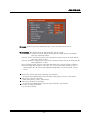
5.3 Alarm Setup
Alarm Setup is used for connecting with external devices such as alarm or buzzer.
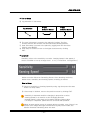
5.3.1. Alarm Name
How to Setup
a. Select alarm channel by using Jog.
b. Selects name by using play, right/left, and jog.
c. As jog is rotated from right to left, characters change.
Possible to write up to 16 alphanumeric and symbolic characters.
-- 60 --
JVC VR-616
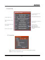
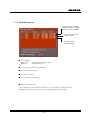
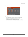
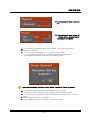
5.3.2 Alarm Link Setup
Alarm output number
Present output number is 1
● Events : Select condition of Alarm Out.
Alarm inputs are 16EA and Alarm outputs are 4EA.
● Alarm Link Explanation
The above menu will display as checking Alarm Link button.
1) Alarm (left of the above picture) : Sets up which alarm will be output when alarm
occurs. Inputs are 1~16 and possible to select repeatedly.
2) Events (above of right) : Sets up events which will be output alarm signal. There are
Disk Full, Admin, PW Changed, Video Loss, and Motion. Possible to select
repeatedly.
3) Alarm Off (below of right) : How to off alarm when alarm occurred.
There are Manual and Auto.
4) Alarm Output Number : The part for selecting output port when signal is in
according to alarm and event setup. Output ports are in rear of product and able to
select one of them.
5) Alarm in/out ports are in rear of product there are 16pcs of input ports and 4pcs of
output ports.
Move to previous menu after finish setup by using EXIT button.
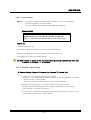
5.3.2.1 Alarm
Moves by using ▲, ▼ buttons or Jog.
Displays alarmed channel. For selecting channel you want to detect, press ENTER
button after moving cursor to detect. Canceling is the same way.
-- 61 --
JVC VR-616
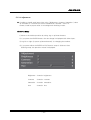
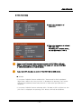
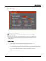
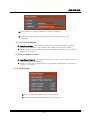
5.3.2.2 Events
● Alarm has occurred according to select events such as Disk Full, Admin PW. Changed
Video Loss, Motion Detect.
● Checks event you want to detect from the Events menu by using Jog and ENTER
button.
● Each event type is indicated by the following.
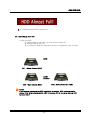
Disk Full : When HDD is fully recorded.
Admin.PW Changed : When Admin Password has been changed.
Video Loss : No video image. Possible to select channel number or ALL.
Motion : When motion is detected. Possible to select channel number or ALL.
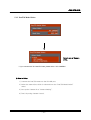
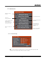
5.3.2.3 Alarm Off
● How to off “Alarm” when alarm has occurred
Auto
: Alarm is turned off automatically after setting time.
Manual
: As press the Alarm button on the front, alarm is turned off.
Time (Sec) : This is for selecting “Auto”. (Unit : Sec)
5.3.2.4 Alarm Output Number
● Select Alarm Output Number by using channel button.(1~4 buttons)
Alarm Output Number is changed according to pressing button.
● Alarm Output port is Open Collector and could be connected to rear port of
the product. It has 4 outputs. Refer to External Product Connections and
Application for the details.
● For Alarm OUT connector, please refer to P.29
-- 62 --
JVC VR-616
5.4 User Define Screen
User can organize the screen to your personal preference by using the user button.
It is very convenient if you use AUTO function at User Screen.
● How to Setup
1) Select one of 8 variations of multi-screen views by using left/right buttons or Jog.
(NTSC : 8 Screen, PAL : 8 Screen)
2) As color is changed to blue, change the screen by using Button.
ⓐ Change the screen, which color is blue, by selecting the Channel Selection
button.
ⓑ Move to another screen by using Jog/ up・down button.
ⓒ After finishing, select either ENTER or EXIT.
3) After setting end, finish the menu and then press the “USER” button of screen
button. User Screen will display as press the INPUT CH on USER SCREEN mode.
-- 63 --
JVC VR-616
5.5 Audio Setup
● Audio is capable of recording one channel.
● Sampling Rate is 8 KHz.
● Bypass is possible to Audio Out as recording Audio.
● Master Gain is from 0 to 5. 0 is standard input status. (-5db)
● Audio can be recorded, provided that Audio of Channel Selection at
Recording Setup is checked
Caution!! Cannot record Audio at the time Recording Quality is set to "7".
● How to Setup
1) Selecting Audio Setup from the menu, displays the above picture.
2) Select “Bypass Audio”.
3) Select “Bypass Audio”.
You can hear sound from “Audio Out”.
4) For audio recording
① Select “Manual Recording” from the Recording Setup.
Check whether Audio is set-up or not.
② Select Channel of Related Video Channel from the Audio Setup.
③ Check whether Channel of Related Video Channel is set-up or
not at Manual Recording of Recording Setup.
5) Finish by using EXIT button.
6) Audio is recording as REC button is on.
-- 64 --
JVC VR-616
5.6 Menu Setup
VR-616E
VR-616U
● Language is set-up at English and able to change to French and Spanish on
VR-616U. (English, German, French, Spanish, Italian, Portuguese, Chinese
are available on VR-616E)
● Status : It controls transparency of present status( channel name, recording
status indicator, clock, indicator of HDD recording amount ) which is
displayed on screen. (0 ~ 80%)
● Menu : It controls transparency of Menu screen. (0 ~ 80%)
● How to Setup
1) Selecting Menu Setup from the menu, displays the above picture.
2) Move to the place you want to set-up by Jog.
3) For changing language, press the ENTER button at Language and
select the language.
4) If you change the value by jog after moving to Status and pressing the Enter
button, it controls transparency of present status( channel name, recording
status indicator, clock, indicator of HDD recording amount ) which is displayed
on screen.
5) If you change the value by jog after moving to Menu and pressing the ENTER
button, it controls transparency of Menu screen.
6) Finish setup by using EXIT button.
-- 65 --
JVC VR-616
5.7 System Setup
You can check all of the
product motion.
Select Main/Backup HDD.
Checks Alarm Log.
Back up data by using
HDD.
set-up motion contents of
Auto button.
set-up Spot Output and
VGA Output.
Network Setup,
Date/Time Setup,
Admin Password,
Web Password, Update
Program
Check system version.
5.7.1 System Log
● Log records all actions which occurred on the system while operating.
● Easy to use by using Date or Filter.
-- 66 --
JVC VR-616
● How to Setup
1) Log records all actions which occurred on the system while operating.
2) You can check “Log” by the following :
① Set-up start date, which will be marked on the LOG, by Jog.
Select year/month/day by using the right/left button.
Change year/month/day number by using Jog.
② Select “Log Filter” for quick search.
③ Select “Display” button.
● Log Screen
Log screen contents are as follows:
Alarm In 1-16
Disk Full
Video Loss
Power On/Off
Network Access
Menu Setup
Motion Detect
● On the system log display screen, if you chose a log line by the vertical button or
JOG Dial and then press the ENTER button, playback the recorded image starts
from the time when the log was recorded. If there was no record image when a log
is recorded, playback the recorded image from the nearest position. As pressing a
stop button, it will return to a system log screen.
5.7.2. Alarm Log
● Alarm Log displays alarm recording which detects on system such as motion.
● On the alarm log display screen, if you chose a log line by the vertical button or
JOG Dial and then press the ENTER button, playback the recorded image starts
from the time when the log was recorded. As pressing a stop button, it will return
to an alarm log screen.
-- 67 --
JVC VR-616
5.7.3 HDD Management
The state of the 1st Builtin HDD. Capacity is 120GB,
and Free Space is 120GB
The state of the 2nd
Built-in HDD.
The state of the
removable HDD.
● set-up HDD
Main HDD : Can be used for basic REC.
Backup
: For backup HDD.
● set-up REC mode of the main HDD.
● set-up overwrite mode.
● Log clear function.
● set-up HDD using percent.
■ Clear All Previous Log
If you check here, and press EXIT button, "Do you want to Update Disk?" is
displayed. As pressing "Yes" button, Log information will be deleted.
-- 68 --
JVC VR-616
● HDD Information
● This is for information of
Local HDD.
● This is for information of external
IEEE 1394 HDD.
As clicking the "Indicate" button,
you can know which HDD is.
!
Please turn off the power when you connect external IEEE1394 or USB with
DVR for the purpose of avoiding damage. After power off, connect IEEE1394
or USB device and then turn on the power.
!
If you reset DVR, you have to power off the IEEE 1394 or USB device.
■ Initialize
・If you press "Initialize" button at Main HDD, "Data stored in HDDs numbered
larger than x will be lost. Are you sure?" is displayed. As pressing "Yes" button,
HDD will be initialized. Please note all HDD for main after specified HDD is
initialized.
・If you press "Initialize" button at backup HDD, "All data in HDD x will be lost. Are
you sure?" is displayed. As pressing "Yes" button, HDD will be initialized.
-- 69 --
JVC VR-616
● It is displayed when HDD is almost full.
● How to Setup New HDD
1) Add new HDD.
① When adding a new HDD, you must turn the power off.
② Backup HDD is only one.
③ It is better to clear the data when an HDD is registered for the first time.
MAIN
IDE1 : Master (Internal HDD)
MAIN/
BACKUP
IDE1 : Slave (Internal HDD)
!
IDE2 : Slave (Removable HDD)
Notice
If you make a mistake during HDD installation or removal, HDD contents can be
erased. ( Ex. When changing Main HDD to Backup HDD or changing Backup HDD
to Main HDD.)
-- 70 --
JVC VR-616
2) Overwrite Disk When Disk Full
Monitor screen displays a similar message as the following according
to overwrite on/off.
On
Main HDD is full, it starts to overwrite old DATA.
Off
When Main HDD is full (100%), recording is stopped.
3) Clear All Previous Log.
It is the place for initial Log content.
It is better to initiate Log, when HDD or DATA is changed.
!
To make back-up with CD-RW etc should be strongly recommended if the
important data seems to be recorded.
-- 71 --
JVC VR-616
5.7.4 Backup
● Record a portion of the main HDD content to a Backup HDD.
● Must have more than one Backup HDD and recording content of setup date.
● Possible to backup HDD and CD.
● How to Setup
1) Set-up start and end dates by using Jog and the right/left button.
2) Select Backup and backup will start.
It is possible for this to take a long time depending upon the motion
contents of the system.
3) If there is no data to backup, “Out of backup range” message will display.
4) If there is no HDD to backup, “Backup HDD not found” message will display.
5) For CD-R media, cancellation will damage the CD while it is being backup.
Please press the EXIT button as power off forcibly.
● This message is displayed if
there is no Backup HDD
● This message is displayed if
there is no date to Backup
-- 72 --
JVC VR-616
●This message is displayed if there is
no CD-recorder when backup at CD.
● This message warns that recording is
stopped while data is being backed
up to a CD-RW.
● This message is displayed if there is
no CD for backup when backup at CD.
● This message is for warning the data of
CD could be lost while erase CD.
● Decide whether you back up or not after check.
● It means Backup is being progressed
● This is warning message cancellation will
damage the CD while it is being backed up.
● This message is indicated amount of date
and space of CD to use when you back up
CD.
-- 73 --
● This message is displayed when Backup is
done.
JVC VR-616
● How to connect removable HDD
The jumper of HDD which connects additionally, set-up as slave.
(Refer to HDD’s user manual for setup jumper.)
Separate inside
rack from hard rack.
Open inside rack and
push top cover.
Connect data cable of
the inside rack with the
power line exactly.
Close the cover of
the inside rack.
!
If Removable HDD is set-up for backup, this HDD’s contents are not be able to replay
from the remote place.( Monitoring is possible. )
!
Notice
If the product is being HDD backed-up, you will not be able to use the playback
(P/B) via the Internet. ( Live monitoring is possible )
!
When add HDD or take HDD, please turn off the power. HDD is possible to damage
when its’ remove while power is on.
-- 74 --
JVC VR-616
5.7.5 Auto Select
● Select Delay and Skip of the Auto Switch.
● How to Setup
1)
2)
3)
4)
Auto Select function is for automatic switchover of the Monitor screen.
Delay of the Auto Switch range is 1 ~ 300sec.
All Channels are On when the system starts for the first time.
When select Skip Video Loss Channel, no signal channel is not displayed
in case of sequence which is displayed only one channel.
5) Auto Select of User Define is automatically switching by mode switching.
-- 75 --
JVC VR-616
5.7.6 Video Output
● Select the Spot Out channel.
● Select VGA output.( If you check the VGA output, monitor screen quality
is worse than before.)
● If there is no VGA output on the VGA output port, press the STOP button and
DISPLAY button at the front button for about 3sec then VGA output will be on
automatically.
● How to Setup
1) Select what you want to change by using up/down buttons or Jog.
2) When you select Monitor Out, the Spot Out port is the same as the Monitor Out.
3) If you select Input Channel, the selected channel is displayed beside Input Channel.
4) If you check VGA Output Enable, the image is displayed to VGA port.
5) Finish setup by pressing EXIT button.
-- 76 --
JVC VR-616
5.7.7 Administration
This is for remote
security.
set-up date and time.
This is for
Setting password.
This is for setting web
password.
Covert Channel allows
Administrator to
select channels that
only they can view.
DVR will send an
Email upon events
selected during
set-up.
This is for locking front
button.
This is for locking
remote controller.
5.7.7.1 Network Setup
● You should install the following items for remote search and control by LAN.
(Refer to the Internet setup value you want to install.)
-- 77 --
JVC VR-616
● How to Setup
1) Move to the place you want to change the setup by using Jog.
2) Select contents to change by using the ENTER button.
3) Select place to change by using the right/left button.
4) Select the number you want by using Jog.
IP Address : ______.______.______.______
Subnet Mask : ______.______.______.______
Gateway
: ______.______.______.______
DNS
: ______.______.______.______
Web Server Port Number : ____
!
Notice
(Possible to have a Network problem when its installation. To avoid this
problem consult the network manager for setup values.)
5) Setup contents are automatically applied if you press the “ Apply” button
and move to a higher menu.
!
If Port Number is set-up besides 80, monitoring through web browser is not possible.
In case of using client program, the port number should be set-up at the client program.
-- 78 --
JVC VR-616
5.7.7.2 Date/Time Setup
● Set-up Date and Time, which will be used in the system.
● Set-up “Date Display”.
● How to Setup
1) Move to the place you want to change the setup by using up/down buttons
or Jog.
2) Select contents to change by using the ENTER button.
3) Select the place to change by using the right/left button.
4) Select the number you want by using Jog.
Date (year/month/day)
: ______.______.______
Time (hour/minute/second) : ______.______.______
5) Select the type of display.
y/m/d m/d/y d/m/y
(Default setting is m/d/y (VR-616U) or d/m/y (VR-616E) )
6) Setup contents are automatically applied if you move to a previous menu.
!
When the "system time" is changed and then the same time image was
recorded, The Playback image is performed in the recorded order. On
the searches mode, it should jump to the designated time out of two
recorded images.
-- 79 --
JVC VR-616
5.7.7.3 Password
●
●
●
●
You can use a password for system security.
Password mode will display as click the check box.
The password must 4 digit numbers.
Enter “New Password” and “Confirm” through Channel Selection buttons.
Please use the each 1-9 Channel Selection button.
● Setup : Setup menu, PTZ : Control camera, REC : Recording
PB : It means playback.
!
When the "Use Password" on the "Password" menu is checked, a default
password will be set-up if it changes the other view from the menu without
inputting a password. The default password is "1234".
●
●
●
●
As pressing "Add" button, the upper screen will be displayed.
Each user may have their own unique ID.
Each user may have their own unique password.
Each user have a different permission to use. Even user have setup right, some
menu can not access. (ex. Administration)
● For input User ID, using right/left buttons and up/down buttons (or JOG).
● Enter “New Password” and “Confirm” through Channel Selection buttons.
Please use the each 1-9 Channel Selection button.
-- 80 --
JVC VR-616
● It is displayed if there is no User
ID.
● It is displayed if there is User ID.
Please input a password after
choosing a user name.
● This message is displayed when enter “MENU” after setting password.
● Enter the Password.
● If you input wrong password, you can not enter the MENU.
If you input wrong password 3 times, MENU screen will disappear.
To input password again, please press the MENU button.
!
If you operate quickly, possible to miss Master Password. Please be careful.
● It is displayed when using Admin Password for the first time.
It shows for one time when set-up password after initializing system.
● It is important to remember the Master Password and write down in a secure
place.
● Enter Master Password on Password.
● As use Master Password, possible to enter to the menu.
-- 81 --
JVC VR-616
● How to Setup
1) Check the box to activate passwords.
2) Select a new password and then enter again for confirmation.
3) Select a new password by using Jog.
4) Enter “New Password” and “Confirm” through Channel Selection
buttons. Please use the each 1-9 Channel Selection button.
5) As “Setting” select, password is changed.
!
Notice
If you forget the password, you can not operate the system! Please be
sure to remember the password or write it down in a secure place.
5.7.7.4 Web Password
● This is for remote control by using Network.
● A user ID containing 8 numeric characters is possible.
● After selecting by jog, press the ENTER button for setup. Please use the each
1-9 Channel Selection button.
-- 82 --
JVC VR-616
5.7.7.5 Covert Channel
● Covert Channel Selection should be setup to use password.
● The selected channel at Monitor/Playback is only possible to record and
live screen or playback screen is displayed with V-Loss.
If you want to see playback screen, you must use Administrator Password.
● The selected channel from the Web is not able to see live or playback
screen through the Web.
● It is not reflected in SPOT OUT.
5.7.7.6 Mail Notification
● Events selected at setup can automatically send email notification to event.
● The email address list remains active for all events.
● A list of SMTP and Email address may be set-up initially and updated to send
event notification.
-- 83 --
JVC VR-616
● Events :DVR will send an email when any of the checked events occur.
● Conditions : It sends email at Start and End time as setup.
1) Start/End : Defines the time interval during which emails will be sent based
upon the selected events.
2) Every (Time): Defines that every time a selected event occurs an email will be
sent every hour of time.
3) Every (Events): Defines that every time a selected event occurs an email will be
sent regardless of time.
4) For sending email, it must to be checked both Every except follow condition.
5) Every Events are limited to 100 units so if you set-up Every Events at 100, it
sends email as 100 events are happened regardless of time intervals. (Every
Time)
● Both Every (Time) and Every (Events) are checked.
- As events are happened as Every (Events) during Every (Time), send email
● Only Every (Time) is checked.
- Each setup Every (Time), send email.
● Only Every (Events) is checked.
- As events are happened as setup at Every (Events), send email.
● In case of nothing checked.
- Do not send email.
-- 84 --
JVC VR-616
● An 8 character ID may be selected to identify a recipient.
● Email address are entered into the menu and can include up to 128
characters.
5.7.7.7 Lock Front Button
● Lock Front Button : This selection will lock the front panel buttons to prevent
unauthorized operation. Only the Menu and Operation button will operate.
● When you press the LOCKED button, the message is displayed on "the button is
locked" for a moment.
5.7.7.8 Lock Remote Control
● Lock Remote Control : This selection will lock out use of the IP remote control to
prevent unauthorized operation.
● When you press the LOCKED button, the message is displayed on "the button is
locked" for a moment.
5.7.8 About System
● This is Software and Bios version of the System.
● Hour Meter indicates the passage time after DVR is on.
-- 85 --
JVC VR-616
5.7.9 Default in Setup Menu
Camera Setup
Name : Not installed
Control ID :
the same as a camera No.
Reverse Pan : OFF
Reverse Tilt : OFF
Brightness : 50
Contrast : 50
Saturation : 50
Hue
: 0
Select Model : None
Baud Rate : 9600bps
Audio Setting
Master Gain : 0
Bypass : ON
Related Video Channel : 1
Auto Select
Interval : 3sec
Channel Selection 1-16 :
All ON
Skip Videl Loss Channel : ON
Recording Setup
Manual Recording : ON
Schedule Recording : OFF
(Recording Schedule :
00:00 - 23:59)
(Specific Days : Not installed)
Always : ON, MAX/1 sec
Alarm : OFF, MAX/1 sec
Motion : OFF
Quality : 5
Audio : OFF
Pre-Recording Time :
Middle Time
Post-Recording Time : 3sec
Alarm Input :
the same as a camera No.
Motion Detect : Full
(Aria Define : Not installed)
Sensitivity : 10
Sensing Speed : 10
Menu Setup
Language : English
Transparency (Status) : 0%
Transparency (Menu) : 0%
Video Output
Spot Output : Monitor Output
(Input Channel : 1)
(Interval : 3sec)
(Ch1-16 : All ON)
(Monitor Output : OFF)
(Skip V.Loss : ON)
VGA Output Enable. : OFF
● Design and specifications are subject to change without notice.
-- 86 --
Alarm Setting
Alarm Name : Not installed
Alarm Input 1-16 : All OFF
Events : All OFF
(Video Loss : All)
(Motion : All)
Alarm Off : Manual
(Auto : 5sec)
HDD Management
Overwrite Disk : OFF
Clear All Previous Log : OFF
Disk Full Message : 95%
Administration
Web Server Port Number : 80
Date Display :
m/d/y (VR-616U)
d/m/y (VR-616E)
Password : Not installed
Web Password : Not installed
Covert Channel : Not installed
Mail Notification : Not installed
Port Number (SMTP Server) : 25
Lock Front Button : OFF
Lock Remote Control : OFF
JVC VR-616
5.8 Monitor Display
● Recording Status ( According to color )
1) GREEN : Camera is Recording. (Always recording)
2) RED
3) BLUE
: It means it is being Event recording by motion detection or alarm input.
: It means DVR is on monitoring.
(No recording, just for monitoring)
4) WHITE : No input signal status.
-- 87 --
JVC VR-616
5.9 Playback
● The above picture will be displayed by pressing the PLAY Button.
● How to Setup
1) Please enter the date and time.
2) Press "Play Start", the playback screen is displayed according to the date value.
The menu button can be used as a shortcut key of the "Play Start" button. The
PLAYBACK starts without cursor position.
・Play Audio : You can listen to the recorded audio if input.
・Auto Repeat : After completing playback, picture returns to the first playback screen
automatically.
・Continuously : After completing playback of video selection, it will restart to replay
images from the start of selection.
・From The Beginning : Replays images beginning at the start of HDD.
・Backup HDD Search : Search contents of the backup HDD.
・Backup CD Search : Search contents of the backup CD.
・Recording Event List : Log screen is displayed which records activity triggered by
alarm or Motion. Possible to check recording contents according to Event.
!
Note
・If you press the PLAY and MENU button together, Play is begun.
・If you press the PLAY button twice, it replays like Continuously condition.
・If you press the STOP button during the play mode, play is stopped.
・The playback speed may not be the consistent with the record speed.
・A motion may become unnatural at the time of playback.
・When a PLAYBACK the image during record with checked to "Auto repeat" on the
PLAYBACK menu and then PLAYBACK image was cached up the live recording point,
the PLAYBACK image should be jumped to the oldest recorded one. If you replay past
time than the time which is recorded on HDD, it is replayed the first recorded screen.
・During replay external IEEE1394 HDD, screen should wave because of data transfer
speed.
・If DVR has HDD impact or other damage during replay, screen could be stopped in a
moment or different channel could be displayed.
-- 88 --
JVC VR-616
● Motion by Mix Button
If you press the Display button and Mode button (Image Sequence, Triplex) during the
play mode, the screen format is displayed with Multi/Image Sequence/Triplex.
1) DISPLAY : Recording channel is displayed with a 1/4/9/16 screen.
Because “Multi” is able to check several channels simultaneously,
it is useful to search quickly.
2) IMAGE SEQUENCE : Multiple images from a single camera are displayed in
order in which they were recorded in a 16 image screen format.
3) TRIPLEX : Possible to view playback while monitoring.
● Jog & Shuttle motion
1) It is more convenient to search by using Stop, Pause, Replay, Play, Jog, Shuttle.
2) Possible to reproduce each frame by using Jog from the pause screen.
3) Enable quick search by using Shuttle.
● Backup HDD Search
1) Recorded contents of the Backup HDD are displayed.
2) You can view recorded contents by using the Jog and ENTER buttons.
● Recording Event List
1) Contents of Alarm/Motion are displayed at the Log View.
2) You can view recorded contents by using the Jog and ENTER buttons.
-- 89 --
JVC VR-616
5.10 Power Off
● You can power off by using the front operate switch.
!
If system is to not be used for long periods of time, turn off the rear panel power
switch. If the rear power switch is in the on position, DVR will reboot after a power
failure.
!
You must wait at least 15 seconds after shut down before removing the removable
HDD.
-- 90 --
JVC VR-616
6. External Backup
6.1 External USB Port
6.1.1 Connect with External USB Port
USB1.1 port will allow you to connect to a FDD, Zip Drive or USB memory device to record
still images from the DVR.
6.1.2 How to Backup
Connect with external USB port after selecting the image in full screen mode. If there is
power on, please turn off the power then connect with USB device.
backup is done at USB FDD.
Format FDD.
● How to Setup
1) Pause the full screen after playback you want to backup.
2) Press the direction button (▶) then FDD backup menu will display.
3) Press the ENTER button for setup.
4) Recorded still image could be checked from private Client Program.
!
If you reset DVR, you have to power off the IEEE 1394 or USB device.
!
The data file which is stored at USB is showed as like ****.601.
-- 91 --
JVC VR-616
6.2 External IEEE 1394 Port
6.2.1 Connect with External IEEE 1394 Port
The IEEE1394 port is used to connect to external devices as a HDD or CD-RW drive
to back-up images.
6.2.2 How to Connect with IEEE 1394 Port
Connect with external IEEE1394 port as blow picture. If there is power on, please
turn off the power then connect with IEEE1394 device.
The left picture will appear on HDD
Management as connecting HDD
with external IEEE 1394
● As selecting system/HDD Management at Setup Menu, the above picture is displayed.
● After confirmation that status is correct, select HDD and set-up for normal operation.
● IEEE1394 HDD is able to use Main or Backup and possible to playback as well.
※ Note
IEEE1394 enables direct connection up to 4 device.
!
If you reset DVR, you have to power off the IEEE 1394 or USB device.
!
During replay external IEEE1394 HDD, screen wave is possible because of
data transfer speed.
-- 92 --
JVC VR-616
7. Remote Controller
7.1 Outline
①
②
③
④
⑤
⑦
⑥
⑧
⑨
⑩
!
For the first step, you should give an ID for control DVR by one remote controller.
1) Press one of INPUT button (1~9) and STOP on DVR at the same time then
the number which you pressed will be the ID.
2) Press INPUT button (1~9) on remote controller for 3 seconds then remote
LED on front panel of DVR will be flickered.
3) This DVR has ID by pressed button number.
Make sure there is no same ID as using several DVR.
!
For control DVR by remote controller, press the number buttons(1~9)
which are the same with DVR ID, for about 3 seconds. If you do not designate
DVR ID, you can not control remote controller so you must set-up ID of remote
controller for the first.
-- 93 --
JVC VR-616
7.2 Details
①
②
● REC Button : When the REC LED is on, DVR is recording as
per set-up instructions.
● ALARM RESET Button : Stops the Alarm Output.
③
④
⑤
● INPUT Button :These buttons are used to
select the screen monitors and to change
the channel settings at the menu.
If you want to change channel, press
01,02,03,…10,11,…16.
● AUTO Button : The Input channel is automatically switched in
proportion to the speed setting at the menu.
● ZOOM Button : This is used to zoom a freeze-frame in
playback mode. Power is X2.
● PLAY : This button is for playback.
STOP : To stop playback.
⑥
EXIT : To exit the menu after completing
setup.
FREEZE : For pause the image.
-- 94 --
JVC VR-616
● MENU : This button is for selecting or
canceling the monitor setup menu mode.
⑦
MULTI : This button is for canceling Image
Sequence or Triplex mode.
TRIPLEX : To see live and PB screen at the
same time as making replay screen to PIP
mode.
IMAGE SEQUENCE : Changes playback mode
to sequence of images from single camera.
ENTER : For applying setting value.
Up/Down/Left/Right Button : For moving Menu
to Menu.
● REVERSE PLAY, PAUSE, FORWARD PLAY :
These buttons are used for controlling the
playback. At the Menu mode, Reverse Play
Button is used for Cancel and Forward Play
Button is used for Enter.
⑧
● PTZ Button :
This button is for Camera control.
/
Button: Choose the item.
▲ / ▼ Button : For control.
⑨
⑩
● SCREEN Button : This button changes display
mode to the various configurations available.
!
CAUTION
Risk of explosion if remote controller’s battery is replaced by an incorrect type.
Size : AAA size, Rating : DC 1.5V
!
For using remote controller after restarting DVR, operate again from the start.
-- 95 --
JVC VR-616
● Working Range of Remote Controller
Signal Receiver
Within 6m
30°
Supports to use as below.
( Standard DVR receiver) ·
Distance : within 6m
Angle : within 30˚
30°
!
Do not leave any material near the signal receiver between remote controller and DVR.
Remote controller could not be controlled as closing direct light or strong lighting.
Do not press DVR and remote controller’s buttons at the same time. Disorder is possible.
・Guide on battery replacement.
When the operatable distance of the remote controller is decreased, the batteries have
become exhausted. Please replace to new batteries (AAA, a Manganese dry battery).
(Guide for replacement: Approx 10 months based on average usage of 2000 times a day.)
Loading the batteries
①Lift up the cover of the battery
compartment.
②Load in 2 batteries (AAA).
・Please insert the pole in first.
Battery
compartment cover
-- 96 --
③Close the cover.
JVC VR-616
8. Troubleshooting
Symptom
Cause
Action
Power cannot be
turned on.
● Is the power cable properly
connected?
● Plug the supplied power cable
to the outlet
[REC] and [PLAY]
buttons do not work.
● Is the Operation Lock turned
on?
● Turn off the Operation Lock
REC cannot be
started even if
pressing [REC]
button.
● Is it in the state of Timer
Standby?
● Remove the check of "schedule
recording".
Playback image is
not displayed on the
monitor.
● Is the monitor properly
connected?
● Connect the monitor properly.
Menu screen is not
displayed.
● Is the Operation Lock turned
on?
● Turn off the Operation Lock
Unable to play back
audio sound.
● Is the audio recording selected
when recording setup?
● Is audio volume properly setup
when audio recording?
●Select audio recording when setup recording.
●set-up audio volume properly
when set-up audio recording.
!
If there’s any other problem, contact your nearest JVC dealer.
-- 97 --
JVC VR-616
9. Specifications
Parts
Item
Number of Channels
Q’ty (EA)
Camera Input Signal
Video Signal
VR-616 U/ E
16
NTSC
Signal Input
Input Signal Processor
Composite 1.0V With Loop Output, BNC
Compression Type
Wavelet based
Resolution (H*V)
720*240
Compression
Monitor Output
(Composite)
Monitor Output (Y / C)
PAL
720*288
7 Mode
Q’ty (EA)
2
Video Level (Vp_p)
1.0
1.0
Burst Level (Vp_p)
0.286
0.3
Q’ty (EA)
1
Y Level (Vp_p)
1.0
1.0
C Level (Vp_p)
0.286
0.3
VGA Output
Q’ty, Type
1EA, 15Pin D-SUB Jack
SPOT Output
Q’ty, Type
1EA ,Composite 1.0Vp_p 75 Ohm BNC
Output Display Mode
Live
Full/4/6/7/9/10/16/Zoom
User & Live
4/6/7/9/10/13/PIP
Playback
Full/4/9/16/Sequence/Zoom
Triplex
Live & REC & Simultaneous PB
Auto Select Time
AUTO Mode 1-300sec, CH Skip Function
Search Mode
Audio Signal Processor
System Control Part
4 Mode (Date, Time, Channel, Event)
Audio Input
1 channel, Mono RCA Jack
Audio Output
1 channel/ Mono, -5dB RCA Jack
Sampling late
8 kHz
HDD Control
ULTRA DMA IDE Internal & Removable Type
HDD Q’ty (EA)
ID Character Display
Q’ty
Max 16EA/channel
Character
Time Display
Mode
Back_up & Copy
IEEE1394
2
2
Capital/Small Letter, Digit, Symbol
yy/mm/dd/, mm/dd/yy, dd/mm/yy, hh/mm/ss
1EA, HDD, CD-R/RW
USB
2EA, Flash Memory, FDD
-- 98 --
JVC VR-616
Alarm Input
16EA, Low Active Alarm , TTL Level
Alarm Output
4 EA, Low Active Alarm, TTL Level Open collector
Output Mode
Alarm Input, V-loss, Motion, Disk Full,
Admin-PW Changed
Log Display
Date & time, CH, Name, Event
Mode & Grid
Full/Grid(16H*12V)
Sensitivity
10 Step
Velocity
10 Step
Network & Camera
Control Part
Serial I/O Port
RS-485 (1EA):3P Terminal
LAN
1EA, Ethernet 10/100M , RJ-45P
Record Processor
Mode
Time-Lapse/Motion/Alarm
Alarm Control
Motion detect
Rec. Rate
Max at 60fps
Max at 50fps
Time-Lapse Rate
30F/1sec ~ 1F/60sec
25F/1sec ~ 1F/60sec
Mode
Schedule & Manual
Day setup
7EA, Sun, Mon, Tue, Wed, Thu, Fri, Sat
Special Day
Max 16EA
AC Input ( V, Hz)
120V, 50Hz/60Hz (VR-616U),
220V-240V, 50Hz/60Hz (VR-616E)
Fuse
T6.3AH 250V
A
1.2 A (VR-616U), 0.6 A (VR-616E)
RH
30%RH - 80%RH
°C
(゜F )
5 °C - 40 °C
(41゜F -104゜F)
Size
W*H*D (mm)
(Inch)
432 x 88 x 431
(17 x 3.46 x 17)
Weight
w/o Packing
9 Kg
Accessory
Power Cord
1
2
User Manual
1
1
Remote Control Unit
1
1
Battery
2
2
CD-ROM
1
1
Lock Key
2
2
Rack Mount Bracket
2
2
Rubber Foot
4
4
Screw
4
4
I/O connector
4
4
Rack Handle
2
2
Screw
4
4
Screw
4
4
Recording
Schedule Recording
Power Supply
Current Consumption
Operating Humidity
Operating Temperature
-- 99 --
(19.8 lbs)
JVC VR-616
<Appearance>
14
431
88
10
432
11.5
unit : mm
!
Specifications and appearance of this unit are subject to change for improvement
without prior notice.
-- 100 --
VR-616 DIGITAL VIDEO RECORDER
is a registered trademark owned by VICTOR COMPANY OF JAPAN, LTD.
is a registered trademark in Japan, the U.S.A., the U.K. and many other countries.
Printed in Korea
LLT0063-001A