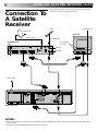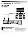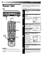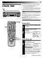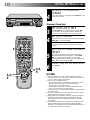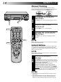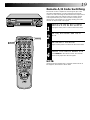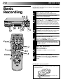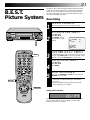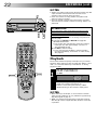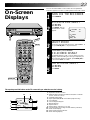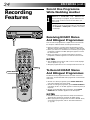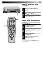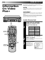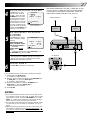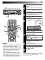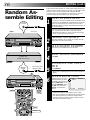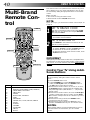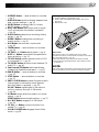
1
CONTENTS
VIDEO CASSETTE RECORDER
SAFETY FIRST
HR-J635EK
INSTALLING YOUR NEW RECORDER
2
Safety Precautions .................................... 2
Some Do’s And Dont’s ............................. 3
4
Basic Connections ................................... 4
Tune The TV To Your Video Recorder ...... 5
Connection To A Satellite Receiver .......... 6
Connection To A Stereo System ............... 7
INITIAL SETTINGS
8
Tuner Set .................................................. 8
Clock Set ................................................. 9
PLAYBACK
11
Basic Playback ....................................... 11
Playback Features .................................. 12
RECORDING
20
Basic Recording ..................................... 20
B.E.S.T. Picture System ........................... 21
On-Screen Displays ............................... 23
Recording Features ................................ 24
TIMER RECORDING
CH SET
A
B
OPERATE
STORE
CLOCK
C.MEMORY
DISPLAY
MODE
2
1
2
3
ADD TIME
4
5
6
DAILY
WEEKLY
7
8
C.RESET
AUX
CANCEL
0
START
STOP
9
TIMER
TV
PROG.
DATE
EXPRESS PROGRAMMING
AUDIO MONITOR
TV/VIDEO
(MONITOR)
TV
VCR
REW
SCE
N E FI N
DER
PROG C
HEC
K
TIMER
R . A . E D IT
1
G
PRO TV VOL.
3
IN /
ST A OUT
RT
OK
AUDIO
DUBBING
FF
6
OPERATE
EDITING
q
PUSH JOG
TV PROG /
JOG
VIDEO (MONO)L–AUDIO–R
ILLUMI GUIDE
26
Information On Video Plus+ .................. 26
Guide Channel Set .............................. 26
Video Plus+ Timer Recording ................. 28
Regular Timer Programming .................. 30
Check And Cancel Programmes .......... 32
Timer Warning .................................... 32
Auto SP/LP Timer ................................. 33
PDC Recording ................................... 33
SHUTTLE
34
Edit To Or From Another Video
Recorder ................................................ 34
Edit From A Camcorder ......................... 35
Random Assemble Editing ..................... 36
Audio Dubbing ...................................... 38
– TV PROG. +
SP/LP
AUTO SP / LP
TIMER
MULTI BRAND
REMOTE CONTROL UNIT
REMOTE CONTROL
TM
40
Multi-Brand Remote Control .................. 40
USING THE CONFIRMATION SCREEN
PAL
INSTRUCTIONS
41
Storing Channels Manually .................... 41
Delete A Channel .................................. 42
Change Station Preset Position ............... 42
Set Stations ............................................ 43
TV STATION AND ID LIST
45
TV STATION CHANNEL NUMBER GUIDE
46
TROUBLESHOOTING
47
QUESTIONS AND ANSWERS
49
INDEX
50
SPECIFICATIONS
55
PU30425-1790-2
2
SAFETY FIRST
Safety Precautions
The rating plate and the safety caution are on the rear of the unit.
WARNING: DANGEROUS VOLTAGE INSIDE
WARNING: TO PREVENT FIRE OR SHOCK HAZARD, DO NOT EXPOSE THIS UNIT TO RAIN OR
MOISTURE.
IMPORTANT
IMPORTANT
Connection to the mains supply in the United Kingdom.
DO NOT cut off the mains plug from this equipment. If
the plug fitted is not suitable for the power points in your
home or the cable is too short to reach a power point, then
obtain a proper safety approved extension lead/adapter or
consult your dealer.
BE SURE to replace the fuse only with an identical
approved type, as originally fitted, and to replace the fuse
cover.
If nonetheless the mains plug is cut off remove the fuse and
dispose of the plug immediately, to avoid a possible shock
hazard by inadvertent connection to the mains supply.
If this product is not supplied fitted with a mains plug then
follow the instructions given below:
DO NOT make any connection to the Larger Terminal
coded E or Green.
The wires in the mains lead are coloured in accordance
with the following code:
Blue to N (Neutral) or Black
Brown to L (Live) or Red
If these colours do not correspond with the terminal
identifications of your plug, connect as follows:
Blue wire to terminal coded N (Neutral) or coloured Black.
Brown wire to terminal coded L (Live) or coloured Red.
If in doubt — consult a competent electrician.
CAUTION
n When you are not using the recorder for a long period of
time, it is recommended that you disconnect the power
cord from the mains outlet.
n Dangerous voltage inside. Refer internal servicing to
qualified service personnel. To prevent electric shock or
fire hazard, remove the power cord from the mains
outlet prior to connecting or disconnecting any signal
lead or aerial.
n Please read the various precautions on p. 2 – 3 of this
instruction manual before installing or operating the
recorder.
n It should be noted that it may be unlawful to re-record
pre-recorded tapes, records, or discs without the consent
of the owner of copyright in the sound or video recording, broadcast or cable programme and in any literary,
dramatic, musical, or artistic work embodied therein.
The OPERATE button does not completely shut off mains
power from the unit, but switches operating current on and
off.
Video tapes recorded with this video recorder in the LP
(Long Play) mode cannot be played back on a single-speed
video recorder.
Failure to heed the following precautions may result in
damage to the recorder, remote control or video
cassette.
1. DO NOT place the recorder . . .
... in an environment prone to extreme temperatures or
humidity.
... in direct sunlight.
... in a dusty environment.
... in an environment where strong magnetic fields are
generated.
... on a surface that is unstable or subject to vibration.
2. DO NOT block the recorder’s ventilation openings.
3. DO NOT place heavy objects on the recorder or remote
control.
4. DO NOT place anything which might spill on top of the
recorder or remote control.
5. AVOID violent shocks to the recorder during transport.
MOISTURE CONDENSATION
TM
PAL
n Only cassettes marked "VHS" can be used with this
videorecorder.
n HQ VHS is compatible with existing VHS equipment.
n Video Plus+ and PlusCode are trademarks of Gemstar
Development Corporation. The Video Plus+ system is
manufactured under licence from Gemstar Development
Corporation.
Moisture in the air will condense on the recorder when you
move it from a cold place to a warm place, or under extremely
humid conditions—just as water droplets form in the surface of
a glass filled with cold liquid. Moisture condensation on the
head drum will cause damage to the tape. In conditions where
condensation may occur, keep the recorder turned on for a few
hours to let the moisture dry.
ABOUT HEAD CLEANING
Accumulation of dirt and other particles on the video heads
may cause the playback picture to become blurred or interrupted. Be sure to contact your nearest JVC dealer if such
troubles occur.
3
4-STEP QUICK SET UP
1
2
BASIC
CONNECTION
PAGE 4
3
TUNE THE
TV TO YOUR
VIDEO
RECORDER
PAGE 5
TUNER SET
PAGE 8
4
CLOCK SET
PAGE 9
Some Do's And Don'ts On The Safe
Use Of Equipment
This equipment has been designed and manufactured to meet international safety standards but, like any
electrical equipment, care must be taken if you are to obtain the best results and safety is to be assured.
DO read the operating instructions before you attempt to use the equipment.
DO ensure that all electrical connections (including the mains plug, extension leads and interconnections between pieces of equipment) are properly made and in accordance with the manufacturer's
instructions. Switch off and withdraw the mains plug when making or changing connections.
DO consult your dealer if you are ever in doubt about the installation, operation or safety of your equipment.
DO be careful with glass panels or doors on equipment.
DON'T continue to operate the equipment if you are in any doubt about it working normally, or if it is
damanged in any way — switch off, withdraw the mains plug and consult your dealer.
DON'T remove any fixed cover as this may expose dangerous voltages.
DON'T leave equipment switched on when it is unattended unless it is specifically stated that it is de-
DON'T
DON'T
DON'T
DON'T
DON'T
signed for unattended operation or has a standby mode. Switch off using the switch on the
equipment and make sure that your family knows how to do this. Special arrangements may need
to be made for infirm or handicapped people.
use equipment such as personal stereos or radios so that you are distracted from the requirements
of road safety. It is illegal to watch television whilst driving.
listen to headphones at high volume, as such use can permanently damage your hearing.
obstruct the ventilation of the equipment, for example with curtains or soft furnishings. Overheating will cause damage and shorten the life of the equipment.
use makeshift stands and NEVER fix legs with wood screws — to ensure complete safety always
fit the manufacturer's approved stand or legs with the fixings provided according to the instructions.
allow electrical equipment to be exposed to rain or moisture.
ABOVE ALL...
— NEVER let anyone especially children push anything into holes, slots or any other opening in the
case — this could result in a fatal electrical shock;
— NEVER guess or take chances with electrical equipment of any kind — it is better to be safe than
sorry!
4
INSTALLING YOUR NEW RECORDER
Basic Connections
Back of TV
RF Cable (provided)
21-pin SCART Cable
(provided)
Aerial terminal
21-pin SCART connector
Mains Power
Cord
It's essential that your video recorder be properly connected.
Follow these steps carefully. THESE STEPS MUST BE COMPLETED BEFORE ANY VIDEO OPERATION CAN BE PERFORMED.
1
2
3
CHECK CONTENTS
Make sure the package contains all of the accessories
listed in “Specifications” (Z pg. 55).
SITUATE RECORDER
Place the recorder on a stable, horizontal surface.
CONNECT RECORDER TO
TV
Mains outlet
The connection method you use depends on the type of
TV you have.
RF CONNECTION
● To Connect To A TV With NO AV Input Terminals . . .
a– Disconnect the TV aerial cable from the TV.
b– Connect the TV aerial cable to the ANT. IN jack
on the rear panel of the recorder.
c– Connect the provided RF cable between the RF
OUT jack on the rear panel of the recorder and the
TV’s aerial terminal.
Before operating the recorder, make sure the TV’s preset
is set to the VIDEO preset.
AV CONNECTION
● To Connect To A TV With AV Input Terminals . . .
a– Connect the aerial, recorder and TV as per “RF
CONNECTION”.
b– Connect the provided SCART cable between the
AV1 IN/OUT socket on the rear panel of the
recorder and the TV’s 21-pin SCART connector.
c– Set the RF OUT switch to OFF.
Before operating the recorder, make sure the TV is set to
the VIDEO (or AV) mode.
4
CONNECT RECORDER TO
MAINS
Plug the end of the mains power cord into a mains
outlet.
5
Tune The TV To Your Video
Recorder
TV Aerial Cable
R
L
RF output channel
adjustment screw
ANT. IN
AUDIO OUT
AV2 IN
32
40
RF OUT
ON–TEST–OFF
AV1 IN/OUT
PAUSE/
R.A.EDIT
RF OUT
RF OUT switch
The video recorder sends picture and sound signals via the RF
connecting cable to your TV on UHF channel 36.
* If you have connected the video recorder to your TV via both
the provided RF cable and 21-pin SCART cable, you can
ignore the rest of the following steps.
1
2
TURN ON THE RECORDER
Back of Recorder
3
Press OPERATE.
SELECT OUTPUT MODE
Set the RF OUT switch on the back of the recorder to
TEST.
4
SET TV PRESET
Set your TV to the video preset (UHF channel 36). Two
white bars appear on screen vertically.
● Tune the TV until the bars are as clear as they can be.
● Your TV should be set to the preset designated for use
with a video recorder, or to a spare preset if there is
not a specified video preset on your TV.
RESET OUTPUT MODE
Return the RF OUT switch to ON.
NOTE:
If some interference noise is continually seen on the screen,
consult your JVC dealer.
6
INSTALLING YOUR NEW RECORDER (cont'd)
Connection To
A Satellite
Receiver
The AV2 IN socket on the rear panel of your recorder allows
simple connection to a satellite receiver.
Aerial
Aerial terminal
Outdoor Unit
Back of TV
Satellite Cable
TV Aerial cable
21-pin SCART
connectors
Satellite Receiver
Unit
ANT. IN
DECODER
VCR
TV
RF OUT
EXT.2
EXT.1
Mains outlet
R
L
AUDIO OUT
ANT. IN
AV2 IN
32
40
RF OUT
ON–TEST–OFF
AV1 IN/OUT
PAUSE/
R.A.EDIT
RF OUT
Back of Recorder
NOTES:
● When connecting your recorder to a TV equipped with 21-pin SCART connectors, follow the illustration above using the cables
shown in gray.
● For details, check your satellite receiver’s instruction manual.
7
Connection To
A Stereo
System
These instructions enable you to connect your video recorder to
your Hi-Fi stereo system (if you have one) and listen to the
soundtrack through the stereo.
FM Tuner
CD Player
Stereo Amplifier
AUX IN or TAPE MONITOR
I
I I I I I I I I
I
I I
I
I
I I I I I I I I
I
I I
I
I I I I I I I I
I
I I
I
I
I
I
I
I
Audio Cable (not provided)
Mains outlet
Speaker
R
L
AUDIO OUT
Television
Speaker
ANT. IN
AV2 IN
32
40
RF OUT
ON–TEST–OFF
AV1 IN/OUT
PAUSE/
R.A.EDIT
RF OUT
AUDIO OUT
1
MAKE CONNECTIONS
Connect the AUDIO OUT L and R connectors on your
video recorder to the AUX IN or TAPE MONITOR
terminals on your stereo system's receiver or amplifier.
NOTES:
● When connecting your recorder's audio output connectors to
a stereo amplifier, make sure you connect L and R correctly.
● If NICAM TV broadcasts are receivable in your area, this
recorder can record them independently of the TV set and
play them back through the connected stereo system.
● When listening to sound through the connected stereo system,
turn the TV's volume down completely.
Back of Recorder
CAUTIONS:
● This recorder has a dynamic range of more than 80 dB with
regards to its Hi-Fi audio capability. It is recommended that
you check the maximum level if you are going to listen to the
Hi-Fi audio signals through a stereo amplifier. A sudden surge
in the input level to the speakers may damage them.
● Some speakers and televisions are specially shielded to
prevent television interference. If both are of the non-shielded
type, do not place the speakers adjacent to the TV set as this
can adversely affect the video playback picture.
8
INITIAL SETTINGS
1
The following procedure describes how to select automatic
channel setting.
OPERATE
Tuner Set
Your recorder needs to memorise all necessary stations in preset
positions in order to record TV programmes. ATS+ (Auto Tuning
System) automatically assigns all receivable stations in your
area to call them up with the TV PROG. buttons without going
through any vacant channels.
1
6
CH SET
TV PROG.
q
2
2,5
OPERATE
2
3
4
5
6
7
8
9
3
SH
PU
4
3
4
AUTO CH SET
MANUAL CH SET
GUIDE CH SET
SELECT MODE
“AUTO CH SET” is the
necessary mode for this
procedure, so simply press
OK to enter the selection.
AUTO CH SET
PLEASE WAIT
[CANCEL] : EXIT
VIEW CONFIRMATION
SCREEN
The stations your recorder
PR CH
ID
PR CH ID
01
40 BBC1 08
---located appear on a
02 46 BBC2 O9
---Confirmation screen —
03
43 ITV
10
---04
65
CH4
11
--preset positions (PR),
05
- - - - 12
---presets (CH) and station
06
- - - - 13
---07
- - - - 14
---names (ID – Z pg. 45). To
[ 5∞ ] : SELECT
view the next page of the
[CANCEL] : DELETE
: EDIT
listing, press PUSH
[CH SET ] : EXIT
JOG%fi . The blueback
screen and the program
currently being broadcast by the highlighted station
appear alternately for 5 seconds each.
5
∞
fi
fi
%
fi
G
JO
OK
Press and hold CH SET for
more than 2 seconds. The
Ch. Set Mode menu screen
to the right appears.
● The Auto Ch. Set screen
appears, and remains on
screen while the
recorder searches for
receivable stations.
TV PROG.
3
ACCESS CH SET MODE
MENU
1
0
1
Press OPERATE.
[5 ∞] : SELECT
: OK
[CANCEL] : EXIT
2
1
TURN ON THE RECORDER
%
%
NOTES:
● Fine tuning is performed automatically when you select
“AUTO CH SET”. If you want to perform it manually, refer to
page 44.
● To set the tuner manually, refer to “Storing Channels Manually”
(Z pg. 41).
5
RETURN TO NORMAL
SCREEN
Press CH SET.
● Using the Confirmation screen, you can skip or add
preset positions, enter station names and perform
other operations. Refer to page 41 for the procedures.
● Depending on reception conditions, the stations may
not be stored in order, and the station names may not
be stored correctly.
9
If you performed Auto Channel Set (Z pg. 8), the recorder’s
built-in clock is also set automatically. The Auto and Manual
clock setting procedures are necessary when . . .
– a power outage of more than 3 minutes occurs.
– the tuner has been set manually.
– the user desires to set the clock slightly ahead of the actual time.
– the clock was not set even after Auto Tuner Set was performed.
Whether you perform Auto or Manual clock setting, you can
use the convenient Just Clock function.
Just Clock
The Just Clock function provides accurate time keeping through
automatic adjustments at regular intervals, by reading data from
a PDC signal.
The Just Clock option appears in the Clock Set and Auto Clock
Set screens, and can be set “ON” or “OFF” (the default setting is
“ON”). Press OK until the Just Clock setting begins blinking,
then press PUSH JOG%fi to change the setting.
IMPORTANT: If you turn off Just Clock off, the accuracy of your
recorder’s built-in clock may be reduced, which could
adversely effect timer recording.
6
q
Both Auto and Manual clock setting procedures begin from step 3.
OPERATE
1
Preparation
2
2
3
4
5
6
7
8
9
2,4
O
CK
1
1
CL
1
OPERATE
Clock Set
0
2
TURN THE RECORDER ON
Press OPERATE.
ACCESS CLOCK SET
SCREEN
Press CLOCK on the
remote control. The Clock
Set screen appears.
CLOCK SET
TIME
DATE
0: 00
01 . 01
JUST CLOCK: ON
TV. PR
1
YEAR
00
5
[ ]: AUTO CLOCK SET
[5∞]:ADJUST =
:OK
[CLOCK] : EXIT
3
1
OK
PUSH JOG
3
Auto Clock Set
At the Clock Set screen,
press PUSH JOG . The
Auto Clock Set screen
appears and clock setting
begins.
%
3
SET CLOCK
AUTOMATICALLY
CLOCK SET
AUTO CLOCK SET
PLEASE
WAIT
JUST CLOCK: ON
TV. PR
1
● If "TV.PR" isn't set to the
preset position on which
Auto Clock Set data is
received, "ERROR"
appears, and then the screen from step 2 reappears.
To set "TV.PR", press OK to place the cursor next to it,
then cycle through the numbers by pressing PUSH
JOG%fi until the number representing the position in
which the station transmitting clock setting data
(BBC1, BBC2, etc.) is stored appears.
CONTINUED ON NEXT PAGE.
10
INITIAL SETTINGS (cont.)
4
6
RETURN TO NORMAL
SCREEN
Once clock setting is completed, press CLOCK to return
to the normal screen.
q
Manual Clock Set
3
4
4
5
6
7
8
9
O
3
CL
6
2
CK
2
1
0
5
3
1
3,4, PUSH JOG
5
OK
3,4,
5
6
SET DATE AND TIME
Press PUSH JOG%fi to set the hour, then press OK.
The “minutes” display begins blinking. Repeat the
procedure to set the minutes, day, month and year.
SET JUST CLOCK
The default setting is “ON”. Set as desired by pressing
PUSH JOG%fi, then press OK.
● If you set to “OFF”, you can disregard the next step as
you won’t be able to receive regular clock adjustments.
SET CLOCK DATA SOURCE
PRESET
The recorder is preset to receive clock setting and
adjustment data from preset position 1. Press PUSH
JOG%fi to set the preset position to the number
representing the station transmitting clock setting data
(BBC1, BBC2, etc.), then press OK.
START CLOCK OPERATION
Press CLOCK.
NOTES:
● Just Clock (when set to "ON") enables adjustment of the
recorder's built-in clock every hour on the hour, except for 11
o'clock in the evening and midnight.
● Just Clock is not effective when . . .
– the recorder’s power is on (unless the recorder is tuned to
the same preset selected in the Clock Set screen).
– the recorder is in the Timer mode.
– a difference of more than 3 minutes exists between the
built-in clock’s time and the actual time.
● The recorder’s clock is automatically adjusted at the start/end
of Summer Time.
● Auto clock setting and Just Clock may not function properly
depending on the reception condition.
● During Manual clock setting, if the day and month data are
invalid (such as 31st April), the month digits are cleared
automatically and the day digits begin blinking. Input the
correct data.
● If, in step 3 of the Manual clock setting procedure, the year
digits are automatically cleared and the day digits begin
blinking, it is possible that you have input 29th February for a
non-leap year. Input the correct data.
11
PLAYBACK
The easiest, most basic operation possible with your video
recorder is tape playback. Already-recorded signals on a video
tape are read by your video recorder and displayed on your TV
just like a TV programme.
SHUTTLE
Basic
Playback
2
1
6
PLAY
STOP/EJECT
q
4
2
3
4
5
6
7
8
9
4
0
FF
START PLAYBACK
Press PLAY. “BEST” appears blinking in the recorder's
display panel for 5 seconds (Z pg. 22).
● Playback picture quality of LP recordings will not be
as high as SP recordings.
STOP PLAYBACK
Press STOP on the remote or STOP/EJECT on the
recorder’s front panel. Then press STOP/EJECT to
remove the cassette.
2
Usable cassettes
3
ST
O
P
REW
4
If the tape is advanced past the start point, press REW
or turn the SHUTTLE ring to the left and release it.
To go forward, press FF or turn the SHUTTLE ring to the
right and release it.
AY
2
FIND PROGRAMME START
POINT
PL
3
2
3
2
1
Make sure the window side is up, the rear label side is
facing you and the arrow on the front of the cassette is
point toward the recorder. Don’t apply too much
pressure when inserting.
● The recorder power comes on automatically and the
counter is reset to 0:00:00.
● If the record safety tab has been removed, playback
begins automatically.
1
3
LOAD A CASSETTE
1
● Compact VHS camcorder recordings can be played on
this video recorder. Simply place the recorded cassette
into a VHS Cassette Adapter and it can be used just like
any full-sized VHS cassette.
● This video recorder can record on regular VHS and
Super VHS cassettes. However, it will record and play
back regular VHS signals only. It is not possible to play
back a recorded Super VHS tape.
12
PLAYBACK (cont.)
Take advantage of special functions possible with the recorder’s
controls or the remote control.
Playback
Features
NOTE:
Refer to the SHUTTLE ring illustration below as you read the
following procedures.
s
y
sea
search
6
Pl
a
ard
Forw rch
Reverse
la
Re
p ve
SHUTTLE
Slow
motio
n
v e rs e
Re low
e
rs
y
PAUSE
Still
PLAY
TV PROG.
JO
G
q
Still Picture/Frame-ByFrame Playback
1
2
1
2
3
4
5
6
7
8
9
2
0
PAUSE DURING PLAYBACK
Press PAUSE. If there is vertical jitter, use the TV PROG.
buttons to correct the picture.
ACTIVATE FRAME-BYFRAME PLAYBACK
Turn the JOG dial to the right for forward frame-byframe playback, or to the left for reverse frame-by-frame
playback.
OR
Press PAUSE.
TV PROG.
OR
.
%
or
fi
Press PUSH JOG
PLAY
To resume normal playback, press PLAY.
PAUSE
3
Slow Motion
1
PUSH JOG
1
ACTIVATE SLOW-MOTION
PLAYBACK
During playback or still, turn the SHUTTLE ring to the
right for forward slow motion, or to the left for reverse
slow motion (refer to the illustration above).
OR
During still picture, press PAUSE and hold for 2
seconds, then release. Press and release again to return
to still picture.
OR
To resume normal playback, press PLAY.
or
.
%
fi
During still picture, press and hold PUSH JOG
Release to return to still picture.
13
SHUTTLE
Variable-Speed Search
6
1
ACTIVATE VARIABLE-SPEED
SEARCH
During playback or still, turn the SHUTTLE ring to the
right for forward variable-speed search, or to the left for
reverse variable-speed search (refer to the illustration on
page 12).
q
OR
.
%
or
fi
During playback, press PUSH JOG
PLAY
● The more times you press, the faster the playback
picture moves.
● To decrease speed, press the button for the opposite
direction.
To resume normal playback, press PLAY.
High-Speed (Turbo) Search
2
1
2
3
4
5
6
7
8
9
1
PL
AY
0
FF
REW
ACTIVATE HIGH-SPEED
SEARCH
During playback or still, turn the SHUTTLE ring all the
way to the right for forward high-speed search, or to the
left for reverse high-speed search.
● For forward search with a visible picture, turn the
SHUTTLE ring all the way to the right and release it
within 1 second.
● For reverse search with a visible picture, turn the
SHUTTLE ring all the way to the left and release it
within 1 second.
OR
Press FF for forward high-speed search, or REW for
reverse high-speed search.
3
1
PUSH JOG
● For short searches, press and hold FF or REW for over
2 seconds. When released, normal playback resumes.
To resume normal playback, press PLAY.
14
PLAYBACK (cont.)
Manual Tracking
Your video recorder is equipped with automatic tracking
control. During playback, you can override this and adjust the
tracking manually by pressing the TV PROG. buttons.
6
q
RE
VI
TV PROG.
EW
1
2
REVIEW
2
1
2
3
4
5
6
7
8
9
0
TV PROG.
3
OVERRIDE AUTOMATIC
TRACKING
Press SP/LP on the remote to engage manual tracking.
ADJUST TRACKING
MANUALLY
Press TV PROG. + or – to adjust tracking.
RETURN TO AUTOMATIC
TRACKING
Press SP/LP on the remote to re-engage automatic
tracking.
NOTE:
When a new tape is inserted, the recorder enters the automatic
tracking mode automatically.
SP/LP
Instant ReView
3
1
Simply by pressing a single button, the recorder power comes
on, rewinds, and begins playback of the last timer-recorded
programme. If you have several programmes recorded, you can
easily access any of them.
NOTE:
Before starting, make sure that the recorder is off and that the
Timer mode is disengaged.
1
ACTIVATE INSTANT
REVIEW
Press REVIEW. The recorder power comes on and the
recorder searches for the index code indicating the start
of the last timer-recorded programme. Once it’s found,
playback begins automatically.
The front display panel tells you how many
programmes have been recorded. If you have, for
example, 3 programmes, “REV 3” appears and blinks.
To watch the first of the 3 programmes, press REVIEW
three times. The recorder searches and begins playback
automatically. You can access a programme as far as 9
index codes away from the current tape position.
NOTES:
● Instant ReView is not possible while the recorder is in the
Timer mode.
● The number displayed on the front display panel may not
match the actual number of timer-recorded programmes
when one or more of them is a PDC recording (Z pg. 33).
15
Repeat Playback
OPERATE
Your video recorder can automatically play back the whole tape
20 times repeatedly.
6
ST
O
PLAY
P
q
Y
OR
C.
M
ME
OPERATE
1
2
2
1
2
3
4
5
6
7
8
9
3
0
START PLAYBACK
Press PLAY.
ACTIVATE REPEAT
PLAYBACK
Press PLAY and hold for over 5 seconds, then release.
● The Play indicator (
) on the display panel blinks
slowly.
● The tape plays 20 times automatically, and then
stops.
STOP PLAYBACK
Press STOP at any time to stop playback.
PLAY
NOTE:
FF
Pressing PLAY, REW , FF or PAUSE also stops Repeat Playback.
Next Function Memory
REW
PAUSE
P
O
ST
3
1
You can set your recorder's power to go off automatically after
the tape is fully rewound. Before starting, make sure the
recorder is in the Stop mode.
For Automatic Power Off After Tape Rewind . . .
. . . press REW, then press OPERATE within 2 seconds.
NOTE:
If you want the power to be turned off automatically when the
counter reads “0:00:00” (instead of at the beginning of the
tape), press C.MEMORY so that the “M” mark appears before
pressing REW.
Tape Position Indicator
The tape position indicator appears
on screen when, from the Stop
mode, you press FF, REW or
perform an Index Search. The
position of “5” in relation to “0”
(beginning) or “+” (end) shows you
where you are on the tape.
”On-Screen” (Z pg. 23) must be
set to “ON”, or the indicator will
not appear.
3
0
+
+
+
1:23:45
REMAIN 2:35
NOTE:
Depending on the type of tape used, there may be times when
the indication is not correct.
16
PLAYBACK (cont.)
Index Search
Your recorder automatically marks
index codes at the beginning of
each recording. This function gives
you quick access to any one of 9
index codes in either direction.
£ 2
NOTE:
6
q
Before starting, make sure the
recorder is in the Stop mode.
fi
Press PUSH JOG or (™ or £). “™ 1” or
“£ 1” is displayed on screen and search begins in
the corresponding direction.
fi
2
1
%
● To access index codes 2 through 9, press PUSH JOG
or repeatedly until the correct index number is
displayed.
Ex.: To locate the beginning of B from the current
position, press PUSH JOG twice.
To locate the beginning of D from the current
position, press PUSH JOG once.
Current position
fi
DISPLAY
%
1
ACTIVATE INDEX SEARCH
3
4
5
6
7
8
9
%
2
0
A
–2
B
C
–1
D
1
E
2
F
3
Index number
● When the specified index code is located, playback
begins automatically.
Tape Remaining Time
3
1
PUSH JOG
1
DISPLAY REMAINING TIME
Press DISPLAY until the time remaining on the tape
appears.
● By pressing the DISPLAY button, you can change the
display to show the counter reading, tape remaining
time, or clock time.
NOTE:
● Depending on the type of tape used, there may be times
when the tape remaining time reading may not appear right
away, or is not correct. "- - : - -" may sometimes appear, or the
display may blink on occasion.
17
SHUTTLE
Scene Finder
This function helps you check contents of unlabeled recorded
tapes at the touch of a single button.
Search
Search
FF
REW FF
5 seconds
6
10 minutes
on counter
Search
REW FF
5 seconds
10 minutes
on counter
REW
5 seconds
NOTE:
q
STOP
C. MEMORY
Scene Finder cannot be used when the recorder is in the Record
mode.
1
2
3
4
5
6
7
8
9
Press SCENE FINDER. The recorder starts forward highspeed search for 5 seconds and then fast-forwards 10
minutes on the counter. This cycle is repeated until the
end of the tape is reached.
● To start Scene Finder in the reverse direction, press
SCENE FINDER and then turn the SHUTTLE ring to
the left (or press the remote’s REW button) within 2
seconds. This cycle is repeated until the beginning of
the tape.
● During Scene Finder, the following indications appear
on the display panel:
2
1
ACTIVATE SCENE FINDER
0
C.RESET
FF
REW
2
STOP SCENE FINDER
Press STOP.
NOTES:
P
1
O
3
ST
SCENE FINDER
● During Scene Finder high-speed search, you can also hear the
tape sound. During fast forward or rewind, you hear the
current TV sound instead.
● Scene Finder does not function during Index Search.
Counter Memory
Returns to the counter reading of “0:00:00” to conveniently find
a specific place on the tape automatically.
1
2
SET COUNTER MEMORY
Press C. RESET during playback at a point you wish to
locate later. The counter reads “0:00:00”. Then press
C.MEMORY, and “M” appears in front of the counter
digits.
ACTIVATE COUNTER
MEMORY
When you wish to return to the designated point, press
STOP and then REW or FF.
● The tape rewinds or fast-forwards and stops at about
0:00:00 automatically.
● To cancel Counter Memory, press C.MEMORY again.
18
PLAYBACK (cont.)
NTSC Playback
Your video recorder is equipped with NTSC circuitry that can
play back NTSC tapes.
6
q
PLAY
1
2
2
1
2
3
4
5
6
7
8
9
0
LOAD A CASSETTE
Insert a cassette recorded in NTSC.
START PLAYBACK
Press PLAY. “NT” appears on the display panel.
● Some TVs shrink the picture vertically and place
black bars at the top and bottom of the screen. This is
not a malfunction on the part of either the video
recorder or the TV.
● The picture may roll up and down. This can be
corrected using the V-HOLD control found on some
TVs. (This cannot be corrected if the TV does not
have a V-HOLD control.)
● The counter and tape remaining time readings will be
incorrect.
● During search, still, or frame-by-frame playback, the
picture will be distorted, and there may be a loss of
colour.
● Depending on the type of TV, the top and bottom
portions of superimposed displays may be cut off
during NTSC playback.
PL
AY
AUDIO MONITOR
Soundtrack Selection
Your video recorder is capable of recording three soundtracks (HI-FI L, HI-FI R and NORM) and will play back the one you select.
During Playback
Pressing AUDIO MONITOR on the remote control changes the soundtrack being played back as follows:
TRACK
Recorder's Front Panel
On-Screen Display
USE
L+R
HI FI
For Hi-Fi stereo tapes
L
HI FI
For main audio of Bilingual tapes
R
HI FI
For sub audio of Bilingual tapes
NORM
NORM
For audio-dubbed tapes
L + R + NORM
HI FI
NORM
For audio-dubbed tapes
NOTES:
● "L + R" should normally be selected. In this mode, Hi-Fi stereo tapes are played back in stereo, and the NORM track is played back
automatically for tapes with only normal audio.
● For instructions on recording NICAM stereo and bilingual programmes, refer to page 24.
● Bilingual programmes are not currently broadcast in the U.K.
● "ON SCREEN" must be set to "ON" or the on-screen displays will not appear (Z pg. 23).
19
Remote A/B Code Switching
6
q
OPERATE
A/B CODE
2
1
2
3
4
5
6
7
8
9
0
The remote control is capable of controlling two JVC video
recorders independently; one set to respond to the remote
control’s A code control signals and another set to respond to B
code control signals. The remote control is preset to send A
code signals because your video recorder is initially set to
respond to A code signals. You can easily modify your video
recorder to respond to B code signals.
1
2
3
4
REMOVE POWER SUPPLY
Unplug the mains power cord from the mains outlet.
SET A/B CODE SWITCH
Set to B.
RE-SUPPLY POWER
Plug the mains power cord back into the mains outlet.
TURN THE RECORDER ON
Press OPERATE on the remote control. The recorder
will now only respond to B code signals.
NOTE:
Some TV sets may malfunction in response to the B mode. If
this happens, switch back to the A mode.
3
1
20
RECORDING
TV signals being received by the recorder’s built-in tuner can be
recorded onto a video tape. You can “capture” a TV programme
using your video recorder.
Basic
Recording
1
TV PROG.
PAUSE
5
2
6
EC
PLAY
6
2
NUMBER
2
3
4
5
6
7
8
9
5
3
4
2
1
● The counter is reset to 0:00:00 and the recorder
power comes on automatically.
CHOOSE A PROGRAMME
Press TV PROG. +/– or the NUMBER keys to select the
preset you wish to record. The name of the station
appears in the recorder’s display panel for 5 seconds,
followed by the preset position number. (Only stations
that appear in the Confirmation screen will be displayed.)
T
CO
O
ST
2
Insert a cassette with the record safety tab intact.
● The TV PROG. dial can also be used to select a preset.
P/
EJ
P
/L
4
3
RE
SP
TV PROG.
RD
q
LOAD A CASSETTE
SET TAPE SPEED
Press SP/LP. Check the SP/LP indicator on the recorder
display panel to confirm the selected tape speed.
● Picture quality of LP recordings will not be as high as
SP recordings.
START RECORDING
Press and hold RECORD and PLAY on the remote
control, or press RECORD on the recorder.
B.E.S.T. takes place at the beginning of both the
first SP and the first LP recording after inserting the
cassette (Z pg. 21).
0
TV PROG.
3
PLAY
4,5
PAUSE
RECORD
ST
O
P
4
SP/LP
1
6
3
2
5
5
6
PAUSE/RESUME
RECORDING
Press PAUSE. Press PLAY to resume recording.
STOP RECORDING
Press STOP on the remote control or STOP/EJECT on
the recorder. Then press STOP/EJECT to remove the
cassette.
Accidental erasure prevention
● To prevent accidental recording on a recorded cassette,
remove its safety tab. To record on it later, cover the hole
with adhesive tape.
Record safety tab
21
B.E.S.T.
Picture System
The B.E.S.T. (Biconditional Equalised Signal Tracking) system
checks the condition of the tape in use during recording and
playback, and compensates to provide the highest-possible
recording and playback pictures. The default setting for both
recording and playback is “ON”.
Recording
1
6
RECORD
q
2
LOAD A CASSETTE
Insert a cassette with the record safety tab intact.
● The recorder power comes on automatically.
ACCESS MODE SELECT
SCREEN
Press MODE. The OnScreen/B.E.S.T. screen
appears.
ON SCREEN
: ON
B.E.S.T.
: ON
5
[5∞]: SELECT
[ ]: ON/OFF
[MODE] : EXIT
MODE
2
3
4
5
6
7
8
9
PLAY
0
RECORD
3
1
3
The default setting is “ON”. If this is the case, go to step
4. If not, press PUSH JOGfi to place the pointer next to
“B.E.S.T.”, then press PUSH JOG to set to “ON”.
4
5
Press MODE.
%
2
1
CONFIRM B.E.S.T. STATUS
CLOSE MODE SELECT
SCREEN
START RECORDING
Press and hold RECORD and PLAY on the remote, or
RECORD on the recorder.
● The recorder spends approximately 7 seconds
assessing the condition of the tape, then begins
recording.
● When the "BEST" indicator begins blinking, that
means adjustment is complete.
PUSH JOG
Display Panel Indication
As the tape check progresses, the “– –” marks on the display
panel increase upward. Once the "BEST" indicator starts
blinking, the check is complete.
22
RECORDING (cont.)
NOTES:
PAUSE
● The B.E.S.T. system works for both SP and LP modes only after
a tape has been inserted and the Record mode is first
initiated. It does not work during recording.
● In the case of timer recording, the B.E.S.T. system works
before recording is initiated.
● Once the cassette is ejected, the B.E.S.T. data is cancelled.
The next time the cassette is used for recording, B.E.S.T. is reperformed.
6
q
2
1
2
3
4
5
6
7
8
9
PLAY
RECORD
ATTENTION:
Since the B.E.S.T. system works before recording actually
starts, there is a delay of approximately 7 seconds after
RECORD and PLAY on the remote are pressed, or RECORD
on the recorder is pressed. To make sure you record the
desired scene or programme in its entirety, first perform the
following steps:
1) Press and hold PAUSE and RECORD to engage the
RECORD PAUSE mode.
● The recorder then automatically checks the condition
of the tape and, after approximately 7 seconds, reenters RECORD PAUSE.
2) Press PLAY to start recording.
● If you want to bypass the B.E.S.T. system and begin
recording immediately, set “B.E.S.T.” to “OFF” in step
3 on page 21.
Playback
0
PLAY
The recorder assesses the quality of the tape once you initiate
playback. When watching a tape recorded with “B.E.S.T.” set to
“ON”, it is recommended that you leave B.E.S.T. on during
playback as well.
PAUSE
RECORD
3
1
START PLAYBACK
Press PLAY.
1
● The recorder adjusts the playback picture quality
based on the quality of the tape in use.
● B.E.S.T. is active during Auto Tracking. “BEST”
appears blinking on the recorder’s display panel.
NOTES:
● When watching a rental tape, or one recorded on another
video recorder, set B.E.S.T. to your preference by performing
steps 2 through 4 on page 21.
● "BEST" only appears at the beginning of automatic tracking.
Even though it doesn't appear after that, the B.E.S.T. function
is operative.
23
You can choose whether or not to have various operational
indicators appear on screen, by setting this function ON or OFF.
On-Screen
Displays
1
2
6
OPERATE
q
TURN ON THE RECORDER
Press OPERATE.
ACCESS MODE SELECT
SCREEN
Press MODE. The OnScreen/B.E.S.T. screen
appears.
ON SCREEN
: ON
B.E.S.T.
: ON
5
[5∞]: SELECT
[ ]: ON/OFF
[MODE] : EXIT
E
RAT
OPE
MODE
2
1
2
3
4
5
6
7
8
9
3
5
3
1
The pointer should already be next to “ON SCREEN”. If
not, press PUSH JOG%fi to place it there.
ENABLE/DISABLE
ON-SCREEN DISPLAY
The default setting is “ON”, so if you want on-screen
displays, leave the setting as is and go to step 5. If you
don’t want the displays to appear, press PUSH JOG
to set “ON SCREEN” to “OFF”.
%
4
0
SELECT MODE
CLOSE MODE SELECT
SCREEN
Press MODE.
PUSH JOG
The superimposed indication on the TV screen tells you what the recorder is doing.
13
1
q6
2
5
6
7
9
11
PR. 12 ABCD
] SP
23 : 59
31. 12. 96 – WARNING–
TIMER RECORDING
TO START SOON
[CANCEL]
ST NICAM
+
+
+
+
0
HI FI
M –9 : 59 : 59
NORM
REMAIN 9 : 59
4
3
8
10
12
1– Operation mode indicators
2– Preset position number and station name/Aux. indicator
(AUX1, AUX2 or F-AUX)
3– Cassette loaded mark
4– Tape speed SP/LP/EP (EP is for NTSC playback only)
5– Clock display
6– Current day/month/year
7– NICAM display
8– Tape direction
9– Tape position indicator (Z pg. 15)
10– Counter display (including Counter Memory indicator)
11– Audio mode display
12– Tape remaining time indicator
13– Timer warning display
24
RECORDING (cont.)
Record One Programme
While Watching Another
Recording
Features
1
SELECT PRESET TO WATCH
Once recording is in progress, all you need to do is to
set the preset controls on the TV for the station you
wish to view.
● The programme selected with the TV’s preset controls
appears on the TV screen while the one selected with
the TV PROG. or PUSH JOG%fi buttons is recorded
on the tape.
6
q
TV PROG.
Receiving NICAM Stereo
And Bilingual Programmes
Your recorder is equipped with a digital stereo sound decoder
for reception of NICAM stereo and bilingual broadcasts.
● When you switch to a channel that is broadcasting in stereo,
"NICAM" and "ST" (stereo) appear on screen for a few seconds.
● When you switch to a channel that is broadcasting a bilingual
programme, "NICAM" and "BIL" (Bilingual) appear on screen
for a few seconds.
● When you switch to a channel broadcasting a monaural
programme, "NICAM" appears on screen for a few seconds.
2
1
2
3
4
5
6
7
8
9
NOTES:
● "ON SCREEN" must be set to "ON" or the on-screen displays
will not appear (Z pg. 23).
● Bilingual programmes are not currently broadcast in the U.K.
0
TV PROG.
To Record NICAM Stereo
And Bilingual Programmes
AUDIO MONITOR
The NICAM audio programme will be recorded on the Hi-Fi
audio track, and the Standard audio programme on the Normal
audio track.
3
1
PUSH JOG
● To listen to a stereo programme, press AUDIO MONITOR
until "L+R" appears on the front panel.
● To listen to a bilingual programme, press AUDIO MONITOR
until either "HI FI L" or "HI FI R" appears on the front panel (as
required).
● To listen to the Standard audio programme, press AUDIO
MONITOR until "NORM" appears on the front panel.
NOTES:
● If the NICAM stereo signal becomes weak, the broadcast is
automatically recorded in monaural for better quality.
● Before playing back a programme recorded in NICAM stereo,
or a bilingual programme, refer to "Soundtrack Selection"
( Z pg. 18).
25
Elapsed Recording Time
Indication
You can check the exact time of a recording.
1
6
RECORD
q
2
SET COUNTER DISPLAY
Press DISPLAY until a counter reading appears on the
dispay panel.
RESET COUNTER
Press C. RESET before starting recording or playback.
● The counter is reset to “0:00:00” and shows the exact
elapsed time as the tape runs.
DISPLAY
2
1
2
3
4
5
6
7
8
9
Instant Timer Recording (ITR)
This easy method lets you record for from 30 minutes to 6 hours
(selectable in 30-min. increments), and shuts the recorder off
after recording is finished.
0
C.RESET
1
2
3
1
3
START RECORDING
Press RECORD on the recorder.
ENGAGE ITR MODE
Press RECORD again. ITR blinks and 0:30 appears on
the front display panel.
SET RECORDING
DURATION
If you want to record for more than 30 minutes, press
RECORD to extend the time. Each press extends
recording time by 30 minutes.
NOTE:
You can only perform ITR using the RECORD button on the
recorder's front panel.
26
TIMER RECORDING
Information
On Video
Plus+
With Video Plus+, timer programming is greatly simplified
because each TV programme has a corresponding code number
which your recorder is able to recognise.
NOTE:
“Guide Channel” (GUIDE CH) refers to the assigned TV station
numbers, according to broadcast area, for Video Plus+ timer
recording.
IMPORTANT
Perform the following procedure after the channel setting steps
on pages 8 and 41 – 43, and after the Clock Set procedure on
page 9.
After setting the Guide Channel, the station names and preset
positions may be incorrect if you stored or skipped channels. In
this case, re-perform Guide Channel setting.
6
q
CH SET
Guide Channel Set
1
Preset position
Station name
1
BBC 1
2
BBC 2
2
3
3
ITV
4
5
6
4
CH 4
7
8
9
0
CANCEL
3
1
PUSH JOG
(Ex.)
1
2
NUMBER
MAKE LIST OF STORED
STATION NAMES AND
PRESET POSITIONS
OK
2
3
ACCESS CH. SET MODE
MENU SCREEN
Press and hold CH SET for over 2 seconds. The Ch. Set
Mode Menu screen appears.
SELECT MODE
Press PUSH JOG%fi to
place the cursor next to
“GUIDE CH SET”, then
press OK. The Guide Ch.
Set screen appears.
AUTO CH SET
MANUAL CH SET
GUIDE CH SET
[5∞] : SELECT
: OK
[CANCEL] : EXIT
27
4
5
4
ENTER PLUSCODE NUMBER
Press OK, and a cursor
appears under “GUIDE
CH SET”. Then, using the
NUMBER keys, input the
PlusCode (found in most
TV listings) of a program
scheduled to be broadcast
on each station on the list
from step 1, starting at the
top. If you enter the wrong
number, press CANCEL and
input the correct number.
GUIDE CH SET
12345 5
GUIDE CH
TV PROG
1
1
Satellite Antenna
Cable
Satellite
Receiver
Cable
system
[0 – 9] : VIDEO PLUS +
: OK
When entering a
PlusCode for BBC 1
ENTER PRESET POSITION
NUMBER
Press OK and the display
GUIDE CH SET
under “TV PROG” begins
blinking.
GUIDE CH
TV PROG
If the blinking number
250
39
under “TV PROG” agrees
with the preset position . . .
[5∞] : SELECT
. . . press OK.
: OK
If the numbers do not
agree . . .
. . . input the preset position using PUSH JOG%fi or
the NUMBER keys, then press OK.
● If you input the PlusCode number of a program that
has already aired, “ERROR” appears on screen for a
few seconds. Input the correct PlusCode number.
● Repeat steps 4 and 5 as necessary.
6
THE SATELLITE RECEIVER IS SHOWN CONNECTED TO THE
“AV2 IN” (SCART) CONNECTOR AND THE CABLE SYSTEM
CONNECTED VIA THE AERIAL SOCKET AND TUNED TO,
FOR EXAMPLE, PRESET POSITION 5 ON YOUR TV.
CLOSE MENU
Press CH SET and selection is complete.
%
If you already know the Guide Channel number for a station . . .
1– After step 3, press PUSH JOG .
● ”GUIDE CH” begins blinking.
2– Enter the Guide Channel number using the NUMBER keys
or PUSH JOG%fi, then press PUSH JOG .
● “TV PROG” begins blinking.
3– Enter the preset position using the NUMBER keys or
PUSH JOG%fi, then press PUSH JOG .
● Repeat 2 and 3 as necessary.
4– Press CH SET.
%
%
NOTES:
● If you own a satellite receiver, connect it to the AV2 connector on the back of the recorder. Then, in step 5 above, set the
input mode to "AUX2" by pressing NUMBER key "0" or TV
PROG. +/–. Make sure no cables are connected to the front
panel connectors when performing this procedure.
● If you’re receiving broadcasts via a cable box through preset
“5” (example) on your recorder, set “TV PROG” for “5” in
step 5.
● After selecting the programme you wish to record from your
cable system or satellite receiver, set the system’s timer — if
your cable or satellite receiver does not have a timer, leave it
switched on.
TV Receiver
28
TIMER RECORDING(cont.)
Video Plus+
Timer
Recording
Before performing Video Plus+ Timer Recording, be sure to
read "Information on Video Plus+" on page 26.
During Video Plus+ and regular timer programming, the IllumiGuide feature tells you which button on the remote control
must be pressed next by lighting it up. To use this feature, press
ILLUMI GUIDE before performing step 1. (PROG, REW, PLAY,
FF light up at this time.)
If you aren't going to use the Illumi-Guide feature, go directly to
step 1.
1
ACCESS TIMER PROGRAMMING SCREEN
Press PROG.
TIMER PROGRAMMING
[0 – 9] : VIDEO PLUS+
[+/-] : EXPRESS PROGRAMING
[CANCEL] : EXIT
The front display panel looks like this:
6
q
● If you are using the Illumi-Guide feature, the
following buttons will light up: NUMBER keys (0–9),
START +/–, STOP +/–, DATE +/–, TV PROG +/–, and
CANCEL.
2
2NUMBER
1
2
3
4
5
6
7
8
9
2
0
CANCEL
ENTER PLUSCODE NUMBER
Press the NUMBER keys to
enter the PlusCode
number of a programme
you wish to record.
V I D E O
P L U S +
1 2 3 4 5 6 7 8 5
● If you make a mistake,
[0 – 9] : INPUT
press CANCEL and then
: OK
input the correct
number.
The PlusCode number you enter appears on the front
display panel:
1
OK
3
PROG.
1
3
ILLUMI GUIDE
When Using The Illumi-Guide Feature
● Buttons light or blink on the remote control for
approximately 10 seconds. If the button or buttons extinguish
during timer programming, press ILLUMI GUIDE and the
button or buttons previously lit or blinking come back on. If
the button or buttons do not re-light or start blinking again,
press CANCEL and re-perform the timer programming
procedure from the beginning.
● If for some reason the remote control's signal is not received
by the video recorder, press CANCEL and re-perform the
timer programming procedure from the beginning.
● If you are using the Illumi-Guide feature, OK blinks
when the following buttons are lit: NUMBER keys (0–
9) and CANCEL.
29
TIMER
6
3
6
4
SP/LP
START
21 : 00
SP
DATE
25. 12
=
STOP
22 : 00
ON
TV PROG
1
BBC1
SP/LP
● If you are using the Illumi-Guide feature, OK blinks.
ADD TIME
C
D
:P
CANCEL
PROGRAM 1
VIDEO PLUS+ 12345678
SP
4
2
3
Press OK, and the Video
Plus+ Program screen
appears (if you’re just
starting out, “Program 1”
appears).
● If the number you
entered is invalid,
:OK
“ERROR” appears. Press
CANCEL and input a valid PlusCode number.
The front display panel looks like this:
q
4
ACCESS VIDEO PLUS+
PROGRAM SCREEN
1
2
4
5
3
ILY
DA
6
7
8
9
WEEKLY
TIMER
0
6
5
3
1
OK
3
6
SET TAPE SPEED
Press SP/LP to set the tape speed.
IMPORTANT
If you’re not receiving PDC (Programme
Delivery Control), press
: PDC (NUMBER key
“7”) to set to "OFF" (Z pg. 33).
RETURN TO NORMAL
SCREEN
Press OK.
● Repeat steps 1 – 5 for each additional programme.
ENGAGE RECORDER’S
TIMER MODE
Press TIMER.
NOTE:
For safety, your recorder disables all other functions while in the
Timer mode. If you want to use the recorder but its Timer mode
is engaged, press TIMER and all other functions are operable.
To re-engage the timer, press TIMER.
Satellite Receiver Users
To timer-record a satellite broadcast using Video Plus+,
perform steps 1 – 6 and, before the selected programme
begins, select the appropriate channel on the satellite
receiver. Then set the receiver's timer. If your satellite
receiver doesn't have a timer, leave the unit's power
switched on.
To Delay The Stop Time . . .
. . . press ADD TIME after pressing OK in step 3. Each time you
press, the Stop time is delayed by 5 minutes (meaning that 5
minutes of recording time is added). You can easily compensate
for anticipated programme schedule delays this way.
To Timer-Record Weekly Or Daily Serials . . .
. . . after pressing OK in step 3, press WEEKLY (NUMBER key
“9”) for weekly serials or DAILY (NUMBER key “8”) for daily
serials (Monday – Friday).
You can programme this recorder to timer-record as many as 8
programmes. If you try to programme the recorder to record a
ninth, "PROGRAM FULL" appears on screen and "FULL"
appears on the front display panel. To record the extra
programme, you must first cancel any unnecessary programmes
(Z pg. 32).
30
TIMER RECORDING(cont.)
Regular Timer
Programming
If you don’t know the PlusCode number for the programme you
wish to record, use the following procedure to set your recorder
to timer-record the programme.
Or you can use the Illumi-Guide feature, where the remote
control tells you which button to press next by lighting it up. To
use the Illumi-Guide feature, press ILLUMI GUIDE before
performing step 1. (PROG, REW, PLAY, FF light up at this time.)
If you aren't going to use the Illumi-Guide feature, go directly to
step 1.
Remember, the clock must be set before you can progamme
the timer (Z pg. 9).
6
q
1
2
ACCESS TIMER PROGRAMMING SCREEN
Press PROG.
● If you are using the Illumi-Guide feature, the following
buttons will light up: NUMBER keys (0–9), START +/–,
STOP +/–, DATE +/–, TV PROG +/–, and CANCEL.
ACCESS PROGRAMME
SCREEN
Press START +/–. (If you’re
just starting out, “Program
1” appears.)
2
1
2
3
4
5
6
7
8
9
PROGRAM 1
START
–:––
SP
STOP
–:––
ON
DATE
25. 12
TV PROG
––
[+ –] : SET =
: OK
The front display panel looks like this:
0
CANCEL
SP
START+/–
2,3
1
● If you are using the Illumi-Guide feature, the following
buttons will light up: START +/–, STOP +/–, DATE +/–,
and TV PROG +/–.
3
PROG.
3
1
ILLUMI GUIDE
ENTER PROGRAMME
START TIME
Press START +/– to enter
the time you want
recording to start.
PROGRAM 1
START
21 : 00
SP
● Press and hold START
DATE
+/– to move in 3025. 12
minute increments, or
[+ –] : SET =
press and release
repeatedly to move 1
minute at a time.
The front display panel looks like this:
STOP
–:––
ON
TV PROG
––
: OK
When Using The Illumi-Guide Feature
● Buttons light or blink on the remote control for
approximately 10 seconds. If the button or buttons extinguish
during timer programming, press ILLUMI GUIDE and the
button or buttons previously lit or blinking come back on. If
the button or buttons do not re-light or start blinking again,
press CANCEL and re-perform the timer programming
procedure from the beginning.
● If for some reason the remote control's signal is not received
by the video recorder, press CANCEL and re-perform the
timer programming procedure from the beginning.
SP
● If you are using the Illumi-Guide feature, the following
buttons remain lit: START +/–, STOP +/–, DATE +/–,
and TV PROG +/–.
31
TIMER
4
6
ENTER PROGRAMME STOP
TIME
Press STOP +/– to enter the time you want recording to
stop.
● If you are using the Illumi-Guide feature, the following
buttons remain lit: START +/–, STOP +/–, DATE +/–,
and TV PROG +/–.
q
SP/LP
7
5
6
: PDC
2
4
5
6
7
8
9
PROGRAM 1
START
21 : 00
D
STOP
22 : 00
SP
DATE
25. 12
[+ –] : SET =
WEEKLY
ON
TV PROG
1
BBC1
: OK
SP
D
5
ST
OK
8
● For safety, your recorder disables all other functions while in
the Timer mode. If you want to use the recorder but its Timer
mode is engaged, press TIMER and all other functions are
operable. To re-engage the timer, press TIMER.
● You can programme this recorder to timer-record as many as
8 programmes. If you try to programme the recorder to record
a ninth, "PROGRAM FULL" appears on screen and "FULL"
appears on the front display panel. To record the extra
programme, you must first cancel any unnecessary
programmes (Z pg. 32).
● To timer-record a satellite broadcast through a satellite
receiver connected to the AV2 IN connector on the back of
the recorder, in step 6 above, set "TV PROG" to "AUX2" by
pressing TV PROG. +/–. Before the selected programme
begins, select the appropriate channel on the satellite
receiver, then set the receiver's timer. If your satellite receiver
doesn't have a timer, leave the unit's power switched on.
M
● If you are using the Illumi-Guide feature, OK blinks
when the following buttons are lit: START +/–, STOP
+/–, DATE +/–, and TV PROG +/–.
O
P+
/–
/–
E+
AT
D
NOTES:
Press TV PROG. +/–.
3
9
TV PROG.
6
3
1
ENTER PRESET POSITION
TIMER
SP/LP
4
● If you are using the Illumi-Guide feature, the following
buttons remain lit: START +/–, STOP +/–, DATE +/–,
and TV PROG +/–.
AI
1
0
7
Press DATE +/–. (The current date appears on screen.
The date you enter appears in its place.)
LY
2
ENTER PROGRAMME DATE
7
8
9
SET TAPE SPEED
Press SP/LP to set the tape speed.
IMPORTANT
If you’re not receiving PDC (Programme Delivery
Control), press
: PDC (NUMBER key “7”) to set
to "OFF" (Z pg. 33).
RETURN TO NORMAL
SCREEN
After confirming all information is correct, press OK
and the normal screen appears.
● Repeat steps 1 – 8 for each additional programme.
ENGAGE RECORDER’S
TIMER MODE
Press TIMER.
To Timer-Record Weekly Or Daily Serials . . .
. . . anytime during steps 2 through 8, press WEEKLY (NUMBER
key “9”) for weekly serials or DAILY (NUMBER key “8”) for
daily serials (Monday – Friday).
32
TIMER RECORDING(cont.)
Check And Cancel
Programmes
6
1
q
2
1
2
3
4
5
6
7
8
9
0
CANCEL
TV PROG.
START+/–
2
ACCESS PROGRAMME
SCREEN
Press PROG CHECK. Each time you press the next
program’s information appears.
● Press OK and watch the front display panel as the
Start and Stop times, the Date and the Preset appear.
● If the recorder is turned on and the TV is set to its
VIDEO mode, you can check program information on
screen as well.
If All Information Is Correct . . .
. . . programming is completed.
If You Wish To Revise Data . . .
. . . with the recorder's power turned on, go to step 2.
If You Wish To Cancel A Program . . .
. . . with the recorder's power turned on, press CANCEL.
All information you input is deleted.
REVISE PROGRAMME INFORMATION
Input the appropriate data using the START +/–, STOP
+/–, DATE +/– and TV PROG. +/– buttons on the
remote control.
/–
E+
STOP+/–
AT
D
3
1
ECK
. CH
G
PRO
OK
Timer Warning
If you have programmed your
recorder to timer-record a
programme or a series of
programmes, a warning appears
on screen to tell you that the
recording is to start in 5 minutes.
– WARNING–
TIMER RECORDING
TO START SOON
[CANCEL]
NOTES:
● The warning only appears if you’re not in the Timer mode at
that time.
● If this recorder is being used as the player for tape dubbing,
the warning screen is recorded on the tape in the other video
recorder.
The warning blinks for the entire 5 minutes leading up to the
start of timer recording. To clear the display, press CANCEL.
33
Auto SP/LP Timer
If, when recording in SP mode, there is not enough tape to
record the entire programme, the recorder automatically
switches to LP mode to allow complete recording.
6
q
TO
AU
1
ENGAGE AUTO SP/LP
TIMER
SP
P
/L
Press AUTO SP/LP TIMER on the recorder front panel.
The button lights “green”.
For Example . . .
Recording a program of 210 minutes in length onto a
180-minute tape
Approximately 60 minutes
SP mode
LP mode
M
TI
Approximately 150 minutes
ER
Total 210 minutes
Make sure you press AUTO SP/LP TIMER before
performing timer programming.
2
: PDC
1
2
3
4
5
6
7
8
9
0
3
1
NOTES:
● The Auto SP/LP Timer feature is not available during ITR
(Instant Timer Recording), and the feature will not work
properly with any tapes longer than E-180 as well as some
tapes of shorter lengths.
● Even if, in step 1, you press AUTO SP/LP TIMER and it lights
“green”, that doesn’t mean that the recorder will automatically change from SP to LP mode during the course of the
recording. Watch the tape later to confirm.
● If you have programmed the recorder to timer-record 2 or
more programs, the second programme and those thereafter
may not fit on the tape if you engage the Auto SP/LP Timer
mode. In this case, make sure the mode is not engaged, then
set the tape speed manually during timer programming.
● There may be some noise at the point on the tape where the
recorder switches from SP to LP mode.
● If you perform timer recording with both PDC and the Auto
SP/LP Timer activated, and the programme goes beyond its
originally scheduled length, there may be times when the
programme cannot be recorded in its entirety.
PDC Recording
Now available from some TV stations, PDC (Programme
Delivery Control) is a service designed to assure safe, accurate
timer recording. With this system, special code signals are
transmitted together with the audio/video signals. These code
signals control your video recorder and have precedence over
advertised times you preset in the timer. This means that your
recorder will start and stop recording when the preset TV
programmes actually start and end — even if the broadcast time
of a preset TV programme is changed.
To Use PDC Service . . .
The default setting for PDC is "ON". To cancel PDC, press
:
PDC (NUMBER key “7”) so that "OFF" is displayed during Video
Plus+ or regular timer programming.
NOTES:
● When you manually enter programmes (regular timer
programming), set the start time (PDC time) exactly as
advertised in the TV listing. A different time than advertised
will result in no recording.
● PDC Recording is also possible when a satellite tuner or a
cable box is connected to AV2 IN on your recorder.
● When PDC recording is performed, the Instant ReView
programme readout number may not match the actual number
of programmes that have been timer-recorded (Z pg. 14).
34
EDITING
You can use your video recorder as the source player or the
recording deck.
Edit To Or
From Another 1
Video
Recorder
.
2
2
1
2
3
4
5
6
7
8
9
0
NUMBER "0"
TV PROG.
3
4
MAKE CONNECTIONS
Connect the player’s AUDIO/VIDEO OUT connector to
the recorder’s AUDIO/VIDEO IN connector.
When Using Your Video Recorder As The Source
Player . . .
. . . connect its AV1 IN/OUT connector to the recording
deck.
When Using Your Video Recorder As The Recording
Deck . . .
. . . you can use the AV1 IN/OUT or AV2 IN connectors.
SET RECORDING DECK’S
INPUT MODE
Set to AUX. With this video recorder, press NUMBER
key "0" and/or TV PROG. to select depending on the
connector being used — “AU 1” for the AV1 IN/OUT
connector, or “AU 2” for the AV2 IN connector.
START SOURCE PLAYER
Engage its Play mode.
START RECORDING DECK
Engage its Record mode.
NOTE:
All necessary cables can be obtained from your dealer.
3
1
TV Receiver
Player
Your recorder
Recorder
Your recorder
TV Receiver
TV Receiver
VIDEO PRESET
21-pin SCART Cable
(provided)
RF Cable (provided)
21-pin SCART
Cable
(provided)
Another recorder
Recorder
Another recorder
Player
VIDEO
PRESET
RF Cable (provided)
35
Edit From A
Camcorder
2
1
2
3
4
5
6
7
8
9
0
NUMBER "0"
You can use a camcorder as the source player and your video
recorder as the recorder.
1
2
3
4
3
1
MAKE CONNECTIONS
Connect the camcorder’s AUDIO/VIDEO OUT
connectors to the recorder’s front panel AUDIO/VIDEO
input connectors.
● When a Master Edit Control-equipped JVC camcorder
is used, the camcorder is capable of controlling the
recorder. Refer to the camcorder’s instruction manual
for operating procedure.
SET RECORDER’S INPUT
MODE
Press NUMBER key “0”. “F-AU” appears in place of a
preset number.
START CAMCORDER
Engage its Play mode.
START RECORDER
Engage its Record mode.
NOTE:
Connections made to the front panel AUDIO/VIDEO input
connectors automatically override those made to the rear panel
AUDIO/VIDEO input connectors.
Recorder
Your recorder
6
q
VIDEO
IN
Video Cable
(not provided)
Player
AUDIO
IN
To the rear panel PAUSE/
R.A. EDIT connector
Editing Cable
(not provided)
VIDEO OUT
AUDIO OUT
EDIT
Audio Cable
(not provided)
36
EDITING (cont.)
Random Assemble Editing
PAUSE/
R.A. EDIT
This function makes it easier to create edited videos when your
video recorder is used as the source player in combination with
another video recorder equipped with a Remote PAUSE
Connector. You can pre-program up to 8 scenes or “cuts” for
automatic editing in the sequence you have specified.
1
2
3
4
6
q
Audio signal
Video signal
Another VCR
(w/PAUSE conector)
Recorder
Mini-plug Cable
(Not provided)
REMOTE
PAUSE
5
LE
TT
U
SH
IN
/O
U
T
PL
AY
PLAY
STOP
0
CANCEL
q
STOP
IT1
3
START
R.A
D
.E
PUSH JOG
PREPARE FOR EDITING
Insert the cassette to be recorded on into the recorder
and set the recorder's input mode.
LOAD SOURCE CASSETTE
Insert the source cassette into your recorder.
START SOURCE PLAYBACK
Press PLAY.
ACCESS R.A. EDIT FUNCTION
Press R.A. EDIT.
● The screen is superimposed on the video playback in
step 6.
LOCATE EDIT-IN POINT
Find the point on the source
tape from where you want
the edited scene to begin by
pressing PUSH JOG
or
using the SHUTTLE ring or
the JOG dial, then press
IN/OUT on the remote
control.
%
fi
6
6
JOG
Connect your recorder’s VIDEO OUT and AUDIO OUT
connectors to the VIDEO IN and AUDIO IN connectors
on the recording deck, and connect your recorder’s
PAUSE/R.A. EDIT connector to the PAUSE connector on
the recording deck.
● If the recording deck doesn’t have a PAUSE connector, connect to the R.A. EDIT connector instead.
● The Mini-plug cable is a mono 3.5 mm mini-plug to
mono 3.5 mm mini-plug connector.
Your VCR
Player
MAKE CONNECTIONS
R.A. EDIT
=1
0:00:00
2
3
4
5
6
7
8
TTL 0:00:00
EDIT MODE
CNT 0:00:00
● The edit-in point is
registered in memory and appears on the screen.
● You can also perform an Index Search (if index marks
have been previously recorded on the tape at the
desired points) to find the points you want, but this
will result in reduced accuracy.
37
NOTES:
Refer to the illustrations on page 36.
Find the point where you
want the edited scene to
end by pressing PUSH JOG
or using the SHUTTLE
ring or the JOG dial, then
press IN/OUT on the
remote control.
%
fi
7
LOCATE EDIT-OUT POINT
● The edit-out point is
registered in memory
and appears on the
screen.
● The total time of the
edited scenes is displayed
to the right of "TTL".
● Repeat steps 6 and 7 for
each additional scene.
8
9
10
R.A. EDIT
=1
0:02:23
2
3
4
5
6
7
8
TTL 0:00:00
R.A. EDIT
1
0:02:23
=2
3
4
5
6
7
8
TTL 0:00:28
EDIT MODE
CNT 0:02:23
EDIT MODE
0:02:51
CNT 0:02:51
PREPARE RECORDING DECK
Engage its Record-Standby mode.
START R.A. EDIT
Press START.
● Automatic editing begins; all the specified scenes are
copied to the recording deck in the order they were
registered.
● The on-screen display remains while your recorder
searches for each scene (blinking cursor indicates
scene currently being searched for), but disappears
during actual editing.
● During scene search, the recording deck automatically enters its Record-Standby mode. "SEARCHING"
appears on the screen.
● When all registered scenes have been edited, your
recorder enters the Pause mode, the recording deck
enters its Record-Standby mode, and the cursor blinks
at the next available number.
END R.A. EDIT
Press R.A. EDIT again, and engage the Stop mode for
your recorder and for the recording deck.
● You can also monitor the sound when searching for scenes
you want to edit in steps 6 – 7. Since you can hear the
soundtrack during selection, you can avoid abrupt or
unnatural sounding scene-to-scene transitions.
● When editing, there may be a discrepancy of about 2 seconds on
the source tape between the locations you chose as edit-in/-out
points and the locations your recorder recognizes as those points.
● For any scene, the edit-out point must have a counter reading
that is at least 1 second after the corresponding edit-in point. Any
less than 1 second and the edit-out point will not be registered.
● Since the source recorder prerolls during Random Assemble
Editing, there must be at least 15 seconds worth of recorded
material prior to any edit-in point on the source tape.
● If the search time for an edit-in point exceeds 5 minutes, the
recording deck enters its Stop mode and editing will not take place.
● During steps 6 and 7 — if you engage the Pause mode while
registering edit-in and -out points in the R.A. Edit screen, the
characters in the on-screen display may become distorted. This
is normal.
To Make Corrections . . .
. . . during step 6 or 7, you can cancel registered in and out
points by pressing CANCEL on the remote control. Each time
you press, the preceding point is erased.
● If, for example, you have registered 5 sets of in and out points
and want to reset the first set, you have to press CANCEL until
all points after the first set have been erased. Reenter them
after you've repaired the first set of points.
Memory Capacity
Random Assemble Editing shares
memory space with the recorder's
timer. If there are programs
occupied by timer-recording data,
those spaces cannot be used to
register edit-in and -out points —
meaning you won't be able to edit
8 scenes.
R.A. EDIT
EDIT MODE
PROGRAM FULL
TTL 0:00:00
CNT 0:00:00
● When all 8 programs are full, "PROGRAM FULL" appears on
the R.A. EDIT screen.
● To cancel a program, see page 32
RM-V704U Multi-Brand R.A. Edit Controller
(Not provided)
By connecting this controller to your recorder's R.A. EDIT
connector, you can perform Random Assemble Editing in
combination with a second non-JVC video recorder. The controller
is compatible with various major recorder brands. For compatible
systems and availability, please consult your JVC dealer.
BRAND LIST
AKAI
JVC
SANYO
THOMSON
BLAUPUNKT
MITSUBISHI
SELECO
TELEFUNKEN
FERGUSON
NEC
REX
SABA
GRUNDIG
PANASONIC
SHARP
NORDMENDE
HITACHI
PHILIPS
SONY
TOSHIBA
NOTE:
● Although the RM-V704U is designed to operate the recording
deck, it may not work with some recorders, or may have
limited function capability.
38
EDITING (cont.)
G
BIN
O
DI
AU
B
DU
PAUSE
Audio Dubbing
Audio dubbing replaces the normal audio sound of a previously
recorded tape with a new soundtrack.
Normal audio track
Pre-recorded tape
Video/Hi-Fi audio
track
6
Audio-dubbed tape
q
PLAY
1
CD Player
2
3
4
CD Player
Mixer output
Audio mixer
Original sound
AUDIO OUT
6
q
5
6
MAKE CONNECTIONS
Connect an audio component to the AUDIO IN L + R
connectors on the recorder's front panel. *When
connecting monaural equipment, use only the
recorder's AUDIO IN L connector.
SET INPUT MODE
Press NUMBER key "0". "F-AU" appears in place of a
preset number.
LOCATE START POINT
Press PLAY to start playback of the tape in your
recorder, and press PAUSE when you find the point
where you want to start dubbing.
ENGAGE AUDIO DUBBING
Press AUDIO DUBBING.
● To perform audio dubbbing with audio mixing, press
AUDIO MONITOR to select "L + R" at this point.
*Audio dubbing with audio mixing is not possible if
you're using a monaural audio component, or if you
don't have an audio mixer.
START DUBBING
Engage the audio component's Play mode, then press
PLAY to start the tape in your recorder. Audio dubbing
begins at this point.
● To stop dubbing temporarily, press PAUSE. Press
PLAY to resume dubbing.
END AUDIO DUBBING
Press STOP to stop the tape in your recorder, and
engage the audio component's Stop mode.
39
NOTES:
● When monitoring the sound during Audio Dubbing, the
normal soundtrack is automatically selected. If you wish to
hear the mixed sound (Hi-Fi + Normal soundtracks), press
AUDIO MONITOR to select "L+R+NORM" (Z pg. 18).
● Audio dubbing stops automatically when the counter reaches
"0:00:00", and the recorder enters the Play mode. Check the
counter reading before dubbing.
● Audio dubbing is also possible using the rear panel AV1 IN/
OUT or AV2 IN connectors. When using these connectors,
make sure to select the correct input mode in step 2.
● Connections made to the recorder's front panel are given
priority over those made to the rear panel connectors.
● Audio dubbing cannot be performed on a cassette that has
had its record safety tab removed.
● When playing back an audio-dubbed tape, press AUDIO
MONITOR to select the soundtrack you wish to hear
( Z pg. 18).
2
1
2
3
4
5
6
7
8
9
0
NUMBER "0"
N
IT
O
R
PLAY
AU
D
IO
M
O
PAUSE
3
1
40
REMOTE CONTROL
Multi-Brand
Remote Control
OPERATE
2
3
4
5
6
7
8
9
If your TV is a JVC, you don’t have to set the code in step 1. Go
to step 2.
1
AY
NUMBER
PL
IS
2
NOTE:
D
1
Your remote control can operate the basic functions of your TV
set. In addition to JVC TVs, other manufacturer’s TVs can also
be controlled by setting the appropriate switch on the remote
control.
Before you start . . .
● Turn on the TV using its remote control.
● Set the remote control’s TV/VCR switch to TV.
0
TV PROG.
2
TV/VCR
Digit Entry
SET TV BRAND CODE
Refer to the chart below. While holding down OPERATE, enter your TV’s brand code using the NUMBER
keys, then press STOP.
● You don’t have to repeat this step until you replace
your remote control’s batteries.
TRY OPERATING TV
Press OPERATE on the remote to turn the TV off. If it
goes off, try other operations.
M
EO
ut
e
ID
/V
TV
● The OPERATE button, TV/VIDEO button, TV PROG.
+/– button, TV VOL%fi button and Mute button on
the remote can all be used to operate the TV.
● To return the remote to video recorder control, set its
TV/VCR switch to VCR.
1
OK
ST
O
P
IMPORTANT
3
PUSH JOG
Although the provided remote control unit is compatible with
JVC televisions, as well as many other models, it may not work
with your TV, or in some instances, may have limited function
capability.
TV VOL.
Control Your TV Using Additional Buttons
01
02
JVC
BRANDT, NORDMENDE, SABA, TELEAVIA,
TELEFUNKEN, THOMSON
FERGUSON
PHILIPS
BLAUPUNKT, GRUNDIG
SONY
PANASONIC
GRAETZ, ITT, LUXOR, SALORA, SELECO
MIVAR
HITACHI
TOSHIBA
MITSUBISHI
FINLUX
NOKIA
03
04
05
06
07
08
09
10
11
12
13
14
%
TV BRAND NAME
fi
CODE
The NUMBER keys on the remote can also be used to select
the TV’s preset by setting the remote control to the TV
mode.
1 Set the TV/VCR switch to TV.
2 Use the NUMBER keys, and the Digit Entry (SP/LP)
button, the PUSH JOG button, the DISPLAY button or
the OK button to select the TV’s preset.
● With televisions under Code 01, 03, 04, 06, 07, 10 or 11,
the Digit Entry button corresponds to the 1-digit/2-digit
entry switching button (often labelled – /– –) of your TV’s
remote control.
● With televisions under Code 01, 08 or 09, the PUSH JOG
button corresponds to the 10 + button, and the PUSH
JOG button corresponds to the 20 + button of your TV’s
remote control.
● With televisions using Code 09, the DISPLAY button
corresponds to the 30 + button.
● With televisions using Code 06, the OK button corresponds to the ENTER button of your TV’s remote control.
NOTES:
The way these buttons are used is determined by your TV.
Use these buttons as instructed for your TV’s remote
control.
41
USING THE CONFIRMATION SCREEN
Storing Channels Manually
Store channels that were not stored during Auto Channel Set.
CH SET
q
2
NUMBER
1
2
3
4
5
6
7
8
9
0
SELECT MODE
Press PUSH JOG%fi to select “MANUAL CH SET”,
then press OK. The Confirmation screen appears.
SELECT POSITION
%
STORE
1
2
3
4
Press and hold CH SET for more than 2 seconds. The
Ch. Set Mode menu appears.
Press PUSH JOG%fi
until an open position in
which you want to store a channel begins blinking,
then press OK. The Manual Ch. Set screen appears.
%
6
ACCESS CH. SET MODE
MENU
INPUT CHANNEL
The number "21" appears blinking to the right of "CH".
Press the NUMBER keys to input the preset number of
the channel you want to store.
%
● Although "CH" is set to "21" when the Manual Ch. Set
screen appears, to store channel 21, you must select
"21" using the NUMBER keys.
● For fine tuning adjustment, press PUSH JOG until
the item under "CH" begins blinking, then press
PUSH JOG%fi. While tuning, “F+” or “F–” appears.
3
1
OK
5
PUSH JOG
6
ENTER NEW CHANNEL
INFORMATION
Press OK or STORE, and the Confirmation screen appears.
● Repeat steps 3 through 5 as necessary.
CLOSE CONFIRMATION
SCREEN
Press CH SET.
● To input the station name, see page 43.
● To change positions, see page 42.
42
USING THE CONFIRMATION SCREEN (cont.)
Perform steps 1 and 2 on page 41 to access the Confirmation
screen before continuing.
Delete A Channel
CH SET
3
2
1
2
3
4
5
6
7
8
9
Press CANCEL.
● The item directly beneath the cancelled one moves
up one line.
● Repeat steps 1 and 2 as necessary.
CLOSE CONFIRMATION
SCREEN
Press CH SET.
Press PUSH JOG%fi
until the item you want to
move begins blinking. Then press OK and the station
name (ID) and its preset (CH) number begin blinking.
%
SELECT NEW POSITION
Press PUSH JOG%fi
to move the station to the new
preset position, then press OK.
Example: If you moved the station in position 3 to
position 7, the stations originally in positions
4–7 each move up one space.
%
OK
1
2
SELECT ITEM
%
PUSH JOG
DELETE CHANNEL
%
3
1
until the item you want to
Change Station Preset
Position
0
CANCEL
1
2
Press PUSH JOG%fi
delete begins blinking.
%
q
SELECT ITEM
%
6
● Repeat steps 1 and 2 as necessary.
3
CLOSE CONFIRMATION
SCREEN
Press CH SET.
43
Perform steps 1 and 2 on page 41 to access the Confirmation
screen before continuing.
Set Stations (A)
CH SET
q
3
2
1
2
3
4
5
6
7
8
9
4
0
%
1
2
SELECT ITEM
%
6
Press PUSH JOG%fi
until the item you want begins
blinking. Then press OK twice and the station’s name
(ID) begins blinking.
SELECT NEW STATION
Press PUSH JOG%fi until the new station’s name (ID)
you want to store begins blinking.
Registered station names (Z pg. 45) appear as you
press PUSH JOG%fi.
SWITCH STATIONS
Press OK.
● Repeat steps 1 through 3 as necessary.
CLOSE CONFIRMATION
SCREEN
Press CH SET.
Set Stations (B)
NOTE:
First perform step 1 of the above procedure.
ENTER NEW CHARACTER
Press PUSH JOG%fi to cycle through the characters
(A–Z, 0–9, –, , +, (space) ) and stop when the
desired one is indicated, then press PUSH JOG to
enter. Enter the remaining characters the same way
(maximum of 4).
After entering all characters, press OK.
*
%
2
3
Press PUSH JOG and the first letter of the station
name begins blinking.
%
PUSH JOG
SELECT STATION NAME
CHARACTER
● Repeat steps 1 through 3 as necessary.
● If you make a mistake, press PUSH JOG until the
incorrect character begins blinking. Then enter the
correct character by pressing PUSH JOG%fi.
%
1
OK
[
3
4
CLOSE CONFIRMATION
SCREEN
Press CH SET.
44
USING THE CONFIRMATION SCREEN (cont.)
Perform steps 1 and 2 on page 41 to access the Confirmation
screen before continuing.
Fine-Tuning Channels
Already Stored
6
2
1
2
3
4
5
6
7
8
9
2
3
Press OK three times. The Manual Ch. Set screen
appears.
4
3
PUSH JOG
OK
%
1
Press PUSH JOG%fi
tune begins blinking.
0
1
SELECT CHANNEL TO
FINE-TUNE
until the channel you want to
%
CH SET
q
ACCESS MANUAL CH. SET
SCREEN
PERFORM TUNING
Press PUSH JOG%fi until the picture is its clearest.
Then press OK.
● The Confirmation screen appears.
● Repeat steps 1 through 3 as necessary.
CLOSE CONFIRMATION
SCREEN
Press CH SET.
45
TV STATION AND ID LIST
STATION NAME
ID*
STATION NAME
ID*
Anglia TV
ARD
ARTE
BBC1
BBC2
Berlin 1
Berlin 2
Border TV
Bayern1
Bayern3
BRT1
BRT2
Children Ch
Canal +
CNN
Channel TV
Central TV
Channel 4
Channel 5
DRS
DR TV
DSF
Euronews
Euronews
Eurosports
France1
France2
France3
Granada TV
Grampian TV
Hessen1
Hessen3
HRT
HTV
ITV Network
Kabelkanal
London
MDR
MTV
Nord3
NDR1
NDR3
NED1
NED2
NED3
Network 2
NRK
N-TV
Offener Kanal
ORF1
ORF2
ORF3
OWL 3
Premiere
PR07
RAI1
RAI2
RAI3
RB1
RB3
Rikisutvarpid-S
RTBF 1
RTBF 2
ANGL
ARD
ARTE
BBC1
BBC2
BLN1
BLN2
BORD
BR1
BR3
BRT1
BRT2
CHLD
CH+
CNN
CHNL
CNTR
CH 4
CH 5
DRS
DRTV
DSF
EURN
EURO
EURS
FR1
FR2
FR3
GRNA
GRMP
HR1
HR3
HRT
HTV
ITV
KABL
LNDN
MDR
MTV
N3
NDR1
NDR3
NED1
NED2
NED3
NET2
NRK
N-TV
OKAN
ORF1
ORF2
ORF3
OWL3
PRM1
PR07
RAI1
RAI2
RAI3
RB1
RB3
RKPS
RTB1
RTB2
RTE 1
RTL
RTL 2
RTP
SAT
SAT 1
Scottish TV
SC4
SDR
SDR1
SFB1
SFB3
SKY
Sky One
Sky Net
Sport
SR 1
Super RTL
STV Test
STV 1
STV 2
Suedwest3
SWF 1
Schweiz4
TYNE TEES
Text
TF1
TNT int
TRT int
TSI
TSR
TSW
TVE
TV Polonia
TVP 1
TVP 2
TVS
TV2
TV5
Tele Zurich
Ulster TV
Veronica
VIVA
VIVA2
VOX
VTM
VT4
West1
West3
YLE 1
YLE 2
Yorkshire TV
ZDF
Zurich 1
3SAT
RTE1
RTL
RTL2
RTP
SAT1
SCOT
SC4
SDR
SDR1
SFB1
SFB3
SKY1
SKYN
SPRT
SR1
SRTL
STVT
STV1
STV2
SW3
SWF1
SWZ4
TEES
TEXT
TF1
TNT
TRT
TSI
TSR
TSW
TVE
TVPA
TVP1
TVP2
TVS
TV2
TV5
TZUR
ULST
VERN
VIVA
VIV2
VOX
VTM
VT4
WDR1
WDR3
YLE1
YLE2
YORK
ZDF
ZUR1
3SAT
* The ID designator appears on your recorder's front display
panel and in the on-screen listing.
46
TV STATION CHANNEL NUMBER GUIDE
Only the main stations are listed. There are in addition many relay stations, and full lists are available from BBC and
ITC.
BBC1 BBC2
ITV
CH4
London & South-East
Bluebell Hill .............................
Crystal Palace ...........................
Dover ........................................
Heathfield .................................
Oxford ......................................
BBC1 BBC2
ITV
CH4
34
62
28
59
32
65
26
45
64
29
49
61
23
42
54
57
40
22
—
31
33
22
33
40
33
39
31
55
63
46
—
34
27
26
28
26
46
26
45
27
62
60
43
—
28
24
23
25
23
43
23
49
24
59
53
50
—
32
21
29
32
29
50
29
42
21
65
31
57
57
52
46
44
27
63
63
45
40
51
24
60
60
49
43
41
21
53
53
42
50
47
Brougher Mountain .................... 22
Divis ......................................... 31
Limavady .................................. 55
28
27
62
25
24
59
32
21
65
North-West
40
26
50
49
57
46
33
56
52
63
43
23
66
64
60
65
30
53
67
53
Beacon Hill ............................... 57
Caradon Hill ............................. 22
Huntshaw Cross ......................... 55
Redruth ..................................... 51
Stockland Hill ........................... 33
Channel Islands
Fremont Point ........................... 51
63
28
62
44
26
60
25
59
41
23
53
32
65
47
29
44
41
47
45
55
24
42
58
27
66
68
21
64
61
54
South-West
South
Hannington ............................... 39
Midhurst ................................... 61
Rowridge .................................. 31
West
Mendip ..................................... 58
27
44
55
24
41
59
21
47
65
28
40
33
64
25
43
23
61
32
50
29
54
28
51
25
47
32
41
Midlands
Ridge Hill .................................. 22
Sutton Coldfield ......................... 46
The Wrekin ............................... 26
Waltham ................................... 58
North
Belmont .................................... 22
Emley Moor .............................. 44
North-East
Bilsdale West Moor .................... 33
Chatton ..................................... 39
Pontop Pike .............................. 58
Scotland
Angus ........................................
Black Hill ..................................
Sandale .....................................
Caldbeck ...................................
Creigkelly ..................................
Darvel .......................................
Durris ........................................
Eitshal .......................................
Keelylang Hill ...........................
Knock More ..............................
Rosemarkie ...............................
Rumster Forest ..........................
Selkirk .......................................
Wales
East
Sandy Heath ............................. 31
Sudbury .................................... 51
Tacolneston ............................... 62
Caldbeck ................................... 30
Winter Hill ................................ 55
Blaenplwyf ................................
Carmel ......................................
Llanddona .................................
Moel-y-Parc ..............................
Presely ......................................
Wenvoe ....................................
Northern Ireland
47
TROUBLESHOOTING
Before requesting service for a problem, use this chart and see if you can repair the trouble yourself. Small problems are often easily
corrected, and this can save you the trouble of sending your video recorder off for repair.
POWER
SYMPTOM
POSSIBLE CAUSE
CORRECTIVE ACTION
1. No power is applied to the
recorder.
● The mains power cord is disconnected.
Connect the mains power cord.
2. The clock is functioning properly,
but the recorder cannot be powered.
● “‰“ is displayed on the display
panel.
Press the TIMER button to turn the
“‰“ indicator off.
TAPE TRANSPORT
SYMPTOM
POSSIBLE CAUSE
CORRECTIVE ACTION
1. The tape does not run during
recording.
● “^“ is displayed on the display
panel.
Press PLAY to turn the “^“ indicator
off.
2. The tape stops during rewind or
fast-forward.
● “M“ is displayed on the display
panel.
Press C.MEMORY to deactivate the
Counter Memory function and turn
the “M“ indicator off.
3. The tape will not rewind or fastforward.
● The tape is already fully rewound or
fast-forwarded.
Check the cassette.
PLAYBACK
POSSIBLE CAUSE
CORRECTIVE ACTION
1. The playback picture does not
appear while the tape is running.
SYMPTOM
● If you’re using the RF OUT connection . . .
. . . the TV receiver’s preset selector
is set to the wrong video preset.
. . . the RF switch has been mistakenly set to OFF.
● If you’re using the AV connection, the
TV receiver is not set to the AV mode.
If you are using the RF OUT connection . . .
. . . set the TV receiver to the RF
converter preset (UHF 36). (Z pg. 5)
. . . turn the RF switch back to ON.
( Z pg. 5)
If you are using the AV connection,
set the TV to its AV mode.
2. Noise appears during visual search.
● This is normal.
3. Noise appears during normal
playback.
● The automatic tracking mode is
engaged.
Try manual tracking. ( Z pg. 14)
4. Noise appears during slow-motion
playback.
● The automatic tracking mode is
engaged.
Try manual tracking. ( Z pg. 14)
5. Noise appears during still playback.
Press TV PROG. + or – a few times to
remove the noise bars from the screen.
6. Breaks are noticeable in Hi-Fi
soundtrack.
● Automatic tracking is engaged.
Engage and adjust tracking manually.
( Z pg. 14)
7. The playback picture is blurred or
interrupted while TV broadcasts are
clear.
● The video heads may be dirty.
Consult your JVC dealer.
RECORDING
SYMPTOM
POSSIBLE CAUSE
CORRECTIVE ACTION
1. Recording cannot be started.
● There is no cassette loaded, or the
cassette loaded has had its Record
Safety tab removed.
Insert a cassette, or using adhesive
tape, reseal the slot where the tab
was removed.
2. TV broadcasts cannot be recorded.
● “AU” has been selected as the input
mode.
Set to the desired preset.
CONTINUED ON NEXT PAGE.
48
TROUBLESHOOTING (cont.)
3. Tape-to-tape editing is not possible.
4. Camcorder recording is not
possible.
● The source (another video recorder,
camcorder) has not been properly
connected.
● All necessary power switches have
not been turned on.
● The input mode is not correct.
Confirm that the source is properly
connected.
● The camcorder has not been
properly connected.
● The input mode is not correct.
Confirm that the camcorder is
properly connected.
Set the input mode to “AU”.
Confirm that all units’ power switches
are turned on.
Set the input mode to “AU”.
TIMER RECORDING
SYMPTOM
POSSIBLE CAUSE
CORRECTIVE ACTION
1. Timer recording won’t work.
● The clock and/or the timer have
been set incorrectly.
● The timer is not engaged.
Re-perform the clock and/or timer
settings.
Press TIMER and confirm that “‰“ is
displayed on the display panel.
2. On-screen timer programming is
not possible.
● Timer recording is in progress.
Timer programming can’t be
performed while a timer recording is
in progress. Wait until it finishes.
3. “‰“ and “]“ on the display
panel won’t stop blinking.
● The timer is engaged but there’s no
cassette loaded.
Load a cassette with the Record
Safety tab intact, or cover the hole
using adhesive tape.
4. The cassette is automatically
ejected, and “‰“ and “]“ on the
display panel won’t stop blinking.
● The loaded cassette has had its
Record Safety tab removed.
Remove the cassette and cover the
hole with adhesive tape, or insert a
cassette with the Record Safety tab
intact.
5. “‰“ blinks for 10 seconds and the
Timer mode is disengaged.
● TIMER has been pressed when there
are no programs in memory, or the
timer record information has been
programmed incorrectly.
Check the programmed data and reprogram as necessary, then press
TIMER again.
6. The cassette is automatically
ejected, the power shuts off and
“‰“ and “]“ won’t stop
blinking.
● The end of the tape was reached
during timer recording.
The programme may not have been
recorded in its entirety. Next time
make sure you have enough time on
the tape to record the entire
programme.
7. Video Plus+ does not timer-record
properly.
● The recorder’s preset positions have
been set incorrectly.
Refer to "Guide Channel Set" and
re-perform the procedure (Z pg. 26).
OTHER PROBLEMS
SYMPTOM
POSSIBLE CAUSE
CORRECTIVE ACTION
1. Whistling or howling is heard from
the TV during camcorder recording.
● The camcorder’s microphone is too
close to the TV.
● The TV’s volume is too high.
Position the camcorder so its
microphone is away from the TV.
Turn the TV’s volume down.
2. When scanning presets, some of
them are skipped over.
● Those presets have been designated
to be skipped.
If you need the skipped presets,
restore them (Z pg. 41).
3. The preset cannot be changed.
● Recording is in progress.
Press PAUSE to pause the recording,
change presets, then press PLAY to
resume recording.
4. The remote control won’t operate
my TV.
● The TV/VCR switch is in the wrong
position.
Set the switch to TV.
49
QUESTIONS AND ANSWERS
PLAYBACK
RECORDING
Q. What happens if the end of the tape is reached
during playback or search?
A. The tape is automatically rewound to the beginning.
Q. When I pause and then resume a recording, the end
of the recording before the pause is overlapped by
the beginning of the continuation of recording. Why
does this happen?
A. This is normal. It reduces distortion at the pause and
resume points.
○
○
○
○
○
○
○
○
○
○
○
○
○
○
○
○
○
○
○
○
○
○
○
○
○
○
○
○
Q. Can the video recorder indefinitely remain in the
still mode?
A. No. It stops automatically after 5 minutes to protect
the heads.
○
○
○
○
○
○
○
○
○
○
○
○
○
○
○
○
○
○
○
○
○
○
○
○
○
○
○
○
○
Q. During search, slow, still and frame-by-frame
playback, I can’t hear any audio. What’s the
problem?
A. This is normal.
○
○
○
○
○
○
○
○
○
○
○
○
○
○
○
○
○
○
○
○
○
○
○
○
○
○
○
Q. When returning from multi-speed search to normal
playback, the picture is disturbed. Should I be
concerned about this?
A. No, it is normal.
○
○
○
○
○
○
○
○
○
○
○
○
○
○
○
○
○
○
○
○
○
○
○
○
○
○
○
○
○
○
○
○
○
○
○
○
○
○
○
○
○
○
○
○
○
○
○
○
○
○
○
○
○
○
○
○
○
○
○
○
○
○
○
○
○
○
○
○
○
○
○
○
○
○
○
○
○
○
○
○
○
○
○
○
○
○
○
○
○
○
○
○
○
○
○
○
○
○
○
○
○
○
○
○
○
○
○
○
○
○
○
○
○
○
○
○
○
○
○
○
○
○
○
○
○
○
○
○
○
○
○
○
○
○
○
○
○
○
○
○
○
○
○
○
○
○
○
○
○
○
○
○
○
○
○
○
○
○
○
○
○
○
○
○
○
○
○
○
○
○
○
○
○
○
○
○
○
○
○
○
○
○
○
○
○
○
○
○
○
○
○
○
○
○
○
○
○
○
○
○
○
○
○
○
○
○
○
○
○
○
○
Q. Can I program the timer while I’m watching a tape
or a TV broadcast?
A. You won’t see the picture as it is replaced by the onscreen menu, but the audio from the program or tape
you’re viewing can be heard.
○
○
○
Q. "REC" and "‰" remain lit on the display panel. Is
there a problem?
A. No. This is a normal condition for a timer recording in
progress.
○
○
○
○
○
○
○
○
○
○
○
○
○
○
○
○
○
○
○
○
○
○
○
○
○
Q. Sometimes, during Index Search, the video recorder
can’t find the programme I want to see. Why not?
A. There may be index codes too close together.
○
○
TIMER RECORDING
Q. Other than preventing further recording, what effect
does removing the Record Safety tab have?
A. It disables marking of index codes.
○
○
Q. What happens if the tape runs out during recording?
A. The video recorder automatically rewinds it to the
beginning.
○
Q. Noise bars appear during multi-speed search. What’s
the problem?
A. This is normal.
○
○
Q. Can the video recorder indefinitely remain in the
Record-Pause mode?
A. No. The video recorder shuts off automatically after 5
minutes to protect the heads.
○
○
○
○
ATTENTION:
This recorder contains microcomputers. External electronic noise or interference could cause malfunctioning. In such cases,
switch the recorder off and unplug the mains power cord. Then plug it in again and turn the recorder on. Take out the cassette.
After checking the cassette, operate the unit as usual.
○
○
50
INDEX
List Of Terms
This guide serves as a quick way to loacte frequently used terms and on-screen display names. The first page on which the term
appears is listed. Most terms appear more than once in the instruction manual.
A
M
A/B Code Switch ............................................. Z pg. 19
A-Code Signals ................................................ Z pg. 19
Aerial ................................................................ Z pg. 4
Audio Dubbing ............................................... Z pg. 38
Audio Monitor ................................................ Z pg. 18
Auto Channel Set .............................................. Z pg. 8
Auto Clock Set .................................................. Z pg. 9
Auto SP/LP Timer ............................................ Z pg. 33
AUX ................................................................ Z pg. 27
AV ..................................................................... Z pg. 4
AV Connection ................................................. Z pg. 4
Manual Channel Set ........................................ Z pg. 41
Manual Clock Set ............................................ Z pg. 10
Manual Tracking ............................................. Z pg. 14
Moisture Condensation ..................................... Z pg. 2
Multi-Brand Remote (MBR) Control Setting ..... Z pg. 40
B
On-Screen .......................................................
B-Code Signals ................................................
B.E.S.T. (Biconditional Equalised Signal
Tracking) .........................................................
Z pg. 19
Z pg. 21
C
Cancel ............................................................ Z pg. 27
Cassette Adapter .............................................. Z pg. 11
Channel Set Mode Menu .................................. Z pg. 8
Clock ................................................................ Z pg. 9
Clock Set ........................................................... Z pg. 9
Contents ............................................................ Z pg. 1
Counter Memory ............................................. Z pg. 17
Counter Reset .................................................. Z pg. 17
D
Daily ...............................................................
Delete A Channel ............................................
Display Panel ..................................................
E
Editing .............................................................
F
Fine Tuning .....................................................
Frame-By-Frame Playback ...............................
Front View ......................................................
Z pg. 29
Z pg. 42
Z pg. 54
Z pg. 34
Z pg. 44
Z pg. 12
Z pg. 51
G
Guide Channel (GUIDE CH) ...........................
Z pg. 26
H
Head Cleaning .................................................. Z pg. 2
High-Seed Search ............................................ Z pg. 13
I
Illumi Guide ....................................................
Index Code .....................................................
Index Search ...................................................
Instant ReView ................................................
Instant Timer Recording (ITR) ..........................
Z pg. 28
Z pg. 16
Z pg. 16
Z pg. 14
Z pg. 25
J
Just Clock .......................................................... Z pg. 9
Jog Dial ........................................................... Z pg. 12
L
Load A Cassette ................................................ Z pg. 11
N
Next-Function Memory ...................................
NICAM ...........................................................
NTSC Playback ...............................................
O
Z pg. 15
Z pg. 24
Z pg. 18
Z pg. 23
P
Programme Delivery Control (PDC) ................ Z pg. 33
Playback .......................................................... Z pg. 11
PlusCode™ ..................................................... Z pg. 27
Preset Position ................................................... Z pg. 8
Programme Screen .......................................... Z pg. 30
R
Random Assemble Editing ............................... Z pg. 36
Rear View. ....................................................... Z pg. 54
Record Safety Tab ........................................... Z pg. 20
Recording ....................................................... Z pg. 20
Repeat Playback .............................................. Z pg. 15
RF Connection .................................................. Z pg. 4
S
Scart Connector ................................................ Z pg. 4
Scene Finder ................................................... Z pg. 17
Shuttle Ring ..................................................... Z pg. 12
Slow Motion ................................................... Z pg. 12
Specifications .................................................. Z pg. 55
Still Picture ...................................................... Z pg. 12
T
Tape Position Indicator .................................... Z pg. 15
Tape Speed ..................................................... Z pg. 20
Timer Programming ......................................... Z pg. 30
Timer Recording .............................................. Z pg. 26
Timer Warning ................................................ Z pg. 32
Tracking .......................................................... Z pg. 14
Tuner ................................................................. Z pg. 8
TV Brand ......................................................... Z pg. 40
V
Variable-Speed Search ....................................
Video Plus+ .....................................................
Z pg. 13
Z pg. 26
W
Weekly ............................................................
Z pg. 29
51
INDEX (cont.)
FRONT VIEW
1
2 3
4
5
6
78
REW
TIMER
AUDIO
DUBBING
FF
6
OPERATE
q
TV PROG /
JOG
VIDEO (MONO)L–AUDIO–R
SHUTTLE
– TV PROG. +
SP/LP
D
SP
LP
I T R EP
90!
@
+8
4
0
REMAIN
W
D
# $
1 OPERATE Button turns recorder on/off (loading
a cassette also turns power on). Z pg. 5
2 TIMER Button engages timer standby mode.
Z pg. 29
3 AUDIO DUBBING Button engages Audio
Dubbing mode. Z pg. 38
4 Cassette Loading Slot is where cassette is
inserted; door closes, "cassette loaded" indicator
lights up on front display panel.
5 RECORD Button starts regular recording (press
once), Instant Timer Recording (press twice);
sets duration of ITR. Z pg. 20
6 PAUSE Button stops tape temporarily during
recording.; stops tape temporarily during
playback; plays back frame by frame with each
additional press. Z pg. 12
7 TV PROG. Dial scans to desired preset during
Stop mode. Z pg. 20
JOG Dial plays back frame by frame during Still
or Play mode. Z pg. 12
8 SHUTTLE Ring rewinds or fast-forwards tape
during Stop mode; performs forward and reverse
slow-motion and search during Still or Play
mode. Z pg. 12
9 VIDEO Input Connector enables easy connection of video output from another recorder or
camcorder for editing. Z pg. 35
L 1
M
%
6
10
–20dB
NORM
AUTO SP / LP
TIMER
2 R
^
&
* (
0 AUDIO Input Connector [L] enables easy
connection of audio output (mono) from another recorder, camcorder or other source for
editing. Z pg. 35
! AUDIO Input Connector [R] enables easy
connection of audio output (Hi-Fi) from another
recorder, camcorder or other source for editing.
Z pg. 35
@ TV PROG. +/– Buttons select preset. Z pg. 8
# SP/LP Button selects tape speed. Z pg. 20
$ Infrared Beam Receiving Window is where
remote control should be aimed when in use.
% Display Panel provides clear view of various
displays and indicators. Z pg. 54
^ REVIEW Button "reviews" timer-recorded
programme. Z pg. 14
& AUTO SP/LP TIMER Button engages Auto SP/LP
Timer for automatic switching from SP to LP
mode during recording. Z pg. 33
* STOP/EJECT Button stops tape; ejects tape
during Stop mode. Z pg. 11
( PLAY Button plays back tape; cancels Pause,
Still, Slow, Search modes. Z pg. 11
52
INDEX (cont.)
REMOTE CONTROL
CH SET
A
B
OPERATE
STORE
CLOCK
C.MEMORY
DISPLAY
MODE
2
1
2
3
ADD TIME
4
5
6
DAILY
WEEKLY
9
7
8
C.RESET
AUX
CANCEL
0
START
STOP
TIMER
TV
PROG.
DATE
EXPRESS PROGRAMMING
AUDIO MONITOR
TV/VIDEO
TV
(MONITOR)
SCE
N E FIN
DER
PROG C
HEC
K
R . A . E D IT
1
VCR
G
PRO TV VOL.
IN /
3
ST A OUT
RT
OK
PUSH JOG
I L L U MI G U I D E
MULTI BRAND
REMOTE CONTROL UNIT
1 CH SET Button accesses Ch. Set Mode Menu
screen; closes Confirmation screen. Z pg. 8
2 REVIEW Button — same as button on recorder.
Z pg. 14
3 A/B CODE Switch enables setting of recorder to
respond to A- or B-code command signals. Z
pg. 19
4 CLOCK Button accesses Clock Set screen. Z
pg. 9
5 NUMBER Keys are used in channel selection,
timer programming, external source recording.
Z pg. 20
6
(PDC) Button enables/disables PDC recording. Z pg. 33
7 CANCEL Button erases previously entered data
in on-screen selection menus. Z pg. 27
C.RESET Button resets counter to 0:00:00.
Z pg. 17
8 START +/– Button accesses Program screen;
inputs of programme Start Time. Z pg. 30
9 STOP +/– Button inputs programme Stop Time.
Z pg. 31
0 SP/LP Button selects tape speed. Z pg. 20
Digit Entry Button is used in controlling connected TV. Z pg. 40
! AUDIO MONITOR Button changes output
sound mode. Z pg. 18
TV Mute Button mutes sound of connected TV.
Z pg. 40
@ Rewind [REW] Button rewinds tape; initiates
high-speed reverse search. Z pg. 11
# PLAY Button — same as button on recorder. Z
pg. 11
$ RECORD Button — same as button on recorder.
Z pg. 20
% SCENE FINDER Button initiates cycle of 5second forward high-speed search and 10minute fast-forward (on counter). Z pg. 17
^ PROG Button accesses Timer Programming
screen. Z pg. 28
& PUSH JOG %fi
Button is used for selection
in on-screen menus. Z pg. 8
PUSH JOG
Button sets preset of TV
Z pg. 40; initiates functions such as Index
Search, variable-speed search, frame by frame
playback. Z pg. 12
* STORE Button is used when storing channels
manually. Z pg. 41
C.MEMORY Button engages Counter Memory
mode. Z pg. 17
%
%
2
3
4
5
6
7
8
9
0
!
@
#
$
%
^
&
*
(
)
q
w
e
r
t
y
u
i
o
p
Q
W
E
R
T
Y
U
I
%
%
1
53
( OPERATE Button — same as button on recorder.
Z pg. 5
) DISPLAY Button switches display between time,
date, counter readings. Z pg. 16
q MODE Button accesses/closes On-Screen/
B.E.S.T. screen. Z pg. 21
w ADD TIME Button adds time to end of recording (5 minutes each time button is pressed.)
Z pg. 29
e DAILY Button enables timer recording of daily
serials. Z pg. 29
r WEEKLY Button enables timer recording of
weekly serials. Z pg. 29
t AUX Button sets recorder's input mode.
Z pg. 35
y TIMER Button — same as button on recorder.
Z pg. 29
u TV PROG. +/– Button selects preset. Z pg. 8
i DATE +/– Button inputs date of programme for
timer recording. Z pg. 31
o TV/VCR Switch enables remote control of VCR
or connected TV. Z pg. 40
p TV/VIDEO Button switches control between TV
and VCR. Z pg. 40
Q Fast Forward [FF] Button fast-forwards tape;
initiates high-speed forward search. Z pg. 11
W PAUSE Button — same as button on recorder.
Z pg. 12
E STOP Button — same as button on recorder.
Z pg. 11
R PROG CHECK Button accesses Program screens
(next program's information screen appears
each time button is pressed). Z pg. 32
IN/OUT Button registers edit-in and edit-out
points in memory during R.A. Edit mode.
Z pg. 36
T OK Button enters selections made in on-screen
menus. Z pg. 8
START Button starts automatic editing. Z pg. 37
Y R.A. EDIT Button engages R.A. Edit mode.
Z pg. 36
U TV VOL %fi Button controls volume of connected TV. Z pg. 40
I ILLUMI GUIDE Button engages Illumi-Guide
mode. Z pg. 28
Installing Batteries
1 Open the battery compartment cover.
2 Insert 2 "R6"-size batteries (provided) in the correct
directions.
3 Replace the cover.
How To Use
The remote control can operate most of your video
recorder's functions, as well as basic functions of TV sets of
JVC and other brands. Z pg. 40.
● Point the remote control toward the sensor window.
● The maximum operating distance of the remote control
is about 8 m.
NOTE:
If for some reason the remote control doesn't work properly,
remove its batteries, wait a short time and then try again.
54
REAR
VIEW
2
1
3
5
4
L
R
ANT. IN
AUDIO OUT
AV2 IN
32
40
RF OUT
PAUSE/
R.A.EDIT
ON–TEST–OFF
AV1 IN/OUT
RF OUT
6
DISPLAY
PANEL
1
2 34
D
SP
LP
I T R EP
5
D
#
STILL:
FORWARD SLOW:
STILL:
REVERSE SLOW:
FF:
REW:
FF VARIABLE
SHUTTLE SEARCH:
REW VARIABLE
SHUTTLE SEARCH:
REVERSE PLAY:
6
8
7
+8
4
0
L 1
M
1 and 2 Symbolic Mode Indicators
PLAY:
6 RF OUT Switch enables operation via RF connection
or AV connection; activates test pattern when tuning
TV receiver for video preset. Z pg. 5
7 Remote PAUSE/R.A. EDIT Connector enables
connection to second recorder equipped with
Remote PAUSE or R.A. EDIT Connector, or to JVC
camcorder equipped with Master Edit Control, for
easy editing. Z pg. 35
8 RF OUT Connector enables connection to aerial
terminal of TV receiver. Z pg. 4
9 RF Output Channel Adjustment Screw enables
adjustment of output channel if UHF channel 36 is
used in your area. Z pg. 5
REMAIN
W
90 !@
9
7 8
1 Mains Power Cord supplies power to recorder. Z pg. 4
2 AUDIO OUT (L/R) Connectors enable connection of
audio cassette recorder, TV or second video recorder
for dubbing. Z pg. 7
3 AV1 IN/OUT SCART Connector enables AV connection to TV or second recorder; input recordable when
"AU 1" selected. Z pg. 4
4 AV2 IN Connector enables connection of satellite
receiver or second recorder; input recordable when
"AU 2" selected. Z pg. 6
5 ANT. IN Connector enables connection of aerial. Z pg. 4
RECORD:
RECORD PAUSE:
*
AUDIO DUBBING:
*
AUDIO DUBBING
PAUSE:
* The indicator will blink during turbo search.
3 "DAILY" Program Mark lights when recorder has been
programmed to record daily serial. Z pg. 29
4 "WEEKLY" Program Mark lights when recorder has
been programmed to record weekly serial. Z pg. 29
5 Start Time/Stop Time Indicator separates Start Time
and Stop Time of timer recording on Display Panel.
Z pg. 29
6 Tape Remaining Time Indicator displays time remaining
on tape when certain buttons are pressed. Z pg. 16
7 PDC Indicator lights when PDC has been engaged
for timer recording. Z pg. 33
$
6
10
–20dB
NORM
2 R
%
8 B.E.S.T. Picture System Display lights from bottom to
top while B.E.S.T. is active. Z pg. 21
Audio Level Indicator displays audio input and
output levels.
9 "Cassette Loaded" Mark lights once a cassette is
inserted; remains lit until cassette ejected or power
turned off.
0 Instant Timer Recording Indicator lights when ITR
initiated; remains lit until ITR finishes. Z pg. 25
! Tape Speed Indicators display mode of recording; light
during Record or Play mode. Z pg. 20
@ "Timer" Indicator lights when TIMER has been
pressed to engage Timer mode. Z pg. 29
# Counter shows time elapsed since playback or
recording began.
REMAIN displays time remaining from current tape
position to end of tape.
Clock Display shows current time. Z pg. 9
* Counter, REMAIN and Clock Display appear
alternately when DISPLAY is pressed.
$ Channel Display shows station name being received
and its preset position.
Mode shows external input mode selected.
% Audio Mode Indicator displays audio output mode
currently selected.
55
SPECIFICATIONS
GENERAL
Power requirement
:
Power consumption
:
Temperature
Operating
:
Storage
:
Operating position
:
Dimensions (WxHxD) :
Weight
:
Format
:
Maximum recording time
(SP)
:
(LP)
VIDEO/AUDIO
Signal system
Recording system
Signal-to-noise ratio
Horizontal resolution
Frequency range
Input/Output
TUNER/TIMER
TV channel storage
capacity
Tuning system
Channel coverage
Aerial output
Memory backup time
AC 220 – 240 V`, 50/60 Hz
24 W
5°C to 40°C
–20°C to 60°C
Horizontal only
400 x 94 x 340 mm
4.3 kg
VHS PAL standard
240 min. with E-240 video
cassette
: 480 min. with E-240 video
cassette
: PAL-type colour signal and
CCIR monochrome signal,
625 lines/50 fields
: DA4 (Double Azimuth)
helical scan system
: 45 dB
: 250 lines
: 70 Hz to 10,000 Hz
(Normal audio)
20 Hz to 20,000 Hz
(Hi-Fi audio)
: 21-pin scart connector x 2
(IN/OUT x 1, IN x 1)
RCA connector x 1
(IN x 1, OUT x 1)
: 99 positions
(+AUX position "AU")
: Frequency synthesized tuner
: UHF channels 21 – 69
(470 – 862 MHz)
: UHF channel 36
(Adjustable 32 – 40)
: Approx. 3 min.
ACCESSORIES
Provided accessories
: RF cable,
Infrared remote control unit,
"R6" battery x 2,
21-pin SCART cable
Specifications shown are for SP mode unless otherwise
specified.
E.& O.E. Design and specifications subject to change without
notice.
HR-J635EK
VICTOR COMPANY OF JAPAN, LIMITED
COPYRIGHT © 1996 VICTOR COMPANY OF JAPAN, LTD.
EK
Printed in Japan
0396HOV UN VP
* *