1
ENGLISH
CD RECEIVER
KD-G205
!"
KD-G205
‰∑¬
CD ‡§√◊ËÕ߇≈Ëπ CD
KD-G205
• This unit is equipped with the display demonstration. To cancel it, see page 6.
• !"#$#%&'()*+%&,-./0=6 •
‡§√◊ËÕßπ’È ‰¥È√—∫°“√µ‘¥µ—Èß°“√ “∏‘µ¿“æª√–°Õ∫ À“°µÈÕß°“√¬°‡≈‘° ‚ª√¥¥Ÿ ÀπÈ“ 6.
For installation and connections, refer to the separate manual.
!" !"#$%&'()*+
°√ÿ≥“¥Ÿ§ŸË¡◊Õ∑’Ë·¬°µË“ßÀ“° „π°“√µ‘¥µ—Èß·≈–°“√‡™◊ËÕ¡µËÕ
INSTRUCTIONS
== !"
§”·π–π”
GET0186-001A
[U]
CoverKD-G205[U]E/C/T-3
3
10/10/03, 9:08 AM
ENGLISH
IMPORTANT FOR LASER PRODUCTS
1. CLASS 1 LASER PRODUCT
2. CAUTION: Do not open the top cover. There are no user serviceable parts inside the unit; leave all
servicing to qualified service personnel.
3. CAUTION: Visible and invisible laser radiation when open and interlock failed or defeated. Avoid
direct exposure to beam.
4. REPRODUCTION OF LABEL: CAUTION LABEL, PLACED OUTSIDE THE UNIT.
How to reset your unit
While holding SEL (select), press
This will reset the built-in microcomputer.
(standby/on attenuator) for more than 2 seconds.
(standby/on attenuator)
SEL (select)
Notes:
• Your preset adjustments—such as preset channels or sound adjustments—will also be erased.
• If a CD is in the unit, it will eject when you reset the unit. Be careful not to drop the CD.
How to use the MODE button
If you press MODE, the unit goes into functions mode, then the number buttons work as different
function buttons.
Ex.: When number button 2 works as MO (monaural) button.
Time countdown indicator
To use these buttons for original functions again after pressing MODE, wait for 5 seconds
without pressing any of these buttons until the functions mode is cleared.
• Pressing MODE again also clears the functions mode.
2
EN02-04KD-G205[U]f.p65
2
9/26/03, 7:24 PM
Thank you for purchasing a JVC product. Please read all instructions carefully before operation,
to ensure your complete understanding and to obtain the best possible performance from the unit.
How to reset your unit ...............................
How to use the MODE button ...................
2
2
LOCATION OF THE BUTTONS ............ 4
Control panel .............................................
4
BASIC OPERATIONS ....................... 5
Turning on the power ................................
Canceling the display demonstration ........
Setting the clock ........................................
5
6
7
RADIO OPERATIONS ...................... 8
SOUND ADJUSTMENTS ................... 15
Selecting preset sound modes
(C-EQ: custom equalizer) ....................... 15
Adjusting the sound .................................. 16
OTHER MAIN FUNCTIONS ................ 17
Selecting the dimmer mode ...................... 17
Selecting the amplifier gain control ........... 17
Detaching the control panel ...................... 18
USING THE REMOTE CONTROLLER ..... 19
Location of the buttons .............................. 20
Listening to the radio ................................. 8
Storing stations in memory ....................... 10
Tuning in to a preset station ...................... 11
TROUBLESHOOTING ...................... 21
CD OPERATIONS ........................... 12
Handling discs ........................................... 22
Playing a CD .............................................
Locating a track or a particular portion
on a CD ..................................................
Selecting CD playback modes ..................
Prohibiting CD ejection .............................
12
ENGLISH
CONTENTS
MAINTENANCE ............................. 22
SPECIFICATIONS ........................... 23
13
13
14
BEFORE USE
*For safety....
• Do not raise the volume level too much, as this will
block outside sounds, making driving dangerous.
• Stop the car before performing any complicated
operations.
*Temperature inside the car....
If you have parked the car for a long time in hot or
cold weather, wait until the temperature in the car
becomes normal before operating the unit.
3
EN02-04KD-G205[U]f.p65
3
9/26/03, 7:24 PM
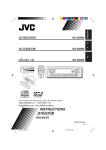
LOCATION OF THE BUTTONS
ENGLISH
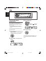
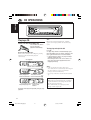
Control panel
Display window
1
2
3
4
5
6
7
8
9
p
q
w
e
r
t
y
u
i
o
;
(standby/on attenuator) button
SEL (select) button
FM/AM button
CD button
Loading slot
Display window
0 (eject) button
Remote sensor
• You can control this unit with an optionally
purchased remote controller.
EQ (equalizer) button
5 (up) button
¡ (fast-forward) button
Control dial
Number buttons
MO (monaural) button
SSM (Strong-station Sequential Memory)
button
RPT (repeat) button
RND (random) button
MODE button
DISP (display) button
4/¢
buttons
(control panel release) button
a ∞ (down) button
1 (reverse) button
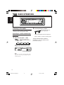
Display window
s Tuner reception indicators—MO (monaural),
ST (stereo)
d CD indicator
f RND
(random disc) indicator
g RPT (repeat) indicator
h LOUD (loudness) indicator
j EQ (equalizer) indicator
k Sound mode (C-EQ: custom equalizer)
indicators—ROCK, CLASSIC, POPS,
HIP HOP, JAZZ, USER
l Main display
/ Source display
Volume level indicator
4
EN02-04KD-G205[U]f.p65
4
10/7/03, 9:18 AM
ENGLISH
BASIC OPERATIONS
1
3
2
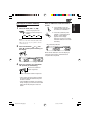
Turning on the power
1
4
Adjust the sound as you want.
(See pages 15 and 16.)
Turn on the power.
To drop the volume in a moment
Note on One-Touch Operation:
When you select a source in step 2 below, the
power automatically comes on. You do not have
to press this button to turn on the power.
2
Select the source.
Press
briefly while listening to any
source. “ATT” starts flashing on the display, and
the volume level will drop in a moment.
To resume the previous volume level, press the
button briefly again.
• If you turn the control dial, you can also restore
the sound.
To turn off the power
To operate the tuner (FM or AM),
see pages 8 – 11.
To play a CD,
see pages 12 – 14.
3
Adjust the volume.
To increase the volume
To decrease the volume
Volume level appears.
Press and hold
for more than one
second.
“SEE YOU” appears, then the unit turns off.
• If you turn off the power while listening to a
CD, CD play will start from where playback has
been stopped previously, next time you turn on
the power.
CAUTION on Volume Setting:
CDs produce very little noise compared with other
sources. If the volume level is adjusted for the
tuner, for example, the speakers may be damaged
by the sudden increase in the output level.
Therefore, lower the volume before playing a CD
and adjust it as required during playback.
Volume level indicator
5
EN05-07KD-G205[U]f.p65
5
9/26/03, 7:24 PM
ENGLISH
Canceling the display
demonstration
3
When shipped from the factory, display
demonstration has been activated, and starts
automatically when no operations are done for
about 20 seconds.
• It is recommended to cancel the display
demonstration before you use the unit for the
first time.
To cancel the display demonstration, follow
the procedure below:
1
Select “DEMO OFF.”
DEMO OFF
4
DEMO ON
Finish the setting.
Press and hold SEL (select) for more
than 2 seconds.
“DEMO,” “CLOCK H,” “CLOCK M,” “DIMMER,”
or “AMP GAIN” appears on the display.
To activate the display demonstration, repeat
the same procedure and select “DEMO ON” in
step 3.
2
Select “DEMO” if not shown on the
display.
6
EN05-07KD-G205[U]f.p65
6
9/26/03, 7:24 PM
ENGLISH
4
Setting the clock
1
Finish the setting.
Press and hold SEL (select) for more
than 2 seconds.
“DEMO,” “CLOCK H,” “CLOCK M,” “DIMMER,”
or “AMP GAIN” appears on the display.
To check the current clock time or change the
display mode
2
Press DISP (display) repeatedly.
Each time you press the button, the
display changes as follows:
Set the hour.
1 Select “CLOCK H” (hour) if not shown on
the display.
2 Adjust the hour.
1
2
• During tuner operation:
Frequency
Clock
• During CD operation:
Elapsed playing time
3
Set the minute.
1 Select “CLOCK M” (minute).
2 Adjust the minute.
1
Clock
• During power off:
The power turns on and the clock time is
shown for 5 seconds, then the power turns off.
2
7
EN05-07KD-G205[U]f.p65
7
9/26/03, 7:24 PM
ENGLISH
RADIO OPERATIONS
2
Listening to the radio
You can use either automatic searching or manual
searching to tune in to a particular station.
Searching for a station automatically:
Auto search
1
Start searching for a station.
To search for stations of
higher frequencies
To search for stations of lower frequencies
When a station is received, searching stops.
Select the band (FM1 – 3, AM).
Each time you press the
button, the band changes as
follows:
FM1
FM2
FM3
To stop searching before a station is
received, press the same button you have
pressed for searching.
AM
Lights up when receiving an FM stereo
broadcast with sufficient signal strength.
Selected band appears.
Note:
This receiver has three FM bands (FM1, FM2,
FM3). You can use any one of them to listen to
an FM broadcast.
8
EN08-11KD-G205[U]f.p65
8
9/26/03, 7:24 PM
1
1 Press MODE to enter the
Select the band (FM1 – 3, AM).
Each time you press the
button, the band changes as
follows:
FM1
FM2
FM3
AM
Note:
This receiver has three FM bands (FM1, FM2,
FM3). You can use any one of them to listen to
an FM broadcast.
2
When an FM stereo broadcast is hard to
receive
ENGLISH
Searching for a station manually:
Manual search
functions mode while listening
to an FM stereo broadcast.
2 Press MO (monaural), while
“MODE” is still flashing on the
display, so that “MONO”
appears on the display.
Each time you press the button,
monaural mode turns on and off
alternately.
MO (monaural) indicator
Press and hold ¢
or
4
until “M” (manual) starts flashing on
the display.
When the MO indicator is lit on the display, the
sound you hear becomes monaural but the
reception will be improved.
3
Tune in to a station you want while
“M” (manual) is still flashing.
To tune in to stations of
higher frequencies
To tune in to stations of lower frequencies
• If you release your finger from the button,
the manual mode will automatically turns
off after 5 seconds.
• If you hold down the button, the frequency
keeps changing (in 50 kHz intervals for FM
and 9 kHz for AM) until you release the
button.
9
EN08-11KD-G205[U]f.p65
9
9/26/03, 7:24 PM
ENGLISH
Storing stations in memory
You can use one of the following two methods to
store broadcasting stations in memory.
• Automatic preset of FM stations: SSM (Strongstation Sequential Memory)
• Manual preset of both FM and AM stations
Manual preset
You can preset up to 6 stations in each band
(FM1, FM2, FM3, and AM) manually.
Ex.: Storing FM station of 92.5 MHz into the
preset number 1 of the FM1 band.
1
FM station automatic preset: SSM
You can preset 6 local FM stations in each FM
band (FM1, FM2, and FM3).
1
FM1
2
3
Each time you press the
button, the band changes as
follows:
Select the FM band (FM1 – 3) you
want to store FM stations into.
Each time you press the
button, the band changes as
follows:
FM2
FM3
FM1
2
AM
FM2
FM3
AM
Tune in to a station (in this example,
of 92.5 MHz).
To tune in to stations of
higher frequencies
Press MODE to enter the functions
mode.
Press and hold SSM for about
2 seconds.
Select the band (FM1 – 3, AM) you
want to store stations into (in this
example, FM1).
To tune in to stations of lower frequencies
3
Press and hold the number button
(in this example, 1) for more than
2 seconds.
“SSM” flashes, then disappears when
automatic preset is over.
Local FM stations with the strongest signals are
searched and stored automatically in the band
number you have selected (FM1, FM2, or FM3).
These stations are preset in the number
buttons—No.1 (lowest frequency) to No.6
(highest frequency).
When automatic preset is over, the station stored
in number button 1 will be automatically tuned in.
Preset number flashes for a while.
10
EN08-11KD-G205[U]f.p65
10
9/26/03, 7:24 PM
Repeat the above procedure to store
other stations into other preset
numbers.
Notes:
• A previously preset station is erased when a new
station is stored in the same preset number.
• Preset stations are erased when the power supply to
the memory circuit is interrupted (for example,
during battery replacement). If this occurs, preset
the stations again.
Tuning in to a preset station
You can easily tune in to a preset station.
Remember that you must store stations first. If
you have not stored them yet, see “Storing
stations in memory” on pages 10 and 11.
1
ENGLISH
4
Select the band (FM1 – 3, AM).
Each time you press the
button, the band changes as
follows:
FM1
2
FM2
FM3
AM
Select the number (1 – 6) for the
preset station you want.
Note:
You can also use the 5 (up) or ∞ (down) button on
the unit to select the next or previous preset stations.
Each time you press the 5 (up) or ∞ (down) button,
the next or previous preset station is tuned in.
11
EN08-11KD-G205[U]f.p65
11
9/26/03, 7:24 PM
ENGLISH
CD OPERATIONS
Playing a CD
Insert a CD into the loading slot.
The unit turns on, draws
the CD and starts
playback automatically.
Note on One-Touch Operation:
When a CD is already in the loading slot, pressing
CD turns on the unit and starts playback
automatically.
CD indicator
Current source indication
Total playing time
Total track number
of the inserted disc of the inserted disc
Elapsed playing time
Current track
number
Note:
When a CD is inserted upside down, “EJECT”
appears on the display and the CD automatically
ejects.
To stop play and eject the CD
Press 0.
CD play stops and the CD automatically ejects
from the loading slot. The source changes to the
tuner (you will hear the last received station.)
• If you change the source, CD play also stops
(without ejecting the CD).
Next time you select “CD” as the source, CD
play starts from where playback has been
stopped previously.
Notes:
• If the ejected CD is not removed for about
15 seconds, the CD is automatically inserted again
into the loading slot to protect it from dust.
(CD play will not start this time.)
• You can eject the CD even when the unit is turned
off.
About mistracking:
Mistracking may result from driving on extremely
rough roads. This does not damage the unit and
the CD, but will be annoying.
We recommend that you stop CD play while
driving on such rough roads.
All tracks will be played repeatedly until you stop
playback.
12
EN12-14KD-G205[U]f.p65
12
9/26/03, 7:24 PM
To fast-forward or reverse the track
Press and hold ¡, while
playing a CD, to fast-forward the
track.
Press and hold 1, while playing a CD, to
reverse the track.
Selecting CD playback modes
To play back tracks at random
(Disc Random Play)
You can play back all tracks on the CD at random.
1 Press MODE to enter the
functions mode while playing a
CD.
2 Press RND (random), while
“MODE” is still flashing on the
display, so that “DISC RND”
appears on the display.
Each time you press the button,
disc random play mode turns on
and off alternately.
To go to the next or previous tracks
Press ¢
briefly, while
playing a CD, to go ahead to the
beginning of the next track.
Each time you press the button
consecutively, the beginning of
the next tracks is located and
played back.
Press
4 briefly, while playing a CD, to go
back to the beginning of the current track.
Each time you press the button consecutively,
the beginning of the previous tracks is located
and played back.
ENGLISH
Locating a track or a
particular portion on a CD
RND
(random disc) indicator
When disc random play is turned on, the
RND
indicator lights up on the display. A
track randomly selected starts playing.
To go to a particular track directly
Press the number button corresponding to the
track number to start its playback.
• To select a track number from 1 – 6:
Press 1 (7) – 6 (12) briefly.
• To select a track number from 7 – 12:
Press and hold 1 (7) – 6 (12) for more than one
second.
13
EN12-14KD-G205[U]f.p65
13
9/26/03, 7:24 PM
ENGLISH
To play back tracks repeatedly
(Track Repeat Play)
Prohibiting CD ejection
You can play back the current track repeatedly.
You can prohibit CD ejection and can lock a CD
in the loading slot.
1 Press MODE to enter the
functions mode while playing a
CD.
While pressing CD, press and hold 0 for
more than 2 seconds.
2 Press RPT (repeat), while
“MODE” is still flashing on the
display, so that “TRK RPT”
appears on the display.
Each time you press the button,
track repeat play mode turns on
and off alternately.
“NO EJECT” flashes on the display for about
5 seconds, and the CD is locked and cannot be
ejected.
RPT indicator
When track repeat play is turned on, the RPT
indicator lights up on the display. The current
track starts playing repeatedly.
To cancel the prohibition and unlock the
CD
While pressing CD, press and hold 0 again for
more than 2 seconds.
“EJECT” appears on the display, and the CD
ejects from the loading slot.
14
EN12-14KD-G205[U]f.p65
14
9/26/03, 7:24 PM
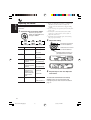
Selecting preset sound modes
(C-EQ: custom equalizer)
Indication
For:
Preset values
BAS
TRE
LOUD
USER
(Flat sound)
00
00
OFF
You can select a preset sound mode (C-EQ:
custom equalizer) suitable to the music genre.
ROCK
Rock or
disco music
+03
+01
ON
Select the sound mode you want.
CLASSIC
Classical
music
+01
–02
OFF
POPS
Light music
+04
+01
OFF
HIP HOP
Funk or rap
music
+02
00
ON
JAZZ
Jazz music
+02
+03
OFF
Each time you press the
button, the sound modes
change as follows:
USER
JAZZ
ROCK
CLASSIC
HIP HOP
POPS
ENGLISH
SOUND ADJUSTMENTS
Note:
You can adjust each sound mode to your preference.
Once you make an adjustment, it is automatically
stored for the currently selected sound mode. See
“Adjusting the sound” on page 16.
Indication pattern changes for each
sound mode except for “USER.”
Ex.: When you select “ROCK”
15
EN15-16KD-G205[U]f.p65
15
9/26/03, 7:24 PM
ENGLISH
Adjusting the sound
*1 When you adjust the bass, treble, or loudness, the
You can adjust the sound characteristics to your
preference.
1
Select the item you want to adjust.
Each time you press the
button, the adjustable items
change as follows:
BAS
TRE
(bass)
(treble)
VOL
LOUD
BAL
(loudness)
(balance)
To do:
Adjust the setting.
To increase the level or
turn on the loudness
Range
Adjust the bass.
To decrease the level or
turn off the loudness
–06 (min.)
|
+06 (max.)
1
TRE*
Adjust the treble.
–06 (min.)
|
+06 (max.)
FAD*2
Adjust the front
and rear speaker
balance.
R06 (Rear only)
|
F06 (Front only)
BAL
Adjust the left
and right speaker
balance.
L06 (Left only)
|
R06 (Right only)
LOUD*1
Boost low and high
frequencies to
LOUD ON
produce a well|
balanced sound
LOUD OFF
at low volume
level.
VOL*3
2
(fader)
(volume)
Indication
BAS*1
FAD
adjustment you have made is stored for the
currently selected sound mode (C-EQ) including
“USER.”
*2 If you are using a two-speaker system, set the fader
level to “00.”
*3 Normally the control dial works as the volume
control. So you do not have to select “VOL” to
adjust the volume level.
*4 Depending on the amplifier gain control setting.
(See page 17 for details.)
Adjust the volume. 00 (min.)
|
30 or 50 (max.)*4
Indication pattern changes as
you adjust the bass or treble.
Ex. 1: When you adjust “TRE” (treble)
Ex. 2: When you turn on the loudness
3
Repeat steps 1 and 2 to adjust the
other items.
To reset each sound mode to the factory
settings, repeat the same procedure and
reassign the preset values listed in the table on
page 15.
16
EN15-16KD-G205[U]f.p65
16
9/26/03, 7:24 PM
Selecting the dimmer mode
You can dim the display at night (according to
your preference).
When shipped from the factory, dimmer is
deactivated.
1
Press and hold SEL (select) for more
than 2 seconds.
“DEMO,” “CLOCK H,” “CLOCK M,” “DIMMER,”
or “AMP GAIN” appears on the display.
Selecting the amplifier gain
control
You can change the maximum volume level of
this unit. When the maximum power of the
speakers is less than 50 W, select “LOW PWR”
to prevent them from being damaged.
When shipped from the factory, “HIGH PWR” is
selected.
1
ENGLISH
OTHER MAIN FUNCTIONS
Press and hold SEL (select) for more
than 2 seconds.
“DEMO,” “CLOCK H,” “CLOCK M,” “DIMMER,”
or “AMP GAIN” appears on the display.
2
Select “DIMMER” if not shown on
the display.
2
3
Select “AMP GAIN” if not shown on
the display.
Select the desired mode—“OFF” or
“ON.”
3
Select the desired mode—
“HIGH PWR” or “LOW PWR.”
• OFF: Cancels the dimmer.
• ON: Activates the dimmer.
4
• LOW PWR: You can adjust the volume level
from “VOL 00” to “VOL 30.”
• HIGH PWR: You can adjust the volume level
from “VOL 00” to “VOL 50.”
Finish the setting.
4
Finish the setting.
Note:
If you change the setting from “HIGH PWR” to
“LOW PWR” while listening at a volume level more
than 30, the unit automatically changes the volume
level to “VOL 30.”
EN17-18KD-G205[U]f.p65
17
9/26/03, 7:25 PM
17
ENGLISH
Detaching the control panel
You can detach the control panel when leaving
the car.
When detaching or attaching the control panel,
be careful not to damage the connectors on the
back of the control panel and on the panel
holder.
Attaching the control panel
1
Insert the left side of the control
panel into the groove on the panel
holder.
Detaching the control panel
Before detaching the control panel, be sure to
turn off the power.
1
2
3
Unlock the control panel.
Lift and pull the control panel out of
the unit.
2
Press the right side of the control
panel to fix it to the panel holder.
Note on cleaning the connectors:
If you frequently detach the control panel, the
connectors will deteriorate.
To minimize this possibility, periodically wipe the
connectors with a cotton swab or cloth moistened
with alcohol, being careful not to damage the
connectors.
Put the detached control panel into
the provided case.
Connectors
18
EN17-18KD-G205[U]f.p65
18
9/26/03, 7:25 PM
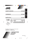
USING THE REMOTE CONTROLLER
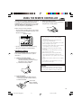
3. Return the battery holder.
Insert again the battery holder by pushing it
until you hear a clicking sound.
(back side)
ENGLISH
This unit can be remotely controlled as instructed
here (with an optionally purchased remote
controller). We recommend that you use remote
controller RM-RK50 or RM-RK60 with your unit.
(Ex.: When you are using RM-RK60)
Before using the remote controller:
• Aim the remote controller directly at the remote
sensor on the main unit. Make sure there is no
obstacle in between.
Remote sensor
• Do not expose the remote sensor to strong
light (direct sunlight or artificial lighting).
Installing the battery
When the controllable range or effectiveness
of the remote controller decreases, replace
the battery.
1. Remove the battery holder.
1) Push out the battery holder in the
direction indicated by the arrow using a
ball point pen or a similar tool.
2) Remove the battery holder.
WARNING:
• Store the battery in a place where children
cannot reach.
If a child accidentally swallows the battery,
consult a doctor immediately.
• Do not recharge, short, disassemble, or heat the
battery or dispose of it in a fire.
Doing any of these things may cause the battery
to give off heat, crack, or start a fire.
• Do not leave the battery with other metallic
materials.
Doing this may cause the battery to give off
heat, crack, or start a fire.
• When throwing away or saving the battery,
wrap it in tape and insulate; otherwise, the
battery may start to give off heat, crack, or start
a fire.
• Do not poke the battery with tweezers or similar
tools.
Doing this may cause the battery to give off
heat, crack, or start a fire.
CAUTION:
DO NOT leave the remote controller in a place
(such as dashboards) exposed to direct sunlight
for a long time. Otherwise, it may be damaged.
(back side)
2. Place the battery.
Slide the battery into the holder with the
+ side facing upwards so that the battery
is fixed in the holder.
Lithium coin
battery (product
number: CR2025)
19
EN19-20KD-G205[U]f.p65
19
9/26/03, 7:25 PM
ENGLISH
Location of the buttons
RM-RK60
3 Selects the preset stations while listening to
the radio.
Each time you press the button, the preset
station number increases, and the selected
station is tuned in.
4 Selects the sound mode (C-EQ: custom
equalizer).
Each time you press the button, the sound
mode (C-EQ) changes.
5 Selects the band while listening to the radio.
Each time you press the button, the band
changes.
S
6 Selects the source.
Each time you press the button, the source
changes.
7 Functions the same as the control dial on the
main unit.
Note: These buttons are not used for adjusting
“DEMO,” “CLOCK H,” “CLOCK M,”
“DIMMER,” and “AMP GAIN” (see pages
6, 7 and 17).
1 • Turns on the unit if pressed when the unit is
turned off.
• Turns off the unit if pressed and held until
“SEE YOU” appears on the display.
• Drops the volume level in a moment if
pressed briefly.
Press again to resume the volume.
2 • Searches for stations while listening to the
radio.
• Fast-forwards or reverses the track if
pressed and held while listening to a CD.
• Skips to the beginning of the next track or
goes back to the beginning of the current (or
previous) tracks if pressed briefly while
listening to a CD.
20
EN19-20KD-G205[U]f.p65
20
9/26/03, 7:25 PM
What appears to be trouble is not always serious. Check the following points before calling a service
center.
Symptoms
Causes
The volume level is set to the
minimum level.
Adjust it to the optimum level.
Connections are incorrect.
Check the cords and
connections.
• This unit does not work at
all.
The built-in microcomputer
may have functioned
incorrectly due to noise, etc.
While holding SEL (select),
press
(standby/on
attenuator) for more than
2 seconds to reset the unit. (The
clock setting and preset stations
stored in memory are erased.)
(See page 2.)
• SSM (Strong-station
Sequential Memory)
automatic preset does not
work.
Signals are too weak.
Store stations manually.
• Static noise while listening
to the radio.
The antenna is not connected
firmly.
Connect the antenna firmly.
• CD automatically ejects.
CD is inserted upside down.
Insert the CD correctly.
• CD-R/CD-RW cannot be
CD-R/CD-RW is not finalized.
played back.
• Tracks on the CD-R/CD-RW
cannot be skipped.
• Insert a finalized CD-R/
CD-RW.
• Finalize the CD-R/CD-RW
with the component which
you used for recording.
• CD can be neither played
back nor ejected.
CD is locked.
Unlock the CD.
(See page 14.)
The CD player may have
functioned incorrectly.
While holding
(standby/on attenuator), press
0 (eject) for more than
2 seconds. Be careful not to
drop the CD when it is ejected.
You are driving on rough
roads.
Stop playback while driving on
rough roads.
CD is scratched.
Change the CD.
Connections are incorrect.
Check the cords and
connections.
No CD in the loading slot.
Insert a CD into the loading slot.
CD is inserted incorrectly.
Insert the CD correctly.
CD Playback
FM/AM
General
• Sound cannot be heard
from the speakers.
Remedies
• CD sound is sometimes
interrupted.
• “NO DISC” appears on the
display.
ENGLISH
TROUBLESHOOTING
21
EN21-23KD-G205[U]f.p65
21
9/26/03, 7:25 PM
ENGLISH
MAINTENANCE
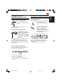
Handling discs
When playing a CD-R or CD-RW
This unit has been designed to reproduce CDs,
CD-Rs (Recordable), and CD-RWs (Rewritable).
• This unit is not compatible with MP3 discs.
How to handle discs
When removing a disc
Center holder
from its case, press down
the center holder of the case
and lift the disc out, holding
it by the edges.
• Always hold the disc by the edges. Do not
touch its recording surface.
When storing a disc into its case, gently insert
the disc around the center holder (with the
printed surface facing up).
• Make sure to store discs into the cases after
use.
To keep discs clean
A dirty disc may not be played
correctly. If a disc does become
dirty, wipe it with a soft cloth in a
straight line from center to edge.
To play new discs
New discs may have some rough
spots around the inner and outer
edges. If such a disc is used, this
unit may reject the disc.
To remove these rough spots, rub the edges with
a pencil or ball-point pen, etc.
Moisture condensation
Moisture may condense on the lens inside the
CD player in the following cases:
• After starting the heater in the car.
• If it becomes very humid inside the car.
Should this occur, the CD player may
malfunction. In this case, eject the disc and leave
the unit turned on for a few hours until the
moisture evaporates.
Sticker
Warped
disc
Before playing back CD-Rs or CD-RWs, read
their instructions or cautions carefully.
• Use only “finalized” CD-Rs or CD-RWs.
• Some CD-Rs or CD-RWs may not be played
back on this unit because of their disc
characteristics, and for the following reasons:
– Discs are dirty or scratched.
– Moisture condensation on the lens inside the
unit.
– The pickup lens inside the unit is dirty.
• CD-RWs may require a longer readout time
since the reflectance of CD-RWs is lower than
that of regular CDs.
• CD-Rs or CD-RWs are susceptible to high
temperatures or high humidity, so do not leave
them inside your car.
• Do not use following CD-Rs or CD-RWs:
– Discs with stickers, labels, or protective seal
stuck to the surface.
– Discs on which labels can be directly printed
by an ink jet printer.
Using these discs under high temperatures or
high humidity may cause malfunctions or
damage to discs. For example,
– Stickers or labels may shrink and warp a
disc.
– Stickers or labels may be peeled off so discs
cannot be ejected.
– Print on discs may get sticky.
Read instructions or cautions about labels and
printable discs carefully.
CAUTIONS:
• Do not insert 8 cm discs (single CDs) into the
loading slot. (Such discs cannot be ejected.)
• Do not insert any disc of unusual shape—like a
heart or flower; otherwise, it will cause a
malfunction.
• Do not expose discs to direct sunlight or any
heat source or place them in a place subject to
high temperature and humidity. Do not leave
them in a car.
• Do not use any solvent (for example,
conventional record cleaner, spray, thinner,
benzine, etc.) to clean discs.
Sticker
residue
Disc
22
EN21-23KD-G205[U]f.p65
22
9/26/03, 7:25 PM
Stick-on
label
AUDIO AMPLIFIER SECTION
CD PLAYER SECTION
Maximum Power Output:
Front:
50 W per channel
Rear:
50 W per channel
Continuous Power Output (RMS):
Front:
19 W per channel into 4 Ω, 40 Hz
to 20 000 Hz at no more than
0.8% total harmonic distortion.
Rear:
19 W per channel into 4 Ω, 40 Hz
to 20 000 Hz at no more than
0.8% total harmonic distortion.
Load Impedance: 4 Ω (4 Ω to 8 Ω allowance)
Tone Control Range:
Bass:
±10 dB at 100 Hz
Treble: ±10 dB at 10 kHz
Frequency Response: 40 Hz to 20 000 Hz
Signal-to-Noise Ratio: 70 dB
Line-Out Level/Impedance:
2.0 V/20 kΩ load (full scale)
Output Impedance: 1 kΩ
Type: Compact disc player
Signal Detection System: Non-contact optical
pickup (semiconductor laser)
Number of channels: 2 channels (stereo)
Frequency Response: 5 Hz to 20 000 Hz
Dynamic Range:
96 dB
Signal-to-Noise Ratio: 98 dB
Wow and Flutter: Less than measurable limit
TUNER SECTION
Frequency Range:
FM:
87.5 MHz to 108.0 MHz
AM:
531 kHz to 1 602 kHz
[FM Tuner]
Usable Sensitivity:
11.3 dBf (1.0 µV/75 Ω)
50 dB Quieting Sensitivity:
16.3 dBf (1.8 µV/75 Ω)
Alternate Channel Selectivity (400 kHz):
65 dB
Frequency Response: 40 Hz to 15 000 Hz
Stereo Separation: 35 dB
Capture Ratio: 1.5 dB
ENGLISH
SPECIFICATIONS
GENERAL
Power Requirement:
Operating Voltage:
DC 14.4 V (11 V to 16 V allowance)
Grounding System: Negative ground
Allowable Operating Temperature: 0°C to +40°C
Dimensions (W × H × D):
Installation Size (approx.):
182 mm × 52 mm × 150 mm
Panel Size (approx.):
188 mm × 58 mm × 11 mm
Mass (approx.):
1.3 kg (excluding accessories)
Design and specifications are subject to change
without notice.
[AM Tuner]
Sensitivity: 20 µV
Selectivity: 35 dB
Having TROUBLE with operation?
Please reset your unit
Refer to page of How to reset your unit
23
EN21-23KD-G205[U]f.p65
23
9/26/03, 7:25 PM
CDqÒGA l u¹œ«—
wd
KD-G205
Æ∂ W×H# dE½« ¨÷«dF²Ýô« WHOþË ¡UGô Æ÷dF« WýUA ÷«dF²Ý« WHOþuÐ œË
Ò e “UN'« «c¼ •
ÆqBHM*« ULOKF²« VO² WFł«d vłd¹ ¨ öOu²«Ë VOd²« UOKLF
ULOKF²« VO²
EN, CT, TH, AR
1003KKSMDTJEIN
© 2003 VICTOR COMPANY OF JAPAN, LIMITED
CoverKD-G205[U]-Araf
2
6/10/03, 9:55 AM
KD-G205
Installation/Connection Manual
!"#$
°“√µ‘¥µ—Èß/§ŸË¡◊Õ°“√µ‘¥µ—Èß
GET0186-003A
[U]
1003KKSMDTJEIN
EN, CT, TH, AR
qOu²«ØVOd²« ULOKFð VÒO²
ENGLISH
This unit is designed to operate on 12 V DC,
NEGATIVE ground electrical systems. If your
vehicle does not have this system, a voltage
inverter is required, which can be purchased at
JVC car audio dealers.
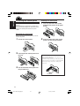
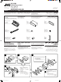
Parts list for installation and
connection
!"#$% 1 2 V !"#$%&'
!"#$%&'()*+,-./'0(
!"#$% JVC !"#$%&'(
The following parts are provided for this unit.
After checking them, please set them correctly.
wÐdŽ
‰∑¬
!"#$%&'(
√“¬°“√ Ë«πª√–°Õ∫ ”À√—∫µ‘¥µ—Èß·≈–‡™◊ËÕ¡µËÕ°—π
!"#$%&'()
!"#$%&'()*
A/B
Hard case/Control panel
!"#
—UOð WDÝ«uÐ jI qLFO “UN'« «c¼ rL bI
WOzUÐdN WLE½« ¨Xu ±≤ ¨DC dýU³% wzUÐdN
«c¼ q¦% œułË ÂbŽ WUŠ w ÆVUÝ i¹—Qð
‰u×% «b<²Ý« V−¹ ¨pð—UOÝ w ÂUEM«
…eNłô« ¡öË s% ‰u;« «c¼ ¡«dý sJ1Ë ¨ÃU²u
ÆJVC W—U% «—UOJK WOðuB«
™ÿ¥ª√–°Õ∫π’È ‰¥È√—∫°“√ÕÕ°·∫∫¡“‡æ◊ËÕ„™Èß“π°—∫√–∫∫
°√–· ‰øøÈ“ “¬¥‘π¢—È«≈∫°√–· µ√ß 12 ‚«≈∑Ï
À“°√∂¬πµÏ¢Õߧÿ≥‰¡Ë ‰¥È „™È√–∫∫π’È
µÈÕß„™È‡§√◊ËÕß·ª≈ß°√–· ‰ø™Ë«¬
´÷Ëß “¡“√∂À“´◊ÈÕ‰¥È®“°√È“π¢“¬‡§√◊ËÕ߇ ’¬ß√∂¬πµÏ JVC
qOu²«Ë VOd²« ¡«eł« WLzUK
Ë«πª√–°Õ∫µËÕ‰ªπ’È„ÀÈ¡“°—∫™ÿ¥ª√–°Õ∫π’È À≈—
ß®“°µ√«® Õ∫·≈È« ª√—∫µ—È߇§√◊ËÕß„ÀÈ∂Ÿ°µÈÕß
Æ“UN'« l% …œËe% WOU²« ¡«ełô«
qJAÐ rN³Odð vłd¹ ¨¡«ełô« Ác¼ h× bFÐ
Æ`O×
C
Sleeve
!
D
Trim plate
≈—ß∫√√®ÿ/ÀπÈ“ª—¥
ª≈Õ°Àÿ¡È
·ºËπ‚≈À–¢Õ∫·µËß
rJײ« WŠuØVK ‚ËbM
wK«u« qJON«
WM¹e« WŠu
E
Power cord
!"#$%&
F
Washer (ø5)
=Eø5F
©µ dDK® qOu²« ÂUJŠ« WIKŠ
G
Lock nut (M5)
!=EM5F
πÕµ≈ÁÕ§ (M5)
©M5® XO³¦²« WuL
I
Rubber cushion
!"
J
Handles
!"
“¬‡§‡∫‘≈°”≈—ß
ª√–‡°Áπ«ß·À«π (ø5)
WOzUÐdNJ« WKUD« pKÝ
H
Mounting bolt (M5 x 20 mm)
!=EM5 x 20 mmF
≈—°µ‘¥ (M5 x 20 ¡‘≈≈‘‡¡µ√)
©r?K% ≤∞ x M5® VOd²« —ULJ%
§—π∫—ߧ—∫
¬“ß°—π°√–·∑°
UUJ*«
WOÞUD*« …uA(«
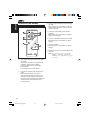
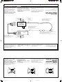
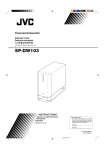
INSTALLATION
(IN-DASH MOUNTING)
!"#$%&
!
The following illustration shows a typical
installation. If you have any questions or require
information regarding installation kits, consult
your JVC car audio dealer or a company
supplying kits.
• If you are not sure how to install this unit
correctly, have it installed by a qualified
technician.
!"#$%&'()*+,-./
!"#$%&'()*+,- JVC !"#$%&'()*+,-./
• !"#$%&#'()*+,-./
!"#$%&'
uKÐUð ‡ qš«œ ® “UN'« VOdð
°“√µ‘¥µ—ßÈ (°“√ª√–°Õ∫·ºßÀπÈ“ª—∑¡Ï‡¢È“)
©…—UOJ«
¿“æµ—«Õ¬Ë“ßµËÕ‰ªπ’È· ¥ß∂÷ß°“√µ‘¥µ—Èß·∫∫∑—Ë«‰ª À“°§ÿ≥¡’ª—
≠À“À√◊ÕµÈÕß°“√¢ÈÕ¡Ÿ≈‡°’ˬ«°—∫™ÿ¥µ‘¥µ—Èß °√ÿ≥“ª√÷°…“°—
∫ºŸÈ¢“¬‡§√◊ËÕ߇ ’¬ß√∂¬πµÏ JVC ¢Õß∑Ë“πÀ√◊Õ∫√‘…—
• ™ÿ¥ª√–°Õ∫ ∂È“§ÿ≥‰¡Ë·πË„®«Ë“µ‘¥µ—Èß™ÿ¥ª√–°Õ∫π’È∂Ÿ°µÈÕßÀ√◊Õ‰¡Ë
„ÀÈÀ“™Ë“ߺŸÈ‡™’ˬ«™“≠‡ªÁπºŸÈµ‘¥µ—Èß
4
2
1
VOd²« WI¹dÞ wU²« w×O{u²« rÝd« sO³¹
Ò
WłUŠ Ë« «—UJH²Ý« „UM¼ ÊU «–« ÆWOU¦*«
vłd¹ ¨VOd²« «Ëœ« ’uB<Ð U%uKF*
«—UOJK WOðuB« …eNłô« Ÿ“u% …—UA²Ý«
Æ «Ëœô« …cN WŽ“u*« WdA« Ë« JVC W—U%
“UN'« VOdð WOHOJÐ p²dF% ÂbŽ WUŠ w •
“UN'« VOdð WOKLŽ „dð vłd¹ ¨`O× qJAÐ
Ác¼ q¦% VOd² q¼R%Ë h²<% h<A
Æ…eNłô«
3
B
Do the required electrical connections.
!"#$%&'
D
µËÕ “¬‰øµ“¡∑’Ë°”À𥉫È∑—ÈßÀ¡¥
ÆWÐuKD*« WOzUÐdNJ« öOu²« qLŽ«
I
18
4
m
m
53
C
3
J
4
*1 When you stand the unit, be
careful not to damage the fuse
on the rear.
*1 !"#$%&'()*
!"#
*1 ‡¡◊ËÕ§ÿ≥µ—Èß™ÿ¥ª√–°Õ∫¢÷Èπ √–«—
C
*1
5
6
D
B
1
Instal1-2_KD-G205[U]_4
1
6/10/03, 10:35 PM
m
m
2
H
Bend the appropriate tabs to hold the
sleeve firmly in place.
!"#$%&'( !)*+
ßլ˓∑”„ÀÈø«‘ Ï∫√‘‡«≥ Ë«π∑È“¬‡ ’¬À“¬
qł« s% t³²½« ¨“UN'« nOKuð bMŽ ±*
vKŽ œułu*« “uOH« —dCð ÂbŽ
ÆWOHK)« WN'«
1
ßÕ·ºËπ‡æ◊ËÕ¬÷¥ª≈Õ°„ÀȵËÕ°—π‡¢È“∑’Ë
XO³¦² VÝUM% qJAÐ WMJô« w¦½«
ÊUJ*« w rJ×% qJAÐ wK«u« qJON«
Æ`O×B«
Removing the unit
Before removing the unit, release the rear
section.
!"#$%&!"'()*+,-.(/0
1
!
°“√∂Õ¥™ÿ¥ª√–°Õ∫
2
…—UOJ« uKÐUð s% “UN'« Ÿe½
°ËÕπ®–∂Õ¥™ÿ¥ª√–°Õ∫ „ÀȪ≈¥ÀπÈ“µ—¥ Ë«π∑È“¬°ËÕπ
ÆwHK)« ¡e'« —dŠ ¨“UN'« Ÿe½ q³K
3
B
Insert the two handles, then pull them as illustrated so that
the unit can be removed.
!"#$%&'()*+,-."/01234$5
!"#$%&'() *+
D
„ ˧π— ∫—ߧ—∫ 2 Õ—π≈ß„π√ËÕß ”À√—∫„™Èæπ— ≈«¥ ¥—ß¿“æ ®“°π—πÈ „Àȇ≈◊ÕË π™ÿ¥ª√–°Õ∫ÕÕ° „π¢≥–
∑’˧ËÕ¬ Ê ¥÷ߧ—π∫—ߧ—∫∑—Èß Õß Õ—πÕÕ°®“°°—π
J
sJ1 YO×Ð sÒO³% u¼ UL rN³×Ý« p– bFÐË ¨5²UJ*« qšœ«
Æ“UN'« Ÿe½
When using the optional stay
!"#
When installing the unit without using the sleeve
!"#$%&'($
‡¡◊ËÕ„™Èµ—«¬÷¥·∫∫‡≈◊Õ°‰¥È (“¡“√∂‡≈◊Õ°‡ª‘¥§È“߉«È ‰¥È)
‡¡◊ËÕµ‘¥µ—Èß™ÿ¥ª√–°Õ∫‚¥¬‰¡Ë „™Èª≈Õ°ÀÿÈ¡
WOU{ô« W%UŽb« «b<²Ý« bMŽ
wK«u« qJON« «b<²Ý« ÊËbÐ “UN'« Vdð U%bMŽ
In a Toyota for example, first remove the car radio and install the unit in its place.
!"TOYOTA !"#$%&' ()*+,-./*0123'4567
µ—«Õ¬Ë“߇™Ëπ „π√∂¬πµÏ‚µ‚¬µÈ“ „ÀÈ∂Õ¥«‘∑¬ÿµ‘¥√∂¬πµÏÕÕ°°ËÕπ·≈–µ‘¥µ—Èß™ÿ¥ª√–°Õ∫π’ȇ¢È“‰ª·∑π
Stay (option)
!"
Æt½UJ% w “UN'« VÒ— p– bFÐ ôË« …—UOJ« u¹œ«— Ÿe½« ¨Uðu¹uð Ÿu½ «—UOÝ w ¨‰U¦*« qO³Ý vKŽ
µ—«¬÷¥ (‡≈◊Õ°‰¥È)
Flat type screws (M5 x 8 mm)*
EM5 x 8 mmF*
©WOU{«® W%UŽb«
°√ŸÀ—«‡√’¬∫ (M5 x 8 ¡‘≈≈‘‡¡µ√)*
*©rK% ∏ x M5® …bŽUI« W¹u²J% wž«dÐ
Fire wall
* Not included with this unit
* !"#$
ºπ—ß°—π‰ø
s% W¹UL(« —«bł
o¹d(«
*
‰¡Ë ‰¥È„ÀÈ¡“°—∫™ÿ¥ª√–°Õ∫π
“UN'« «c¼ l% œÒËe% dOž *
F
G
H
Bracket*
*
Dashboard
·∑Ëπ√Õß√—∫*
*XO³¦²« WOH²
·ºßÀπÈ“ª—∑¡Ï
…—UOJ« uKÐUð
Flat type screws (M5 x 8 mm)*
! EM5 x 8 mmF*
°√ŸÀ—«‡√’¬∫ (M5 x 8 ¡‘≈≈‘‡¡µ√)*
*©rK% ∏ x M5® …bŽUI« W¹u²J% wž«dÐ
Screw (option)
!"#$
C
°√Ÿ (‡≈◊Õ°‰¥È)
Pocket
©wU{«® wždÐ
Bracket*
*
°–‡ª“–
VOł
Note
Install the unit at an angle of less than 30˚.
!"#$% 30° !
µ‘¥µ—ßÈ ™ÿ¥ª√–°Õ∫∑’¡Ë ¡ÿ µË”°«Ë“ 30 Õß»“
Wł—œ ≥∞ s% qK« W¹Ë«“ vKŽ “UN'« V—
Ò
TROUBLESHOOTING
À¡“¬‡Àµ
·∑Ëπ√Õß√—∫*
*XO³¦²« WOH²
: When installing the unit on the mounting bracket, make sure to use the 8 mm-long screws. If
longer screws are used, they could damage the unit.
: !"#$%&'()*+,=8 mm= !"#$%&' !"()*+,-#
: ‡¡◊ËÕµ‘¥µ—Èß™ÿ¥ª√–°Õ∫≈ß„π·∑Ëπ√Õß√—∫‰«È „ÀÈ„™È °√Ÿ¬“«¢π“¥ 8 ¡‘≈≈‘‡¡µ√ ∂È“„™È °√Ÿ¬“«°«Ë“π’ÈÕ“®∑”„ÀÈ™ÿ¥ª√–°Õ∫‡ ’¬À“¬‰¥ô
s% ‰uÞ« wž«dР«b<²Ý« WUŠ w ÆrK% ∏ ‰uÞ wž«dÐ ‰ULF²Ý« s% bQð ¨VOd²« UOH² vKŽ “UN'« VOdð bMŽ ∫WEŠö%
Æ“UN−K —d{ Ë« nKð p– V³J¹ Ê« sJ1 ¨rK% ∏
!
°“√µ√«® Õ∫ª—≠À“¢—¥¢ÈÕß
• The fuse blows.
* Are the red and black leads connected
correctly?
• !"#
* !"#$%&'!"#$%()$*+
• Power cannot be turned on.
* Is the yellow lead connected?
• * !"#$
!"#$%&'$()
• No sound from the speakers.
* Is the speaker output lead short-circuited?
• * !"#$
!"#$%&'()*+,-
• Sound is distorted.
* Is the speaker output lead grounded?
* Are the “–” terminals of L and R speakers
grounded in common?
• !"
* !"#$%&'()*+
* !"#$%L !R
– !"#$%
• Noise interfere with sounds.
* Is the rear ground terminal connected to the
car’s chassis using shorter and thicker cords?
• * • Unit becomes hot.
* Is the speaker output lead grounded?
* Are the “–” terminals of L and R speakers
grounded in common?
• !"
* !"#$%&'()*+
* !"#$%L !R
– !"#$\
•
*
•
*
•
*
•
*
*
!"#
•
*
!"#
!"#$%&'()*+,*-./0
•
*
*
ø‘« Ï¢“¥
¡’°“√‡™◊ÕË ¡ “¬µ–°—«Ë ’¥”·≈– ’·¥ßլ˓ß∂Ÿ°µÈÕßÀ√◊Õ‰¡Ë
‰¡Ë “¡“√∂‡ª‘¥‡§√◊ËÕ߉¥È
¡’°“√‡™◊ËÕ¡ “¬µ–°—Ë« ’‡À≈◊ÕßÀ√◊Õ‰¡Ë
‰¡Ë¡’‡ ’¬ßÕÕ°®“°≈”‚æß
“¬µ–°—Ë« Ë«π∑’ËÕÕ°∑“ß≈”‚æ߇°‘¥‰øøÈ“≈—¥«ß®√À√◊Õ‰¡Ë
‡ ’¬ß‡æ’Ȭπ
“¬µ–°—Ë« Ë«π∑’ËÕÕ°∑“ß≈”‚æßµËÕ≈ߥ‘πÀ√◊Õ‰¡Ë
“¬¢—«È ≈∫ ¢Õß≈”‚æߥȓπ´È“¬·≈–¢«“µËÕ≈ߥ‘πµ“¡ª°µ‘À√◊Õ‰¡Ë
‡ ’¬ß√∫°«π
¡’°“√„™È “¬ —ÈπÊ À√◊ÕÀπ“Ê µËÕ®“°‡§√◊ËÕß Ë«π∑’˵‘¥µ—Èß
‰«È∫πæ◊Èπ¥È“πÀ≈—ß°—∫µ—«∂—ß√∂¬πµÏÀ√◊Õ‰¡Ë?
™ÿ¥ª√–°Õ∫√ÈÕπ¢÷Èπ
“¬µ–°—Ë« Ë«π∑’ËÕÕ°∑“ß≈”‚æßµËÕ≈ߥ‘πÀ√◊Õ‰¡Ë
“¬¢—«È ≈∫ ¢Õß≈”‚æߥȓπ´È“¬·≈–¢«“µËÕ≈ߥ‘πµ“¡ª°µ‘À√◊Õ‰¡Ë
!"#
2
Instal1-2_KD-G205[U]_f
2
9/10/03, 9:56 AM
Õöô«Ë ‰UDŽô« sŽ Y׳«
Æ“uOH« ‚d²×¹ •
qJAÐ Wuu% œuÝô«Ë dLŠô« pKJ« q¼ *
ø`O×
ÆWOzUÐdNJ« WKUD« qOuð sJ1 ô •
øôuu% dHô« pKJ« q¼ *
Æ UŽULJ« s% u —bB¹ ô •
Ãdš pKÝ …dz«œ w dOBIð pUM¼ q¼ *
øWŽULJ«
ÆÁuA% uB« •
ø÷—ôUÐ ôuu% WŽULJ« Ãdš pKÝ q¼ *
L ÈdJO« WŽULJK “≠” W³UJ« ·«dÞô« q¼ *
øiFÐ l% ÷—ôUÐ Wuu% R vMLO«Ë
Æ «uô« l% ZO−{ qš«bð
qJO¼ l% ‰uu% wHK)« w{—ô« ·dÞ q¼
øpLÝ«Ë dBK« „öÝ« ‰ULF²ÝUÐ …—UOJ«
Æ“UN'« s<J¹
ø÷—ôUÐ ôuu% WŽULJ« Ãdš pKÝ q¼
L ÈdJO« WŽULJK “≠” W³UJ« ·«dÞô« q¼
øiFÐ l% ÷—ôUÐ Wuu% R vMLO«Ë
•
*
•
*
*
ENGLISH
wÐdŽ
‰∑¬
ELECTRICAL CONNECTIONS
!
To prevent short circuits, we recommend that
you disconnect the battery’s negative terminal
and make all electrical connections before
installing the unit.
• Be sure to ground this unit to the car’s
chassis again after installation.
!"#$%&'()*+,#-./01
!"#$%&'()*+
• !"#$%&'()*+,-./01
‡æ◊ËÕªÈÕß°—π°“√‡°‘¥‰øøÈ“≈—¥«ß®√ ¢Õ·π–π”„ÀȪ≈¥¢—È«·∫µ‡µÕ√’Ë≈∫ÕÕ°
·≈È«®÷ßµËÕ “¬‰ø°ËÕ𵑥µ—È߇§√◊ËÕß
• µ√«® Õ∫„ÀÈ·πË „®«Ë“‰¥È‡¥‘𠓬¥‘πµËÕ√–À«Ë“߇§√◊ÕË ß°—∫µ—«∂—ß
√∂¬πµÏ „À¡Ë·≈È«À≈—ß®“°µ‘¥µ—ßÈ
Notes:
• Replace the fuse with one of the specified
rating. If the fuse blows frequently, consult
your JVC car audio dealer.
• It is recommended to connect to the speakers
with maximum power of more than 50 W (both
at the rear and at the front, with an impedance
of 4 Ω to 8 Ω). If the maximum power is less
than 50 W, change “AMP GAIN” setting to
prevent the speakers from being damaged
(see page 17 of the INSTRUCTIONS).
• To prevent short-circuit, cover the terminals of
the UNUSED leads with insulating tape.
• The heat sink becomes very hot after use. Be
careful not to touch it when removing this
unit.
• !"#$%&'()* !+,-
!"#$% JVC !"#$%&'
• !"#=50 W !"#$%&'(
!" I= !=4 Ω =8 Ω !
!"#$=50 W “AMP GAIN” !"#$%&'()*+,-./%0
17 • !"#$%&'()*+,-.'!/
!
• !"#$%&'(%)*+#,-.
!"#$%&'()*
À¡“¬‡Àµÿ :
• „™Èæ°‘ ¥— ®”‡æ“–·∑πø‘« À“°ø‘« Ï¢“¥∫ËÕ¬ „ÀȪ√÷°…“√È“
π¢“¬‡§√◊ÕË ß‡ ’¬ß√∂¬πµÏ JVC
• ¢Õ·π–π”„ÀȵËÕ≈”‚æß ∑’Ë¡’°”≈—ߢ—∫ Ÿß ÿ¥‡°‘π°«Ë“ 50 W
(∑—ÈߥȓπÀπÈ“·≈–¥È“πÀ≈—ß ¡’§Ë“§«“¡µÈ“π∑“π 4 Ω ∂÷ß 8 Ω)
∂È“°”≈—ߢ—∫µË”°«Ë“ 50 W „Àȇª≈’ˬπ§Ë“ “AMP GAIN”
‡æ◊ËÕªÈÕß°—π‰¡Ë„ÀÈ≈”‚æß™”√ÿ¥ (¥ŸÀπÈ“ 17 „π§ŸË¡◊Õ„™Èß“π)
• °“√ªÈÕß°—π°“√≈—¥«ß®√ ®–µÈÕßæ—π¢—È« “¬µ–°—Ë«∑’Ë ‰¡Ë„™È·≈È«¥È«¬‡∑ ªæ—
𠓬‰ø
• ·ºËπ√–∫“¬§«“¡√ÈÕπ®–√ÈÕπ¡“°À≈—ß®“°„™È √–¡—¥√–«—ßլ˓‰ª
—¡º— ‡¡◊ËÕ∂Õ¥™ÿ¥ª√–°Õ∫π’È
°“√‡™◊ËÕ¡‚¥¬„™È ‰øøÈ“
WOzUÐdNJ« öOu²«
wu½ ¨WOzUÐdNJ« dz«Ëb« w dOBIð ÀËbŠ lM*
q+ qLŽË VU'« W¹—UD³« qOuð ·dÞ qBHÐ
Æ“UN'« VO+dð q³, WOzUÐdNJ« öOu²«
…d1 …—UO'?« qJO¼ l1 “UN'« i¹—Qð s1 b+Qð •
ÆVO+d²« bFÐ WO½UŁ
∫ UEŠö1
UÝUOI« f?H½ qL×¹ dš¬ “uOHÐ “uOH« ‰b³²Ý •
qO+Ë dA²?Ý« ¨“uOH« ‚«d²Š« —dJð «–« ÆWuu*«
ÆWOðuB« …—UO'« …eNłô JVC
ÈuB, W,UÞ «– UŽULÝ l1 qOu²« `BM¹ •
l1 ¨ÂU1ô«Ë nK)« s1 ö+ vKŽ® ◊«Ë µ∞ s1 d¦+«
ÈuBI« W,UD« X½U+ «–« Æ©ÂË« ∏ v« ÂË« ¥ WF½U2
“AMP GAIN” W¾?ONð l{Ë dOÒž ¨◊«Ë µ∞ s1 q,«
Æ—dC« s1 UŽUL'« lM*
Æ© ULOKF²« VO²+ s1 ±∑ W×H dE½«®
l{ ¨WOzUÐdNJ« ‡ …dz«b« dOBIð lM1 qł« s1 •
dOž „öÝô« ·«dÞ« vKŽ oô j¹dý
ÆWKLF²'*«
bFÐ «bł WMšUÝ …—«d(« iHš W×OH `³Bð •
Ÿe½ bMŽ UN²'1ö1 ÂbŽ s1 b+Qð Æ«be²Ýô«
Æ“UN'«
Heat sink
·ºËπ√–∫“¬§«“¡√ÈÕπ
…—«d(« iHš W×OH
A
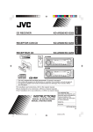
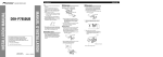
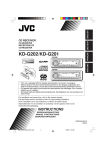
Typical Connections / !"#$ /
2
3
WOł–uLM« öOu²«
!"#$%&'()*+%,&
!"#$%&'
!" #$%!&'(" )*+,-.
!"
Before connecting: Check the wiring in the
vehicle carefully. Incorrect connection may
cause serious damage to this unit.
The leads of the power cord and those of the
connector from the car body may be different in
color.
1
°“√‡™◊ËÕ¡µËÕ·∫∫ª°µ‘ /
1
2
3
Connect the colored leads of the power cord
in the order specified in the illustration
below.
!"#$%&'()*+,-./+0
!"
!"#$%&'&()*+
°ËÕ•∑”°“•‡™•ËÕ¡µËÕ : µ•«®†Õ•°“•‡¥‘•†“¬‰ø„•••¬•µÏլ˓ߕ–¡—
¥•–«—լ˓„ÀȺ‘¥æ•“¥„•°“•‡™•ËÕ¡µËÕ™ÿ¥ª•–°Õ•™ÿ¥•’
°“•‡™•ËÕ¡µËÕº‘¥æ•“¥Õ“®∑”„Àȇ°‘¥§«“¡‡†’¬À“¬•È“¬·•ß°—•™ÿ¥ª•–
°Õ••’È ‰¥È“•µ–°—Ë«¢Õ߆“¬‰ø ·•–¢ÕßÕÿª°••ÏµËÕ‡™•ËÕ¡®“°µ—«•
ß••Õ“®¡’†’∑’Ë ‰¡Ë‡À¡•Õ•°—•
…—U?O?'?« w? „ö?Ýô« WJ³ý s1 b+Qð ∫q?O?u?²?UÐ ¡b³« q³,
Ê« s?J?1 Æ“U?N?'« qOuð WOKLŽ w QDš Àb×¹ ô v²Š W,bÐ
Æ“UN−K wIOIŠ qDŽ ‰uBŠ v« ¡vÞU)« qOu²« V³'¹
qu*« pKÝË WOzUÐdNJ« W,UD« pKÝ Êu nK²e¹ Ê« sJ1
Æ…—UO'« qJO¼ Êu sŽ
1 µËÕ “¬‰ø ’µ“¡≈”¥—∫∑’Ë√–∫ÿ„π√Ÿª¥È“π≈Ë“ß
2 ‡™◊ÕË ¡µËÕ°—∫ “¬Õ“°“»
3 ÿ¥∑È“¬ µËÕ Ë«π§«∫§ÿ¡°“√‡¥‘𠓬‰ø‡¢È“°—∫™ÿ¥ª√–°Õ∫™ÿ¥π’È
#$%&'
WOzUÐdNJ« W,UD« pK' W½uK*« „öÝô« qË«
ÆqHÝô« w œułu*« rÝd« w ·uu*« VOðd²UÐ
Æwz«uN« pKÝ qË«
Æ“UN'« l1 „öÝô« q1UŠ qË« ¨«dOš«
Connect the antenna cord.
Finally connect the wiring harness to the
unit.
15 A fuse
15 A Rear ground terminal
!"#$%
ø‘« Ï¢π“¥ 15 A
dO³1« ±µ “uO
®ÿ¥‡™◊ËÕ¡µËÕ “¬¥‘π¥È“πÀ≈—ß
1
15
wHK)« i¹—Q²« ·dÞ
Antenna terminal
!
¢—È« “¬Õ“°“»
wz«uN« ·dÞ
Black
3
2
œuÝ√
“¬ÕÕ° (Line out) (¥Ÿ·ºπ¿Ÿ¡
‰UF²ýô« ÕU²H1
*1
!"#$
*1
w½bF*« …—UO'« qJO¼ Ë« w½bF*« r''« v«
To a live terminal in the fuse block connecting to the car battery
(bypassing the ignition switch) (constant 12 V)
!"#$%&'()*+ !"#$,-./012
!"#$%&'()=12 V
Yellow*2
*2
’‡À≈◊Õß*2
dHò*
µËÕ°—∫¢—È«∑’Ë¡’°√–· ‰øøÈ“„π·ºßø‘« Ï ´÷ËßµËÕ°—∫·∫µ‡µÕ√’Ë√∂¬πµ
)
2 (‚¥¬‰¡ËµÈÕß„™È «‘∑™Ï®ÿ¥√–‡∫‘¥) (12 ‚«≈∑ϧß∑’Ë)
jD<« dE½«® j)« Ãdš
ÕU²H0 «—Ëd1® W¹—UD³« l1 Wuu*« “uOH« WŽuL−1 w w(« ·dD« v«
©Xu ±≤ XÐUŁ® ©‰UF²ýô«
Red
*2 Before checking the operation of this unit prior to
installation, this lead must be connected, otherwise power
cannot be turned on.
*2 !"#$%&'()*+,-.$/012345
!"#$%&
*2
«‘∑™Ï®ÿ¥√–‡∫‘¥
µËÕ°—∫‚§√ß‚≈À–À√◊Õ‡™ ´‘ ¢Õß√∂¬πµÏ
1
Line out (see diagram )
!"#$%& ©
To metallic body or chassis of the car
’¥”
Ignition switch
!
*1 Not included with this unit
*1 !"#$
*1 ‰¡Ë ‰¥È„ÀÈ¡“°—∫™ÿ¥ª√–°Õ∫π
“UN'« «c¼ l1 œÒËe1 dOž±*
’·¥ß
To an accessory terminal in the fuse block
dLŠ√
3
!"#$%&'()
·ºßø‘« “uOH« WŽuL−1 qš«œ wU{ô« ·dD« v«
“uOH« WŽuL−1
Blue with white stripe
!"#$
To the remote lead of other equipment or automatic antenna if any (200 mA max.)
!"#$%&'()*+,-.*/01&23 200 mA
’πÈ”‡ß‘π≈“¬¢“«
°ËÕπ°“√µ√«® Õ∫°“√∑”ß“π¢Õß™ÿ¥ª√–°Õ∫π’È°ËÕπ∑’Ë®–µ‘¥µ—Èß
µÈÕßµËÕ “¬µ–°—Ë«π’È°ËÕπ ¡‘©–π—Èπ®–‰¡Ë “¡“√∂‡ª‘¥‡§√◊ËÕ߉¥
Fuse block
!"
µËÕ°—∫¢—È« Ë«πª√–°Õ∫„π·ºßø‘« iOÐôUÐ jDe1 ‚—“« pKÝ
4 µËÕ “¬°—∫Õÿª°√≥ÏÕ◊ËπÀ√◊Õ‡ “Õ“°“»Õ—µ‚π¡—µ‘∂È“¡’ (¢π“¥ Ÿß ÿ¥ 200 mA)
V−¹ ¨VO+d²« q³, “UN'« «c¼ qOGAð h× q³, ∫≤*
W,UD« qOuð sJ1 ô p– ·öeÐ ¨pK'« «c¼ qOuð
ÆWOzUÐdNJ«
błË Ê« wJOðU1uðËô« wz«uN« Ë« dšô« “UN−K bFÐ sŽ rJײ« pKÝ v«
©dO³1« wKO1 ≤∞∞ bŠ vB,«®
5
White with black stripe
!"#$
White
Gray with black stripe
!"#$
Gray
’¢“«·∂∫¥”
œuÝôUÐ jDe1 iOЫ pKÝ
’¢“«
’‡∑“·∂∫¥”
iOÐ√
œuÝôUÐ jDe1 ÍœU1— pKÝ
Left speaker (front)
!"#$%
Green
Purple with black stripe
!"#$
’‡∑“
’‡¢’¬«·∂∫¥”
’‡¢’¬«
’¡Ë«ß·∂∫¥”
’¡«Ë ß
ÍœU1—
œuÝôUÐ jDe1 dCš« pKÝ
dCš«
œuÝôUÐ jDe1 w½«uł—« pKÝ
w½«uł—«
Right speaker (front)
!"#$%
Left speaker (rear)
!"#$%
3
Right speaker (rear)
!"#$%
≈”‚æß´È“¬ (ÀπÈ“)
≈”‚æߢ«“ (ÀπÈ“)
≈”‚æß´È“¬ (À≈—ß)
≈”‚æߢ«“ (À≈—ß)
©WO1U1ô«® Èd'O« WŽUL'«
©WO1U1ô«® vMLO« WŽUL'«
©WOHK)«® Èd'O« WŽUL'«
©WOHK)«® vMLO« WŽUL'«
3
Insta3-4_KD-G205(U)_f
Purple
Green with black stripe
!"#$
10/10/03, 1:44 PM
±
≤
≥
B
Connections Adding Other Equipment / Amplifier / !"#$%&'( /
°“√µËÕ‡æ‘Ë¡‡µ‘¡‡¢È“°—∫Õÿª°√≥ÏÕ◊Ëπ Ê / WOU{ô« Èdšô« …eNłô« qOuð
!" / ‡§√◊ËÕߢ¬“¬ / uB« reC1
You can connect an amplifier to upgrade your
car stereo system.
• Connect the remote lead (blue with white
stripe) to the remote lead of the other
equipment so that it can be controlled
through this unit.
• Disconnect the speakers from this unit,
connect them to the amplifier. Leave the
speaker leads of this unit unused.
!"#$% &'()*$+,-.
• !"#$%&'$()*+,-./0
!"#$%&'()'*+,-./
• !"#$%&'()*+,!-#$
!"#$%&'(
Remote lead
!"
≈”‚æßÀ≈—ß
R
R
“UNł ¡«œ« 5'ײ u reC1 qOuð pMJ1
Æ…—UO'« u¹dO²Ý
bFÐ sŽ rJײ« pKÝ qË« •
sŽ rJײ« pKÝ l1 ©iOÐôUÐ jD<« ‚—“ô«®
“UN'UÐ rJײ« r²¹ YO×Ð dšô« “UN−K bFÐ
Æ“UN'« «c¼ ‰öš s1
l1 rNKË« ¨“UN'« «c¼ s1 UŽUL'« qB« •
«c¼ UŽULÝ „öÝ« „dð« Æ uB« reC1
ƉULF²Ý« ÊËbÐ “UN'«
Y-connector (not supplied for this unit)
Y !"#$%&'()*
¢ÈÕµËÕ√Ÿªµ—« Y (‰¡Ë ‰¥È„ÀÈ¡“°—∫™ÿ¥ª√–°Õ∫π’)È
“¬µ–°—Ë«•–¬–‰°•
bFÐ sŽ rJײ« pKÝ
WOHK)« UŽUL'«
L
• ∂Õ¥≈”‚æßÕÕ°®“°™ÿ¥ª√–°Õ∫π’È ·≈È«µËÕ‡¢È“°—∫‡§√◊ËÕߢ¬“¬
∑‘Èß “¬µ–°—Ë«≈”‚æߢÕß™ÿ¥ª√–°Õ∫π’È ‰«È
Rear speakers
!"
INPUT
L
§ÿ≥ “¡“√∂µËÕ°—∫·Õ¡æ≈‘ø“¬‡ÕÕ√Ï ‰¥È ‡æ◊ÕË ‡æ‘¡Ë §ÿ≥¿“æ‡ ’¬ß„ÀÈ°∫— √–
∫∫ ‡µÕ√‘‚Õ¢Õß√∂¬πµÏ
• µËÕ “¬µ–°—«Ë √–¬–‰°≈ ( ’π”È ‡ß‘π≈“¬¢“«) ‡¢È“°—∫ “¬µ–°—«Ë √–¬–
‰°≈¢ÕßÕÿª°√≥ÏÕπË◊ Ê ‡æ◊ÕË ®– “¡“√∂§«∫§ÿ¡‚¥¬™ÿ¥ª√–°Õ∫π’ȉ¥È
©“UN'« l1 œÒËe1 dOž® Y qu1
Ò
JVC Amplifier
JVC !"
‡§√◊ËÕߢ¬“¬‡ ’¬ß JVC
JVC W+—U1 u reC1
*3
Remote lead (Blue with white stripe)
!"=E !"#$F
“¬µ–°—Ë«•–¬–‰°• ( ’πÈ”‡ß‘π≈“¬¢“«)
©iOÐôUÐ jD<« ‚—“ô«® bFÐ sŽ rJײ« pKÝ
LINE OUT
L
L
R
R
To the remote lead of other equipment or automatic antenna if any
KD-G205
!"#$%&'()*+,-.*/01&23
µËÕ “¬°—∫Õÿª°√≥ÏÕ◊ËπÀ√◊Õ‡ “Õ“°“»Õ—µ‚π¡—µ‘∂È“¡’
REAR FRONT
błË Ê« wJOðU1uðËô« wz«uN« Ë« dšô« “UN−K bFÐ sŽ rJײ« pKÝ v«
Front speakers
!"
Signal cord (not supplied for this unit)
!"#$ !"
≈”‚æßÀπÈ“
“¬‡§‡∫‘≈ —≠≠“≥ (‰¡Ë ‰¥È„ÀÈ¡“°—∫™ÿ¥ª√–°Õ∫π’È)
WO1U1ô« UŽUL'«
©“UN'« l1 œÒËe1 dOž® œdH1 pKÝ
*3 Firmly attach the ground wire to the
metallic body or to the chassis of the car—
to the place not coated with paint (if coated
with paint, remove the paint before
attaching the wire). Failure to do so may
cause damage to the unit.
PRECAUTIONS on power supply
and speaker connections:
• DO NOT connect the speaker leads of the
power cord to the car battery; otherwise,
the unit will be seriously damaged.
• BEFORE connecting the speaker leads of the
power cord to the speakers, check the
speaker wiring in your car.
+
L -
-
+
R -
-
+
+
*3 !"#$%&'($)*+,-./-.
!"#$%&'()*+,-$%./0
!"#$%&'()*+,-./"01
!"#
*3
!"#$%&'()*
µËÕ≈«¥ “¬¥‘π„ÀÈ·πËπ‡¢È“°—∫µ—«∂—߇À≈Á° À√◊Õµ—«∂—ß√∂ ˙
µ√ß Ë«π ∑’Ë ‰¡Ë¡’ ’‡§≈◊Õ∫ (À“°¡’ ’‡§≈◊Õ∫Õ¬ŸË „ÀÈ¢Ÿ¥ ’ÕÕ°°ËÕπ
°ËÕπµËÕ≈«¥ “¬¥‘π) À“°‰¡ËªØ‘∫—µ‘µ“¡§”·π–π”π’È
‡§√◊ËÕßÕ“®™”√ÿ¥À√◊Õ‡ ’¬À“¬‰¥
¢ÈÕ§«√√–«—ß ”À√—∫°“√µËÕ·À≈Ë߮˓¬°”≈—ß·≈–≈”‚æß:
• լ˓µËÕ “¬µ–°—Ë«‡§‡∫‘≈°”≈—ߢÕß≈”‚æ߇¢È“°—∫·∫µ‡µÕ√’Ë√∂¬πµÏ ¡‘©–π—
• !"#$%&'&()*+,-./0
!"#
• !"#$%&%' !"()*+, !"#$%&
Èπ™ÿ¥ª√–°Õ∫®–‰¥È√—∫§«“¡‡ ’¬À“¬¡“°
• °ËÕπ∑’®Ë –µËÕ “¬µ–°—«Ë ‡§‡∫‘≈°”≈—ߢÕß≈”‚æ߇¢È“°—∫≈”‚æß
„Àȵ√«® Õ∫°“√‡¥‘𠓬‰ø≈”‚æß„π√∂¢Õߧÿ≥„Àȇ√’¬∫√ÈÕ¬‡ ’¬°ËÕπ
+
L -
-
+
R -
-
+
+
4
Insta3-4_KD-G205(U)_4
4
6/10/03, 10:32 PM
Ë« qJO¼ l1 rJ×1 qJAÐ w{—ô« pK'« qË« ∫≥*
wKD*« dOž l{u*« l1 ‡‡ w½bF*« …—UO'« r'ł
‰“« ¨ÊU¼bUÐ wKD1 l{u*« ÊU+ «–«® ÊU¼bUÐ
qOuð WUŠ w Æ©pK'« qOuð q³, ÊU¼b«
Ê« sJ1 ÊU¼b« W«“« ÊËœ qJON« l1 pK'«
Æ“UN'« «cN —d{ p– V³'¹
WOzUÐdNJ« W,UD« b¹Ëeð ‰uŠ UNO³Mð
∫ UŽUL'« qOuðË
l1 UŽUL'« W,UÞ b¹Ëeð „öÝ« qÒuð ô •
‰uBŠ v« ÍœR¹ p– Êô ¨…—UO'« W¹—UDÐ
Æ UŽUL'K —d{
l1 UŽUL'« W,UÞ b¹Ëeð „öÝ« qOuð q³, •
qš«œ UŽUL'« „öÝ« WJ³ý h׫ ¨ UŽUL'«
Æpð—UOÝ
+
L -
-
+
R -
-
+
+