1
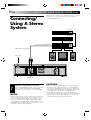
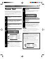
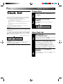
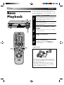
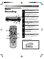
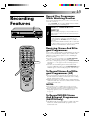
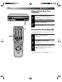
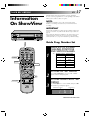
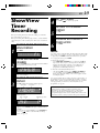
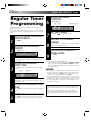
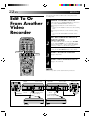
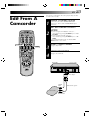
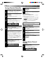
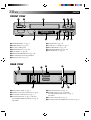
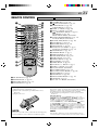
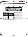
ENGLISH
VIDEO CASSETTE RECORDER
CONTENTS
SAFETY FIRST
HR-A637E/EH
Please find quick set up guide (3 pages) on the
rear at that instruction book.
2
Safety Precautions ................................... 2
INSTALLING YOUR NEW RECORDER
3
Basic Connections ...................................
Tune The TV To Your Video Recorder ......
Connecting/Using A Decoder
[A637EH only] ........................................
Connecting/Using A Satellite Tuner .........
Connecting/Using A Stereo System ..........
3
3
INITIAL SETTINGS
7
4
5
6
Tuner Set ................................................. 7
Clock Set ................................................. 8
PLAYBACK
10
Basic Playback ...................................... 10
Playback Features .................................. 11
RECORDING
14
Basic Recording .................................... 14
Recording Features ................................ 15
CH SET
A
B
OPERATE
STORE
CLOCK DISPLAY
2
1
2
3
ADD TIME
4
6
5
DAILY
7
8
C.RESET
AUX
CANCEL
0
START
STOP
WEEKLY
9
TIMER
TV
PROG.
DATE
EXPRESS PROGRAMMING
AUDIO MONITOR
TV/VIDEO
TV
VCR
(MONITOR)
PROG C
HECK
1
G
PRO TV VOL.
3
OK
OPERATE
TIMER
TV PROG
D
M
D W
NORM
L R
VIDEO
SP/LP
q
17
Information On ShowView ....................
Guide Prog. Number Set .....................
ShowView Timer Recording ..................
Regular Timer Programming ..................
Check And Cancel Programmes ..........
PDC/VPS Recording ...........................
17
17
19
20
21
21
EDITING
22
Edit To Or From Another Video
Recorder ............................................... 22
Edit From A Camcorder ......................... 23
PUSH JOG
SP
LP
I T R EP
TIMER RECORDING
6
Unless otherwise indicated, the recorder
illustrations appearing in this instruction
manual are of the HR-A637EH.
PAL
INSTRUCTIONS
USING THE CONFIRMATION DISPLAY
24
Storing Channels Manually ...................
Delete A Channel ..................................
Change Station Channel Position ..........
Set Stations ............................................
Fine-Tuning Channels Already Stored ....
24
24
24
25
25
TV STATION AND ID LIST
26
TROUBLESHOOTING
27
QUESTIONS AND ANSWERS
29
INDEX
30
SPECIFICATIONS
33
PU30425-1859
EN
2 EN
SAFETY FIRST
Safety Precautions
The rating plate and the safety caution are on the rear of the unit.
WARNING: DANGEROUS VOLTAGE INSIDE
WARNING: TO PREVENT FIRE OR SHOCK HAZARD, DO NOT EXPOSE THIS UNIT TO RAIN OR
MOISTURE.
CAUTION
n When you are not using the recorder for a long period of
time, it is recommended that you disconnect the power
cord from the mains outlet.
n Dangerous voltage inside. Refer internal servicing to
qualified service personnel. To prevent electric shock or
fire hazard, remove the power cord from the mains
outlet prior to connecting or disconnecting any signal
lead or aerial.
WARNING
There are two different types of SECAM colour systems:
SECAM-L, used in FRANCE (also called SECAM-West), and
SECAM-B, used in Eastern European countries (also called
SECAM-East).
1.This recorder can also receive SECAM-B colour
television signals for recording and playback.
2.Recordings made of SECAM-B television signals produce
monochrome pictures if played back on a video recorder
of SECAM-L standard, or do not produce normal colour
pictures if played back on a PAL video recorder with
SECAM-B system incorporated (even if the TV set is
SECAM-compatible).
3.SECAM-L prerecorded cassettes or recordings made with
a SECAM-L video recorder produce monochrome
pictures when played back with this recorder.
4.This recorder cannot be used for the SECAM-L standard.
Use a SECAM-L recorder to record SECAM-L signals.
For Italy:
“It is declared that this product, brand JVC, conforms to the
Ministry Decree n. 548 of 28 Aug.’95 published in the
Official Gazette of the Italian Republic n. 301 of 28 Dec.’95”
PAL
n Only cassettes marked “VHS” can be used with this
videorecorder.
n HQ VHS is compatible with existing VHS equipment.
n ShowView is a trademark applied for by Gemstar Development Corporation. The ShowView system is manufactured
under licence from Gemstar Development Corporation.
IMPORTANT
n Please read the various precautions on this page before
installing or operating the recorder.
n It should be noted that it may be unlawful to re-record
pre-recorded tapes, records, or discs without the consent
of the owner of copyright in the sound or video recording, broadcast or cable programme and in any literary,
dramatic, musical, or artistic work embodied therein.
The OPERATE button does not completely shut off mains
power from the unit, but switches operating current on and
off.
Video tapes recorded with this video recorder in the LP
(Long Play) mode cannot be played back on a single-speed
video recorder.
Failure to heed the following precautions may result in
damage to the recorder, remote control or video
cassette.
1. DO NOT place the recorder . . .
... in an environment prone to extreme temperatures or
humidity.
... in direct sunlight.
... in a dusty environment.
... in an environment where strong magnetic fields are
generated.
... on a surface that is unstable or subject to vibration.
2. DO NOT block the recorder’s ventilation openings.
3. DO NOT place heavy objects on the recorder or remote
control.
4. DO NOT place anything which might spill on top of the
recorder or remote control.
5. AVOID violent shocks to the recorder during transport.
MOISTURE CONDENSATION
Moisture in the air will condense on the recorder when you
move it from a cold place to a warm place, or under extremely
humid conditions—just as water droplets form in the surface of
a glass filled with cold liquid. Moisture condensation on the
head drum will cause damage to the tape. In conditions where
condensation may occur, keep the recorder turned on for a few
hours to let the moisture dry.
ABOUT HEAD CLEANING
Accumulation of dirt and other particles on the video heads
may cause the playback picture to become blurred or interrupted. Be sure to contact your nearest JVC dealer if such
troubles occur.
INSTALLING YOUR NEW RECORDER
Basic
Connections
21-pin SCART
connector
Aerial
terminal
TV Aerial
Cable
1
3
RF Cable
(provided)
21-pin SCART Cable
RF output
channel
adjustment
screw
Mains
Power Cord
Mains outlet
**
Rear View
RF TEST switch
3
It’s essential that your video recorder be properly connected.
Follow these steps carefully. THESE STEPS MUST BE
COMPLETED BEFORE ANY VIDEO OPERATION CAN BE
PERFORMED.
2
Back of TV
EN
AV1 IN/OUT
4
CHECK CONTENTS
Make sure the package contains all of the accessories
listed in “Specifications” (Z pg. 33).
SITUATE RECORDER
Place the recorder on a stable, horizontal surface.
CONNECT RECORDER TO
TV
The connection method you use depends on the type
of TV you have.
RF CONNECTION
● To Connect To A TV With NO AV Input Terminals . . .
a– Disconnect the TV aerial cable from the TV.
b– Connect the TV aerial cable to the ANT. IN jack
on the rear panel of the recorder.
c– Connect the provided RF cable between the RF
OUT jack on the rear panel of the recorder and
the TV’s aerial terminal.
Before operating the recorder, make sure the TV’s
channel is set to the VIDEO channel.
AV CONNECTION
● To Connect To A TV With AV Input Terminals . . .
a– Connect the aerial, recorder and TV as per “RF
CONNECTION”.
b– Connect an optional SCART cable between the
AV1 IN/OUT socket on the rear panel of the
recorder and the TV’s 21-pin SCART connector.
c– Set the RF TEST switch to OFF.
Before operating the recorder, make sure the TV is set
to the VIDEO (or AV) mode.
CONNECT RECORDER TO
MAINS
Plug the end of the mains power cord into a mains
outlet.
The video recorder sends picture and sound signals via the RF
connecting cable to your TV on UHF channel 36.
Tune The TV
To Your Video 1
Recorder
2
TURN ON THE RECORDER
Press OPERATE.
SELECT OUTPUT MODE
Set the RF TEST switch on the back of the recorder to
ON.
CONTINUED ON NEXT PAGE.
4 EN
INSTALLING YOUR NEW RECORDER (cont.)
3
4
SET TV CHANNEL
Set your TV to the video channel (UHF channel 36).
Two white bars appear on screen vertically.
● Tune the TV until the bars are as clear as they can be.
● Your TV should be set to the channel designated for
use with a video recorder, or to a spare channel if
there is not a specified video channel on your TV.
RESET OUTPUT MODE
Return the RF TEST switch to OFF.
NOTES:
● If CH36 is occupied by a local station, adjust the RF output
channel adjustment screw to use another channel between
CH32 and CH40 instead.
● If some interference noise is continually seen on the screen,
consult your JVC dealer.
Connecting/
Using A
Decoder
(A637EH only)
TV Receiver
RF Cable
(provided)
TV Aerial
Cable
AV2 IN/DECODER
AV2 SELECT switch
Rear View
AV1 IN/OUT
Decoder
The AV2 IN/DECODER connector can be used as an input
terminal for an external decoder (descrambler). Simply connect
a decoder and you can enjoy the variety of programming that is
available through scrambled channels.
1
2
3
SELECT INPUT MODE
Set the AV2 SELECT switch to “DECODER”.
CONNECT DECODER
Connect your recorder’s AV2 IN/DECODER connector
to the decoder’s Euroconnector using a 21-pin SCART
cable.
SET TUNER
Follow the procedure starting on page 7.
EN
5
The AV2 IN (/DECODER) or AV1 IN/OUT connector can be
used as an input terminal for a satellite tuner. Simply connect a
satellite tuner and you can enjoy the wide variety of satellite
programming.
Connecting/
Using A
Satellite Tuner 1
2
TV Receiver
RF Cable
(provided)
TV Aerial
Cable
3
AV2 IN (/DECODER)
CONNECT SATELLITE
TUNER
Connect an optional 21-pin SCART cable between the
satellite tuner’s Euroconnector and your recorder’s AV2
IN (/DECODER) connector.
SELECT INPUT MODE
(A637EH only)
Set the AV2 SELECT switch to “AV2”.
PREPARE TO WATCH A
SATELLITE PROGRAMME
Select the appropriate channel on the satellite tuner.
Then set the auxiliary mode by pressing NUMBER key
“0” or TV PROG. on the remote control until “AU2”
appears on the recorder’s front display panel.
NOTE:
AV2 SELECT switch
AV1 IN/OUT
Rear View
Satellite antenna
Satellite tuner
Decoder
When connecting a satellite tuner together with a decoder . . .
. . . first connect the decoder to the decoder input of the
satellite tuner, then connect the satellite tuner’s output to
the recorder’s AV2 IN (/DECODER) connector.
Refer to the instruction book for the satellite tuner and
decoder.
6 EN
INSTALLING YOUR NEW RECORDER (cont.)
Connecting/
Using A Stereo
System
These instructions enable you to connect your video recorder to
your Hi-Fi stereo system (if you have one) and listen to the
soundtrack through the stereo.
FM Tuner
CD Player
Stereo Amplifier
AUX IN or TAPE MONITOR
I
I I I I I I I I
I
I I
I
I
I I I I I I I I
I
I I
I
I I I I I I I I
I
I I
I
I
I
I
I
I
Audio Cable (not provided)
Mains outlet
Speaker
L
R
AUDIO OUT
AV2 IN/DECODER
AV2 SELECT
/ RF TEST
ANT. IN
32
ON
AV2
AV1 IN/OUT
RF OUT
Rear View
AUDIO OUT
1
MAKE CONNECTIONS
Connect the AUDIO OUT L and R connectors on your
video recorder to the AUX IN or TAPE MONITOR
terminals on your stereo system’s receiver or amplifier.
NOTES:
Speaker
40
DECODER
OFF
Television
● When connecting your recorder’s audio output connectors to
a stereo amplifier, make sure you connect L and R correctly.
● If stereo or bilingual TV broadcasts are receivable in your
area, this recorder can record them independently of the TV
set and play them back through the connected stereo system.
● When listening to sound through the connected stereo system,
turn the TV’s volume down completely.
CAUTIONS:
● This recorder has a dynamic range of more than 80 dB with
regards to its Hi-Fi audio capability. It is recommended that
you check the maximum level if you are going to listen to the
Hi-Fi audio signals through a stereo amplifier. A sudden surge
in the input level to the speakers may damage them.
● Some speakers and televisions are specially shielded to
prevent television interference. If both are of the non-shielded
type, do not place the speakers adjacent to the TV set as this
can adversely affect the video playback picture.
INITIAL SETTINGS
EN
Tuner Set
Your recorder needs to memorise all necessary stations in
channel positions in order to record TV programmes. The Auto
Tuning System automatically assigns all receivable stations in
your area to call them up with the TV PROG. buttons without
going through any vacant channels.
6
The following procedure describes how to select automatic
channel setting.
1
2
3
4
TURN ON THE RECORDER
ACCESS CONFIRMATION
DISPLAY
The channel position, channel and station name (ID –
Z pg. 26) of the stations located by your recorder
appear in a Confirmation display.
(EX.)
Channel Position Channel Station Name
≠
≠
≠
Press OPERATE.
Ch=Regular CC=Cable
Confirm all the stored stations by using PUSH JOG%fi.
ACCESS CH. SET DISPLAY
RETURN TO NORMAL
DISPLAY
Press and hold CH SET for more than 2 seconds.
“AUTO” appears on the front display panel.
ACCESS COUNTRY DISPLAY
Press OK and the Country display appears on the front
display panel.
SELECT COUNTRY
Press PUSH JOG %fi to select your country’s name.
The available country names appear in the following
order:
“AUT” (Österreich)
“BELG” (Belgium)
“DEUT” (Deutschland)
“DK” (Danmark)
“ESP” (España)
“GRCE” (Greece)
“ITA” (Italia)
“OTHR” (Others)
“SWED” (Sverige)
“SUOM” (Suomi)
“SUIS” (Suisse)
“PORT” (Portugal)
“NOR” (Norsk)
“NL” (Nederland)
● If you selected “BELG” or “SUIS” above . . .
. . . refer to “INFORMATION” at the end of this page.
5
7
START AUTO CHANNEL
SET
Press OK and “AUTO” blinks on the front display
panel.
● If you selected “BELG” or “SUIS” in step 4 . . .
. . . refer to “INFORMATION” at the end of this page.
7
Press CH SET.
● Using the Confirmation display, you can skip or add
channel positions, enter station names and perform
other operations. Refer to page 24 for the procedures.
● Depending on the reception conditions, the stations
may not be stored in order, and the station names
may not be stored correctly.
● If you own the A637EH and use a decoder, Z pg. 24
for information on scrambled broadcasts.
NOTES:
● Fine tuning is performed automatically when you select
“AUTO” in step 2. If you want to perform it manually, refer to
page 25.
● To set the tuner manually, refer to “Storing Channels
Manually” (Z pg. 24).
INFORMATION
If you selected “BELG” or “SUIS” in step 4, you need to
enter the language used in your area. This ensures that
stations broadcasting programmes in your language will be
stored in the highest channel positions. Once you select a
language, the recorder selects the region.
After pressing OK in step 5, perform the following
procedure:
1. Press PUSH JOG%fi to select your language.
● Users living in Belgium should select “DEUT”, “FRA”
or “NL”.
● Users living in Suisse should select “DEUT”, “FRA” or
“ITAL”.
The available languages appear in the following order:
“ENG” (English)
“DEUT” (Deutsch)
“FRA” (Français)
“ITAL” (Italiano)
“CAST” (Castellano)
2. Press OK, then go to step 6.
“DK” (Dansk)
“SUOM” (Suomi)
“NOR” (Norsk)
“SWED” (Svenska)
“NL” (Nederlands)
8 EN
INITIAL SETTINGS (cont.)
Clock Set
If you performed Auto Channel Set (Z pg. 7), the recorder’s
built-in clock is also set automatically. The Auto and Manual
clock setting procedures are necessary when . . .
– a power outage of more than 3 minutes occurs.
– the tuner has been set manually.
– the user desires to set the clock slightly ahead of the actual
time.
– the clock was not set even after Auto Tuner Set was
performed.
Whether you perform Auto or Manual clock setting, you can
use the convenient Just Clock function.
Just Clock
The Just Clock function provides accurate time keeping through
automatic adjustments at regular intervals, by reading data from
a PDC signal.
The Just Clock option appears in the Just Clock display, and can
be set “ON” or “OFF” (the default setting is “ON”). Press OK
until the Just Clock setting begins blinking, then press PUSH
JOG%fi to change the setting.
Just Clock Channel Position
≠
Preparation
1
2
TURN THE RECORDER ON
Press OPERATE.
ACCESS CLOCK SET
DISPLAY
Press CLOCK on the remote control. The Clock Set
display appears.
Auto Clock Set
IMPORTANT: If you turn off Just Clock off, the accuracy of your
recorder’s built-in clock may be reduced, which could
adversely effect timer recording.
Both Auto and Manual clock setting procedures begin from step
3.
4
At the Clock Set display, press PUSH JOG . The Clock
Set display blinks and clock setting begins.
%
3
SET CLOCK
AUTOMATICALLY
● If the Just Clock channel position isn’t set to the
channel position on which Auto Clock data is
received, “Err”(or) appears, and then the display from
step 2 reappears. To set the Just Clock channel
position, press OK until the Just Clock channel
position begins blinking, then cycle through the
numbers by pressing PUSH JOG%fi until the number
representing the channel position in which the station
transmitting clock setting data is stored appears.
RETURN TO NORMAL
DISPLAY
Once clock setting is completed, press CLOCK to return
to the normal display.
EN
Manual Clock Set
3
SET DATE AND TIME
Press PUSH JOG%fi to set the hour, then press OK. The
“minutes” display begins blinking. Repeat the procedure to set the minutes, day, month and year.
Hour
≠
Minutes
≠
Day Month
≠
≠
D
Year
≠
M
After inputting the year, press OK and the Just Clock
display appears.
4
SET JUST CLOCK
The default setting is “ON”. Set as desired by pressing
PUSH JOG%fi, then press OK.
● If you set to “OFF”, you can disregard the next step as
you won’t be able to receive regular clock adjustments.
5
6
SET CLOCK DATA SOURCE
CHANNEL POSITION
The recorder is preset to receive clock setting and
adjustment data from channel position 1. Press PUSH
JOG%fi to set the channel position to the number
representing the station transmitting clock setting data,
then press OK.
START CLOCK OPERATION
Press CLOCK.
NOTES:
9
● Auto Clock and Just Clock require a PDC signal, and will not
operate with a VPS signal.
● Just Clock (when set to “ON”) enables adjustment of the
recorder’s built-in clock every hour on the hour, except for 11
o’clock in the evening and midnight.
● Just Clock is not effective when . . .
– the recorder’s power is on (unless the recorder is tuned to
the same channel position selected in the Just Clock
display).
– the recorder is in the Timer mode.
– a difference of more than 3 minutes exists between the
built-in clock’s time and the actual time.
● If Just Clock is set to “ON”, the recorder’s clock is automatically adjusted at the start/end of Summer Time.
● Auto clock setting and Just Clock may not function properly
depending on the reception condition.
● During Manual clock setting, if the day and month data are
invalid (such as 31st April), the month digits are cleared
automatically and the day digits begin blinking. Input the
correct data.
● If, in step 3 of the Manual Clock Set procedure, the year digits
are automatically cleared and the day digits begin blinking, it
is possible that you have input 29th February for a non-leap
year. Input the correct data.
10 EN
PLAYBACK
The easiest, most basic operation possible with your video
recorder is tape playback. Already-recorded signals on a video
tape are read by your video recorder and displayed on your TV
just like a TV programme.
RE
FF
PLAY
Basic
Playback
1
W
STOP/EJECT
6
3
4
5
6
7
8
9
2
4
0
FIND PROGRAMME START
POINT
If the tape is advanced past the start point, press REW.
To go forward, press FF.
.
3
2
2
Make sure the window side is up, the rear label side is
facing you and the arrow on the front of the cassette is
point toward the recorder. Don’t apply too much
pressure when inserting.
● The recorder power comes on automatically and the
counter is reset to 0:00:00.
● If the record safety tab has been removed, playback
begins automatically.
q
1
LOAD A CASSETTE
START PLAYBACK
Press PLAY.
STOP PLAYBACK
Press STOP on the remote or STOP/EJECT on the
recorder’s front panel. Then press STOP/EJECT to
remove the cassette.
AY
PL
FF
Usable cassettes
3
ST
O
P
REW
1
● Compact VHS camcorder recordings can be played on
this video recorder. Simply place the recorded cassette
into a VHS Cassette Adapter and it can be used just like
any full-sized VHS cassette.
● This video recorder can record on regular VHS and
Super VHS cassettes. However, it will record and play
back regular VHS signals only. It is not possible to play
back a recorded Super VHS tape.
EN
High-Speed Search
Playback
Features
Take advantage of special functions possible with the recorder’s
controls or the remote control.
Still Picture/Frame-By-Frame
Playback
Press PAUSE. If there is vertical jitter, use the TV PROG.
buttons to correct the picture.
ACTIVATE FRAME-BY-FRAME
PLAYBACK
Press PAUSE again.
1
● For short searches, during playback or still, press and
hold FF or REW for over 2 seconds. When released,
normal playback resumes.
NOTE:
When playing back LP recordings in the search, still, or frame
by frame playback mode, the picture will be distorted, and
there may be a loss of colour.
Manual Tracking
Your video recorder is equipped with automatic tracking
control. During playback, you can override this and adjust the
tracking manually by pressing the TV PROG. buttons.
OR
Press PUSH JOG
or
.
Slow Motion
ACTIVATE SLOW-MOTION
PLAYBACK
During still picture, press and hold PAUSE for 2
seconds, then release. Press and release again to return
to still picture.
OR
%
%
During still picture, press and hold PUSH JOG
Release to return to still picture.
or
.
1
2
To resume normal playback, press PLAY.
Variable-Speed Search
During playback, press PUSH JOG
%
ACTIVATE VARIABLE-SPEED
SEARCH
or
%
1
During playback or still, press FF for forward highspeed search, or REW for reverse high-speed search.
To resume normal playback, press PLAY.
To resume normal playback, press PLAY.
1
ACTIVATE HIGH-SPEED
SEARCH
%
2
PAUSE DURING PLAYBACK
%
1
11
.
● The more times you press, the faster the playback
picture moves.
● To decrease speed, press the button for the opposite
direction.
To resume normal playback, press PLAY.
3
OVERRIDE AUTOMATIC
TRACKING
Press
on the remote to engage manual tracking.
ADJUST TRACKING
MANUALLY
Press TV PROG. + or – to adjust tracking.
RETURN TO AUTOMATIC
TRACKING
Press
on the remote to re-engage automatic
tracking.
NOTE:
When a new tape is inserted, the recorder enters the automatic
tracking mode automatically.
12 EN
PLAYBACK (cont.)
Instant ReView
NTSC Playback
Simply by pressing a single button, the recorder power comes
on, rewinds, and begins playback of the last timer-recorded
programme. If you have several programmes recorded, you can
easily access any of them.
Your video recorder is equipped with NTSC circuitry that can
play back NTSC tapes.
NOTE:
1
2
Before starting, make sure that the recorder is off and that the
Timer mode is disengaged.
1
ACTIVATE INSTANT
REVIEW
Press REVIEW. The recorder power comes on and the
recorder searches for the index code indicating the start
of the last timer-recorded programme. Once it’s found,
playback begins automatically.
The front display panel tells you how many
programmes have been recorded. If you have, for
example, 3 programmes, “REV 3” appears and blinks.
To watch the first of the 3 programmes, press REVIEW
three times. The recorder searches and begins playback
automatically. You can access a programme as far as 9
index codes away from the current tape position.
NOTE:
Instant ReView is not possible while the recorder is in the Timer
mode.
Repeat Playback
Your video recorder can automatically play back the whole tape
20 times repeatedly.
LOAD A CASSETTE
Insert a cassette recorded in NTSC.
START PLAYBACK
Press PLAY. “NT” appears on the display panel.
● Some TVs shrink the picture vertically and place
black bars at the top and bottom of the screen. This is
not a malfunction on the part of either the video
recorder or the TV.
● The picture may roll up and down. This can be
corrected using the V-HOLD control found on some
TVs. (This cannot be corrected if the TV does not
have a V-HOLD control.)
● The counter and elapsed tape time readings will be
incorrect.
● During search, still, or frame-by-frame playback, the
picture will be distorted, and there may be a loss of
colour.
● Depending on the type of TV, the top and bottom
portions of superimposed displays may be cut off
during NTSC playback.
Soundtrack Selection
Your video recorder is capable of recording three
soundtracks (HI-FI L, HI-FI R and NORM) and will play
back the one you select.
During Playback
1
2
3
START PLAYBACK
Press PLAY.
Pressing AUDIO MONITOR on the remote control
changes the soundtrack being played back as follows:
TRACK
Recorder’s Front Panel
ACTIVATE REPEAT
PLAYBACK
Press PLAY and hold for over 5 seconds, then release.
● The Play indicator ( ) on the display panel blinks
slowly.
● The tape plays 20 times automatically, and then
stops.
STOP PLAYBACK
Press STOP at any time to stop playback.
NOTE:
Pressing PLAY, REW , FF or PAUSE also stops Repeat Playback.
L+R
USE
For Hi-Fi stereo tapes
L
For main audio of Bilingual tapes
R
For sub audio of Bilingual tapes
NORM
For audio-dubbed tapes
L + R + NORM
For audio-dubbed tapes
NOTES:
● “L + R” should normally be selected. In this mode, Hi-Fi
stereo tapes are played back in stereo, and the NORM
track is played back automatically for tapes with only
normal audio.
● For instructions on recording stereo and bilingual
programmes, refer to page 15.
EN
13
Index Search
Remote A/B Code Switching
Your recorder automatically marks index codes at the beginning
of each recording. This function gives you quick access to any
one of 9 index codes in either direction.
The remote control is capable of controlling two JVC video
recorders independently; one set to respond to the remote
control’s A code control signals and another set to respond to B
code control signals. The remote control is preset to send A
code signals because your video recorder is initially set to
respond to A code signals. You can easily modify your video
recorder to respond to B code signals.
NOTE:
Before starting, make sure the recorder is in the Stop mode.
%
%
Press PUSH JOG or (™ or £). “– 1” or “+ 1”
is displayed on the display panel and search begins in
the corresponding direction.
%
● To access index codes 2 through 9, press PUSH JOG
or repeatedly until the correct index number is
displayed.
%
1
ACTIVATE INDEX SEARCH
%
Ex.: To locate the beginning of B from the current
position, press PUSH JOG twice.
To locate the beginning of D from the current
position, press PUSH JOG once.
%
Current position
A
C
–1
D
1
E
2
F
3
%
%
–2
B
1
2
3
Index number
● When the specified index code is located, playback
begins automatically.
4
REMOVE POWER SUPPLY
Unplug the mains power cord from the mains outlet.
SET A/B CODE SWITCH
Set to B.
RE-SUPPLY POWER
Plug the mains power cord back into the mains outlet.
TURN THE RECORDER ON
Press OPERATE on the remote control. The recorder
will now only respond to B code signals.
NOTE:
Some TV sets may malfunction in response to the B mode. If
this happens, switch back to the A mode.
Next Function Memory
You can set your recorder’s power to go off automatically after
the tape is fully rewound. Before starting, make sure the
recorder is in the Stop mode.
For Automatic Power Off After Tape Rewind . . .
. . . press REW, then press OPERATE within 2 seconds.
Information On Colour
System
You can also record SECAM signals, or play back a MESECAM
tape on this recorder. When a MESECAM tape is played back,
“MES” appears on the display panel. MESECAM is the designation for tapes with SECAM signals that have been recorded on a
MESECAM-compatible PAL video recorder.
14 EN
RECORDING
TV signals being received by the recorder’s built-in tuner can be
recorded onto a video tape. You can “capture” a TV programme
using your video recorder.
Basic
Recording
PA
US
E
TV PROG.
PLAY
1
6
STOP/EJECT
RD
RE
CO
SP
/L
P
q
2
2
3
4
5
6
7
8
9
TV/VIDEO
NUMBER
1
0
TV PROG.
SP/LP
PLAY
PAUSE
RECORD
STOP
3
1
2
3
4
5
6
LOAD A CASSETTE
Insert a cassette with the record safety tab intact.
● The counter is reset to 0:00:00 and the recorder
power comes on automatically.
● If your recorder is connected to the TV via AV connection, press TV/VIDEO to select the VIDEO mode.
[A637EH only]
CHOOSE A PROGRAMME
Press TV PROG. +/– or the NUMBER keys to select the
channel you wish to record. The name of the station
appears in the recorder’s display panel for 5 seconds,
followed by the channel position number. (Only
stations that appear in the Confirmation display will be
displayed.)
SET TAPE SPEED
Press SP/LP (
). Check the SP/LP indicator on the
recorder display panel to confirm the selected tape
speed.
START RECORDING
Press and hold RECORD and PLAY on the remote
control, or press RECORD on the recorder.
PAUSE/RESUME
RECORDING
Press PAUSE. Press PLAY to resume recording.
STOP RECORDING
Press STOP on the remote control or STOP/EJECT on
the recorder. Then press STOP/EJECT to remove the
cassette.
Accidental erasure prevention
● To prevent accidental recording on a recorded cassette,
remove its safety tab. To record on it later, cover the hole
with adhesive tape.
Record safety tab
EN
Record One Programme
While Watching Another
Recording
Features
TV PROG.
If you own the A637EH and your recorder is connected to the
TV via AV connection, . . .
. . . press TV/VIDEO. The recorder’s VIDEO indicator and the
TV broadcast being recorded disappear.
q
6
1
SELECT CHANNEL TO
WATCH
Once recording is in progress, all you need to do is to
set the channel controls on the TV for the station you
wish to view.
● The programme selected with the TV’s channel
controls appears on the TV screen while the one
selected with the TV PROG. button is recorded on
the tape.
● If you own the A637EH and a decoder is connected
to the recorder (Z pg. 4) you can select a scrambled
channel as well with the TV channel controls.
Receiving Stereo And Bilingual Programmes
2
1
2
3
4
5
6
7
8
9
Your recorder is equipped with a Sound-Multiplex decoder (A2)
and, if you own the A637EH, a Digital stereo sound decoder
(NICAM) as well, making reception of stereo and bilingual
broadcasts possible.
0
TV PROG.
● To listen to a stereo programme, press AUDIO MONITOR
until “L” and “R” appear on the front display panel.
● To listen to a bilingual programme, press AUDIO MONITOR
until either “L” or “R” appears on the front display panel (as
required).
● To listen to the Standard (regular monaural) audio while
receiving a NICAM broadcast, press AUDIO MONITOR until
“NORM” appears on the front display panel. (A637EH only)
D
IO
M
O
N
EO
IT
ID
O
R
/V
TV
AU
15
3
1
To Record Stereo And Bilingual Programmes (A2)
● Stereo programmes are automatically recorded in stereo on
the Hi-Fi audio track (with the normal audio track recording
mixed L and R channel sound).
● Bilingual programmes are automatically recorded in bilingual
on the Hi-Fi audio track. The main soundtrack will be recorded
on the normal audio track.
NOTES:
● If the quality of stereo sound being received is poor, the
broadcast will be received in monaural with better quality.
● Before playing back a programme recorded in stereo, or a
bilingual programme, refer to “Soundtrack Selection”
( Z pg. 12)
To Record NICAM Stereo
And Bilingual Programmes
(A637EH only)
● The NICAM audio programme will be recorded on the Hi-Fi
audio track, and the Standard audio programme on the
normal audio track.
16 EN
RECORDING (cont.)
Elapsed Recording Time
Indication
You can check the exact time of a recording.
RECORD
q
DISPLAY
2
1
2
3
4
5
6
7
8
9
6
1
2
● If you press DISPLAY again, clock display appears.
RESET COUNTER
Press C. RESET before starting recording or playback.
● The counter is reset to “0:00:00” and shows the exact
elapsed time as the tape runs.
This easy method lets you record for from 30 minutes to 6 hours
(selectable in 30-min. increments), and shuts the recorder off
after recording is finished.
EO
ID
/V
TV
3
1
Press DISPLAY so that a counter reading appears on the
dispay panel.
Instant Timer Recording (ITR)
0
C.RESET
SET COUNTER DISPLAY
1
2
3
START RECORDING
Press RECORD on the recorder.
ENGAGE ITR MODE
Press RECORD again. ITR blinks and 0:30 appears on
the front display panel.
SET RECORDING DURATION
If you want to record for more than 30 minutes, press
RECORD to extend the time. Each press extends
recording time by 30 minutes.
NOTE:
You can only perform ITR using the RECORD button on the
recorder’s front panel.
TIMER RECORDING
EN
Information
On ShowView
17
With ShowView, timer programming is greatly simplified
because each TV programme has a corresponding code number
which your recorder is able to recognise.
NOTE:
“Guide Prog. Number” refers to the assigned TV station
numbers, according to broadcast area, for ShowView timer
recording.
IMPORTANT
q
CH SET
Guide Prog. Number Set
1
2
1
NUMBER
6
Perform the following procedure after the channel setting steps
on pages 7 and 24 – 25, and after the Clock Set procedure on
page 8.
After setting the Guide Prog. Numbers, the station names and
channel positions may be incorrect if you stored or skipped
channels. In this case, re-perform Guide Prog. Number setting.
2
3
4
5
6
7
8
9
MAKE LIST OF STORED
CHANNEL POSITIONS
AND STATION NAMES
(Ex.) Channel position
Station name
1
ARD
2
ZDF
3
WDR
0
CANCEL
TV PROG.
3
1
OK
2
PUSH JOG
3
ACCESS CH. SET DISPLAY
Press and hold CH SET for over 2 seconds. “AUTO”
appears on the front display panel.
ACCESS GUIDE PROG. SET
DISPLAY
Press PUSH JOG%fi to select “GUID”, then press OK.
The Guide Prog. Set display appears.
Channel Position
≠
Guide Prog.
≠
CONTINUED ON NEXT PAGE.
18 EN
%
Press OK, and “– –” appears. Then, using the NUMBER
keys, input the ShowView number (found in most TV
listings) of a program scheduled to be broadcast on
each station on the list from step 1, starting at the top. If
you enter the wrong number, press CANCEL and input
the correct number.
If you already know the Guide Prog. number for a station . . .
1– After step 3, press PUSH JOG .
● The Guide Prog. number begins blinking.
2– Enter the Guide Prog. number using the NUMBER keys or
PUSH JOG%fi, then press PUSH JOG .
● The Channel Position number begins blinking.
3– Enter the channel position using the NUMBER keys or
PUSH JOG%fi, then press OK.
● Repeat 1 and 3 as necessary.
4– Press CH SET.
%
4
ENTER SHOWVIEW
NUMBER
TIMER RECORDING (cont.)
Satellite Tuner Users
5
4
ENTER CHANNEL POSITION
NUMBER
Press OK and Channel Position number begins
blinking.
Channel Position Guide Prog.
≠
≠
If the blinking Channel Position number agrees with the
channel position . . .
. . . press OK.
If the numbers do not agree . . .
. . . input the channel position using PUSH JOG% fi or
the NUMBER keys, then press OK.
● If you input the ShowView number of a program that
has already aired, “Err”(or) appears on the front
display for a few seconds. Input the correct
ShowView number.
● Repeat steps 4 and 5 as necessary.
6
RETURN TO NORMAL
DISPLAY
Press CH SET and selection is complete.
To set the Guide Prog. numbers for satellite broadcasts, be
sure to select “AU2” in step 5 by using the NUMBER key
“0” or TV PROG. +/–.
EN
ShowView
Timer
Recording
Before performing ShowView Timer Recording, see “Information on ShowView” on page 17.
Before performing the following steps, insert a cassette with the
safety tab in place. The recorder power will come on automatically.
1
2
ACCESS TIMER PROGRAMMING DISPLAY
Press PROG.
ENTER SHOWVIEW
NUMBER
Press the NUMBER keys to enter the ShowView number
of a programme you wish to record.
ACCESS PROGRAMME
DISPLAY
Press OK, and the Programme display appears.
Start time
≠
Stop time
≠
SP
Press PROG. CHECK to confirm the date and the
channel position.
Day Month
Channel position
≠
≠
≠
SP
D
5
6
SET TAPE SPEED
Press SP/LP (
) to set the tape speed.
RETURN TO NORMAL
DISPLAY
Press OK.
● Repeat steps 1–5 for each additional programme.
ENGAGE RECORDER’S
TIMER MODE
Press TIMER.
NOTE:
● If you make a mistake, press CANCEL and then input
the correct number.
3
4
19
M
● If the number you entered is invalid, “Err”(or)
appears. Press CANCEL and input a valid ShowView
number.
● If you’re not receiving PDC/VPS, press NUMBER key
“7” to set
to “OFF” so that the indicator disappears. (Z pg. 21).
For safety, your recorder disables all other functions while in the
Timer mode. If you want to use the recorder but its Timer mode
is engaged, press TIMER and all other functions are operable.
To re-engage the timer, press TIMER.
To Delay The Stop Time . . .
. . . press ADD TIME (NUMBER key “5”) after pressing OK in
step 3. Each time you press, the Stop time is delayed by 5
minutes (meaning that 5 minutes of recording time is
added). You can easily compensate for anticipated
programme schedule delays this way.
To Timer-Record Weekly Or Daily Serials . . .
. . . after pressing OK in step 3, press WEEKLY (NUMBER key
“9”) for weekly serials or DAILY (NUMBER key “8”) for
daily serials (Monday–Friday). “W” or “D” appears on the
front display panel.
You can programme this recorder to timer-record as many as 8
programmes. If you try to programme the recorder to record a
ninth, “FULL” appears on the front display panel. To record the
extra programme, you must first cancel any unnecessary
programmes (Z pg. 21).
To Satellite Tuner Users
When timer-recording a satellite programme using
ShowView, after performing steps 1 – 6, set the satellite
tuner to the appropriate channel before the selected
programme begins. Then set the satellite tuner’s timer. If the
tuner doesn’t have a timer, leave the unit’s power turned on.
20 EN
TIMER RECORDING (cont.)
Regular Timer
Programming 6
Remember, the clock must be set before you can programme
the timer (Z pg. 8).
Before performing the following steps, insert a cassette with the
safety tab in place. The recorder power will come on automatically.
1
2
ACCESS TIMER PROGRAMMING DISPLAY
● If you’re not receiving PDC/VPS, press NUMBER key
“7” to set to “OFF” so that the indicator disappears
(Z pg. 21).
3
ENTER PROGRAMME
START TIME
Press START +/– to enter the time you want recording
to start.
Start time
Stop time
≠
≠
SP
● Press and hold START +/– to move in 30-minute
increments, or press and release repeatedly to move 1
minute at a time.
4
5
ENTER PROGRAMME STOP
TIME
Press STOP +/– to enter the time you want recording to
stop.
ENTER PROGRAMME DATE
Press DATE +/–. (The current date appears on the front
display panel. The date you enter appears in its place.)
Day Month
≠
≠
D
7
8
Press START +/–.
SP
Press TV PROG. +/–.
Channel position
≠
SP
Press PROG.
ACCESS PROGRAMME
DISPLAY
ENTER CHANNEL
POSITION
9
M
SET TAPE SPEED
Press SP/LP (
) to set the tape speed.
RETURN TO NORMAL
DISPLAY
After confirming all information is correct, press OK
and the normal display appears.
● Repeat steps 1–8 for each additional programme.
ENGAGE RECORDER’S
TIMER MODE
Press TIMER.
To Timer-Record Weekly Or Daily Serials . . .
. . . anytime during steps 2 through 8, press WEEKLY (NUMBER
key “9”) for weekly serials or DAILY (NUMBER key “8”) for
daily serials (Monday–Friday). “W” or “D” appears on the
front display panel.
NOTES:
● For safety, your recorder disables all other functions while in
the Timer mode. If you want to use the recorder but its Timer
mode is engaged, press TIMER and all other functions are
operable. To re-engage the timer, press TIMER.
● You can programme this recorder to timer-record as many as
8 programmes. If you try to programme the recorder to record
a ninth, “FULL” appears on the front display panel. To record
the extra programme, you must first cancel any unnecessary
programmes (Z pg. 21).
To Satellite Tuner Users
When using the Regular Timer Recording method to timerrecord a satellite programme, you must select “AU2” in step
6.
Before the selected programme begins, set the satellite
tuner for the appropriate channel, then set the tuner’s timer.
If your satellite tuner doesn’t have a timer, leave its power
on.
EN
Check And Cancel
Programmes
1
2
ACCESS PROGRAMME
DISPLAY
Press PROG CHECK. The recording start and stop times
appear on the front display panel. Then press OK and
the date and the channel position appear. Each time
you press PROG CHECK the next program’s information appears.
If All Information Is Correct . . .
. . . programming is completed.
If You Wish To Revise Data . . .
. . . with the recorder’s power turned on, go to step 2.
If You Wish To Cancel A Program . . .
. . . with the recorder’s power turned on, press
CANCEL. All information you input is deleted.
REVISE PROGRAMME
INFORMATION
Input the appropriate data using the START +/–, STOP
+/–, DATE +/– and TV PROG. +/– buttons on the
remote control.
21
PDC/VPS Recording
Now available from some TV stations, PDC (Programme Delivery
Control) and VPS (Video Programme System) are service designed
to assure safe, accurate timer recording. With this system, special
code signals are transmitted together with the audio/video
signals. These code signals control your video recorder and have
precedence over advertised times you preset in the timer. This
means that your recorder will start and stop recording when the
preset TV programmes actually start and end — even if the
broadcast time of a preset TV programme is changed.
To Use PDC/VPS Service . . .
The default setting for PDC/VPS is “ON”. To cancel PDC/VPS,
press NUMBER key “7” so that the PDC/VPS indicator ( ) on
the display panel disappears during ShowView or regular timer
programming.
NOTES:
● When you manually enter programmes (regular timer
programming), set the start time (PDC or VPS time) exactly as
advertised in the TV listing. A different time than advertised
will result in no recording.
● PDC/VPS recording is also possible when a satellite tuner or a
cable system is connected to AV2 IN on your recorder.
22 EN
EDITING
You can use your video recorder as the source player or the
recording deck.
Edit To Or
From Another 1
Video
Recorder
2
2
1
2
3
4
5
6
7
8
9
Connect the player’s AUDIO/VIDEO OUT connector to
the recorder’s AUDIO/VIDEO IN connector.
When Using Your Video Recorder As The Source
Player . . .
. . . connect its AV1 IN/OUT connector to the recording
deck.
When Using Your Video Recorder As The Recording
Deck . . .
. . . you can use the AV1 IN/OUT or AV2 IN connectors.
SET RECORDING DECK’S
INPUT MODE
Set to AUX. With this video recorder, press NUMBER
key “0” and/or TV PROG. to select depending on the
connector being used — “AU 1” for the AV1 IN/OUT
connector, or “AU 2” for the AV2 IN connector.
● (For A637EH) When using the AV2 IN connector,
make sure the AV2 SELECT switch is set to “AV2”.
0
NUMBER "0"
MAKE CONNECTIONS
TV PROG.
3
3
4
START SOURCE PLAYER
Engage its Play mode.
START RECORDING DECK
Engage its Record mode.
1
NOTE:
All necessary cables can be obtained from your dealer.
TV Receiver
Player
Your recorder
Recorder
Your recorder
TV Receiver
TV Receiver
VIDEO
CHANNEL
AV2 SELECT
switch
21-pin SCART Cable
(not provided)
RF Cable (provided)
AV2 SELECT
switch
21-pin SCART
Cable (not provided)
Another recorder
Recorder
Another recorder
Player
VIDEO
CHANRF Cable (provided) NEL
EN
Edit From A
Camcorder
You can use a camcorder as the source player and your video
recorder as the recorder.
1
2
2
1
2
3
4
5
6
7
8
9
0
NUMBER "0"
TV PROG.
23
3
4
MAKE CONNECTIONS
Connect the camcorder’s AUDIO/VIDEO OUT
connectors to the recorder’s AUDIO/VIDEO input
connectors.
SET RECORDER’S INPUT
MODE
● If you’re using the AV1 IN/OUT connector . . .
. . . select “AU1” by pressing NUMBER key “0” and/or
TV PROG.
● If you’re using the AV2 IN connector . . .
. . . select “AU2” by pressing NUMBER key “0” or TV
PROG.
If you own the A637EH, make sure that the AV2
SELECT switch is set to “AV2”.
START CAMCORDER
Engage its Play mode.
START RECORDER
Engage its Record mode.
3
1
Your recorder
Recorder
Cable adapter
VIDEO
OUT
Camcorder
AUDIO OUT
Player
Audio/Video signals
24 EN
USING THE CONFIRMATION DISPLAY
Storing Channels Manually
Store channels that were not stored during Auto Channel Set.
1
2
Press and hold CH SET for more than 2 seconds.
“AUTO” appears on the front display panel.
ACCESS CONFIRMATION
DISPLAY
Press PUSH JOG%fi to select “MANU”(AL), then press
OK. The Confirmation display appears.
SELECT POSITION
Press PUSH JOG%fi is until an open position in which
you want to store a channel is displayed, then press
OK. The Manual Ch. Set display appears.
Channel Position Channel
Decoder setting
≠
≠
≠
INPUT CHANNEL
The channel number “01” appears blinking.
Press the NUMBER keys to input the channel number
you want to store.
%
fi
● For fine tuning adjustment, press PUSH JOG
until the channel number blinks, then press PUSH
JOG%fi. While tuning, “–”, “–” or “–” appears.
● If necessary, to change the band between Ch(regular)
and CC(cable), press PUSH JOG
until Ch or CC is
blinking, then press PUSH JOG %fi to select the
band.
● (For A637EH) When storing a channel that sends
scrambled broadcasts, press PUSH JOG until “OFF”
(decoder setting) blinks, then press PUSH JOG%fi to
set to “ON” (“OFF” is the default setting).
Make sure that the AV2 SELECT switch is set to “DECODER” (Z pg. 4).
%
fi
To A637EH Owners:
When Receiving A Scrambled Broadcast
Make sure that the AV2 SELECT switch is set to “DECODER”
(Z pg. 4).
1– Perform steps 1 and 2 in the left column.
2– Press PUSH JOG%fi to select the position of the channel
broadcasting the scrambled programmes, then press OK
three times.
3– Press PUSH JOG
until “OFF” (decoder setting) begins
blinking, and set it to “ON” by pressing PUSH JOG% fi.
4– Press OK to access the Confirmation display.
● Repeat steps 2 – 4 for each additional channel.
5– Press CH SET.
Perform steps 1 and 2 of the previous procedure to access
the Confirmation display before continuing.
1
2
%
5
ENTER NEW CHANNEL
INFORMATION
Press OK or STORE, and the Confirmation display
appears.
● Repeat steps 3 through 5 as necessary.
● To input the station name, see page 25.
● To change positions, see “Change Station Channel
Position”.
Delete A Channel
● Decoder setting appears only with A637EH.
4
6
Press CH SET.
%
fi
3
ACCESS CH. SET DISPLAY
RETURN TO NORMAL
DISPLAY
3
SELECT STATION
Press PUSH JOG% fi until the station you want to
delete is displayed.
DELETE STATION
Press CANCEL.
● The stations following the cancelled station all move
up one position.
● Repeat steps 1 and 2 as necessary.
RETURN TO NORMAL
DISPLAY
Press CH SET.
Change Station Channel
Position
1
SELECT ITEM
Press PUSH JOG%fi until the item you want to move is
displayed. Then press OK and the station name (or “– –”)
and its channel number begin blinking.
EN
3
● Repeat steps 1 and 2 as necessary.
1
2
3
4
SELECT ITEM
4
1
SELECT NEW STATION
Press PUSH JOG%fi until the new station’s name you
want to store begins blinking.
Registered station names (Z pg. 26) appear as you
press PUSH JOG% fi.
SWITCH STATIONS
RETURN TO NORMAL
DISPLAY
Press CH SET.
Fine-Tuning Channels
Already Stored
Press PUSH JOG%fi until the item you want is
displayed. Then press OK twice and the station’s name
(or “– –”) begins blinking.
2
SELECT CHANNEL TO
FINE-TUNE
Press PUSH JOG%fi until the channel you want to tune
is displayed.
ACCESS MANUAL CH. SET
DISPLAY
Press OK three times. The Manual Ch. Set display
appears.
Press OK.
● “OFF” (decoder setting) appears only with A637EH.
● Repeat steps 1 through 3 as necessary.
RETURN TO NORMAL
DISPLAY
Press CH SET.
Set Stations (B)
NOTE:
First perform step 1 of the above procedure.
SELECT STATION NAME
CHARACTER
Press PUSH JOG and the first letter of the station
name (or “–”) begins blinking.
%
2
%
Press CH SET.
Set Stations (A)
*
● Repeat steps 1 through 3 as necessary.
● If you make a mistake, press PUSH JOG
until the
incorrect character begins blinking. Then enter the
correct character by pressing PUSH JOG%fi.
RETURN TO NORMAL
DISPLAY
Perform steps 1 and 2 of “Storing Channels Manually” on
page 24 to access the Confirmation display before continuing.
Press PUSH JOG%fi to cycle through the characters
(A–Z, 0–9, –, , +,
(space)) and stop when the
desired one is indicated, then press PUSH JOG to
enter. Enter the remaining characters the same way
(maximum of 4).
After entering all characters, press OK.
%
3
ENTER NEW CHARACTER
%
Press PUSH JOG%fi to move the station to the new
channel position, then press OK.
Example: If you moved the station in position 3 to
position 7, the stations originally in positions 4–7 each
move up one position.
]
2
SELECT NEW POSITION
25
3
4
PERFORM TUNING
Press PUSH JOG%fi until the picture is its clearest.
Then press OK.
● The Confirmation display appears.
● Repeat steps 1 through 3 as necessary.
RETURN TO NORMAL
DISPLAY
Press CH SET.
26 EN
TV STATION AND ID LIST
ID*
STATION NAME
ID*
STATION NAME
1000
3SAT
ADLT
ANT3
ARD
ARTE
BBC
BBC1
BBC2
BR3
C+
C1
CAN5
CH4
CH5
CHLD
CINE
CLUB
CMT
CNN
CSUR
DISC
DR
DRS
DSF
ETB1
ETB2
EURO
EUSP
FEMM
FILM
FNET
FR2
FR3
GALA
HR3
INFO
ITA1
ITA7
ITV
JSTV
KA2
KAB1
KAN2
LOCA
M6
MBC
MCM
MDR
MOVE
MTV
MTV3
N3
N-TV
NBC
NDR
NED1
NED2
NED3
NEWS
NRK
ODE
ORF1
TV1000
3SAT
ADULT
ANTENA3
ARD
ARTE
BBC GROUP
BBC1
BBC2
BAYERN3
CANAL PLUS
PORTUGUSES
CANALE5
CHANNEL4
CHANNEL5
CHILD
CINEMA
TELECLUB
CMT
CNN
ANDALUCIA
DISCOVERY
DR TV
DRS
DSF
ETB1
ETB2
EURONEWS
EUROSPORTS
FEMMAN
FILM
FILMNET
France2
France3
GALAVISION
HESSEN3
INFO-KANAL
ITALIA1
ITALIA7
ITV
JSTV
KA2
KABEL1
KANAL2
LOCAL
M6
MBR
MCM
MDR
MOVIE
MTV
MTV3
NORD3
N-TV
NBC SUPER
NDR
NED1
NED2
NED3
ORF2
ORF3
OWL3
PREM
PRO7
RAI1
RAI2
RAI3
RET4
21
RTBF
RTL
RTL2
RTL4
RTP
S4
SAT1
SBS
SHOW
SIC
SKY
SKYN
SPRT
SRTL
STAR
SVT1
SVT2
SW3
TCC
TELE
TEL5
TF1
TM3
TMC
TNT
TRT
TSI
TSR
TV1
TV2
TV3
TVE1
TVE2
TVG
TVI
TVN
VCR
VERO
VH-1
VIVA
VIV2
VMTV
VOX
VT4
VTM
WDR1
WDR3
YLE1
YLE2
ZDF
ZTV
ORF2
ORF3
OWL3
PREMIERE
PRO7
RAI1
RAI2
RAI3
RETE4
TELE21
RTBF1 or 2
RTL
RTL2
RTL4
RTP
SCHWEIZ4
SAT1
SBS
SHOW
SOCIEDADE
SKY CHANNEL
SKY NEWS
SPORT
SUPER RTL
STAR-TV
SVT1
SVT2
SUEDWEST3
TCC
TELE
TELE5
TF1
TM3
TELEMONTECARLO
TNT INT
TRT INT
TSI
TSR
BRTN TV1
BRTN TV2
TV3
TVE1
TVE2
TV GALICIA
TV INDEPENDENT
TV NORGE
VIDEO
VERONICA
VH-1
VIVA
VIVA2
VIDEO MUSIC
VOX
VT4
VTM
West1
West3
YLE1
YLE2
ZDF
ZTV
NRK
ODEON
ORF1
* The ID designator appears on your recorder’s front display
panel.
TROUBLESHOOTING
EN
27
Before requesting service for a problem, use this chart and see if you can repair the trouble yourself. Small problems are often easily
corrected, and this can save you the trouble of sending your video recorder off for repair.
POWER
SYMPTOM
POSSIBLE CAUSE
CORRECTIVE ACTION
1. No power is applied to the
recorder.
● The mains power cord is disconnected.
Connect the mains power cord.
2. The clock is functioning properly,
but the recorder cannot be
powered.
● “‰” is displayed on the display
panel.
Press the TIMER button to turn the
“‰” indicator off.
TAPE TRANSPORT
SYMPTOM
POSSIBLE CAUSE
CORRECTIVE ACTION
1. The tape does not run during
recording.
● “^” is displayed on the display
panel.
Press PLAY to turn the “^” indicator
off.
2. The tape will not rewind or fastforward.
● The tape is already fully rewound or
fast-forwarded.
Check the cassette.
PLAYBACK
SYMPTOM
1. The playback picture does not
appear while the tape is running.
POSSIBLE CAUSE
CORRECTIVE ACTION
● If you’re using the RF OUT connection, the TV receiver’s channel
selector is set to the wrong video
channel.
● If you’re using the AV connection,
the TV receiver is not set to the AV
mode.
If you are using the RF OUT connection, set the TV receiver to the RF
converter channel (UHF 36). (Z pg. 3)
If you are using the AV connection,
set the TV to its AV mode.
2. Noise appears during visual search.
● This is normal.
3. Noise appears during normal
playback.
● The automatic tracking mode is
engaged.
Try manual tracking. ( Z pg. 11)
4. Noise appears during slow-motion
playback.
● The automatic tracking mode is
engaged.
Try manual tracking. ( Z pg. 11)
5. Noise appears during still playback.
Press TV PROG. + or – a few times to
remove the noise bars from the screen.
6. Breaks are noticeable in Hi-Fi
soundtrack.
● Automatic tracking is engaged.
Engage and adjust tracking manually.
( Z pg. 11)
7. The playback picture is blurred or
interrupted while TV broadcasts are
clear.
● The video heads may be dirty.
Consult your JVC dealer.
RECORDING
SYMPTOM
POSSIBLE CAUSE
CORRECTIVE ACTION
1. Recording cannot be started.
● There is no cassette loaded, or the
cassette loaded has had its Record
Safety tab removed.
Insert a cassette, or using adhesive
tape, reseal the slot where the tab
was removed.
2. TV broadcasts cannot be recorded.
● “AU” has been selected as the input
mode.
Set to the desired channel.
CONTINUED ON NEXT PAGE.
28 EN
TROUBLESHOOTING (cont.)
3. Tape-to-tape editing is not possible.
4. Camcorder recording is not
possible.
● The source (another video recorder,
camcorder) has not been properly
connected.
● All necessary power switches have
not been turned on.
● The input mode is not correct.
Confirm that the source is properly
connected.
● The camcorder has not been
properly connected.
● The input mode is not correct.
Confirm that the camcorder is
properly connected.
Set the input mode to “AU”.
Confirm that all units’ power switches
are turned on.
Set the input mode to “AU”.
TIMER RECORDING
SYMPTOM
POSSIBLE CAUSE
CORRECTIVE ACTION
1. Timer recording won’t work.
● The clock and/or the timer have
been set incorrectly.
● The timer is not engaged.
Re-perform the clock and/or timer
settings.
Press TIMER and confirm that “‰” is
displayed on the display panel.
2. “‰” and “]” on the display
panel won’t stop blinking.
● The timer is engaged but there’s no
cassette loaded.
Load a cassette with the Record
Safety tab intact, or cover the hole
using adhesive tape.
3. The cassette is automatically
ejected, and “‰” and “]” on the
display panel won’t stop blinking.
● The loaded cassette has had its
Record Safety tab removed.
Remove the cassette and cover the
hole with adhesive tape, or insert a
cassette with the Record Safety tab
intact.
4. “‰” blinks for 10 seconds and the
Timer mode is disengaged.
● TIMER has been pressed when there
are no programs in memory, or the
timer record information has been
programmed incorrectly.
Check the programmed data and reprogram as necessary, then press
TIMER again.
5. The cassette is automatically
ejected, the power shuts off and
“‰” and “]” won’t stop
blinking.
● The end of the tape was reached
during timer recording.
The programme may not have been
recorded in its entirety. Next time
make sure you have enough time on
the tape to record the entire
programme.
6. ShowView does not timer-record
properly.
● The recorder’s channel positions
have been set incorrectly.
Refer to “Guide Prog. Number Set”
and re-perform the procedure
(Z pg. 17).
OTHER PROBLEMS
SYMPTOM
POSSIBLE CAUSE
CORRECTIVE ACTION
1. Whistling or howling is heard from
the TV during camcorder recording.
● The camcorder’s microphone is too
close to the TV.
● The TV’s volume is too high.
Position the camcorder so its
microphone is away from the TV.
Turn the TV’s volume down.
2. When scanning channels, some of
them are skipped over.
● Those channels have been designated to be skipped.
If you need the skipped channels,
restore them (Z pg. 24).
3. The channel cannot be changed.
● Recording is in progress.
Press PAUSE to pause the recording,
change channels, then press PLAY to
resume recording.
4. The remote control won’t operate a
JVC TV.
● The TV/VCR switch is in the wrong
position.
Set the switch to TV.
5. Channel settings that were made
manually seem to have changed or
disappeared.
● After the manual settings were
made, Auto Channel Set was
performed.
Perform manual setting again.
QUESTIONS AND ANSWERS
EN
29
PLAYBACK
RECORDING
Q. What happens if the end of the tape is reached
during playback or search?
A. The tape is automatically rewound to the beginning.
Q. When I pause and then resume a recording, the end
of the recording before the pause is overlapped by
the beginning of the continuation of recording. Why
does this happen?
A. This is normal. It reduces distortion at the pause and
resume points.
○
○
○
○
○
○
○
○
○
○
○
○
○
○
○
○
○
○
○
○
○
○
○
○
○
○
○
○
Q. Can the video recorder indefinitely remain in the
still mode?
A. No. It stops automatically after 5 minutes to protect
the heads.
○
○
○
○
○
○
○
○
○
○
○
○
○
○
○
○
○
○
○
○
○
○
○
○
○
○
○
○
○
Q. During search, slow, still and frame-by-frame
playback, I can’t hear any audio. What’s the
problem?
A. This is normal.
○
○
○
○
○
○
○
○
○
○
○
○
○
○
○
○
○
○
○
○
○
○
○
○
○
○
○
Q. When returning from multi-speed search to normal
playback, the picture is disturbed. Should I be
concerned about this?
A. No, it is normal.
○
○
○
○
○
○
○
○
○
○
○
○
○
○
○
○
○
○
○
○
○
○
○
○
○
○
○
○
○
○
○
○
○
○
○
○
○
○
○
○
○
○
○
○
○
○
○
○
○
○
○
○
○
○
○
○
○
○
○
○
○
○
○
○
○
○
○
○
○
○
○
○
○
○
○
○
○
○
○
○
○
○
○
○
○
○
○
○
○
○
○
○
○
○
○
○
○
○
○
○
○
○
○
○
○
○
○
○
○
○
○
○
○
○
○
○
○
○
○
○
○
○
○
○
○
○
○
○
○
○
○
○
○
○
○
○
○
○
○
○
○
○
○
○
○
○
○
○
○
○
○
○
○
○
○
○
○
○
○
○
○
○
○
○
○
○
○
○
○
○
○
○
○
○
○
○
○
○
○
○
○
○
○
Q. “ ” and “‰” remain lit on the display panel. Is
there a problem?
A. No. This is a normal condition for a timer recording in
progress.
○
○
○
○
○
○
○
○
○
○
○
○
○
○
○
○
○
○
○
○
○
○
○
○
○
○
○
○
○
Q. Can I program the timer while I’m watching a tape
or a TV broadcast?
A. Yes.
○
○
○
○
○
○
○
○
○
○
○
○
○
○
○
○
○
○
○
○
○
○
○
○
○
○
○
Q. Sometimes, during Index Search, the video recorder
can’t find the programme I want to see. Why not?
A. There may be index codes too close together.
○
○
TIMER RECORDING
Q. Other than preventing further recording, what effect
does removing the Record Safety tab have?
A. It disables marking of index codes.
○
○
Q. What happens if the tape runs out during recording?
A. The video recorder automatically rewinds it to the
beginning.
○
Q. Noise bars appear during multi-speed search. What’s
the problem?
A. This is normal.
○
○
Q. Can the video recorder indefinitely remain in the
Record-Pause mode?
A. No. The video recorder goes to its Stop mode automatically after 5 minutes to protect the heads.
○
○
○
○
ATTENTION:
This recorder contains microcomputers. External electronic noise or interference could cause malfunctioning. In such cases,
switch the recorder off and unplug the mains power cord. Then plug it in again and turn the recorder on. Take out the cassette.
After checking the cassette, operate the unit as usual.
○
○
30 EN
INDEX
FRONT VIEW
1
3
2
OPERATE
4 5 6
TIMER
TV PROG
SP
LP
I T R EP
D
7
D W
NORM
L R
VIDEO
M
8
1 OPERATE Button (Z pg. 3)
2 TIMER Button (Z pg. 19)
3 Cassette Loading Slot
4 REWIND Button (Z pg. 10)
5 PLAY Button (Z pg. 10)
6 FAST-FORWARD Button (Z pg. 10)
7 Infrared Beam Receiving Window
8 Display Panel (Z pg. 31)
q
SP/LP
90
6
! @ #
9 SP/LP Button (Z pg. 14)
0 TV PROG. +/– Button (Z pg. 7)
! RECORD Button (Z pg. 14)
@ STOP/EJECT Button (Z pg. 10)
# PAUSE Button (Z pg. 11)
REAR VIEW
1
2
3
L
R
AUDIO OUT
AV2 IN/DECODER
AV2 SELECT
/ RF TEST
32
ON
AV2
6
1
2
3
4
ANT. IN
40
DECODER
OFF
5
4
Mains Power Cord (Z pg. 3)
AUDIO OUT (L/R) Connectors (Z pg. 6)
AV1 IN/OUT Connector (Z pg. 3)
AV2 IN Connector (Z pg. 5) [A637E]
AV2 IN/DECODER Connector (Z pg. 4)
[A637EH]
AV1 IN/OUT
RF OUT
7
8
5 ANT. IN Connector (Z pg. 3)
6 RF TEST switch (Z pg. 3) [A637E]
AV2 SELECT/RF TEST switch ( Z pg. 3)
[A637EH]
7 RF OUT Connector (Z pg. 3)
8 RF Output Channel Adjustment Screw (Z pg. 4)
EN
1
CH SET
A
B
CLOCK DISPLAY
2
1
2
3
ADD TIME
4
5
6
DAILY
WEEKLY
9
7
8
C.RESET
AUX
CANCEL
0
START
%
^
1
2
3
4
OPERATE
STORE
STOP
TIMER
TV
PROG.
DATE
EXPRESS PROGRAMMING
AUDIO MONITOR
TV/VIDEO
TV
VCR
(MONITOR)
PROG C
HECK
1
G
PRO TV VOL.
3
OK
PUSH JOG
&
*
(
)
q
w
e
r
t
y
u
i
o
p
Q
W
E
R
CH SET Button (Z pg. 7)
REVIEW Button (Z pg. 12)
A/B CODE Switch (Z pg. 13)
CLOCK Button (Z pg. 8)
Installing Batteries
1 Open the battery compartment cover.
2 Insert 2 “R6”-size batteries (provided) in the correct
directions.
3 Replace the cover.
) can also be used to operate JVC TVs.
5 NUMBER Keys (Z pg. 14)
6
(PDC/VPS) Button (Z pg. 21)
7 CANCEL Button (Z pg. 21)
C.RESET Button (Z pg. 16)
8 START +/– Button (Z pg. 20)
9 STOP +/– Button (Z pg. 20)
0
(TRACKING) Button (Z pg. 11)
SP/LP Button (Z pg. 14)
DIGIT ENTRY Button (See below.)
! AUDIO MONITOR Button (Z p. 12)
TV MUTE Button (See below.)
@ Rewind [REW] Button (Z pg. 10)
# PLAY Button (Z pg. 10)
$ RECORD Button (Z pg. 14)
% PROG Button (Z pg. 19)
^ PUSH JOG %fi Button (Z pg. 7)
PUSH JOG
Button (Z pg. 11)
& STORE Button (Z pg. 24)
* OPERATE Button (Z pg. 3)
( DISPLAY Button (Z pg. 16)
) ADD TIME Button (Z pg. 19)
q DAILY Button (Z pg. 19)
w WEEKLY Button (Z pg. 19)
e AUX Button (Z pg. 22)
r TIMER Button (Z pg. 19)
t TV PROG. +/– Button (Z pg. 7)
y DATE +/– Button (Z pg. 20)
u TV/VCR Switch (See below.)
i TV/VIDEO Button (Z pg. 15)
o Fast Forward [FF] Button (Z pg. 10)
p PAUSE Button (Z pg. 11)
Q STOP Button (Z pg. 10)
W PROG CHECK Button (Z pg. 19)
E OK Button (Z pg. 7)
R TV VOL %fi Button (See below.)
%
2
3
4
5
6
7
8
9
0
!
@
#
$
Buttons shown in white (
%
REMOTE CONTROL
31
%
%
%
How To Use
The remote control can operate most of your video recorder’s
functions, as well as basic functions of JVC TV sets (see below).
● Point the remote control toward the sensor window.
● The maximum operating distance of the remote control is
about 8 m.
Operating JVC TVs
To operate your TV, set the TV/VCR switch to “TV”. The
OPERATE button, TV/VIDEO button, TV PROG. +/– buttons,
TV VOL %fi buttons and the MUTE button on the remote
control can all be used to operate the TV.
Use the NUMBER keys, and the DIGIT ENTRY (
) button
or the PUSH JOG
button to select the TV’s channel.
The DIGIT ENTRY (
) button corresponds to the 1-digit/2digit entry switching button (often labelled -/--) on your TV’s
remote control. The PUSH JOG button corresponds to the
10+ button, and the PUSH JOG button corresponds to the
20+ button of your TV’s remote control.
%
NOTE:
If for some reason the remote control doesn’t work properly,
remove its batteries, wait a short time and then try again.
NOTE:
The way these buttons are used is determined by your TV.
Use these buttons as instructed for your TV’s remote control.
32 EN
INDEX (cont.)
DISPLAY PANEL
1
2
SP
LP
I T R EP
3
!
1 and 2 Symbolic Mode Indicators
PLAY:
REVERSE PLAY:
FF:
STILL:
FORWARD SLOW:
REW:
STILL:
REVERSE SLOW:
FF VARIABLE
SHUTTLE SEARCH:
RECORD:
REW VARIABLE
SHUTTLE SEARCH:
RECORD PAUSE:
6
D W
NORM
L R
VIDEO
M
D
7 8 90
4 5
@
3
4
5
6
7
8
9
0
!
@
#
$
# $
Start Time/Stop Time Indicator (Z pg. 19)
“DAILY” Programme Mark (Z pg. 19)
PDC/VPS Indicator (Z pg. 19)
“WEEKLY” Programme Mark (Z pg. 19)
“Cassette Loaded” Mark
Instant Timer Recording ( Z pg. 16)
Tape Speed Indicators (Z pg. 14)
“Timer” Indicator (Z pg. 19)
Clock/Counter Display (Z pg. 8)
Channel/Mode Display (Z pg. 7)
VIDEO indicator (Z pg. 14) [A637EH only]
Audio Mode Indicator (Z pg. 12)
SPECIFICATIONS
GENERAL
Power requirement
:
Power consumption
:
Temperature
Operating
:
Storage
:
Operating position
:
Dimensions (WxHxD) :
Weight
:
Format
:
Maximum recording time
(SP)
:
(LP)
VIDEO/AUDIO
Signal system
Recording system
Signal-to-noise ratio
Horizontal resolution
Frequency range
Input/Output
EN
AC 220 – 240 V`, 50/60 Hz
24 W
5°C to 40°C
–20°C to 60°C
Horizontal only
400 x 94 x 338 mm
4.3 kg
VHS PAL standard
TUNER/TIMER
TV channel storage
capacity
Tuning system
Channel coverage
Aerial output
Memory backup time
240 min. with E-240 video
cassette
: 480 min. with E-240 video
cassette
: PAL-type colour signal and
CCIR monochrome signal,
625 lines/50 fields
: DA4 (Double Azimuth)
head helical scan system
: 45 dB
: 250 lines
: 70 Hz to 10,000 Hz
(Normal audio)
20 Hz to 20,000 Hz
(Hi-Fi audio)
: 21-pin SCART connector x 2
(IN/OUT x 1, IN x 1) [A637E]
(IN/OUT x 1, IN/DECODER
x 1) [A637EH]
RCA connector x 1
(OUT X 1)
ACCESSORIES
Provided accessories
33
: 99 positions
(+AUX position “AU”)
: Frequency synthesized tuner
: VHF 47 – 89/104 – 300/
302 – 470MHz
UHF 470 – 862MHz
: UHF channel 36
(Adjustable 32 – 40)
: Approx. 3 min.
: RF cable,
Infrared remote control unit,
“R6” battery x 2
Specifications shown are for SP mode unless otherwise
specified.
E.& O.E. Design and specifications subject to change without
notice.
VICTOR COMPANY OF JAPAN, LIMITED