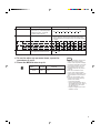
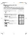
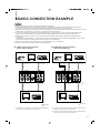
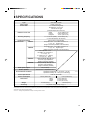
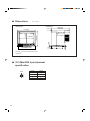
1
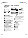
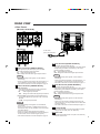
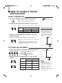
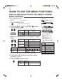
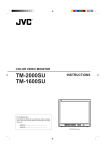
COLOR VIDEO MONITOR
INSTRUCTIONS
TM-A13SU
TM-A13UCV
TM-A13SU-W
For Customer Use:
Enter below the Model No. and Serial No. which is located
on the rear of the cabinet. Retain this information for future
reference.
–
Model No. :
Serial No.
PHASE
CHROMA
BRIGHT CONTRAST
MENU
+
VOLUME/SELECT
B
A
ON
OFF
INPUT SELECT
POWER
:
(TM-A13SU shown)
TM-A13SU
Thank you for purchasing this JVC color video monitor. Before using it, read and follow all
instructions carefully to take full advantage of the monitor's capabilities.
SAFETY PRECAUTIONS
WARNING :
FCC INFORMATION (U.S.A. only)
TO PREVENT FIRE OR SHOCK HAZARDS, DO NOT
EXPOSE THIS MONITOR TO RAIN OR MOISTURE.
CAUTION: Changes or modification not approved by
JVC could void the user's authority to operate the
equipment.
CAUTION :
To reduce the risk of electric shock, do not remove cover.
Refer servicing to qualified service personnel.
This monitor is equipped with a 3-blade grounding-type
plug to satisfy FCC rule. If you are unable to insert the
plug into the outlet, contact your electrician.
NOTE: This equipment has been tested and found to
comply with the limits for a Class B digital device,
pursuant to Part 15 of the FCC Rules. These limits are
designed to provide reasonable protection against
harmful interference in a residential installation. This
equipment generates, uses and can radiate radio
frequency energy and, if not installed and used in
accordance with the instructions, may cause harmful
interference to radio communications. However, there is
no guarantee that interference will not occur in a
particular installation. If this equipment does cause
harmful interference to radio or television reception,
which can be determined by turning the equipment off
and on, the user is encouraged to try to correct the
interference by one or more of the following measures:
– Reorient or relocate the receiving antenna.
– Increase the separation between the equipment and
receiver.
– Connect the equipment into an outlet on a circuit
different from that to which the receiver is connected.
– Consult the dealer or an experienced radio/TV
technician for help.
■ PRECAUTIONS
■ HANDLING
● Use only the power source specified on the unit.
(120 V AC, 50/60 Hz)
● Keep flammable material, water, and metal objects away
from the unit – especially the interior of the unit.
● This unit incorporates high voltage circuitry.
For your own safety and that of your equipment, do not
attempt to modify or disassemble this monitor.
There are no user-serviceable parts inside.
● Unplug the monitor when you’re not going to be using it for a
long period.
● Avoid shocks or vibrations. These may damage the unit
and cause it to malfunction.
● Do not block the ventilation slots.
● Do not expose this unit to high temperatures.
Extended exposure to direct sunlight or a heater could
deform the cabinet or cause the performance of internal
components to deteriorate.
● Do not place the unit near appliances generating strong
electric or magnetic fields. There can generate picture
noise and instability.
● Keep the monitor clean by wiping the cabinet and CRT
screen with a piece of soft cloth. Do not apply thinner or
benzine. These chemicals can damage the finish and
erase printed letters. When the unit is excessively dirty, use
a diluted neutral cleanser, then wipe away the cleanser
with a dry cloth.
SCREEN BURN
● It is not recommended to keep a certain still image displayed on screen for a long time as well as displaying extremely bright
images on screen. This may cause a burning (sticking) phenomenon on the screen of cathode-ray tube. This problem does not
occur as far as displaying normal video playback motion images.
2
CONTENTS
SAFETY PRECAUTIONS .......................................................................................... 2
CONTROLS AND FEATURES ................................................................................... 4
HOW TO HANDLE BASIC OPERATIONS ................................................................ 6
HOW TO USE THE MENU FUNCTIONS ................................................................... 7
HOW TO INITIALIZE THE SETTING ....................................................................... 10
BASIC CONNECTION EXAMPLE ............................................................................ 11
TROUBLESHOOTING ............................................................................................. 12
SPECIFICATIONS .................................................................................................... 13
3
CONTROLS AND FEATURES
FRONT VIEW
<Front Panel>
[TM-A13SU / TM-A13SU-W]
–
PHASE
CHROMA
BRIGHT CONTRAST
MENU
+
VOLUME/SELECT
B
A
ON
OFF
INPUT SELECT
POWER
(Front Panel view of TM-A13SU shown)
[TM-A13UCV]
–
PHASE
CHROMA
BRIGHT CONTRAST
MENU
+
VOLUME/SELECT
B
A
INPUT SELECT
_ON
—OFF
POWER
TM-A14PN
–
+
(Front view of TM-A13SU shown)
PHASE
CHROMA
BRIGHT CONTRAST
MENU
SELECT
B
A
ON
OFF
INPUT SELECT
POWER
1 Phase button [PHASE
2 Chroma button [CHROMA
TM-A13UCV
Notes:
]
Press this button to set the picture hue adjustment mode.
Adjust the value with the VOLUME/SELECT 6 or the
SELECT 7 buttons. Also used as a control button in the
menu function mode.
]
Press this button to set the picture color density adjustment mode. Adjust the value with the VOLUME/SELECT
6 or the SELECT 7 buttons. Also used as a control
button in the menu function mode.
3 Brightness button [BRIGHT
]
Press this button to adjust picture brightness. Adjust the
value with the VOLUME/SELECT 6 or the SELECT
7 buttons. Also used as a control button in the menu
function mode.
4 Contrast button [CONTRAST
]
Press this button to adjust picture contrast. Adjust the
value with the VOLUME/SELECT 6 or the SELECT
7 buttons. Also used as a control button in the menu
function mode.
5 Menu button [MENU]
Displays and disappears the <MENU> screen.
Pressing the PHASE button with the Menu button
depressed will display the <SET-UP MENU> screen.
6 Volume/Select buttons [VOLUME/
SELECT –
+] (TM-A13SU and TM-A13SU-W only)
Adjusts the speaker volume. Also used as a control button
in the menu function mode.
7 Select buttons [SELECT – /+] (TM-A13UCV only)
Used as a control button in the menu function mode.
8 Input B button [INPUT SELECT B]
Selects the video signal input to the VIDEO B terminal and
the audio signal input to the AUDIO B terminal (RCA
connector) on the rear panel. When selected, the input B
indicator @ lights.
4
TM-A13SU
* The VIDEO B terminals include a video terminal (BNC
connector) and a Y/C terminal (mini-DIN 4-pin connector).
The Y/C (S-video) terminal is given priority.
* There is no Y/C terminal or AUDIO B terminal on the TMA13UCV. They are only available on the TM-A13SU and
TM-A13SU-W.
9 Input A button [INPUT SELECT A]
Selects the video signal input to the VIDEO A terminal
(BNC connector) and the audio signal input to the AUDIO A
terminal (RCA connector) on the rear panel. When
selected, the input A indicator # lights.
Note:
* There is no AUDIO A terminal on the TM-A13UCV. It is
only available on the TM-A13SU and TM-A13SU-W.
10 Power indicator
Lights in green when the power is ON.
Lit : When the power is on.
Unlit : When the power is off.
11 Power switch [POWER
]
Press this switch to turn the power on or off.
_ ON : Power is turned on.
— OFF : Power is turned off.
12 Input B indicator
Lights in green when the Input B is selected.
13 Input A indicator
Lights in green when the Input A is selected.
14 Built-in speaker
(TM-A13SU and TM-A13SU-W only)
The speaker is located inside.
REAR VIEW
<Rear Panel>
[TM-A13SU / TM-A13SU-W]
VIDEO
A
IN
AUDIO
B
IN
OUT
A
Y/C IN
OUT
B
IN
OUT
VIDEO
A
IN
OUT
AUDIO
B
IN
OUT
A
Y/C IN
B
IN
OUT
[TM-A13UCV]
VIDEO
A
B
IN
IN
OUT
OUT
To AC outlet
(120 V AC, 50/60 Hz)
(Rear view of TM-A13SU shown)
17 Audio A terminal [AUDIO A IN/OUT]
15 Video A terminals [VIDEO A IN/OUT]
Video signal input (IN) and output (OUT) terminals.
The output terminal is bridge-connected.
IN : Video signal input terminal
OUT : Bridge-connected video signal output terminal
Notes:
* For corresponding audio signals, use the AUDIO A
terminals &.
* There is no AUDIO A terminal on the TM-A13UCV. It is
only available on the TM-A13SU and TM-A13SU-W.
* Also refer to the Basic connection Example on page 11.
16 Video B terminals [VIDEO B IN/OUT]
[ BNC connector ]
Video signal input (IN) and output (OUT) terminals.
The output terminal is bridge-connected.
IN
: Video signal input terminal
OUT : Bridge-connected video signal output terminal
[ Y/C connector ] (TM-A13SU and TM-A13SU-W only)
Y/C (S-Video) signal input (mini-DIN 4-pin connector)
terminal.
Y/C IN : Y/C signal input terminal.
Notes:
* For corresponding audio signals, use the AUDIO B
terminals *.
* There is no Y/C terminal or AUDIO B terminal on the
TM-A13UCV. They are only available on the TM-A13SU
and TM-A13SU-W.
* There is no Y/C (S-video) signal output terminal.
* When both VIDEO B terminals are connected (input) at
the same time, the Y/C terminal is given priority.
* Also refer to the Basic connection Example on page 11.
(TM-A13SU and TM-A13SU-W only)
Input (IN) and output (OUT) terminals for the audio signal
corresponding the VIDEO A terminals %. The output
terminal is bridge-connected.
IN : Audio signal input terminal
OUT : Bridge-connected audio signal output terminal
Notes:
* For corresponding video signals, use the VIDEO A
terminal %.
* There is no AUDIO A terminal on the TM-A13UCV. It is
only available on the TM-A13SU and TM-A13SU-W.
* Also refer to the Basic connection Example on page 11.
18 Audio B terminals [AUDIO B IN/OUT]
(TM-A13SU and TM-A13SU-W only)
Input (IN) and output (OUT) terminals for the audio signals
corresponding to the VIDEO B terminals ^. The output
terminal is bridge-connected.
IN
: Audio signal input terminal
OUT : Bridge-connected audio signal output terminal
Notes:
* For corresponding video signals, use the VIDEO B
terminals ^.
* There is no Y/C terminal or AUDIO B terminal on the
TM-A13UCV. They are only available on the TM-A13SU
and TM-A13SU-W.
* Also refer to the Basic connection Example on page 11.
19 AC Inlet [AC IN]
Power input connector. Connect the provided AC power
cord ) to an AC outlet (120 V AC, 50/60 Hz).
20 Power cord
Connects the provided power cord (120 V AC, 50/60 Hz)
to the AC IN connector.
5
HOW TO HANDLE BASIC
OPERATIONS
BASIC OPERATION
Color system indication
(NTSC or PAL )
1. Press the POWER switch to turn on the power.
_ON : Power turns ON. (Power indicator: lit)
—OFF : Power turns OFF. (Power indicator: unlit)
ON
OFF
NTSC
POWER
2. Press the INPUT SELECT button to choose input.
Selects video/audio signals input to terminals on the rear
panel.
B
A
INPUT SELECT
INPUT
SELECT
button
1 Input A
VIDEO A terminal
AUDIO A terminal
2 Input B
VIDEO B terminal
AUDIO B terminal
Terminals on the rear panel
Video signal input
Audio signal input
* Audio signal input is not available on the TM-A13UCV.
3. Press the VOLUME/SELECT button to adjust the
speaker volume.
(Audio is only available on the TM-A13SU and TM-A13SU-W.)
–
+
VOLUME/SELECT
(TM-A13SU / TM-A13SU-W)
Press this button to display the speaker volume level on the
screen.
+ : The Built-in speaker volume is increased. (00 = 50)
– : The Built-in speaker volume is decreased. (50 = 00)
* Screen indication will disappear about 10 seconds after
operating.
With regard to Color system indication
● With the COLOR SYSTEM setting set
to AUTO mode, when you turn on the
power or select inputs, the color
system indication appears for about 3
seconds on the screen while PAL or
NTSC signals are being detected.
It does not appear when receiving B/
W signal or when no signal is input.
See page 7 for COLOR SYSTEM
setting.
00 ~ 50
VOLUME
:
20
+
–
PICTURE ADJUSTMENT
–20 ~ +20
1. Press select button corresponding to the item you
want to adjust. The item you select is displayed on the screen.
PHASE
CHROMA
BRIGHT CONTRAST
1
2
3
4
PHASE (
) : Phase control
CHROMA ( ) : Chroma control
BRIGHT (
) : Brightness control
CONTRAST ( ) : Contrast control
2. Adjust with the VOLUME/SELECT or the SELECT
button.
–
+
VOLUME/SELECT
(TM-A13SU / TM-A13SU-W)
–
+
SELECT
(TM-A13UCV)
Items
VOLUME/SELECT button
–
+
PHASE
(Phase)
reddish
greenish
CHROMA
(Chroma)
lighter
deeper
BRIGHT
(Brightness)
darker
brighter
CONTRAST
(Contrast)
lower
higher
:
00
–
+
Notes:
* Screen indication will disappear about 10 seconds
after operating.
6
PHASE
● Phase control is effective only in the
NTSC color system mode.
● Chroma control is not effective when
receiving B/W or when no signal is
input.
● When the Chroma control is set to
level " –20", the picture turns
monochrome.
● " NO EFFECT" is displayed (For
about 3 seconds) when your selected
function has no effect.
HOW TO USE THE MENU FUNCTIONS
DISPLAY AND SELECTION IN THE <MENU> SCREEN
MODE (SETTING)
You can set the following menu items.
Set them depending on your needs.
• SHARPNESS
<MENU> screen
1
• COLOR SYSTEM
1. Press the MENU button.
< MENU >
‰ SHARPNESS
COLOR SYSTEM
: 00
: AUTO
3
2
The <MENU> screen is displayed.
MENU
2. Press the PHASE (
) or CHROMA (
to select MENU items.
) button
4
EXIT
A selection mark (3) is put next to the selected item.
PHASE
Front panel
button
CHROMA
SHARPNESS
PHASE (
CHROMA (
COLOR SYSTEM
–
Function
displayed
)
)
+
Contents
PHASE
▼
Advance selection mark (3)
5
Reverse selection mark (2)
CHROMA
BRIGHT CONTRAST
MENU
VOLUME/SELECT
<Front panel button>
3): Indicates the
1 Selection mark (3
menu item you select.
2 Menu item: Menu items you can
3. Press the VOLUME/SELECT or the SELECT button
to set.
–
+
VOLUME/SELECT
(TM-A13SU / TM-A13SU-W)
–
+
SELECT
Front panel
Function
button
displayed
VOLUME/
+
SELECT (+) or
3
SELECT (+)
VOLUME/
–
SELECT (–) or
2
SELECT (–)
the front panel buttons (7 buttons on
the left.) correspond to the function
displayed.
Contents
Increase (to max. value)
Function
displayed
Advance the setting value
Decrease (to min. value)
Reverse the setting value
Purpose
SHARPNESS
Picture sharpness
COLOR
SYSTEM
Color system
current settings (value).
4 Function display: The functions of
(TM-A13UCV)
Menu items
select.
3 Setting display: Indicates the
▼
Advance the menu item.
5
Reverse the menu item.
–
Lower the adjustment
value. (to the minimum)
+
Raise the adjustment
value. (to the maximum)
3
Advance the setting value.
Setting range
00
+1
AUTO
+2
NTSC
+3
+4
+5
PAL
* Normally set the COLOR SYSTEM to the AUTO mode. If reception in the AUTO mode is not good,
set it to the exclusive mode (NTSC or PAL) corresponding to the received color system.
Contens
2
Reverse the setting value.
EXIT
Exits the <MENU> screen.
4. If you want to set the other menu items, repeat
procedures 2 and 3.
5. Press the MENU button to quit.
MENU
Front panel
button
MENU
Function
displayed
Contents
EXIT
Quit (or Release) the <MENU>
screen
7
HOW TO USE THE MENU
FUNCTIONS (cont'd)
DISPLAY AND SELECTIONS IN THE <SET-UP MENU>
MODE (SETTING)
You can set the following set-up menu items.
● H. POSITION
● WHITE BALANCE
<SET-UP MENU> screen
● CONTROL LOCK
1
<SET–UP MENU>
‰ H. POSITION
: 00
WHITE BALANCE
CONTROL LOCK
: OFF
Note:
3
● Parameters for H. POSITION can be set separately depending on the video input (Input 2
A or Input B) selected by the input select buttons on the front panel.
Select the required video input with the input select buttons on the front panel in
advance.
4
EXIT
1. While pressing the MENU button, press the
) button.
PHASE (
–
PHASE
The <SET-UP MENU> screen is displayed.
PHASE
CHROMA
BRIGHT CONTRAST
MENU
+
VOLUME/SELECT
<Front panel button>
MENU
3): Indicates the
1 Selection mark (3
2. Press the PHASE (
) or CHROMA (
to select the desired menu item.
) button
menu item you select.
2 Menu item: Menu items you can
select.
3 Setting display: Indicates the
A selection mark (3) is put next to the selected item.
current settings (value).
4 Function display: The functions of
PHASE
CHROMA
H. POSITION
WHITE BALANCE
Front panel
button
PHASE (
CHROMA (
Function
displayed
)
)
Contents
▼
Advance selection mark (3)
5
Reverse selection mark (2)
CONTROL LOCK
+
button
displayed
+
VOLUME/SELECT
(TM-A13SU / TM-A13SU-W)
–
VOLUME/
SELECT (+) or
SELECT (+)
+
SELECT
(TM-A13UCV)
VOLUME/
SELECT (–) or
SELECT (–)
Contens
▼
Advance the menu item.
Reverse the menu item.
–
Lower the adjustment
value. (to the minimum)
+
Raise the adjustment
value. (to the maximum)
Increase (to max. value)
3
Advance the setting value.
Contents
3
Advance the setting value
2
Reverse the setting value.
CUTO
Selects CUT OFF setting
screen
EXIT
Exit the <SET-UP MENU>
screen (release)
–
Decrease (to min. value)
DRV
Selects DRV adjustment
2
Reverse the setting value
CUTO
DRV
Selects DRIVE setting screen
Notes:
● For the WHITE BALANCE setting, select the CUT OFF or
DRIVE setting screen, then select the buttons (PHASE/
CHROMA/BRIGHT) corresponding to the function indicated
(R/G/B).
● To return to the <SET-UP MENU> screen, press the EXIT
(MENU) button.
8
Function
displayed
5
3. Press the VOLUME/SELECT or the SELECT button
to set.
Front panel
Function
–
the front panel buttons (7 buttons on
the left.) correspond to the function
displayed.
Selects CUT OFF
adjustment
R
Adjusts red signal level
G
Adjusts green signal level
B
Adjusts blue signal level
DISP
Turns the ON-SCREEN
display on or off. (This
function is effective only in
the DRIVE or CUT OFF
adjustment mode.)
Set-up menu items
H. POSITION
WHITE BALANCE
DRIVE
Purpose
Settings
Adjusts the horizontal position of
the screen (+ : Horizontal position
shifts to the right/–: Horizontal
position shifts to the left)
Adjusts the white balance
–05
–04
••
–01
00
+01
••
+04
+05
Selects DRIVE (DRV) or CUT OFF (CUTO) adjustment.
Screen setting is changed to the selected setting mode.
Select R/G/B buttons corresponding to the function display
to adjust.
R.DRIVE
Adjusts red level
–09
–08
•••• ••
–01
00
+01
•••• ••
+08
+09
B.DRIVE
Adjusts blue level
–09
–08
•••• ••
–01
00
+01
•••• ••
+08
+09
Adjusts red cut off
–09
–08
•••• ••
–01
00
+01
•••• ••
+08
+09
G. CUT OFF
Adjusts green cut off
–09
–08
•••• ••
–01
00
+01
•••• ••
+08
+09
B. CUT OFF
Adjusts blue cut off
–09
–08
•••• ••
–01
00
+01
•••• ••
+08
+09
Sets the operation buttons on the
front panel to control lock mode
OFF
CUT OFF R. CUT OFF
CONTROL LOCK
ON
4. To set the other set-up menu items, repeat the
procedures 2 and 3.
5. Press the MENU button to quit.
Front panel
button
Function
displayed
Contents
EXIT
Quit (or Release) the <MENU>
screen
MENU
MENU
Notes:
● When the CONTROL LOCK function
is set to ON, pressing operation
buttons on the front panel will display
the message "CONTROL LOCK ON!"
on the screen for about 3 seconds.
● The CONTROL LOCK function is
maintained even when the power is
turned off.
● To turn off the CONTROL LOCK
function, while holding the MENU
button press the PHASE button. Then
set the CONTROL LOCK function to
OFF.
● Even when the CONTROL LOCK
function is set to ON, the following
operations are available:
– Power Switch operation.
– Sound volume adjustment with the
VOLUME/SELECT button. (Audio is
only available on the TM-A13SU
and TM-A13SU-W.)
– Display or disappear of the <SETUP MENU> screen.
9
HOW TO INITIALIZE THE
SETTING
SCREEN DISPLAY AND SELECTIONS IN THE <SET-UP
MENU> RESET MODE
You can set <MENU> and <SET-UP MENU> screen items, picture adjustment items and
the volume level to their factory-set (initial) values.
<SET-UP MENU> RESET screen
<SET–UP MENU> RESET
1. Press the Power (
OFF (—).
) Switch to turn the power
Are you
“Yes”
then
“No”
then
sure ?
<CONTRAST>
<+> or <–>
ON
OFF
POWER
)
The <SET-UP MENU> RESET screen is displayed.
Note:
ON
OFF
PHASE
MENU
POWER
● The <SET-UP MENU> RESET screen will not be
displayed if the MENU or PHASE buttons are pressed
for a very short time. Keep pressing them until the
display screen appears.
3. Setting
䢇 Initialization is required.
Press the CONTRAST ( ) button.
* When initialization is completed, and the <SET-UP
MENU> RESET screen disappears.
CONTRAST
䢇 Initialization is not required.
–
+
VOLUME/SELECT
(TM-A13SU / TM-A13SU-W)
–
+
SELECT
(TM-A13UCV)
10
Press the VOLUME/SELECT [+] or [–] button or the
SELECT [+] or [–] button.
* Initialization is aborted, and the <SET-UP MENU>
RESET screen disappears.
Initial settings
Volume Picture adjustment <SET-UP MENU> screen <MENU> screen Sorts
2. While pressing both MENU button and PHASE (
buttons, press the Power ( ) switch to turn the
power ON (_).
Functions (Items)
Initialization
(setting)
SHARPNESS
COLOR SYSTEM
00
AUTO
H. POSITION
WHITE BALANCE
R. CUT OFF
G. CUT OFF
B. CUT OFF
R. DRIVE
B. DRIVE
CONTROL LOCK
00
00
00
00
00
00
OFF
PHASE
CHROMA
CONTRAST
BRIGHT
00
00
00
00
VOLUME
20
* Volume is only available on the TMA13SU and TM-A13SU-W.
BASIC CONNECTION EXAMPLE
Notes:
● Before connecting your system, make sure that all units are turned off.
● The illustration below shows some examples of different connections. Terminal connections may differ depending on the
component connected. Be sure to refer to the instructions provided with the unit(s) you are connecting.
● Each pair of input (IN) and output (OUT) terminals are bridge-connected. However, the Y/C input terminal (Y/C IN) has no output
terminal (OUT) corresponding to it. (There is no Y/C terminal on the TM-A13UCV.)
● If you’re not connecting any equipment to a bridged output (OUT) terminal, be sure not to connect any other cables to the
bridged output (OUT) terminal as this will cause the terminating resistance switch to open (auto terminate function).
● When making a bridge connection, connect the input (IN) and output (OUT) terminals on the monitor to separate video
components.
(For example, if both terminals are connected to the same VCR, resonance may occur except during playback. This is caused
by the same video signal “looping” between the VCRs, and is not a malfunction.)
● Select the video input (Input A or Input B) with the input select button on the front panel.
● There is no Y/C terminal or AUDIO terminal on the TM-A13UCV.
7 VIDEO A Connection Example
(Select Input A button)
Video Camera
Video Monitor
VCR
Video Monitor
VCR
Video
Audio *1
Video
Y/C (S-video) *2
Audio *3
(Audio signal cable)
(Video signal cable)
(Y/C (S-video) signal cable)
(Audio signal cable)
VIDEO
OUT
Video Camera
(Video signal cable)
A
IN
7 VIDEO B Connection Example
(Select Input B button)
AUDIO
B
IN
OUT
A
Y/C IN
VIDEO
B
AUDIO
A
IN
B
IN
Y/C IN
IN
OUT
OUT
A
OUT
B
IN
OUT
Video
Audio *1
Video
Audio *3
(Video signal cable)
(Audio signal cable)
(Video signal cable)
(Audio signal cable)
Video Monitor
VCR
Video Monitor
: Signal Flow
*1 : Connection is only possible to the TM-A13SU and TM-A13SU-W.
There is no audio terminal on the TM-A13UCV.
VCR
: Signal Flow
*2 : Connection is only possible to the TM-A13SU and TM-A13SU-W.
There is no Y/C terminal on the TM-A13UCV.
*3 : Connection is only possible to the TM-A13SU and TM-A13SU-W.
There is no audio terminal on the TM-A13UCV.
11
TROUBLESHOOTING
Solutions to common problems related to your monitor are described here. If none of the solutions presented here
solves the problem, unplug the monitor and consult a JVC-authorized dealer or service center for assistance.
Note:
● Audio is only available on the TM-A13SU and TM-A13SU-W. It is not available on the TM-A13UCV.
Problems
Points to be checked
Measures (Remedy)
No power supply.
Is the power plug loosened or disconnected?
Firmly insert the power plug.
No picture with the
power on.
Is the video signal output from the connected
component?
Set the connected component correctly.
Is the input signal selected properly?
Select the required video signal input with the
Input select button. (See page 6.)
Is the video cable disconnected?
Connect the video signal cable firmly. (See page
11.)
Is the audio signal output from the connected
component?
Set the connected component correctly.
Is the volume output set to minimum?
Adjust the speaker volume with the VOLUME/
SELECT button. (See page 6.)
Is the audio cable disconnected?
Connect the audio signal cable firmly. (See page
11.)
Is the monitor close to a device generating a
strong magnetic field?
Move the device away from the monitor until the
picture stabilizes.
Is the color system selected properly?
Set the COLOR SYSTEM in the <MENU> screen
mode to [AUTO] mode. (See page 7.)
Has the picture control setting (CONTRAST,
BRIGHT, CHROMA or PHASE) been changed?
Set each picture control to the standard setting.
(See page 6.)
Is the monitor close to a speaker, magnet or any
other device generating a strong magnetic field?
Move the device away from the monitor and turn
the monitor’s power off. Wait at least 30 minutes,
then turn the power on again.
Are the operation buttons on the front panel
locked? ( Has CONTROL LOCK function set to
ON?)
Set the CONTROL LOCK to OFF in the <SETUP MENU> screen mode. (See pages 8 and 9.)
No sound.
(TM-A13SU and
TM-A13SU-W only)
Shaking picture.
The following are not malfunctions:
● When a bright still image (such as a white cloth) is displayed for a long period, it may appear to be colored. This is due to the
structure of the cathode ray tube and will be deleted when another image is displayed.
● You experience a mild electric shock when you touch the picture tube. This phenomenon is due to a normal buildup of static
electricity on the CRT and is not harmful.
● The monitor emits a strange sound when the room temperature changes suddenly. This is only a problem if an abnormality
appears on the screen as well.
● If two or more monitors are operated next to each other, their images may shake or be distorted. This phenomenon is due to
mutual interference; it is not a malfunction.
Move the monitors away from each other until the interference disappears or turn the power off on any monitor that is not being
used.
12
SPECIFICATIONS
MODEL
TM-A13SU / TM-A13SU-W
Color video monitor
Type
Color system
TM-A13UCV
NTSC (3.58), PAL
13" measured diagonally,
90° deflection, in-line gun,
vertical line trio type
(phosphor stripe pitch 0.64 mm)
Picture tube
Effective screen size
Width
Height
Diagonal
11-1/8" (280.8 mm)
8-3/8" (210.6 mm)
13-1/4" (335.4 mm)
Scanning frequency
H : 15.734 kHz (NTSC), 15.625 kHz (PAL)
V : 59.94 Hz (NTSC), 50 Hz (PAL)
Horizontal resolution
320 TV lines or more (NTSC)
Composite video: 1 line, BNC connector x 2,
1 Vp-p, 75 Ω negative sync
(bridge connection possible, auto termination)
Composite video: 1 line, BNC connector x 2,
1 Vp-p, 75 Ω negative sync
(bridge connection possible, auto termination)
Input terminals
VIDEO A
VIDEO B
Y/C-separated: 1 line,
mini-DIN 4-pin connector x 1
Y: 1.0 Vp-p, 75 Ω
C: 0.286 Vp-p, 75 Ω (NTSC),
0.3 Vp-p, 75 Ω (PAL)
AUDIO A
AUDIO B
Audio power output
Built-in speaker
Environmental conditions
Power requirements
Power consumption
Dimensions
Weight
Accessory
1 line (monaural), RCA pin x 2,
0.5 V rms, high-impedance
(bridge connection possible)
1 line (monaural), RCA pin x 2,
0.5 Vrms, high-impedance
(bridge connection possible)
1 W (monaural)
8 cm round x 1, impedance of 8 Ω
Operation temperature: 0 – 40 °C (32 – 104 °F)
Operation humidity: 20 – 80% (non-condensing)
120V AC, 50/ 60 Hz
0.87 A (120 V AC)
Width
Height
Depth
0.77 A (120 V AC)
14-1/2" (368 mm)
12-1/4" (310 mm)
14-3/4" (371.5 mm)
21.2 lbs (9.6 kg)
20.9 lbs (9.5 kg)
AC power cord [7.87 ft (2.4 m)] x 1
* Illustrations used in this manual are for explanatory purposes only. The appearance of the actual product may differ slightly.
* Dimensions and weight are approximate.
* E. & O. E. Design and specifications subject to change without notice.
13
7 Dimensions
Unit : Inch (mm)
< Side View >
< Front View >
14-3/4 (371.5)
1/16 (1.3)
14-1/2 (368)
14-5/8 (370)
BRIGHT CONTRAST
MENU
+
VOLUME/SELECT
B
A
ON
OFF
INPUT SELECT
POWER
TM-A13SU
13-1/4 (334) [Front foot]
11-7/8 (300) [Mid foot]
11-3/4 (296) [Rear foot]
3/4 (16)
3-5/8 (92) 4-7/8 (122.5)
1-16 (1)
CHROMA
1/8 (2)
*
11-3/8 (287)
–
PHASE
12-1/4 (310)
*
8-5/8 (217)
4-1/8 (102)
* Asterisks (∗) are used to indicate front panel
dimensions.
(TM-A13SU shown)
7 Y/C (Mini DIN 4 pin) terminal
specification
Pin No.
Y/C IN
14
4
3
2
1
Signal
1
GND (Y)
2
GND (C)
3
Y
4
C
15
TM-A13SU/TM-A13UCV/TM-A13SU-W COLOR VIDEO MONITOR
JVC PROFESSIONAL PRODUCTS COMPANY
DIVISION OF US JVC CORP.
1700 Vallery Road Wayne, NJ07470
JVC CANADA INC.
21 Finchdene Square, Scarborough Ontario M1X 1A7
© 1999 VICTOR COMPANY OF JAPAN, LIMITED
LCT0332-001B-H
0299-Tu-V-JMT