1
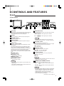
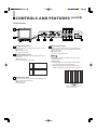
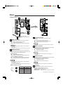
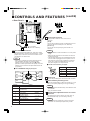
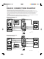
䊛
COLOR VIDEO MONITOR
INSTRUCTIONS
TM-910SU
CONTENTS
SAFETY PRECAUTIONS ................... 2
CONTROLS AND FEATURES............ 3
CONNECTION EXAMPLE .................. 7
TROUBLESHOOTING ........................ 8
SPECIFICATIONS .............................. 9
VOLUME
PHASE
CHROMA
BRIGHT
CONTRAST UNDER
SCAN
PULSE
CROSS
COLOR BLUE
OFF
CHECK
POWER
A
B
V.HOLD
PAL
EXT
SYNC
NTSC
NTSC
PAL
4:3
16:9
ON
OFF
For Customer Use:
Enter below the Serial No. which is located on the rear of the
cabinet. Retain this information for future reference.
Model No.
Serial No.
: TM-910SU
:
Thank you for purchasing this JVC color video monitor. To get the most from your new
high-performance monitor, please read this manual carefully beforehand.
SAFETY PRECAUTIONS
WARNING:
FCC INFORMATION (U.S.A. only)
TO PREVENT FIRE OR SHOCK HAZARDS, DO NOT
EXPOSE THIS APPLIANCE TO RAIN OR MOISTURE.
CAUTION: Changes or modifications not approved by
JVC could void the user’s authority to operate the
equipment.
NOTE: This equipment has been tested and found to
CAUTION:
To reduce the risk of electric shock, do not remove
cover.
Refer servicing to qualified service personnel.
䡵 PRECAUTIONS
● Use only the power source specified on the unit.
(120 V AC, 50/60 Hz or 12 V DC)
● Keep flammable material, water, and metal objects
away from the unit — especially the interior of the
unit.
● This unit incorporates high voltage circuitry which.
For your own safety and that of your equipment, do
not attempt to modify or disassemble this monitor.
There are no user-serviceable parts inside.
● Unplug the monitor when you’re not going to be using
it for a long period.
SCREEN BURN
● Try to avoid displaying still images or extremely
bright images on the screen for an extended period
of time. If left on screen for too long the image will
be permanently etched onto the CRT — a
phenomenon known as “screen burn”. Screen burn
is not a problem when displaying moving pictures
during video playback.
2
comply with the limits for a Class A digital device,
pursuant to Part 15 of the FCC Rules. These limits are
designed to provide reasonable protection against
harmful interference when the equipment is operated in a
commercial environment. This equipment generates,
uses, and can radiate radio frequency energy and, if not
installed and used in accordance with the instruction
manual, may cause harmful interference to radio
communications. Operation of this equipment in a
residential area is likely to cause harmful interference in
which case the user will be required to correct the
interference at his own expense.
䡵 HANDLING
● Avoid shocks or vibrations. These may damage the
unit and cause it to malfunction.
● Do not block the ventilation slots.
● Do not expose this unit to high temperatures.
Extended exposure to direct sunlight or a heater
could deform the cabinet or cause the performance
of internal components to deteriorate.
● Do not place the unit near appliances generating
strong electric or magnetic fields. These can
generate picture noise and instability.
● Keep the monitor clean by wiping the cabinet and
CRT screen with a piece of soft cloth. Do not apply
thinner or benzine. These chemicals can damage
the finish and erase printed letters. When the unit is
excessively dirty, use a diluted neutral cleanser, then
wipe away the cleanser with a dry cloth.
CONTROLS AND FEATURES
Front
<Front Panel>
1
11 12 13 14
VOLUME
PHASE
CHROMA
BRIGHT
CONTRAST UNDER
SCAN
PULSE
CROSS
COLOR BLUE
OFF
CHECK
POWER
A
B
2
V.HOLD
VOLUME
PHASE
CHROMA
BRIGHT
CONTRAST UNDER
SCAN
PULSE
CROSS
PAL
EXT
SYNC
NTSC
PAL
4:3
16:9
NTSC
ON
OFF
COLOR BLUE
OFF
CHECK
POWER
—A
_B
V.HOLD
PAL
EXT
SYNC
NTSC
PAL
4:3
16:9
NTSC
ON
OFF
3
4
1 Tally lamp
Indicates that a control signal is being received. The tally
lamp functions when the control signal is input to the
TALLY/REMOTE terminal on the rear panel.
2 Speaker
A built-in speaker is located inside the left side panel.
3 VOLUME control
Adjusts the speaker volume.
4 V.HOLD control
Use a small-bladed screwdriver to adjust the image’s
vertical stability.
5 Picture control section
PHASE, CHROMA, BRIGHT and CONTRAST controls
are available.
The standard setting mode can be obtained by setting
each control to the center click position. To adjust a
setting, insert a small-bladed screwdriver into the space
around the knob and turn it to the desired position.
When adjusting, use the small-bladed screwdriver and
insert it into the control hole around the required control
knob.
䡵 PHASE control
Adjusts picture hue.
䡵 CHROMA control
Adjusts picture color density.
䡵 BRIGHT control
Adjusts picture brightness.
䡵 CONTRAST control
Adjusts picture contrast.
Notes:
* The PHASE control is effective only in the NTSC color
system mode.
* The standard CHROMA setting can be adjusted to suit
the NTSC or PAL color system.
5
6
7
8
9
10
6 VIDEO A/B switch
Select the video signal input to the video input terminals
on the rear panel.
A (—) : Selects the video signal input to VIDEO A
terminal.
B (_) : Selects the video signal input to VIDEO B
terminal.
Note:
* VIDEO B terminals include both Y/C (S-Video) and
composite VIDEO terminals. Y/C inputs have priority.
7 EXT SYNC switch
Selects internal sync or external sync.
When using with the external sync, input the sync signal
to the EXT SYNC terminal on the rear panel.
(—) : Internal sync
(_) : External sync
8 NTSC/PAL switch
Selects the NTSC or PAL color system.
NTSC (—) : For NTSC color system.
PAL (_) : For PAL color system.
9 4 : 3/16 : 9 switch
Selects the aspect ratio (4:3 or 16:9) of the picture
displayed on the screen.
(—) : 4:3
(_) : 16:9
Note:
* When a 4:3 picture is viewed in the 16:9 mode, the size
of the image is reduced vertically.
10 POWER switch/POWER indicator
Press this switch to turn the power on or off.
ON (_) : Power is turned on and the power indicator
lights.
OFF (—) : Power is turned off and the power indicator
goes off.
Note:
* If the battery expires while the monitor is operated with
DC power supply (the voltage level drops), the green
indicator changes to orange, then to red. When the
POWER indicator changes to red, the power
automatically goes off. Make sure you switch off the
power before replacing the battery.
(continued on the next page =)
3
CONTROLS AND FEATURES
(cont'd)
<Front Panel>
11 12 13 14
1
VOLUME
PHASE
CHROMA
BRIGHT
CONTRAST UNDER
SCAN
PULSE
CROSS
COLOR BLUE
OFF
CHECK
POWER
A
B
2
V.HOLD
VOLUME
PHASE
V.HOLD
PAL
CHROMA
BRIGHT
CONTRAST UNDER
SCAN
PULSE
CROSS
EXT
SYNC
NTSC
PAL
4:3
16:9
NTSC
ON
OFF
COLOR BLUE
OFF
CHECK
POWER
—A
_B
NTSC
PAL
EXT
SYNC
NTSC
PAL
4:3
16:9
ON
OFF
3
4
11 UNDER SCAN switch
Selects the scanning mode (over scan screen or under
scan screen).
(—) : Over scan screen
(_) : Under scan screen
12 PULSE CROSS switch
Checks the retrace period (sync signal) by delaying the
input signal.
(—) : Normal screen
(_) : Retrace period display screen
5
6
7
8
9
10
14 BLUE CHECK switch
Selects the screen mode (normal or monochrome blue
screen). Useful when you want to check the chroma and
phase adjustment.
(—) : Normal screen
(_) : Monochrome blue screen
Note:
* The PHASE adjustment is effective only in the NTSC
color system mode.
[How to adjust]
1. Select the monochrome blue screen mode and input
color bar signals in the order of brightness.
2. Adjust the CHROMA and PHASE controls until the
density and brightness of each blue bar are the same.
13 COLOR OFF switch
Selects the screen mode (color or B/W). Useful when you
want to check the white balance.
(—) : Color screen
(_) : B/W screen
Adjust the blue bars to the same
density and brightness.
4
Rear
< Rear Panel >
24
25
VIDEO A
IN
OUT
15
SET UP
VIDEO B
IN
VIDEO A
IN
OUT
OUT
CUT OFF
B
1
2
VIDEO B
IN
R
OUT
16
G
IN
IN
DRIVE
R
1
Y/C
Y/C
OUT
OUT
2
G
EXT SYNC
IN
AC IN
EXT SYNC
OUT
IN
OUT
17
AUDIO
IN
OUT
A
AUDIO
IN
OUT
B
DC IN
12V
18
A
NORMAL
AFC
B
FAST
+
TALLY/
REMOTE
-
NORMAL
AFC
FAST
22
20
21
To AC outlet
(120 V AC, 50/60 Hz)
23
15 VIDEO A terminals
Video signal input (IN) and output (OUT) terminals.
The output terminal is bridge-connected.
IN : Video signal input terminal
OUT : Bridge-connected video signal output terminal
TALLY/
REMOTE
17 EXT SYNC terminals
External sync signal input (IN) and output (OUT)
terminals.
The output terminal is bridge-connected.
IN : Input terminal for the external sync signal
OUT : Bridge-connected output terminal
Note:
* Also refer to the Basic Connection Example on page 7.
Notes:
* For corresponding audio signals, use the AUDIO A
terminals *.
* Also refer to the Basic Connection Example on page 7.
16 VIDEO B terminals
Video signal input (IN) and output (OUT) terminals for
both composite and Y/C-separated (S-Video) terminals.
Each output terminal is bridge-connected.
[BNC terminals]
IN : Video signal input terminal
OUT : Bridge-connected video signal output terminal
[Y/C (mini-DIN 4-pin) terminals]
IN : Y/C-separated (S-Video) signal input terminal
OUT : Bridge-connected Y/C signal output terminal
Notes:
* For corresponding audio signals, use the AUDIO B
terminals (.
* Y/C- terminal has priority.
* Also refer to the Basic Connection Example on page 7.
䡵 Y/C terminal pin layout
3
1
4
2
3
1
4
2
IN
Y/C
19
OUT
18 AUDIO A terminals
Input (IN) and output (OUT) terminals for the audio signal
corresponding to the VIDEO A terminals %.
The output terminal is bridge-connected.
IN : Audio input terminal
OUT : Bridge-connected output terminal
Note:
* For corresponding video signals, use the VIDEO A
terminals %.
19 AUDIO B terminals
Input (IN) and output (OUT) terminals for the audio signal
corresponding to the VIDEO B terminals ^.
The output terminal is bridge-connected.
IN : Audio input terminal
OUT : Bridge-connected output terminal
Note:
* For corresponding video signals, use the VIDEO B
terminals ^.
20 AFC switch
Pin No.
Signal
1
GND (Y)
2
GND (C)
3
Y
4
C
Selects the AFC (Automatic Frequency Control) time
constant for the horizontal sync circuit.
Correct the skewed portion of the picture.
NORM position : Normal mode
FAST position : Fast mode (fast: smaller time constant)
(continued on the next page =)
5
CONTROLS AND FEATURES
< Rear Panel >
24
(cont'd)
25
IN
SET UP
OUT
A
VIDEO A
IN
OUT
CUT OFF
B
1
B
2
VIDEO B
IN
R
OUT
NORMAL
G
AFC
DRIVE
R
FAST
IN
Y/C
1
21
OUT
2
G
EXT SYNC
IN
AC IN
TALLY/
REMOTE
OUT
AUDIO
IN
OUT
A
B
DC IN
12V
NORMAL
AFC
FAST
TALLY/
REMOTE
-
22 Power input connector
Supply power to either the AC IN or DC IN 12 V
connector.
+
22
To AC outlet
(120 V AC, 50/60 Hz)
23
[AC IN]
Connect the provided AC power cord between the AC IN
connector and an AC outlet (120 V AC, 50/60 Hz).
[DC IN 12 V]
Connect the 12 V DC power plug to the DC IN 12 V
connector.
Notes:
21 TALLY/REMOTE terminal
External control terminal (DIN 8-pin). Tally lamp, VIDEO
A/B (input selection), Under Scan, External Sync, 4:3/16:9
(aspect ratio), Pulse Cross, and Color Off modes can be
controlled from an external unit.
Note:
* When you’re controlling the monitor externally via the
TALLY/REMOTE terminal, set all corresponding
switches on the front panel to the OFF (—) position.
(Whichever switch is pressed first has priority so remote
switches may not function if the panel switches are ON
(_) position.)
䡵 TALLY/REMOTE terminal pin layout
* See your dealer for more information on 12 V DC power
supply.
* When both AC IN and DC IN connectors are used, the
AC input has priority.
* The DC power supply does not automatically take over
if an AC outlet is unplugged or the AC power is cut off
when both AC and DC power supplies are connected.
In this case, press the POWER switch to set to OFF,
then press it again to turn the power ON.
䡵 DC IN 12 V connector pin layout
DC IN
12V
Pin No.
Signal
1
GND
2
—
3
—
4
12 V DC
3
GND
OFF
COLOR OFF
OFF
ON
UNDER
SCAN
1
4:3
2
TALLY
OFF
EXT
SYNC
24 External battery mounting holes
Attach an external battery to either pair of holes (1 or 2) to
use 12 V DC power (depending on the type of battery).
B
6
23 Power cord
Connect the provided power cord to the AC IN connector.
ON
A
Pin No.
1
ON
4
16:9
INPUT
SELECT
2
OFF
8
3
5
ASPECT
RATIO
4
ON
6
7
OFF
ON
PULSE
CROSS
Signal
1
TALLY lamp
ON/OFF
2
Input Select
(VIDEO A/B)
A/B
3
UNDER SCAN
ON/OFF
4
EXT SYNC
(External Sync)
ON/OFF
5
ASPECT RATIO
(4 : 3 /16 : 9)
4 : 3 /16 : 9
6
PULSE CROSS
ON/OFF
7
COLOR OFF
ON/OFF
8
GND
Notes:
* External batteries manufactured by Anton Bauer or PAG
are available.
* See your dealer for details.
25 Switch/control adjustment holes for service
personnel
For adjustment of SET UP switch, CUT OFF (B, R, G)
control and DRIVE (R, G) control during servicing.
Note:
* These controls are exclusively for the use of service
personnel. Do not attempt to adjust them yourself.
BASIC CONNECTION EXAMPLE
* Before connecting your system, make sure that all units are turned off.
* The illustration below shows some examples of different connections. Terminal connections may differ depending on the
component connected. Be sure to refer to the instructions provided with the unit(s) you are connecting.
* Each pair of input (IN) and output (OUT) terminals are bridge-connected. Do not connect input and output terminals inversely.
* If you're not connecting any equipment to a bridged output (OUT) terminal, be sure not to connect any other cables to the
bridged output (OUT) terminal as this will cause the terminating resistance switch to open (auto terminate function).
* When making a bridge connection, connect the input (IN) and output (OUT) terminals on the monitor to separate video
components.
(For example, if both terminals are connected to the same VCR, resonance may occur except during playback. This is caused
by the same video signal “looping” between the VCRs, and is not a malfunction.)
* Select the video input (VIDEO A or VIDEO B) with the VIDEO A/B switch on the front panel.
䡵 VIDEO A Connection Example
(Select VIDEO A input)
VIDEO A
IN
Video
OUT
Video
(Video signal cable)
(Video signal cable)
VIDEO B
IN
OUT
Video Camera
Sync Signal Generator
IN
VCR
Y/C
OUT
Video Monitor
EXT SYNC
IN
Sync
(Sync signal cable)
(Sync signal cable)
AUDIO
Audio
VCR
External Controller
(Ext. Control Switch)
OUT
Sync
IN
OUT
Video Monitor
Audio
(Audio signal cable)
A
(Audio signal cable)
B
TALLY/REMOTE
(Tally/Remote cable)
NORMAL
AFC
: Signal Flow
FAST
TALLY/
REMOTE
䡵 VIDEO B Connection Example
(Select VIDEO B input)
VIDEO A
IN
OUT
VIDEO B
IN
OUT
Video
Video
(Video signal cable)
(Video signal cable)
Video Camera
Y/C (S-Video)
IN
(Y/C (S-Video) signal cable)
Y/C
S-VHS VCR
Y/C (S-Video)
OUT
(Y/C (S-Video) signal cable)
Sync
EXT SYNC
(Sync signal cable)
IN
OUT
Sync
(Sync signal cable)
Video Monitor
AUDIO
IN
OUT
A
Video Monitor
B
Sync Signal Generator
S-VHS VCR
External Controller
(Ext. Control Switch)
(Audio signal cable)
Audio
(Audio signal cable)
Audio
NORMAL
AFC
TALLY/REMOTE
FAST
(Tally/Remote cable)
TALLY/
REMOTE
: Signal Flow
7
TROUBLESHOOTING
Solutions to common problems related to your monitor are described here. If none of the solutions
presented here solves the problem, unplug the monitor and consult a JVC-authorized dealer or service
center for assistance.
Problems
No power supply.
Points to be checked
Measures
Is the AC or DC power plug loosened or
disconnected?
Firmly insert the power plug.
Is the battery fully charged (when using DC
power)?
Charge the battery, or replace it with a charged
battery. (Refer to the instructions provided with the
battery.)
Is the video signal output from the connected
component?
Set the connected component correctly.
Is the input signal selected properly?
Select the required video signal input with the
VIDEO A/B switch. (See page 3.)
Is the video cable disconnected?
Connect the video signal cable firmly. (See page 7.)
Is the audio signal output from the connected
component?
Set the connected component correctly.
Is the volume output set at the minimum position?
Adjust the VOLUME control. (See page 3.)
Is the audio cable disconnected?
Connect the audio signal cable firmly. (See page 7.)
Shaking picture.
Is the monitor close to a device generating a
strong magnetic field (motor, transformer, etc.)?
Move the device away from the monitor until the
picture stabilizes.
No color, wrong
color, or dark picture.
Is the color system selected properly?
Set the color system correctly with the NTSC/PAL
switch. (See page 3.)
Is the COLOR OFF switch set properly?
Set the COLOR OFF switch to the OFF (—) position.
(See page 4.)
Has the picture control setting (CONTRAST,
BRIGHT, CHROMA or PHASE) been changed?
Set each picture control to the standard setting
(center) position. (See page 3.)
Unnatural, irregularly
colored, or distorted
picture.
Is the monitor close to a speaker, magnet or any
other device generating a strong magnetic field?
Move the device away from the monitor and turn
the monitor’s power off. Wait at least 30 minutes,
then turn the power on again.
Dark stripes at the
top and bottom of the
screen, picture
vertically squeezed.
Is the aspect ratio set to 16:9 (_)?
Press the 4:3/16:9 switch to restore the normal 4:3
mode (—). (See page 3.)
Picture flows.
Is the EXT SYNC switch set properly?
Set the EXT SYNC switch properly. (See page 3.)
Front panel switches
do not function.
Is the monitor being controlled by an external
control unit via the TALLY/REMOTE terminal?
Set the control on the external unit of the same
function as that on the monitor’s front panel to the
OFF (—) position, or disconnect the unit from the
TALLY/REMOTE terminal. (See page 6 and 7.)
External control not
possible with the unit
connected to TALLY/
REMOTE terminal.
Is the switch on the front panel of the same
function as that on the external control unit to the
ON (_) position?
Set the control on the front panel of the same
function as that on the external control unit to the
OFF (—) position. (See pages 3, 4, 6 and 7.)
No picture with the
power on.
No sound.
The following are not malfunctions:
● When a bright still image (such as a white cloth) is displayed for a long period, it may appear to be colored. This is due to the
structure of the cathode ray tube and will be deleted when another image is displayed.
● You experience a mild electric shock when you touch the picture tube. This phenomenon is due to a normal buildup of static
electricity on the CRT and is not harmful.
● The monitor emits a strange sound when the room temperature changes suddenly. This is only a problem if an abnormality
appears on the screen as well.
8
SPECIFICATIONS
7 Type
7 Color system
7 Picture tube
7 Effective screen size
7 Scanning frequency
7 Horizontal resolution
7 Input terminals
VIDEO A
VIDEO B
AUDIO A
AUDIO B
: Color video monitor
: NTSC, PAL
: 9" measured diagonally,
flat-square type,
90° deflection, in-line gun,
vertical line trio type (phospher
stripe pitch 0.5 mm)
: Width
6-7/8" (175 mm)
Height
5-3/8" (137 mm)
Diagonal 8-3/4" (222 mm)
: (H) 15.734 kHz (NTSC)
15.625 kHz (PAL)
(V) 59.94 Hz (NTSC)
50 Hz (PAL)
: 280 TV lines or more (Y/C input
mode)
7 External sync
: Composite video:
1 line, BNC connector x 2,
1 Vp-p, 75 ¸, negative sync
(bridge connection possible,
auto termination)
: Composite video:
1 line, BNC connector x 2,
1 Vp-p, 75 ¸ negative sync
(bridge connection possible,
auto termination)
Y/C-separated:
1 line, mini-DIN 4-pin
connector x 2
Y: 1.0 Vp-p, 75 ¸
C: 0.286 Vp-p, 75 ¸ (NTSC)
0.3 Vp-p, 75 ¸ (PAL)
(bridge connection possible,
auto termination)
* Y/C priority when both
connected
: 1 line (monaural), RCA pin x 2
0.5 V rms, high-impedance
(bridge connection possible)
: 1 line (monaural), RCA pin x 2
0.5 Vrms, high-impedance
(bridge connection possible)
7 Dimensions
7 Tally/Remote
7 Audio power output
7 Built-in speaker
7 Environmental
conditions
7 Power requirements
7 Power consumption
7 Weight
7 Accessory
: Composite sync
1 line, BNC connector x 2
1 – 4 Vp-p, 75 ¸
(bridge connection possible,
auto termination)
: 1 line, DIN 8-pin x 1
: 1 W (monaural)
: 3-3/16" (8 cm) round x 1
impedance of 8 ¸
: Operation temperature:
0 – 40 °C (32 – 104 °F)
Operation humidity:
20 – 80% (non-condensing)
: 120 V AC, 50/60 Hz or 12 V DC
: 0.57A (120 V AC)
3.3A (12 V DC )
: Width 8-3/4" (222 mm)
Height 9-3/8" (236 mm)
Depth 12-1/2" (317 mm)
: Approx. 16.3 lbs (approx. 7.4 kg)
: AC power cord [approx. 7.9 ft
(approx. 2.4 m)] x 1
* Illustrations used in this manual are for explanatory purposes only. The appearance of the actual product may differ slightly.
* E. & O. E. Design and specifications subject to change without notice.
9
䡵 Dimensions
Unit : inch (mm)
< Side View >
< Front View >
12-1/2 (317)
8-3/4 (222)
PAL
CHROMA
BRIGHT
CONTRAST UNDER
SCAN
PULSE
CROSS
9 (227)
COLOR BLUE
OFF
CHECK
POWER
A
B
EXT
SYNC
NTSC
NTSC
PAL
4:3
16:9
ON
OFF
6-1/2 (164)
3/8 (7)
PHASE
V.HOLD
3/8 (7)
VOLUME
7-1/8 (178)
9-3/8 (236)
5-5/8 (140)
12-1/8 (305)
2-1/2 (63.5)
1-1/16 (1.3)
* Asterisks (*) are used to indicate front panel
dimensions.
10
8-3/4 (222)
11
TM-910SU COLOR VIDEO MONITOR
䊛
JVC PROFESSIONAL PRODUCTS COMPANY
DIVISION OF US JVC CORP.
1700 Vallery Road Wayne, NJ07470
JVC CANADA INC.
21 Finchdene Square, Scarborough Ontario M1X 1A7
䊚1999 VICTOR COMPANY OF JAPAN, LIMITED
Printed in Thailand
LCT0469-002A-H
0999-Tu-V-JMT