1
AV- 20N3
AV- 20NMG3
AV- 20NMG3B
SERVICE MANUAL
COLOUR TELEVISION
AV-20N3/AV-20N3/D
AV-20NMG3/AV-20NMG3B
/AV-20NMG3/-A
BASIC CHASSIS
CG
[ RM-C364GY ]
[ RM-C364 ]
CONTENTS
!
!
!
!
!
!
!
!
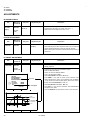
SPECIFICATIONS ・・・・・・・・・・・・・・・・・・・・・・・・・・・・・・・・ ・・・・・・・・・・・・・・・・・・・・・・・・・・・・・ 2
SAFETY PRECAUTIONS ・・・・・・・・・・・・・・・・・・・・・・・・・・・・・・・・・・・・・・・・・・・・・・・・・・・・・・・
・・・・・・・・・・・・・・・・・・・・・・・・・・・・・・・・・・・・・・・・・・・・・・・・・・・・・・・ 3
FEATURES・・・・・・・・・・・・・・・・・・・・・・・・・・・・・・・・
・・・・・・・・・・・・・・・・・・・・・・・・・・・・・・・・ ・・・・・・・・・・・・・・・・・・・・・・・・・・・・・・・・ ・・・ 4
FUNCTIONS ・・・・・・・・・・・・・・・・・・・・・・・・・・・・・・・・・・・・・・・・・・・・・・・・・・・・・・・・・・・・・・・・
・・・・・・・・・・・・・・・・・・・・・・・・・・・・・・・・・・・・・・・・・・・・・・・・・・・・・・・・・・・・・・・・ ・・ 5
MAIN DIFFERENCE LIST ・・・・・・・・・・・・・・・・・・・・・・・・・・・・・・・・
・・・・・・・・・・・・・・・・・・・・・・・・・・・・・・・・・・・・・・・・・・・・・・・・・・・・・・・
・・・・・・・・・・・・・・・・・・・・・・・ 7
SPECIFIC SERVICE INSTRUCTIONS ・・・・・・・・・・・・・・・・・・・・・・・・・・・・・・・・・・・・・・・・・・・・・
・・・・・・・・・・・・・・・・・・・・・・・・・・・・・・・・・・・・・・・・・・・・・ 8
SERVICE ADJUSTMENTS ・・・・・・・・・・・・・・・・・・・・・・・・・・・・・・・・ ・・・・・・・・・・・・・・・・・・・・・ 15
PARTS LIST ・・・・・・・・・・・・・・・・・・・・・・・・・・・・・・・・・・・・・・・・・・・・・・・・・・・・・・・・・・・・・・・・
・・・・・・・・・・・・・・・・・・・・・・・・・・・・・・・・・・・・・・・・・・・・・・・・・・・・・・・・・・・・・・・・ ・ 33
★ OPERATING INSTRUCTIONS
★ STANDARD CIRCUIT DIAGRAM ・・・・・・・・・・・・・・・・・・・・・・・・・・・・・・・・
・・・・・・・・・・・・・・・・・・・・・・・・・・・・・・・・・・・・・・・・・・・・・・・・
・・・・・・・・・・・・・・・・ 2-1
1
CO PYRIGHT © 2002 VICTOR COMPANY OF JAPAN, LTD.
No. 52025
Jun. 2002
AV-20N3
AV-20NMG3
AV-20NMG3B
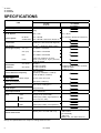
SPECIFICATIONS
CONT ENTS
ITEM
AV-20N3
AV-20N3/D
Dimensions(W×H ×D)
619mm ×458mm ×488mm
Mass
19kg
TV RF Syst em
B/G, I, D/K
B/G, I, D/K,M
RF Mode
PAL / SECAM
PAL / SECAM / NTSC3.58 / NTSC4 .43
VIDEO Mode
PAL / SECAM / NTSC3.58 / NTSC4 .43
Colour Syst em
Picture Tube
Visi bl e size: 48cm measured diagonally
High Voltage
26.5kV±1.5kV(at zero beam current)
Rec eiving Frequency
Interm ediate
Frequency
VHF (VL)
46.25MHz~168.2 5MHz
VHF (VH)
175.25MHz~463.2 5MHz
UHF
471.25MHz~863.2 5MHz
CATV
Cab le TVs of Mid ( X-Z, S1-S10)
Super (S11-S20) & Hyper (S21-S41)
bands recei vable
VIF Carrier
38.0MHz
SIF Carrier
32.5MHz (5.5MHz)
31.5MHz (6.5MHz)
32.0MHz (6.0MHz)
Colour Sub Carrier Frequency
PAL (4.43MHz),
SECAM (4.40625MHz / 4.25MHz)
NTSC (3.58MHz / 4.43MHz)
Power Input
AC110~240V, 50 / 6 0Hz
Rated Voltage
Power Consumption
90W (Max) / 60W(Avg)
Spe aker
5cm ×12 cm, O val type ×2
Audio Output
3W (monaural )
Aerial Input Terminal
75Ω Unbalanced
Input
Video
1V(p-p), 75Ω (Front / Rear )
Audio
500mV(rms) (-4dBs), Hi gh impedance,
RCA×2 (Front / Rear)
Video
1V(p-p), 75Ω
Audio
500mV( rms) (-4dBs), Low impedance,
Output
Hea dphone jack
3.5mm mini jack
Rem ote Control Unit
RM-C3 64GY
(Battery size : AA / R06 / UM-3×2)
Design and specifications are subject to change without notice.
2
AV-20NMG3
AV-20NMG3B
AV-20NMG3/-A
No. 52025
32.5MHz(5.5MHz) /33.5 MHz (4.5MHz)
31.5MHz (6.5MHz)
32.0MHz (6.0MHz)
[AV-20NMG3 / AV-20NMG3/-A]
: RM-C364G Y
[AV-20NMG3B]
: RM-C364
(Battery size : AA / R06 / UM-3×2)
AV-20N3
AV-20NMG3
AV-20NMG3B
SAFETY PRECAUTIONS
1. The design of this product contains special hardware, many
circuits and components specially for safety purposes. For
continued protection, no changes should be made to the original
design unless authorized in writing by the manufacturer.
Replacement parts must be identic al to thos e used in the original
circuits. Service should be performed by qualified pers onnel
only.
2. Alterations of the design or circuitry of the products should not be
made. Any design alterations or additions will void the
manufacturer's warranty and will further relieve the manufacturer
of responsibility for personal injury or property damage resulting
therefrom.
3. Many electrical and mechanical parts in the products have
special safety-related characteristics. T hese characteristics are
often not evident from visual inspection nor can the protection
afforded by them necessarily be obtained by using replacement
components rated for higher voltage, wattage, etc. Replacement
parts whic h have these special s afety characteristics are
identified in the parts list of Servic e manual. Electrical
components having su ch features ar e identified by shading
on the schematics and by (!
! ) on the parts list in Service
manual. The us e of a substitute replacement which does not
have the same safety characteristics as the recommended
replac ement part shown in the parts list of Service manual may
cause shock, fire, or other hazards .
4. Do n't shor t between the LIVE side ground and ISOL ATED
(NEUTRAL) side ground or EARTH side ground when
repairing.
Some model's power circuit is partly different in the GND. The
differenc e of the GND is shown by the LIVE : (") side GND, the
ISOLATED(NEUTRAL) : (#) side GND and EARTH : ($) side
GND. Don't short between the LIVE side GND and
ISOLATED(NEUTRAL) side GND or EARTH side GND and
never measure with a measuring apparatus (oscilloscope etc.)
the LIVE side GND and ISOLATED(NEUTRAL) side GND or
EARTH side GND at the s ame time.
If above note will not be kept, a fuse or any parts will be broken.
5. If any repair has been made to the chassis, it is recommended
that the B1 setting should be checked or adjusted (See
ADJUSTMENT OF B1 POWER SUPPLY).
9. Isolation Check
(Safety for Electrical Shock Hazard)
After re-ass embling the product, always perform an isolation
check on the exposed metal parts of the cabinet (antenna
terminals, video/audio input and output terminals, Control knobs,
metal cabinet, screwheads, earphone jack, control shafts, etc.)
to be sure the product is s afe to operate without danger of
electrical shoc k.
(1) Dielectric Strength Test
The isolation between the AC primary circuit and all metal parts
exposed to the us er, particularly any expos ed metal part having a
return path to the chass is should withs tand a voltage of 3000V
AC (r.m.s.) for a period of one sec ond.
(. . . . Withstand a voltage of 1100V AC (r.m.s.) to an applianc e
rated up to 120V, and 3000V AC (r.m.s.) to an appliance rated
200V or more, for a period of one second.)
This method of test requires a test equipment not generally found
in the servic e trade.
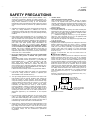
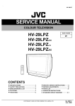
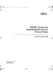
(2) Leakage Current Check
Plug the AC line c ord directly into the AC outlet (do not use a line
isolation transformer during this check.). Using a " Leakage
Current Tester", measure the leakage current from each exposed
metal part of the cabinet, particularly any expos ed metal part
having a return path to the chassis , to a known good earth
ground (water pipe, etc.). Any leakage current must not exceed
0.5mA AC (r.m.s.).
However, in tropic al area, this must not exceed 0.2mA AC
(r.m.s.).
" Alternate Check Method
Plug the AC line c ord directly into the AC outlet (do not use a line
isolation transformer during this check.). Use an AC voltmeter
having 1000 ohms per volt or more sens itivity in the following
manner. Connec t a 1500Ω 10W res istor paralleled by a 0.15µF
AC-type c apacitor between an exposed metal part and a known
good earth ground (water pipe, etc.). Meas ure the AC voltage
across the res istor with the AC voltmeter. Move the resistor
connec tion to each exposed metal part, particularly any exposed
metal part having a return path to the chassis, and measure the
AC voltage ac ross the res istor. Now, reverse the plug in the AC
outlet and repeat eac h measurement. Any voltage measured
must not exc eed 0.75V AC (r.m.s.). This c orresponds to 0.5mA
AC (r.m.s.).
However, in tropical area, this must not exceed 0.3V AC ( r.m.s.).
This corresponds to 0.2mA AC (r.m.s.).
6. The high voltage applied to the picture tube must conform with
that specified in Service manual. Excessive high voltage can
cause an increase in X-Ray emission, arcing and possible
component damage, therefore operation under excessive high
voltage conditions should be k ept to a minimum, or should be
prevented. If s evere arc ing occurs, remove the AC power
immediately and determine the cause by visual inspection
(incorrect installation, cracked or melted high voltage harness,
poor soldering, etc.). To maintain the proper minimum level of
soft X-Ray emission, c omponents in the high voltage circuitry
including the picture tube must be the exact replacements or
alternatives approved by the manufacturer of the c omplete
product.
AC VOLT MET ER
(HAVING 1000 Ω/V,
OR MOR E SENSIT IVITY)
0.15μF AC-T YPE
1500 Ω 10W
PLACE T HIS PROBE
ON EACH EXPOSED
MET AL PART
GOOD EARTH GROUND
7. Do not c hec k high voltage by drawing an arc. Use a high voltage
meter or a high v oltage probe with a VTVM. Discharge the
picture tube before attempting meter connection, by c onnecting
a clip lead to the ground frame and c onnecting the other end of
the lead through a 10kΩ 2W resistor to the anode button.
8. When service is required, observe the original lead dress. Extra
prec aution should be given to assure correct lead dress in the
high voltage circuit area. W here a s hort circuit has occurred,
those components that indicate evidence of overheating should
be replaced. Always use the manufacturer's replacement
components.
No.52025
3
AV-20N3
AV-20NMG3
AV-20NMG3B
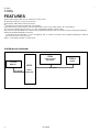
FEATURES
" New chassis design enables us e of an interactive on-screen c ontrol.
" Wide range voltage (110V~240V) AC power input.
" With AUDIO / VIDEO INPUT & OUTPUT terminal.
" MUTING button can reduce the audio level to zero instantly.
" Functional remote control to operate T V set (for channel select, volume c ontrol, power ON/OFF, etc.) from a distanc e.
" I2C bus control utilizes single chip ICs for IF, V/C, DEF. VSM PRESET, PRESET & SETUP TOUR.
" By means of AUTO PROGRAM, the TV s tations c an be s elected automatically and the TV channels can also be rearranged automatically.
" Built-in ECO MODE (ECONOMY, ECOLOGY)
In accordanc e with the brightness in a room, the brightness and / of contrast of the picture can be adjusted automatic ally to make the
optimum picture which is eas y on the eye.
" Built – in ON TIMER, RETURN + & CHILD LOCK.
SYSTEM BLOCK DIAGRAM
IC301
VIDEO/CHROMA
DECORDER
IC702
MEMORY
SCL 2/SDA2
4
IC701
SCL 1/SDA1
MICRO
COMPUTER
No. 52025
TU001
TUNER
AV-20N3
AV-20NMG3
AV-20NMG3B
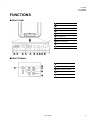
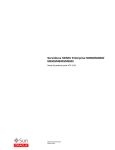
FUNCTIONS
■ FRONT PANEL
1 MENU buttons
2 CHANNEL -/+ buttons
3 VOLUME -/+ buttons
4 AI ECO sensor
5 REMOTE CONTROL s ens or
6 ON TIMER lamp
7 POWER lamp
8 MAIN POWER button
9 A/V INPUT terminal
10 HEADPHONE jack
10
9
1
2
3
4
5
6
7
8
■REAR TERMINAL
1 ANT Terminal
2
1
2 VIDEO INPUT Terminal
3
3 VIDEO OUTPUT Terminal
4
4 AUDIO INPUT T erminal
5 AUDIO OUT PUT Terminal
5
No. 52025
5
AV-20N3
AV-20NMG3
AV-20NMG3B
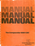
■ REMOTE CONTROL UNIT
RM-C364GY : AV-20N3 / AV-20N3 /D / AV-20NMG3 / AV-20NMG3/-A
RM-C364 : AV-20NMG3B
1 ECO SENSOR key
1
2 SOUND SYSTEM key
2
10
3
11
3 COLOUR SYSTEM key
4 TV/VIDEO key
4
5
5 OFF TIMER key
12
6 CHANNEL SCAN k ey
7 RETURN+key
6
7
13
8 DISPLAY key
8
14
9 CHANNEL key
15
10 POWER key
11 PICTURE MODE key
9
12 Number (CH.) key
16
13 -/--key
14 MUTING key
15 MENU key
MENU ▲/▼ key
MENU -/+ key
16 VOLUME-/+ key
Except for difference in body colour, the Remote Control
Unit RM-C364GY and RM-C364 have exactly the same
Func tions.
6
No. 52025
AV-20N3
AV-20NMG3
AV-20NMG3B
MAIN DIFFERENCE LIST
Part Name
Mai n PWB
Remote Control Unit
Fr ont Cabinet
Rating Label
AV-20N3
SCG -1403A-H2
RM-C3 64GY-1H
LC1 0438-027A-H
LC2 0377-010B-H
AV-20N3/D
SCG -1425A-H2
AV-20NMG3
SCG -1422A-H2
Model Name
LC1 0438-029A-H
AV-20NMG3B
RM-C3 64-1H
LC1 0438-033A-H
AV-20NMG3/-A
RM-C3 64GY-1H
LC1 0438-029A-H
Picture Tube
Inst Book
Di gest Manual
A48LWX10X
LCT1188- 001A- H
LCT1189- 001A- H
A48LDD095X
LCT1196- 001A- H
LCT1197- 001A- H
TV RF System
Col our System
[RF Mode]
Intermedi ate
Fr equency
[SIF Carri er ]
B/G, I, D/K
PAL / SECAM
Part Name
Model Name
AV-20N3
LC2 0413-002B-H
AV-20N3/D
AV-20NMG3
AV-20NMG3B
AV-20NMG3/-A
Item
Model Name
AV-20N3
32.5MHz (5.5MHz)
31.5MHz (6.5MHz)
OSD Language
E/R
32.0MHz (6.0MHz)
AV-20N3/D
AV-20NMG3
E/C/M/I
B/G, I, D/K,M
PAL / SECAM
NTSC3.58 / NTSC4.43
32.5MHz (5.5MHz)
33.5MHz (4.5MHz)
31.5MHz (6.5MHz)
32.0MHz (6.0MHz)
E /R/A/P
AV-20NMG3B
AV-20NMG3/-A
No. 52025
7
AV-20N3
AV-20NMG3
AV-20NMG3B
SPECIFIC SERVICE INSTRUCTIONS
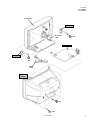
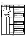
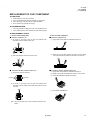
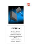
DISASSEMBLY PROCEDURE
REMOVING THE REAR COVER
1. Unplug the power plug.
2. As shown in figure, remove the
6
screws marked
!
and a
screw marked ".
3. Withdraw the rear cover toward you.
REMOVING THE MAIN PW BOARD
" After removing the rear cover.
1. Slightly raise the both sides of the MAIN PW BOARD by hand.
2. Withdraw the MAIN PW BOARD backward.
(If necess ary, take off the wire clamp, c onnectors etc.)
REMOVING THE SPEAKER
"
After removing the rear cover.
1. As shown in figure, remove the
2 screws marked # .
2. Follow the s ame steps when removing the other hand speak er.
CHECKING THE MAIN PW BOARD
1. To check the back side of the PW Board.
1) Pull out the MAIN PW Board. (Refer to REMOVING THE MAIN
PW Board)
2) Erect the PW Board vertic ally so that you can easily check the
back side of the PW Board.
[CAUTION]
" When erecting the PW Board, be careful s o that there will be no
contacting with other PW Board.
" Before turning on power, make sure that the CRT earth wire and
other connector are properly c onnected.
WIRE CLAMPING AND CABLE TYING
1. Be sure to clamp the wire.
2. Never remove the c able tie used for tying the wires together.
Should it be inadvertently removed, be sure to tie the wires with a
new cable tie.
8
No. 52025
AV-20N3
AV-20NMG3
AV-20NMG3B
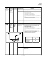
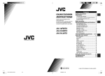
FRONT CABI.
SPEAKER
CRT SOCKET
PWB
C
(×
×2)
MAIN PWB
SPEAKER
C
(×
× 2)
POWER
CORD
REAR
COVER
B
A
No. 52025
(×
×1)
(×
×6)
9
AV-20N3
AV-20NMG3
AV-20NMG3B
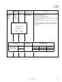
REPLACEMENT OF MEMORY ICs
1. MEMORY ICs
This model uses memory ICs. This memory IC data are for proper operation of the video and deflection circuits.
When replacing memory ICs, be sure to us e ICs written with the initial values of data.
2. PROCEDURE FOR REPLACING MEMORY ICs
(1) Power off
Switch the power off and disconnect the power plug from the wall outlet.
(2) Replace ICs
Be sure to use memory ICs written with the initial data values.
(3) Power on
Connect the power plug into the wall outlet and switch the power on.
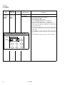
(4) Check and set SYSTEM CONSTANT SET
・ It must not adjust without adjustment signals.
1) Press the DISPLAY key and the PICTURE MODE key of the REMOTE
CONTROL UNIT simultaneously.
2) The SERVICE MENU screen of Fig. 1 will be displayed.
3) While the SERVICE MENU is displayed, again press the DISPLAY key and
PICTURE MODE key simultaneously, and the SYSTEM CONSTANT SET
screen of Fig. 2 will be displayed.
4) Check the setting values of the SYSTEM CONSTANT SET of T able 1 If the
value is different, select the s etting item with the MENU ▼/▲key, and s et
5)
(5)
(6)
(7)
the correct value with the MENU - / + k ey.
Press the DISPLAY key twice, and return to the normal screen.
Receive channel of setting
Refer to the OPERATING INST RUCTIONS and set the receive channels
(channels preset) as described
User Setting
Check the us er s etting value of Table 2, and if setting value is different, set
the correct value.
For setting, refer to the OPERATING INSTRUCTIONS.
Setting of SERVICE MENU
Verify the setting items of the SERVICE MENU, and reset where necessary.
For setting, refer to the SERVICE ADJUSTMENTS.
KEY ASSIGNMENT OF REMOTE CONTROL UNIT
SERVICE MENU
1.IF
2.V/C
3.DEF
4.VSM PRESET
5.PRESET
6.SETUP TOUR OFF
1-6 SELECT
****** *****
***
**
DISP : EXIT
** .***
** **
***
Fig.1
SYSTEM CONSTANT- Ⅰ
SYSTEM CONSTANT SET
COLOUR
BILINGUAL
TUNER
ECO SENSOR
LANGUAGE
/
: SELECT
- / + : OPERATE
1
: ***
:
:
:
:
NO
MU
YES
***
DISP : EXIT
SYSTEM CONSTANT-Ⅱ
Ⅱ
SYSTEM CONSTANT SET
2
B/B SOUND
: ***
LOCK
: 180
COLOUR AUTO
: ***
QSS
: MINT
ALC
: NO
TEXT RATE
: 20
: SELECT
/
- / + : OPERATE
DISP : EXIT
SYSTEM CONSTANT-Ⅲ
Ⅲ
PICT URE
MODE key
NUMBERS
key
SYSTEM CONSTANT SET
AMP TUNER
: NO
VNR
: YES
TEXT TABLE
: CYL
VOLUM PWM
: POS
: SELECT
/
- / + : OPERATE
DISPLAY
key
MENU
MENU
▼/▲ key
-/+key
Fig.2
Except for difference in body colour, the Remote Control
Unit RM-C364GY and RM-C364 have exactly the same
Func tions
10
DISP : EXIT
No. 52025
3
AV-20N3
AV-20NMG3
AV-20NMG3B
SETTING OF SYSTEM CONSTANT SET
Setting item
MULTI.
COLOUR
TRIPLE
YES
BILINGUAL
YES
E/R
E/C/M/I
OFF
10
MINT
YES
ALC
TEXT RATE
10
AMP TUNER
VNR
TEXT TABLE
VOLUM PW M
20
AV-20NMG3/-A
MULTI.
E/R
E/C/M/I
E/R/A/P
ON
OFF
~
20
YES
QSS
AV-20NMG3B
YES
250
COLOUR AUTO
TRIPLE
AV-20NMG3
NO
NO
ON
B/B SOUND
AV-20N3/D
MU
E/R/A/P
LANGUAGE
PAL
MA
YES
AI ECO SENSOR
AV-20N3
NO
MU
TUNER
LOCK
Setting value
Setting contents
230
240
180
NO
NO
MQSS
MINT
NO
NO
40
80
YES
20
YES
NO
YES
NO
YES
ARA
CYL
CYL
POS
NEG
NO
POS
Table 1
USER SETTING VALUES
Setting item
Setting value
Setting item
Setting value
SUB POWER
ON
LANGUAGE
ENGLISH
CHANNEL POSITION
1 POSITION
CHANNEL PRESET
Refer to OPERATING INSTRUCTION
VOLUME
About 10
AI ECO SENSOR
OFF
TV/VIDEO
TV
VNR
OFF
ON SCREEN DISPLAY
POSITION INDICATION
AUTO SHUTOFF
OFF
COLOUR SYSTEM
PAL
ON TIMER
PR1
SOUND SYSTEM
B/ G
BLUE BACK
OFF
OFF TIMER
OFF OSD.Shows 00
CHILD LOCK
OFF
PICTURE MODE (VSM)
BRIGHT
0:00
Table 2
No. 52025
11
AV-20N3
AV-20NMG3
AV-20NMG3B
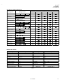
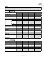
INITIAL SETTING VALUE OF SERVICE MENU
1.
Ad justment of the SERVICE MENU is m ade on the basis of the initial setting values ; however, the new setting values which
set the screen in its optim um condition may differ from the initial setting.
2.
Do no t change the initial Setting Values of the Setting (Adjustment) items not listed In “ADJUSTMENT”.
2. V/C
Colour system
Initial setting value
Variable
range
PAL
-128~+127
-50
-128~+127
+0
3. BRIGHT
-127~+127
+0
4. CONT .
-63~+63
+0
5. COLOUR
-63 ~+63
+0
Setting item
SECAM
NT SC 3.58
NT SC 4.4 3
+0
+0
+0
-2
+8
-2
RED
1. CUT OFF
GREEN
BL UE
RED
2. DRIVE
BL UE
TV
AV-20N3
AV-20N3/D
6. TINT
VIDEO
AV-20NMG3
AV-20NMG3B
AV-20NMG3/-A
+0
-31 ~+31
7. SECAM BL ADJ.
8. SHARP Do Not Adj.
-63~+63
TV
VIDEO
- 8(Fixed)
-32~+31
+15(Fixed)
3. DEFLECTION
Setting item
Initial setting value
Variable range
fv : 50Hz MODE
fv : 60Hz MODE
1. VER. POSITION
-04 ~ +03
-2
-3
2. HOR. POSITION
-16 ~ +15
+1
+4
3. VER. HEIGHT
-64 ~ +63
-40
+0
4. VER. L INEARITY
-32 ~ +31
+13
-3
5. VER. SWCURVE
-32 ~ +31
-32
+0
-63 ~ +62
+0
+0
BRIGHT
STANDARD
SOFT
+15
+11
6. HOR. VCO ADJUST
Do Not Adj.
4.VSM PRESET
VSM
Setting item
VSM pr eset
mode
TINT SETTING VALUE
+15
COLOUR SETTING VALUE
+15
BRIGHT SETTING VALUE
+15
CONT . SETTING VALUE
+30
SHARP SETTING VALUE
+15
12
+12
No. 52025
AV-20N3
AV-20NMG3
AV-20NMG3B
5. PRESET
The items in the following table, it is no requirem ent for adjustment.
If values had changed by the miss operation, set the initial setting values in the following table.
Colour System
Do Not Adjust
Initial setting value (Fixed value)
Setting item
PAL
SECAM
NT SC 3.58
NT SC 4.43
1. C TRAP FIX
1
1
1
1
2. SHARP PEAK
0
0
0
0
3. ABL
1
1
1
1
4. GAMMA
0
0
0
0
TV
0
2
2
3
VIDEO
0
2
0
2
+3
+3
+3
+3
TV
1
1
0
0
VIDEO
1
1
1
1
8. CW / SCP
0
0
0
0
9. VIF DET LEVEL
0
0
0
0
11. IF AGC MIN
0
0
0
0
12. VIF AGC
0
0
0
0
13. VIF PMOD
0
0
0
0
19. VNR
15
15
15
15
20. RGB LIM
1
1
1
1
21. RGB LIMIT LEVEL
2
2
2
2
23. TEXT H. POSITION
-3
-3
-3
-3
B/G
I
D/K
M
10. SIF DET LEVEL
+0
+0
+0
+0
14. SIF BPF BW ADJUST
+0
+0
+0
+0
15. SIF TRAP FO ADJUST
+0
+0
+0
+0
16. SIF TRAP FO ADJUST 2
+0
+0
+0
+0
17. SIF -TRAP
0
0
0
0
18. SIF -BPF
1
0
0
0
22. SIF SW
0
1
1
1
5. Y. DELAY TIME
6. BL ACK EXP START
7. C-BPF
24. READ DATA
Sound System
Do Not Adjust
Setting item
No. 52025
13
AV-20N3
AV-20NMG3
AV-20NMG3B
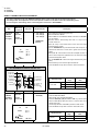
REPLACEMENT OF IC301 (IF V/C DECODER)
" For the IC301(IF V/C DECODER) of this model, all data are written in the micr o-computer. So, write the data in the microcomputer in accordance with the following procedures before starting adjustment.
PROCEDURES
(1) Turn the POWER OFF.
(2) Replace the IC301 with a new one.
(3) While pressing MENU button and VOL+ button ON the FRONT CABINET s imultaneous ly, turn the POW ER ON. When the POWER is
turned ON, the data is written in the micro-computer immediately.
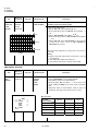
LOCATIONS OF FRONT PANEL BUTTONS AND LAM PS
1
MENU buttons
2
CHANNEL -/+buttons
・ / ・ buttons
(MENU -/+buttons)
・ / ・
buttons)
14
No. 52025
3
VOLUME - /+ buttons
(MENU -/+ buttons)
4
AI ECO sensor
5
REMOTE CONTROL sens or
6
ON TIMER lamp
7
POWER lamp
8
MAIN POW ER button
AV-20N3
AV-20NMG3
AV-20NMG3B
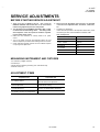
SERVICE ADJUSTMENTS
BEFORE STARTING SERVICE ADJUSTMENT
1. There ar e 2 way of adjusting this TV: One is with the
REMOTE CONTROL UNIT and the other is the conventional
method using adjustment parts and components.
2. The adjustment with the REMOTE CONTROL UNIT is made
on the basis of the initial setting values. The setting values
which adjust the screen to its optimum condition may differ
from the initial setting values.
3. Make s ure that connection is c orrectly made to AC power
sourc e.
4. Turn on the power of the set and equipment before us e, and
start the adjustment proc edures after waiting at least 30 minutes.
5. Unless otherwise spec ified, prepare the most suitable rec eption
or input signal for adjustment.
6. Never touch any adjustment parts, which ar e not specified
in the list for this adjustment VRs, transfor ms, condenser s,
etc.
7. Preparation for adjustment
Unless otherwis e specified in the adjustment instructions, preset
the following functions with the REMOTE CONTROL UNIT.
User mode position
PICTURE MODE (VSM)
BRIGHT
VNR
OFF
TINT / COLOUR / BRIGHT
CONT. / SHARP
CENTER
BLUE BACK
OFF
OFF TIMER
OFF
AI ECO SENSOR
OFF
AUTO SHUT OFF
OFF
MEASURING INSTRUMENT AND FIXTURES
1. DC voltmeter (or digital voltmeter)
2. Oscilloscope
3. Signal generator (Pattern generator) [PAL / SECAM / NTSC]
4. Remote control unit
ADJUSTMENT ITEMS
Ad justment item
Ad justment item
B1 POWER SUPPLY
DEFLECTION c ircuit adjustment
FOCUS adjustment
VSM PRESET s etting
IF circ uit adjustment
PURITY/ CONVERGENCE adjus tment
V/C (Video / Chroma) circuit adjustment
No. 52025
15
AV-20N3
AV-20NMG3
AV-20NMG3B
BASIC OPERATION OF SERVICE MENU
" The adjustment using SERVICE MENU
The following adjus tment items use the SERVICE MENU in the series of the adjustment. The adjustments are made on the bas is of the
initial setting values. The adjustment values which adjust the screen to the optimum condition c an be different from the initial setting values.
With the SERVICE MENU, various s ettings c an be made, and they are broadly classified in the following items of s ettings.
1.IF ・・・・・・・ ・・・・・・・・・・・・・ ・・・ Adjustment of the IF circuits.
2.V/C ・・・・・・・ ・・・・・・・・・・・・・ ・・ Adjustment of the VIDEO/CHROMA circuit.
3.DEF ・・・・・・・ ・・・・・・・・・・・・・ ・ Adjustment of the DEFLECTION circ uit.
4.VSM PRESET ・・・・・・・ ・・・・・ Adjustment of the initial setting values of VSM condition as STANDARD, SOFT and BRIGHT.
(VSM : Video Status Memory)
5.PRESET ・・・・・・・ ・・・・・・・・・・ Adjustment of the RF circ uit [Do not adjust].
6. SETUP TOUR OFF ・・・・・・・ It s hould be able to select mode (LANGUAGE and AUTO CH PRESET)..
[Shou ld be OFF].
" Key operation of the SERVICE MENU
[Enter to SERVICE MENU]
Press the DISPLAY key and the PICTURE MODE key of the REMOTE CONTROL
UNIT simultaneously. Then enter the SERVICE MENU mode as shown in Fig.1.
[Exit from SERVICE MENU]
When complete the adjustment work, press the DISPLAY key to return to the
SERVICE MENU.
And then press the DISPLAY key again, return to the normal screen.
SERVICE MENU
SERVICE MENU
1.IF
2.V/C
3.DEF
4.VSM PRESET
5.PRESET
6.SETUP TOUR OFF
1-6 SELECT
****** *****
***
[Select from SERVICE MENU]
In SERVICE MENU, press the number (1~6) key of the remote c ontrol unit, to select
any of the adjustment items.
The colours which selected item characters are changed.
KEY ASSIGNMENT OF REMOTE CONTROL UNIT
PICT URE
MODE key
NUMBERS
key
DISPLAY key
MENU
MENU
▼/▲ key
-/+key
Except for differenc e in body colour, the Remote Control Unit
RM-C364GY and RM-C364 have exactly the same Functions.
16
No. 52025
**
DISP : EXIT
**. ***
** **
Fig.1
***
AV-20N3
AV-20NMG3
AV-20NMG3B
[Method of setting]
1. IF
[1. VCO]
① 1 Key ・・・・・・・ ・・・・・・・・・・・・・ ・・・・・ Select 1.IF.
② 1 Key ・・・・・・・ ・・・・・・・・・・・・・ ・・・・・ Select 1.VCO
③ The VCO (CW) screen will be displayed a allow mark when the AFC voltage is at a certain level.
④ DISPLAY Key・・・・・・・ ・・・・・・・・・・・ As you press this key twice, you will return to the SERVICE MENU.
[2. DELAY POINT]
① 1 Key・・・・・・・ ・・・・・・・・・・・・・ ・・・・・ Select 1.IF.
② 2 Key・・・・・・・ ・・・・・・・・・・・・・ ・・・・・ Select 2.DELAY POINT.
③ MENU -/+ Key ・・・・・・・ ・・・・・・・・・・ Set (adjust) the setting values of the s etting items.
④ DISPLAY Key・・・・・・・ ・・・・・・・・・・・ When this is pressed twice, you will return to the SERVICE MENU.
2.V/C, 3.DEF and 4.VSM PRESET
① 2~4Key ・・・・・・・ ・・・・・・・・・・・・・ ・・・ Select one from 2. V/C, 3. DEF and 4. VSM PRESET.
② MENU ▼/▲ Key ・・・・・・・ ・・・・・・・ Select s etting items.
③ MENU -/+ Key ・・・・・・・ ・・・・・・・・・・ Adjust the values of the items.
④ DISPLAY Key ・・・・・・・ ・・・・・・・・・・・ When this is pressed, return to the SERVICE MENU.
6.SETUP TOUR
① By pressing the 6 key, you can change the ON or OFF ( should be OFF).
(Should be OFF)
%・ If it is ON, then you turn the TV power off, when you are turn the TV power on again.
The JVC’s logo will be shown about 15 s econds automatically.
② MENU -/+ Key ・・・・・・・ ・・・・・・・・・・ Select Language.
③ MENU ▼ Key ・・・・・・・ ・・・・・・・・・・ Auto Search.
No. 52025
17
AV-20N3
AV-20NMG3
AV-20NMG3B
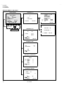
SERVICE MENU FLOW CHART
SERVICE MENU
SUB MENU 1. IF
SERVICE MENU
1.IF
2.V/C
3.DEF
4.VSM PRESET
5.PRESET
6.SETUP TOUR OFF
1-6 SELECT
****** *****
***
**
6.SETUP TOUR
DISP : EXIT
** .***
** **
IF
1. VCO
2. DELAY POINT
1-2 : SELECT
DISP : EXIT
***
OFF
ON / OFF
(By pressing 6-key)
DELAY POINT
SUB MENU 2. V/C
UHF
AGC TAKE-OVER
V/C
**
PAL
- / + : OPERATE
1. CUTOFF
(R) * **
(G) * **
(B) * **
50Hz
/
:SELECT
- / + : OPERATE
DISP : EXIT
SUB MENU 3. DEF
DEF
1. VER. POSITION
PAL
***
50Hz
/
:SELECT
- / + : OPERATE
DISP : EXIT
SUB MENU 4. VSM PRESET
BRIGHT
TINT
COLOUR
BRIGHT
CONT.
SHARP
/
:SELECT
- / + : OPERATE
**
**
**
**
**
DISP : EXIT
SUB MENU 5. PRESET
PRESET
PAL
1. C-TRAP FIX
50Hz
/
:SELECT
- / + : OPERATE
18
VCO (CW) ***.** MHz
TOO HIGH
ABOVE REFERENCE
JUST REFERENCE
BELOW REFERENCE
TOO LOW
** *(* *)
AFT ADJUST
** *(* *)
VCO ADJUST
FINE
DISP : EXIT
No. 52025
***
B/G
DISP : EXIT
DISP : EXIT
AV-20N3
AV-20NMG3
AV-20NMG3B
ADJUSTMENT LOCATIONS
CRT SOCKET PWB
(SOLDER SIDE)
TOP
U
TP-47R/G
TP-47G/R
TP-47B
TP-E
E1
T
CRT EARTH WIRE
(BRAIDED ASS'Y)
MAIN PWB
FRONT
F9 01
IC702
M EM ORY IC
IC701
PW
DEG
S
TU 001
S1
IC301
HV
T
U
HVT
1Pin TP-91(B1)
2Pin NC
3Pin X-ray1
4Pin X-ray2
5Pin TP-E( )
No. 52025
UPPER:FOCUS
LOWER:SCREEN
19
AV-20N3
AV-20NMG3
AV-20NMG3B
ADJUSTMENTS
B1 POWER SUPPLY
Item
Check of
B1 Power
Supply
Measuring
instrument
Signal
gener ator
Test point
Ad justment part
TP-91 ( B1)
TP-E (#
#)
Description
1. Input a whole black signal.
2. Connect a DC voltmeter to TP-91(B1) and TP-E (#).
3. Make sure that the voltage is DC116.5±2.0V.
DC Voltmeter
FOCUS ADJUSTMENT
Item
Ad justment
of FOCUS
Measuring
instrument
Test point
Signal
gener ator
Ad justment part
FOCUS VR
[In HVT]
Description
1. Input a cross-hatch s ignal.
2. While watching the s creen, adjust the FOCUS VR to make the
vertical and horizontal lines as fine and sharp as possible.
3. Make sure that when the screen is darkened, the lines remain in
good focus.
IF CIRCUIT ADJUSTMENT
Item
Ad justment
of VCO(CW)
Measuring
instrument
Test point
Signal
gener ator
Ad justment part
1. VCO
Remote
control unit
VCO (CW) ***.** MHz
TOO HIGH
ABOVE REFERENCE
JUST REFERENCE
BELOW REFERENCE
TOO LOW
** *(* *)
AFT ADJUST
** *(* *)
VCO ADJUST
FINE
DISP : EXIT
Description
●Please us e s ignal generator which is correct proof about the
sending frequency.
1.
2.
3.
4.
5.
6.
YELLOW
Do no t adjust
Input the PAL full colour bar (210.25MHz) signal.
Enter the SERVICE MENU.
Select 1.IF from the SERVICE MENU.
Press 1 key and s elect 1.VCO.
Select VCO ADJUST with MENU ▲/▼ key.
Press MENU -/+ k ey until the colour of the c haracters TOO
HIGH changes blue to yellow. Then gradually press the MENU
-/+ key until the TOO LOW changes yellow. At this time, confirm
that the value of VCO ADJUST is near +00.
7. Select AFT ADJUST with MENU ▲/▼ key.
8. Press MENU -/+ key until the characters JUST REFERENCE
changes blue to yellow.
9. Press the DISPLAY key three times to return to normal screen.
TOO HIGH
ABOVE REFERENCE
J US T R EFE RE NC E
BELOW REFERENCE
TOO LOW
ADJUST MENT AT T HIS POINT IS USELESS
20
ADJUST MENT POINT
No. 52025
AV-20N3
AV-20NMG3
AV-20NMG3B
Item
Ad justment
of DELAY
POINT
(AGC)
Measuring
instrument
Test point
Signal
gener ator
Ad justment part
DELAY POINT
(AGC TAKE-OVER)
Remote
control unit
DELAY POINT
DELAY POINT
Input a blac k and white signal (colour off).
Enter the SERVICE MENU.
Select 1. IF from the SERVICE MENU.
Select 2. DELAY POINT by pressing the 2 key on the remote
control unit.
5. Set the setting v alues of the setting items as shown bellow
table.
6. Then adjust the MENU - or + key until video noise disappears.
7. Turn to other channels and make sure that there are no
irregularities.
**
DISP : EXIT
Setting Item
(AGC TAKE OVER)
1.
2.
3.
4.
UHF
AGC TAKE-OVER
- / + : OPERATE
Description
Variable range
NT SC 3.58
Initial setting value
MATSUSHITA
(QAU0287-001)
MURATA
(QAU0185-004)
ALPS
(QAU0282-001)
45
45
45
35
45
35
0 ~127
OTHER
No. 52025
21
AV-20N3
AV-20NMG3
AV-20NMG3B
VIDEO / CHROMA CIRCUIT ADJUSTMENT
The setting (adjustment) usin g the REMOTE CONTROL UNIT is made on the basis of the initial setting values.
The setting values which adjust the screen to the optim um condition can be different fr om the initial setting valu es.
Do not change the initial setting values of the setting items not listed in “ADJUSTMENT”.
Item
Ad justment
of WHITE
BALANCE
(Low light)
Measuring
instrument
Test point
Signal
gener ator
Ad justment part
1. CUT OFF (R)
CUT OFF (G)
CUT OFF (B)
Remote
control unit
SCREEN VR
[IN HVT]
V/C
/
(R) * **
(G) * **
(B) * **
remote control unit.
5. Press the 1 key of the remote control unit to show the single
colours which except the appeared colour to where the single
horizontal line appears white.
8. Turn the SCREEN VR to where the single horizontal line glows
faintly.
9. Press the 2 key to turn off the single horizontal line.
50Hz
:SELECT
- / + : OPERATE
1. Input a blac k and white signal (colour off).
2. Enter the SERVICE MENU.
3. Select 2. V/C from the SERVICE MENU, then selec t 1. CUT OFF
(R), (G) and (B) .
4. Set eac h value to initial setting value with 4~ 9 keys of the
horizontal line on screen.
6. Turn the SCREEN VR fully counter-cloc kwise, then slowly turn it
clockwis e to where one of a red, blue or green colour is faintly
vis ible.
7. Use keys 4 ~9 of the remote control unit and adjust the other 2
PAL
1. CUTOFF
Description
DISP : EXIT
10.Press the DISPLAY key twic e to return to the normal screen.
KEY ASSIGNMENT OF REMOTE CONTROL UNIT
CUTOFF OFF
(H.LINE OFF)
1
2
3
4
5
6
7
8
9
CUTOFF ON
(H.LINE ON)
R. CUTOFF( ▲ )
Variable
range
Initial setting
value
R
-128~+127
-50
G
-128~+127
-50
B
-128 ~+127
-50
Ad justment item
B. DRIVE( ▲ )
R. CUTOFF( ▼ )
R. DRIVE( ▼ )
B. CUTOFF(
)
B. DRIVE( )
G.CUTOFF(
)
1. CUT OFF
▲
G
B
Signal
gener ator
2. DRIVE ( R)
DRIVE (B)
Remote
control unit
V/C
2. DRIVE
▲
R
Ad justment
of WHITE
BALANCE
(High light)
B. CUTOFF( ▲ )
▲
R. DRIVE( ▲ )
G.CUTOFF( ▲ )
PAL
1.
2.
3.
4.
Input a blac k and white signal (colour off).
Enter the SERVICE MENU.
Select 2. V/C from the SERVICE MENU.
Select 2. DRIVE (R) / (B) with MENU ▼/▲ key, and s et each
value to initial s etting value with 4 and 7 or 6 and 9 keys of the
remote control unit.
5. Use the keys 4 and 7 or 6 and 9 to produc e a white screen
6. Press the DISPLAY key twice to return to the nomal screen.
(R) * **
(B) * **
Variable
range
Initial setting
value
R
-128 ~+127
+0
B
-128~+127
+0
Ad justment item
/
50Hz
:SELECT
- / + : OPERATE
22
DISP : EXIT
2. DRIVE
No. 52025
AV-20N3
AV-20NMG3
AV-20NMG3B
Item
Ad justment
of
SUB BRIGHT
Measuring
instrument
Remote
control unit
Test point
Ad justment part
3. BRIGHT
Description
1.
2.
3.
4.
Receive any broadc ast.
Enter the SERVICE MENU.
Select 2. V/C from SERVICE MENU.
Select 3. BRIGHT with the MENU ▼/▲key.
5. Set the initial setting value with the MENU - / + key.
6. If the brightness is not the bes t with the initial set value, make
fine adjustment until you get the best brightness.
Ad justment
of
SUB CONT.
Remote
control unit
4. CONT .
1.
2.
3.
4.
Receive any broadc ast.
Enter the SERVICE MENU.
Select 2. V/C from SERVICE MENU.
Select 4. CONT. with the MENU ▼/▲key.
5. Set the initial setting value with the MENU - / + key.
6. If the contrast is not the best with the initial s et value, make fine
adjustment until you get the best contrast.
Ad justment
of
SUB
COLOUR Ⅰ
Remote
control unit
5. COLOUR
[Method of adjustm ent without m easuring instrument]
PAL COLOUR
1.
2.
3.
4.
5.
SECAM COLOUR
1. Receive a SECAM broadc ast.
2. Make fine adjustment of SECAM COLOUR as previously.
NT SC 3.58 COLOUR
1. Receive a NTSC 3.58MHz broadcast.
2. Make similar fine adjustment of NTSC 3.58 COLOUR as
previously.
NT SC 4.43 COLOUR
When NTSC 3.58 adjustment completed, NTSC 4.43 will be
automatic ally set at the respective values.
Receive a PAL broadc ast.
Enter the SERVICE MENU.
Select 2. V/C from the SERVICE MENU.
Select 5. COLOUR with the MENU ▼/▲ key.
Set the initial setting value for PAL COLOUR with the MENU
- / + key.
6. If the colour is not the best with the initial set value, make fine
adjustment until you get the best colour.
No. 52025
23
AV-20N3
AV-20NMG3
AV-20NMG3B
Item
Ad justment
of SUB
COLOUR Ⅱ
Measuring
instrument
Test point
Ad justment part
Description
Signal
gener ator
TP-47G/R
5. COLOUR
[Method of adjustm ent using measur ing instrument]
Oscilloscope
TP-E (#
#)
PAL COLOUR
1.
2.
3.
4.
5.
Input a PAL full field colour bar signal (75% white).
Enter the SERVICE MENU.
Select 2. V/C from SERVICE MENU.
Select 5. COLOUR with the MENU ▼/▲ key.
Set the initial setting value of PAL COLOUR with the MENU
- / + key.
6. Connect the osc illosc ope between TP-47G and TP-E (#).
7. Adjust PAL COLOUR to bring the value of (A) in the illustration
to the voltage as shown given billow.
(Voltage differenc e between (W) and (G))
[CRT SOCKET
PWB]
Remote
control unit
B
Mg
R
Model
(-)
W
0V
(A)
Y
Cy
(+)
G
SECAM COLOUR
Voltage(W-G)
AV-20N3
AV-20N3/D
+14V
AV-20NMG3
AV-20NMG3B
AV-20NMG3/-A
+10V
1. Input a SECAM full field colour bar signal (75% white).
2. Set the initial setting value of SECAM COLOUR with the MENU
- or + key.
3. Adjust SECAM COLOUR to bring the value of (A) in the
illustration to the voltage as shown given billow.
(Voltage differenc e between (W) and (G))
Model
NT SC 3.58 COLOUR
AV-20N3
AV-20N3/D
+8V
AV-20NMG3
AV-20NMGB
AV-20NMG3/-A
+10V
1. Input a NTSC 3.58 full field colour bar signal (75% white).
2. Set the initial s etting value of NTSC 3.58 COLOUR with the
MENU - / + key.
3. Adjust NTSC 3.58 COLOUR to bring the value of (A) in the
illustration to the voltage as shown given billow.
(Voltage differenc e between (W) and (G))
Model
NT SC 4.43 COLOUR
24
Voltage(W-G)
Voltage(W-G)
AV-20N3
AV-20N3 /D
+11V
AV-20NMG3
AV-20NMG3B
AV-20NMG3/-A
+10V
When NTSC 3.58 is set, NTSC 4.43 will be automatically set at the
respective values .
No. 52025
AV-20N3
AV-20NMG3
AV-20NMG3B
Item
Ad justment
of TINTⅠ
Ⅰ
Measuring
instrument
Test point
Ad justment part
Description
Signal
gener ator
6. TINT
[Method of adjustm ent without m easuring instrument]
Remote
control unit
NT SC 3.58 T INT
1. Input a NTSC 3.58 full field colour bar signal (75% white).
2. Enter the SERVICE MENU.
3. Select 2. V/C from SERVICE MENU.
4. Select 6. TINT with the MENU ▼/▲ key.
5. Set the initial setting value of NTSC 3.58 with the MENU - / +
key.
6. If you cannot get the best tint with the initial setting value, make
fine adjustment until you get the best tint.
Ad justment
of TINTⅡ
Ⅱ
Signal
gener ator
Oscilloscope
TP-47G/R
TP-E (#
#)
[CRT
SOCKET
PWB]
NT SC 4.43 TINT
When NTSC 3.58 is set, NTSC 4.43 will be automatically set at the
respective values .
6. TINT
[Method of adjustm ent using measur ing instrument]
NT SC 3.58 T INT
1. Input a NTSC 3.58 full field colour bar signal (75% white).
2. Enter the SERVICE MENU.
3. Select 2. V/C from SERVICE MENU.
4. Select 6. TINT with the MENU ▼/▲ key.
Remote
control unit
5. Set the initial setting value of NTSC 3.58 with the MENU - / +
key.
6. Connect the osc illosc ope between TP-47G/R and TP-E.
7. Adjust NTSC 3.58 TINT to bring the value of (B) in the
illustration to the voltage as shown given billow.
(Voltage differenc e between (W) and (Cy))
B
Mg
R
Model
(-)
W
(B)
Y
Cy
0V
(+)
G
NT SC 4.43 TINT
Voltage(W- Cy)
AV-20N3
AV-20N3 /D
+9V
AV-20NMG3
AV-20NMG3B
AV-20NMG3/-A
+9V
When NTSC 3.58 is set, NTSC 4.43 will be automatically set at the
respective values .
No. 52025
25
AV-20N3
AV-20NMG3
AV-20NMG3B
Item
Ad justment
of SECAM
BL ACK
OFFSET
Measuring
instrument
Test point
Remote
control unit
Ad justment part
7.SECAM
BL ADJUST
Description
[Method of adjustment using measur ing instrument]
1.
2.
3.
4.
5.
6.
Signal
gener ator
KEY ASSIGNMENT OF REMOTE CONTROL UNIT
Input a SECAM full field c olour bar signal.
Enter the SERVICE MENU.
Select 2. V/C from SERVICE MENU.
Select 7. SECAM BL ADJUST with ▼/ ▲MENU key.
Set the initial setting value with the – or + MENU key.
Switch the ①key (c olour OFF) and ②key (c olour ON) on the
remote control and make sure that there is no colour on the
blac k and white screen.
7. If the black and white s creen is not bes t with the initial setting
value, make fine adjustment until you get the best black and
white screen.
8. While watching the screen, adjust the value to be the same
colour between ON & OFF by ten key on the remote c ontrol
unit.
9. Press the DISPLAY key twice to return to the normal screen.
COLOUR
ON
1
2
3
4
5
6
7
8
9
COLOUR
OFF
26
No. 52025
AV-20N3
AV-20NMG3
AV-20NMG3B
DEFLECTION CIRCUIT ADJUSTMENT
" There are 2 modes of adjustment (s etting value) ------ ① 50Hz mode and ② 60Hz mode ----- depending upon the kind of s ignals
(vertic al frequency 50Hz / 60Hz).
" When adjusted in mode ① , mode ② will be automatically s et.
The setting (adjustmen t) usin g the REMOTE CONTROL UNIT is made on the basis of the initial setting values.
The setting values which adjust the screen to the optimum condition can be differ ent fr om the initial settin g values.
Item
Ad justment
of V.HEIGHT
&
V.POSITION
Measuring
instrument
Test point
Signal
gener ator
Ad justment part
1. VER. POSITION
3. VER. HEIGHT
Remote
control unit
SUB MENU 3. DEF
DEF
PAL
***
1. VER. POSITION
50Hz
/
:SELECT
- / + : OPERATE
Description
1.
2.
3.
4.
5.
6.
Input a circle pattern signal.
Enter the SERVICE MENU.
Select 3. DEF. from SERVICE MENU.
Select 1. VER. POSITION with the MENU ▼/▲ key.
Set the initial setting value with the MENU - / + key.
Adjust V and V’ to be equal with the MENU - / + key as s hown in
Fig.2.
7. Input a cross -hatch signal.
8. Select 3. V. HEIGHT with the MENU ▼/▲ key.
9. Set the initial setting value with the MENU - / + key.
10. As s hown in Fig.1, adjust VER. HEIGHT and mak e the vertical
screen size 92% of the picture size with the MENU - / + keys of
remote control unit.
DISP : EXIT
Scre en size
Scre en
size
Picture
size
10 0%
92%
Picture size 1 00%
Fig.1
Ad justment
of HOR.
POSITION
Signal
gener ator
2.HOR. POSITION
Remote
control unit
H
11. Input a circle pattern signal.
12. Select 2. HOR POSITION with the MENU ▼/▲ key.
13. Set the initial setting value of 2. HOR. POSITION with the
MENU - / + key.
14. Adjust 2. HOR. POSITION to make H=H" as shown in Fig.2
with the MENU - / + key.
H"
V
V'
Fig.2
No. 52025
27
AV-20N3
AV-20NMG3
AV-20NMG3B
Item
Ad justment
of VER. LIN.
& VER.
SCURVE
Measuring
instrument
Test point
Signal
gener ator
Ad justment part
4. VER. L IN.
5. VER. SCURVE
Remote
control unit
Description
● When
the
vertical
linearity
has
been
deteriorated
rem arkably, perform the following steps.
15. Input a cross -hatch signal.
16. Select 4. VER. LIN. with the MENU ▼/ ▲ key.
17. Set the initial s etting value of 4. VER LIN. with the MENU - / +
key.
18. Select 5. VER. SCURVE with the MENU ▼/▲ key.
19. Set the initial setting value of 5. VER. SCURVE with the MENU
- / + key.
20. Adjust 4. VER. LIN. and 5. VER. SCURVE so that the spaces
of each line as shown in Fig.3 on TOP, CENTER and
BOTTOM become uniform.
T OP
CEN TER
BOTT OM
Make sure that the adjustment is properly done on the screen of
60Hz mode.
[NOTE]
" Adjust to make both 50Hz & 60Hz are the same v. size and
fine straight line.
" When adjust again, adjust 50Hz mode first.
" When adjust in 60Hz mode, only 60Hz mode is adjust.
Fig.3
VSM PRESET SETTING
Item
Setting of
VSM
PRESET
Measuring
instrument
Test point
Remote
control unit
Ad justment part
TINT
COLOUR
BRIGHT
CONT .
SHARP
1.
2.
3.
4.
Enter the SERVICE MENU.
Select 4. VSM PRESET from the SERVICE MENU.
Select BRIGHT with the PICTURE MODE key.
Adjust the MENU ▼/▲ and MENU - / + key to bring the set
values of TINT ~ SHARP to the values shown in the below
table.
5. Respectively s elect the VSM PRESET mode for SOFT and
STANDARD, and make s imilar adjustment as in 3 above.
•
BRIGHT
TINT
COLOUR
BRIGHT
CONT.
SHARP
/
:SELECT
- / + : OPERATE
28
**
**
**
**
**
DISP : EXIT
Description
VSM PRESET
VSM
Setting Item
BRIGHT
STANDARD
SOFT
TINT
+15
COLOUR
+15
BRIGHT
+15
←
←
←
←
←
←
CONT
+30
+15
+11
SHARP
+15
←
+12
No. 52025
AV-20N3
AV-20NMG3
AV-20NMG3B
PURITY / CONVERGENCE ADJUSTMENT
PURITY ADJUSTMENT
1. Demagnetize CRT with the demagnetizer.
W EDGE
DEF LECT ION
YOKE
2. Loosen the retainer screw of the deflec tion yoke.
P
3. Remove the wedges.
CR T
4. Input a green raster signal from the signal generator, and turn
the screen to green raster.
46
P/C
MAGNET S
5. Move the deflection yoke backward.
# P/C MAGNETS
6. Bring the long lug of the purity magnets on the short lug and
position them horizontally. (Fig.2)
P : PURITY MAGNET
4 : 4 POLES (convergence magnets)
6 : 6 POLES (convergence magnets)
7. Adjust the gap between two lugs so that the GREEN RASTER
will come into the c enter of the screen. (Fig.3)
Fig.1
8. Move the deflection yoke forward, and fix the pos ition of the
deflection yoke so that the whole screen will bec ome green.
9. Ins ert the wedge to the top side of the deflection yoke so that it
will not move.
PURIT Y MAGNET S
Long lug
10. Input a cross hatch signal.
11. Verify that the screen is horizontal.
Short lug
12. Input red and blue raster signals, and make sure that purity is
properly adjusted.
Bring the long lug over the short lug
and position them horizontally.
Fig.2
(F RONT VIEW )
GREEN RASTER
CEN TER
Fig.3
No. 52025
29
AV-20N3
AV-20NMG3
AV-20NMG3B
STATIC CONVERGENCE ADJUSTMENT
1. Input a cross hatch signal.
2. Using 4-pole convergence magnets , overlap the red and blue
lines in the center of the screen (Fig.1) and turn them to
magenta (red/blue).
(F RONT VIEW )
3. Using
6-pole
convergence
magnets,
overlap
the
magenta(red/blue) and green lines in the center of the screen
and turn them to white.
4. Repeat 2 and 3 above, and make best c onvergence.
Fig.1
(F RONT VIEW )
DYNAMIC CONVERGENCE ADJUSTMENT
RED
GREEN BLUE
1. Move the deflec tion yok e up and down and overlap the lines in
the periphery. (Fig. 2)
BLUE
2. Move the deflection yoke left to right and overlap the lines in the
periphery. (Fig. 3)
RED
GREEN
GREEN
RED
BLUE
3. Repeat 1 and 2 above, and make best c onvergence.
BLUE
GREEN
RED
Fig.2
●
After adjustment, fix the wedge at the original position.
Fasten the retainer screw of the deflection yoke.
Fix the 6 magnets with glue.
(F RONT VIEW )
GREEN
RED
BLUE
GREEN
BLUE
RED
RED
GREEN
BLUE
BLUE
GREEN
RED
Fig.3
30
No.52025
AV-20N3
AV-20NMG3
AV-20NMG3B
REPLACEMENT OF CHIP COMPONENT
! CAUTIONS
1.
2.
3.
4.
Avoid heating for more than 3 seconds.
Do not rub the electrodes and the resist parts of the pattern.
When removing a c hip part, melt the s older adequately.
Do not reuse a chip part after removing it.
! SOLDERING IRON
1. Use a high ins ulation s oldering iron with a thin pointed end of it.
2. A 30w s oldering iron is rec ommended for easily removing parts.
! REPLACEMENT STEPS
1. How to remove Chip parts
$ Resistors, capacitors, etc
(1) As shown in the figure, push the part with tweezers and
alternately melt the solder at each end.
2. How to install Chip parts
$ Resistors, capacitors, etc
(1) Apply solder to the pattern as indic ated in the figure.
(2) Grasp the chip part with tweezers and plac e it on the s older.
Then heat and melt the solder at both ends of the chip part.
(2) Shift with tweezers and remove the chip part.
$ Transistors, diodes, variable r esistor s, etc
(1) Apply solder to the pattern as indic ated in the figure.
(2) Grasp the chip part with tweezers and place it on the solder.
$ Transistors, diodes, variable r esistor s, etc
(1) Apply extra solder to each lead.
(3) First s older lead A as indicated in the figure.
SOLD E R
SOLD E R
A
(2) As shown in the figure, push the part with tweezers and
alternately melt the solder at each lead. Shift and remove the
chip part.
B
C
(4) Then solder leads B and C .
A
B
Note : After removing the part, remove remaining solder from the
pattern.
No.52025
C
31
AV-20N3
AV-20NMG3
AV-20NMG3B
32
No.52025