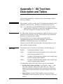
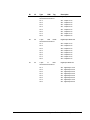
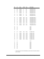
1
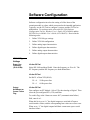
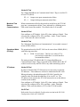
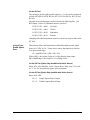
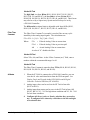
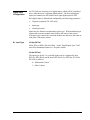
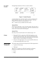
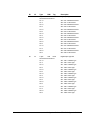
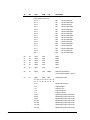
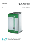
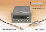
System 9100 Technical Manual 636.4 Configuration Guides Section Configuration Guide Issue Date 0896 XT-9100 Configuration Guide XT-9100 Extension Module/XP-910x Expansion Modules Page 3 • Introduction 3 • Hardware Configuration 4 • Model Codes 4 Software Configuration 7 • XT-9100 Type Settings 7 • XT-9100 Configuration 9 • Analog Input 10 • Digital Input Configuration 15 • Analog Output Configuration 16 • Digital Output Configuration 19 • Download/Upload 21 Appendix 1: SX Tool Item Description and Tables 23 • General 23 • Item Address 23 • Item Type 23 • Item Tag 24 • Read/Write Data (R/W) 24 • Floating Point Numbers 25 • Item List 25 © 1996 Johnson Controls, Inc. Code No. LIT-6364050 1 2 Configuration Guides—XT-9100 Configuration Guide XT-9100 Extension Module/ XP-910x Expansion Modules Introduction The XT-9100 Extension Module and its expansion modules have been designed to provide additional input and output capacity within Metasys Networks and specifically for the DX-9100 Extended Digital Controller. The XT-9100 module provides the communication interface and the XP modules provide the analog and digital inputs and outputs. A Supervisory System communicates with an XT-9100 via the N2 Bus or Bus 91*. Each XT-9100, depending on its expansion module combination, can have up to 16 inputs/outputs, eight of which may be analog. The DX-9100 communicates with the XT-9100 via the XT-Bus, and when the DX-9100 is connected to an N2 Bus (or Bus 91), data from the XT-9100 is available to a Supervisory System. Up to eight XT-9100 modules can be connected to the XT-Bus. Each XT-9100 provides, depending on the type of the connected XP expansion modules, either eight analog points or eight digital points, extending the input/output of a DX-9100 by up to 64 remote input/outputs. Modules with 16 input/outputs may also be connected, provided that the total number of remote input/output points on the DX-9100 does not exceed 64. Configuration of the XT-9100 is achieved by using a personal computer with GX-9100 Graphic Configuration Software (GX Tool) supplied by Johnson Controls. When the serial interface of the XT-9100 is connected directly to the N2 Bus (Bus 91), the GX-9100 will download and upload configurations over the N2 Bus (Bus 91). When the serial interface of the XT-9100 is connected to the XT Bus, the GX-9100 will download and upload configurations via the N2 Bus (Bus 91) connected to the DX-9100 to which the XT-Bus is connected. The DX-9100 retransmits configuration data to the XT-9100 on its XT-Bus. R S485 EXP A B CA B C EXP A I1 A I2 A I3 A I4 ADDRESS EX P +15V m ax AO 7 m in P ow er m ax AO 8 m in RD TD X T 9100 XP9102 F U SE C O M 24V A I5 A I6 V AO7 AO8 C 2 4V xt910x Figure 1: XT-9100 Extension Module and XP-910x Expansion Modules * The term “Bus 91” is not used in North America. Configuration Guides—XT-9100 Configuration Guide 3 Hardware Configuration For full details of the hardware configuration, refer to the XT-9100 Technical Bulletin (LIT-6364040). An XT-9100 combined with expansion modules provides the following configurations, either: • eight analog inputs/outputs, or • eight digital inputs/outputs, with digital counters associated with the digital inputs, or • eight analog inputs/outputs and eight digital inputs/outputs, or • sixteen digital inputs/outputs, with digital counters associated with the digital inputs within the first eight inputs/output points The extension module address is set with the address switches on the XT-9100. When connected to a DX-9100 controller, this address must also be set in the DX-9100 software configuration. The address must be unique not only on the XT-Bus, but also on the N2 Bus (Bus 91) to which the DX-9100 is connected. The XT-9100 must be supplied with a 24 VAC power source. All models are suitable for 50 Hz or 60 Hz through software configuration. For the analog inputs and outputs, the input and output type are set by jumpers on the analog expansion module board. These settings must comply with the software configuration settings. Note: When an extension module is configured with 16 inputs/outputs, the DX-9100 considers the single physical module as two logical modules, each with eight inputs/outputs. A DX-9100 can communicate with up to eight logical modules, with a maximum of 64 inputs/outputs. Model Codes Table 1: XT/XP/TR Model Codes XT-9100-8004 Extension Module 24 VAC supply XP-9102-8004 Expansion Module 6 analog inputs 2 analog outputs XP-9103-8004 Expansion Module 8 digital outputs (triacs) XP-9104-8004 Expansion Module 4 digital inputs 4 digital outputs (triacs) XP-9105-8004 Expansion Module 8 digital inputs XP-9106-8004 Expansion Module 4 digital outputs (relay) TR-9100-8001* Transformer, 24V/12 VA Primary: 240 VAC TR-9100-8002* Transformer, 24V/12 VA Primary: 220 VAC * TR-9100 is not available in North America. 4 Configuration Guides—XT-9100 Configuration Guide Bus Connector (provided) HOT GND RS485 NEUT EXP A B C A B C EXP C O M 24V TR EXP XP9102 FU S E C O M 24V XT A I5 A I6 V DO1 DO2 DO3 DO4 EXP DO1 DO2 DO3 DO4 DO5 DO6 DO7 DO8 max AO8 min RD TD XT9100 FUSE EXP +15V max AO7 min Power TR9100 AI1 AI2 AI3 AI4 ADDRESS XP9103 AO 7 AO8 C 24 V DO5 DO 6 DO 7 DO8 XP1 XP2 emtxt-4 Figure 2: Typical XT-9100 Configuration Table 2: XT Configurations TR Transformer TR-9100 XT Processor XT-9100 XP1 Analog XP-9102 (optional) (See Note 1.) or Digital XP-9103 XP-9104 XP-9105 Digital XP2 1 or 2 x XP-9106 (See Notes 2 and 4.) XP-9103 (optional) XP-9104 (optional) XP-9105 (optional) 1 or 2 x XP-9106 (optional) (See Notes 2, 3, and 4.) Notes: 1. The analog XP-9102 must be placed in position XP1. 2. Two XP-9106 modules are considered as one XP module when installed next to each other in Position XP1 or XP2. When a single XP-9106 is installed in Position XP1 and another type of XP module is installed in Position XP2, the total number of I/Os is restricted to 12. 3. The XP-9106 can only be placed in Position XP2 when Position XP1 is filled by an analog XP or two XP-9106 modules. 4. The first XP-9106 in position XP1 or XP2 controls points DO1-DO4 and the second XP-9106 in either position controls points DO5-DO8. 5. Digital modules with counters must be in position XP1. Configuration Guides—XT-9100 Configuration Guide 5 6 Configuration Guides—XT-9100 Configuration Guide Software Configuration Software configuration involves the setting of all the Items of the extension module to values which correspond to the intended application. Typically, use the GX Tool to configure a system, and the SX Tool to troubleshoot. To use these tools, refer to the GX-9100 Software Configuration Tool for Windows User’s Guide (LIT-6364060) and the SX-9100 Service Module User’s Guide (LIT-6364070). Proceed in the following order: 1. Define XT-9100 type settings. 2. Define XT-9100 configuration. 3. Define analog input characteristics. 4. Define digital input characteristics. 5. Define analog output characteristics. 6. Define digital output characteristics. XT-9100 Type Settings Power Line Frequency (50 or 60 Hz) Via the GX Tool Select DX-9100 and then Global. Enter the frequency as 50 or 60. The XT frequency and the DX frequency are both defined here. Via the SX Tool Set Bit X1 of Item XTS (RI.69). Output Hold/Reset on Comm. Failure Flag X1 = 0 50 Hz power line X1 = 1 60 Hz power line Via the GX Tool First configure an XT Module. Select XTn, then Analog or Digital. Then select the just configured XTn, XTn, and Data. To set this flag, at the “Status on comm. fail” (communication failure) field, enter 0 or 1. When this bit is set to “0,” the digital outputs are switched off upon a serial interface failure, and the corresponding Item values are reset to zero. When set to “1,” the digital outputs hold their current state upon a serial interface failure. Configuration Guides—XT-9100 Configuration Guide 7 Via the SX Tool The “Output Hold/Reset on Communication Failure” flag is set at Bit X2 of Item XTS (RI.69). Maximum Time Between Communications X2 = 0 Output reset upon communication failure X2 = 1 Output hold upon communication failure When communication fails for the period set in this Item, the XT-9100 goes into “communication failure” state, indicated by a blinking power LED on the front of the module. The default value is 60 seconds. Via the GX Tool First configure an XT Module. Select XTn, then Analog or Digital. Then select the just configured XTn, XTn, and Data. At the “Comm. timeout (sec)” field, enter the value in seconds. Via the SX Tool The “Maximum Time Between Communications” (in seconds) is entered at Item MTBC (RI.86). Operational Mode (SX Only) The operational mode of the XT-9100 can be seen at Item OPMO (RI.01) with following status bits: X8 = 1 PWR Power Failure. This bit is set when a XT is powered up or when there is a serial interface communication failure. The setting in Item XTS (RI.69) Bit X2 (“Output Hold/Reset on Communication Failure” flag) is repeated in Item OPMO (RI.01) Bit X7 so that it can be read by the DX-9100 or any other monitoring system. XT Address Via the GX Tool In order to download the XT-9100 devices it is necessary to enter the XT addresses. These addresses will also be loaded into the DX-9100. When performing a download through a DX-9100 Controller, the controller only downloads the addresses of its own XT set. The XT address is not stored in the XT-9100 but must be set on the address switches on the module. First configure an XT Module. Select XTn, then Analog or Digital. Then select the just configured XTn, XTn, and Data. At the “Hardware Address” field, enter the address (1-255) of the XT-9100 module. Via SX Tool Refer to the Extension Module Configuration section in the DX-9100 Configuration Guide (LIT-6364030). 8 Configuration Guides—XT-9100 Configuration Guide XT-9100 Configuration Settings Via the GX Tool The I/O type and map details are automatically generated by the GX-9100 Graphic Configuration Software when all I/O data for extension modules has been entered. It is then downloaded into the XT-9100 directly or via the DX-9100 and XT-Bus. (Refer to the Download/Upload section, further in this document.) When in the GX Tool, select the XT module, then define it as Analog or Digital (if Digital, define it as 8 DI, 4DI/4DO, or 8DO). This defines Module XP1. If an XT has 16 points (XP2 is connected), select the XT box immediately to the right of the configured module, select EXP.DIG and define it as 8DI, 4DI/4DO, or 8DO. “EXP” will appear in the XT box. Then select XT (or EXP) again and define each point in the selected configuration in the same way as when defining the points in the DX-9100. The following pages describe how to define each of the points individually. Via the SX Tool Each extension module configuration is defined by the I/O types and map which are configured in Extension Module Items IOMAP (RI.77), IOTYP (RI.78), and IOMOD (RI.79). 1. The I/O map (IOMAP) defines which inputs/outputs (in pairs) on the extension module are used. Each extension module can be defined with eight used points, which normally reside in the XP1 (first) Expansion Module (points I/O1-I/O8), defined in bits X1-X4. When an extension module has an XP2 (second) Expansion Module with a further eight points, these points must be defined in bits X5-X8. 2. The I/O type (IOTYP) defines which inputs/outputs (in pairs) are analog and which are digital. As the points on XP2 (if used) must be digital, only bits X1-X4 can be configured. 3. The I/O mode (IOMOD) defines points as “input” or “output” (in pairs). Only those points declared as “used” in Item IOMAP will be monitored or controlled. The combination of data in the Items IOMAP, IOTYP, and IOMOD completely defines the configuration of an extension module. When connected to a DX-9100 Controller, an identical set of data must be entered into the Item data base in the DX-9100 Controller, so that, when the DX-9100 and XT-9100 are connected and started up, the DX-9100 will compare data bases and only send commands to the extension module if the data is identical, thus avoiding incorrect control actions. Configuration Guides—XT-9100 Configuration Guide 9 Note: The data base in the XT-9100 has been designed to accept most configuration of inputs and outputs. All inputs and outputs which are physically connected through expansion modules must be configured, and only those points. If there is a difference between the physical configuration and the software configuration, the XT-9100 will signal an error condition to the DX-9100 (XTnERR). Analog Input Configuration Each analog input is defined and configured by the following parameters: • Tag name (optional, GX-only) • Measurement units (for RTD inputs) • Enable square root • Alarm on unfiltered value • Input signal range • Alarm limits • Filter time constant The GX Tool determines the input signal range with a 2-stage process: you must first decide if the input is active or passive; the remaining options depend on this choice. With the SX Tool, this information is entered into a number of Items. Via the GX Tool Select XTn, AIn, then either Active or Passive. Note: All AI points must be configured even if not connected to a sensor to enable the generation of a complete IO Map and to ensure correct operation with the DX-9100 Controller. AI Input Type: Measurement Units Via the GX Tool The selection of Celsius or Fahrenheit, is set in the Global data of the DX-9100 (select DX-9100, then Global. At the “Temperature Units” field, enter “C” for Celsius or “F” for Fahrenheit). To determine the measurement units of active inputs, select XTn, AIn, Data, and then enter in the “Measurement Units” field: 0 = None 1 = Temperature (“C” or “F” as entered in Global) 2 = Percent (%) Note: The units of an active input are not read by the DX-9100 Controller, but are available to any other Supervisory System which may be connected. 10 Configuration Guides—XT-9100 Configuration Guide Via the SX Tool The input type for the eight possible inputs (n = 1 to 8) can be configured in Item AITn (RI.88, RI.96, RI.104, RI.112, RI.120, RI.128, RI.136, and RI.144). The unit of each analog input can be selected with following bits: (For RTD inputs, Celsius or Fahrenheit must be selected.) X4 X3 X2 X1 = 0000 No Units X4 X3 X2 X1 = 0001 Celsius X4 X3 X2 X1 = 0010 Fahrenheit X4 X3 X2 X1 = 0011 Percent Changing individual temperature units for each AI can only be done in the SX Tool. AI Input Type: Enable Square Root This function allows the linearization of the differential pressure signal from a 0-10 VDC or 0/4 - 20 mA active sensor; the function is effective over the selected range: AI = sqrt(PR%/100) * (HR - LR) + LR Where %PR = the Analog Value in % of the physical input range; HR = High Range Value; and LR = Low Range Value. Via the GX Tool (Option Only Available with Active Sensor) Select XTn, AIn, and Data. At the “Square Root” field, enter “0” for No, or “1” for Yes (to enable the square root calculation). Via the SX Tool (Option Only Available with Active Sensor) Select Item AITn. X5 = 1 Enable Square Root of Input X5 = 0 Disable Square Root of Input Configuration Guides—XT-9100 Configuration Guide 11 AI Input Type: Alarm on Unfiltered Value An alarm from the High Limit (HIAn) and Low Limit Alarm (LOAn) will be generated from the unfiltered or filtered input. (See Filter Time Constant.) Via the GX Tool Select XTn, AIn, and Data. At the “Alarm Unfiltered” field, enter “0” for No (Alarm on Filtered Value), or “1” for Yes (Alarm on Unfiltered Value). Via the SX Tool Select Item AITn. AI Input Type: Input Signal Range X6 = 0 Alarm on Filtered Value X6 = 1 Alarm on Unfiltered Value Via the GX Tool (You must first have selected whether the input is active or passive. See the beginning of Analog Input--Configuration.) For active inputs, select XTn, AIn, then Data. At the “Type of Active Input” field, enter: 0= 0-10 VDC 1= 4-20 mA 2= 0-20 mA Each analog input module channel performs the conversion of the input signal to a numeric value using the high range and low range. Select XTn, AIn, then Data. High Range = enter the equivalent number for reading at high input (10V, 20 mA) Low Range = Enter the reading at low input (0V, 0 mA, 4 mA) For passive inputs, select XTn, AIn, then Data. At the “Type of Passive Input” field, enter: 1= Ni1000 (JCI Type) 2= Ni1000 Extended Range 3= A99 (JCI Type) 4= Pt 1000 (DIN) Note: Selections 5 and 6 on the screen are not available in the XT-9100. For RTD inputs, the range of the displayed value is fixed according to the type of sensor. 12 Configuration Guides—XT-9100 Configuration Guide Via the SX Tool Input Type: X7 = 0 0-10 volts X7 = 1 0-20 mA X8 = 1 20% suppression 2-10V or 4-20 mA) Linearization and Sensor Type: X11 X10 X9 = 000 Linear (Active Sensor) X11 X10 X9 = 001 Ni 1000 RTD Passive Sensor (JCI Type) (-45 to +121°C/-50 to +250°F) X11 X10 X9 = 010 Ni 1000 RTD High Temperature Sensor (+21 to +288°C/70 to +550°F) X11 X10 X9 = 011 RTD Sensor A99 (-50 to +100°C/-58 to +212°F) X11 X10 X9 = 100 RTD Sensor Platinum 1000 (+50 to +200°C/-58 to +320°F) For active inputs, each analog input module channel performs the conversion of the input signal to a numeric value using the high range at Item HRn (RI.89, RI.97, RI.105, RI.113, RI.121, RI.129, RI.137, and RI.145) and low range at Item LRn (RI.90, RI.98, RI.106, RI.114, RI.122, RI.130, RI.138, and RI.146). For RTD inputs, the range of the displayed value is fixed according to the type of sensor. AI Input Type: Alarm Limits The high limit and the low limit define at which levels the analog input reading will generate an alarm, either for remote monitoring or for internal use within the control sequences in the DX-9100. Note: The limits cannot be deleted. If you do not want alarms, enter limits beyond the range. Via the GX Tool Select XTn, AIn, then Data. At the respective field, enter the limit: High Limit = Low Limit = Limit Differential = Configuration Guides—XT-9100 Configuration Guide 13 Via the SX Tool The high limit is at Item HIAn (RI.91, RI.99, RI.107, RI.115, RI.123, RI.131, RI.139, and RI.147), the low limit is at Item LOAn (RI.92, RI.100, RI.108, RI.116, RI.124, RI.132, RI.140, and RI.148). These Items may also be set by a Supervisory System and will always be set by a DX-9100 Controller. The differential on alarm limits is adjustable with Item ADFn (RI.93, RI.101, RI.109, RI.117, RI.125, RI.133, RI.141, and RI.149). Filter Time Constant The Filter Time Constant Ts (seconds) is used to filter out any cyclic instability in the analog input signals. The calculations are: FVt = FVt-1 + [1/(1 + Ts)] * [AIt - FVt-1] Where: FVt = Filtered Analog Value at current time FVt-1 = Filtered Analog Value at previous poll AIt = Actual Analog Value at current time A value of “0” disables the filter. Via the GX Tool Select XTn, AIn, and Data. At the “Filter Constant (sec)” field, enter a number within the recommended range 0 to 10. Via the SX Tool The Filter Time Constant is entered at Item FTCn (RI.94, RI.102, RI.110, RI.118, RI.126, RI.134, RI.142, and RI.150). AI Notes 1. When the XT-9100 is connected to a DX-9100 Controller, you can view the AI value and alarm limits from the DX front panel. See Display Panel and Keypads in the DX-9100 Extended Digital Controller Technical Bulletin (LIT-6364020). 2. Analog input values can be read via the SX Tool at Item AIn (RI.12 to RI.19). 3. Analog input alarm status can be seen via the SX Tool at Item AIS (RI.11), Bit X1, X3....X15 for high alarm condition and X2, X4....X16 for low alarm condition. 4. Configure all AIs as Active or Passive, whether they are used or not. A configured AI is shown by a thick bar to the left and right of its selection box. 14 Configuration Guides—XT-9100 Configuration Guide Digital Input Configuration An XT-9100 can accept up to 16 digital inputs, which will be considered active when driven to a common digital ground. The first eight digital inputs are connected to XP1 and the next eight digital inputs to XP2. Each digital input is defined and configured by the following parameters: • Tag name (optional, GX-9100 only) • Input type • Counter prescaler Inputs may be defined as maintained or pulse type. With maintained type contacts the extension module status follows the status of the contact. With pulse type contacts the extension module sets and resets the status at each pulse of the input contact. DI: Input Type Via the GX Tool Select XTn (or EXP), DIn, then Data. At the “Digital Input Type” field enter 0 for maintained contact or 1 for pulse contact. Via the SX Tool The input type for the 2 x 8 possible inputs can be configured in Item DIT1 for XP1 (RI.64) and in Item DIT2 (RI.65) for XP2, bits X1-X8 for D11-DI8, as follows: 0 = Maintained Contact 1 = Pulse Contact Configuration Guides—XT-9100 Configuration Guide 15 DI: Counter Prescaler The digital input transitions of XP1 are counted as follows: Digital Input DIn Prescale PCn (RI.09) (RI.48-55) Count Transition Pulse Counter CNTRn (RI.32-39) emcmxt-3 Figure 3: Counter Prescaler A count transition occurs when the number of positive transitions of the digital input (DIn) equals the value of the prescaler (PCn). The Pulse Counter (CNTn) counts the count transitions (n = 1-8). Note: Counters are only available in the XP1 location. Via the GX Tool Select XTn, DIn, then Data. At the “Prescaler (counts)” field, enter from 1 to 255. When the XT-9100 is connected to a DX-9100 Controller the total counts can be read on the DX-9100 front panel. Via the SX Tool Enter the prescaler at Item PCn (RI. 48-55) within the range 1-255. DI Notes Analog Output Configuration 1. When the XT-9100 is connected to a DX-9100 Controller, you can view the DI status and counter values from the DX-9100 front panel. See the Display Panel and Keypads section in the DX-9100 Extended Digital Controller Technical Bulletin (LIT-6364020). 2. The status of the digital inputs can be seen at Item DIS1 (RI.09), bits X1-X8, and Item DIS2 (RI.10), bits X1-X8. Each analog output is defined and configured by the following parameters: • Tag name (GX-9100 only) • Output type When the XT is connected to a DX-9100 Controller, the following parameters are defined in the DX-9100 for the analog output: • Source • Range 16 Configuration Guides—XT-9100 Configuration Guide AO: Output Type Via the GX Tool Select XTn, ANALOG, XTn, AOn, and Data, then enter the output code: 0 = disabled 1 = 0 to 10 VDC 2 = 0 to 20 mA 3 = 4 to 20 mA Via the SX Tool The output type can be configured in Item AOT (RI.87) in bit pairs X2 X1, X4 X3, ...X16 X15 for Outputs 1-8). To define the output signal set the bits (for Output 7, for example) as follows: AO: Range (with DX-9100 only) X14 X13 = 00 Output Disabled X14 X13 = 01 Output 0-10V X14 X13 = 10 Output 0-20 mA X14 X13 = 11 Output 4-20 mA The AO range of the analog output is defined in the DX-9100 Controller. The High Range defines the level of control source signal that corresponds to an output of 100%. The Low Range defines the level of control source signal that corresponds to an output of 0%. When the source point is equal to the high range, then the output will be at the maximum signal (10V/20 mA). When the source point is equal to low range, then the output will be at the minimum signal (0V, 0/4 mA). Via the GX Tool Select XTn, AOn, and Data, then enter the desired values in the “High Range” and “Low Range” fields. Via the SX Tool Refer to the Extension Module Configuration section of the DX-9100 Configuration Guide (LIT-6364030). Configuration Guides—XT-9100 Configuration Guide 17 AO: Source (with DX-9100 Only) The source of the analog output signal is defined in the DX-9100 Controller. Via the GX Tool Select XTn, AOn, Data, and the “Source Point” field. Enter * and select the required source variable. Via the SX Tool Refer to the Extension Module Configuration section of the DX-9100 Configuration Guide (LIT-6364030). AO Notes 1. When the XT-9100 is connected to a DX-9100 Controller, you can view and override the AO value from the DX-9100 front panel. See Display Panel and Keypads in the DX-9100 Extended Digital Controller Technical Bulletin (LIT-6364020). 2. The analog output values can be read in percent at Item AOn (RI.20-27) with the SX Tool. 18 Configuration Guides—XT-9100 Configuration Guide Digital Output Configuration Each digital output is defined and configured by the following parameters: • Tag name (GX-9100 only) • Output type • Pulse time When the XT is connected to a DX-9100 Controller, the following parameter is defined in the DX-9100 for the digital output: • DO: Type of Output Source Via the GX Tool Select XTn (or EXP) and DOn, then select either of the On/Off or Pulse fields. For the Pulse type, the output switches for a configurable pulse time for each state transition of the command output. Via the SX Tool The output type for outputs DO1-DO8 can be selected in Item DOT1 (RI.66) for XP1 and Item DOT2 (RI.67) for XP2 as follows: X1 = 0 On/Off Type (Maintained) X1 = 1 Pulse Type; the output switches for a configurable pulse time for each state transition of the command output DO: Pulse Time This parameter is set once for all pulse type outputs in the XT-9100. Via the GX Tool Select XTn, XTn, and Data, then enter a value in the “Digital Output Pulse Time” field. The valid range is 1 to 250 (5 msec to 1.25 seconds pulse time). Via the SX Tool The digital output pulse time can be defined in Item DOPT (RI.68) in units of 5 msec. The default value is 200, which represents a pulse time of 1 second. Note: All connected DO points must be configured to ensure correct operation with the DX-9100 Controller. When a single XP-9106 (4DO) relay module is connected, select 8 DO on the GX Tool and define outputs DO1-DO4 only. Configuration Guides—XT-9100 Configuration Guide 19 DO Source (with DX-9100 Only) The source of the digital output signal is defined in the DX-9100 Controller. Via the GX Tool Select XTn or (EXP), DOn, Data, and then the “Source Point” field. Enter * and select the required source variable. Via the SX Tool Refer to the Extension Module Configuration section in the DX-9100 Configuration Guide (LIT-6364030). DO Notes 1. When the XT-9100 is connected to a DX-9100 Controller, you can view and override the DO value from the DX-9100 front panel. See Display Panel and Keypads in the DX-9100 Extended Digital Controller Technical Bulletin (LIT-6364020). 2. The digital output status can be seen at Item DOS1 (DI.07) for XP1 and Item DOS2 (DI.08) for XP2, bits X1-X8 for outputs DO 1-8 with the SX Tool. 3. A configured DO is shown by a thick bar to the left and right of its selection box. Configure all DOs as ON/OFF or PULSE, whether they are used or not. The only exception is for the 4-output relay module (XP-9106). When only one XP-9106 module is installed, select 8DO, but only configure DO1-DO4. When two XP-9106 modules are installed, configure both as one 8DO module, and configure DO1-DO8. 20 Configuration Guides—XT-9100 Configuration Guide Download/ Upload Via the GX Tool Download via DX-9100 Controller and N2 Bus Connect an RS-232-C/RS-485 converter (type MM-CVT101-x in North America and type IU-9100-810x in Europe) to one of the serial communication ports (COM1 or COM2) of the personal computer on which the GX Tool is running. Connect the N2 Bus of the DX-9100 to the converter unit connected to the PC. Set the address switches and jumpers on the DX-9100 and XT/XP devices as required, and connect the XT/XP devices to the XT Bus of the DX-9100. (See the DX-9100 Extended Digital Controller Technical Bulletin (LIT-6364020) and XT-9100 Technical Bulletin (LIT-6364040) for details.) If the DX-9100 and XT/XP devices are installed and wired, verify all field wiring and sensor voltage/current signals. It is recommended that controlled devices be isolated during download and initial startup. Note: Do not download an untested configuration into an installed device. Test the configuration on a simulator panel before downloading. Apply 24 VAC power to the DX-9100 and XT/XP devices. On the GX Tool, select DX-9100, DOWNLD, and DX. Enter the DX-9100 address (0-255) in the “Controller Address” field and the PC serial communication port (1 or 2) in the “PC Port” field. Press <Enter>. Checks are made before the data is downloaded to the controller, and a message is displayed on the screen if a value is outside the normal range for that parameter. The user may abort the download process and change the value in the configuration or press <Enter> to ignore the message and download the entered value. When the download is complete, select DX-9100, DOWNLD, and XT. Verify that the correct “PC Port” is selected and press <Enter>. For subsequent downloads, where the XT addresses have not been changed, the loading can be done in one process by selecting DX-9100, DOWNLD, and DX&XT. Download via DX-9100 Controller (RS-232-C Port) Connect the serial communication port of the PC directly to the RS-232-C port of the DX-9100 Controller. See DX-9100 Extended Digital Controller Technical Bulletin (LIT-6364020) for details. Proceed as for Download via DX-9100 Controller and N2 Bus previously in the Download/Upload section. Configuration Guides—XT-9100 Configuration Guide 21 Upload via a DX-9100 Controller Only complete DX-9100/XT-9100 configurations should be uploaded from the DX-9100. Select DX-9100 and NEW to clear the PC screen. Select DX-9100, UPLOAD, and DX&XT. Enter the DX-9100 Controller address (0-255) and PC port (1 or 2). Press <Enter>. Download via the N2 Bus Set the address switches and jumpers on the XT/XP devices as required. Connect the XT/XP devices to the N2 Bus and the N2 Bus to the converter on the PC. (See the XT-9100 Technical Bulletin (LIT-6364040) for connection details.) If the XT/XP devices are installed and wired, verify all field wiring and sensor voltage/current signals. It is recommended that controlled devices be isolated during download and initial startup. Apply 24 VAC power to the XT/XP devices. Up to eight XT-9100s may be downloaded at one time from the GX Tool over the N2 Bus. If the XT/XP devices are not used with a DX-9100, it is recommended that one configuration file is created for each XT-9100 in Position XT1. Set the address switches and jumpers on the XT/XP devices as required. Connect the XT/XP devices to the N2 Bus and the N2 Bus to the converter on the PC. (See the XT-9100 Technical Bulletin (LIT-6364040) for details.) If the XT/XP devices are installed and wired, verify all field wiring and sensor voltage/current signals. It is recommended that controlled devices be isolated during download and initial startup. Apply 24 VAC power to the XT/XP devices. Up to eight XT-9100s may be downloaded at one time from the GX Tool over the N2 Bus. If the XT/XP devices are not used with a DX-9100, it is recommended that one configuration file is created for each XT-9100 in Position XT1. Select DX-9100, DOWNLD, and XT. Enter the PC serial communication port (1 or 2) in the “PC Port” field and press <Enter>. Upload via the N2 Bus Only one XT-9100 may be uploaded at one time and the configuration will be stored under XT1. Select DX-9100, UPLOAD, and XT. Enter the XT-9100 address (1-255) in the “Controller Address” field and the PC serial communication point (1, 2) in the “PC Port” field. Press <Enter>. Via the SX Tool XT-9100 configuration data can only be changed item by item with the SX Tool. It is not possible to download or upload a complete configuration. 22 Configuration Guides—XT-9100 Configuration Guide Appendix 1: SX Tool Item Description and Tables The following information is important when commissioning with the SX Service Module. General Each constant, variable, or value in an XT-9100 Extension Module can be addressed via an Item code. All Items are contained in the Item List. Note: It is important to note that EEPROM Items can only be written approximately 10,000 times, so that write commands from cyclical processes in Supervisory Systems must be avoided. Item Address A configuration comprises a set of parameters which are stored in a series of memory locations in the XT-9100. These parameters are called Items. Each Item is assigned an Item Address. Active parameters such as analog values are stored in RAM. Configuration parameters are stored in EEPROM. Data stored in EEPROM is retained when the power is switched off. The Item List at the end of this manual gives a brief description of each Item available within the module. Item Type The format of any XT-9100 Item is described by the following types: Number: Floating point number (2 bytes) 1 Byte: Unsigned 8-bit hexadecimal number used to transfer logic states or integer numbers 0-255 2 Bytes: Unsigned 16-bit hexadecimal number used to transfer logic states or unsigned integer numbers 4 Bytes: Unsigned 32-bit hexadecimal number used to transfer logic states or unsigned integer numbers The information stored in the Items can have one of several formats: 1. Floating Point Numerical Items are real numbers, with a +/- sign. They refer to input or output values, limit values, etc. They are displayed and entered as numbers, with a sign and a decimal point. These Items are shown in the Item List with “Number” in the Type column. 2. Integer Items are positive whole numbers used as scale factors. These Items are shown in the Item List with “1 Byte Int” in the Type column. Configuration Guides—XT-9100 Configuration Guide 23 3. Totalized Numerical Items are actual positive numbers. They refer to totalized values of pulse counters. They are displayed and entered as whole numbers, without a sign or decimal point. These Items are shown in the Item List with “4 Bytes” in the Type column. 4. Status Items are either 1-byte or 2-byte Items giving information on the actual status or configuration of the inputs, outputs and modules, where each bit has a specific meaning as described in the Item List. These Items are shown in the Item List with the number of bytes in the Type column. Data is displayed and entered as bytes. In the list the bytes will be represented using X1-X8 or X1-X16. 1 Byte = X8 X7 X6 X5 X4 X3 X2 X1 2 Bytes = X16 X15 X14 X13 X12 X11 X10 X9 X8 X7 X6 X5 X4 X3 X2 X1 Item Tag Each Item in the Item List has a unique name or “tag,” which summarizes the description and the meaning of the data which is stored in the XT-9100 memory. The Items are shown in the Item List with their respective names in the Tag column. Read/Write Data (R/W) The Items shown in the Item List can be divided into three basic categories: 1. Input values and status of the XT-9100 can be read but not changed by a Supervisory System. These Items are shown in the Item List with an “R” in the R/W column. 2. Variables in the XT-9100 can be read and modified by the GX-9100 Graphic Configuration Software or Supervisory System. These Items are shown in the Item List with an “R/W” in the R/W (read/write) column. (E) indicates that the Item is stored in EEPROM. 3. All other Items in the XT-9100 refer to configuration parameters of the controller and contain information such as analog ranges, output type, etc., and they can only be changed with the GX-9100 Graphic Configuration Software. These Items are shown in the Item List with a “CNF” (configuration) in the R/W column. All Items can be accessed by the SX Tool via a DX-9100 Controller. 24 Configuration Guides—XT-9100 Configuration Guide Floating Point Numbers A DX-9100 floating point number consists of two bytes with following format: 15 14 13 12 11 10 E3 E2 E1 E0 9 8 7 6 5 4 3 2 1 0 S M10 M9 M8 M7 M6 M5 M4 M3 M2 M1 M0 where: EEEE S = 4 bits exponent = sign (1=negative) MMMMMMMMMMM = 11 bits mantissa Note: 216 = 32,768; subtracting 4 bits for the exponent, 1 bit for the sign, and 11 bits for the mantissa leaves a maximum value of 2047 for most numeric entries with single digit resolution. • A number is normalized when the most significant bit is true (M10 = 1). The value of the n.th mantissa bit (n from 0-10) is: 2 exp -(<EXPONENT>-n) • • A number is zero when all bits of the mantissa are 0. • The value of a number is: <NUMBER> = <SIGN> * .<MANTISSA> * 2 exp <EXPONENT> Examples: Item List 1 = 1400H or B001H -1 = 1C00H or B801H 100 = 7640H or B064H Symbols used in the Item List: DI. Decimal Item Address HI. Hexadecimal Item Address Type Item Type R/W Read Write conditions: Tag R Read only Item R/W Read/Write Item R/W (E) Read/Write Item (EEPROM) CNF Configuration Item (EEPROM) Label for Item or bit written within an Item Configuration Guides—XT-9100 Configuration Guide 25 Table 3: Item List RI. HI. Type R/W Tag Description 00 00 1 Byte R MODL Device Model : 08H 01 01 1 Bytes R/W OPMO Operation Mode (status) X8 X7 X6 X5 X4 X3 X2 X1 02 02 X1 = 1 Watchdog text X2 = DO Error X3 = DI Error X4 = AI Error X5 = AO Error X6 = Not Used X7 = FAIL XT Fail Mode (= XTS, bit X2) X8 = 1 PWR Power Fail or Comm. Failure I2CE Bus Error 1 Byte R X8 X7 X6 X5 X4 X3 X2 X1 X1 = 1 XP1: DO Error X2 = 1 XP2: DO Error X3 = 1 XP1: DI Error X4 = 1 XP2: DI Error X5 = 1 Analog or Counter Error (1-4) X6 = 1 Analog or Counter Error (5-8) X7 = 1 FAIL EEPROM Error X8 = 1 PWR XP Hardware Fault 03 03 1 Byte Spare 04 04 1 Byte Spare 05 05 1 Byte Spare 06 06 1 Byte Spare 26 Configuration Guides—XT-9100 Configuration Guide RI. HI. Type R/W Tag Description 07 07 1 Byte R/W DOS1 Digital Output Status XP1 X8 X7 X6 X5 X4 X3 X2 X1 08 08 X1 = 1 XP1 : Output 1 is On X2 = 1 XP1 : Output 2 is On X3 = 1 XP1 : Output 3 is On X4 = 1 XP1 : Output 4 is On X5 = 1 XP1 : Output 5 is On X6 = 1 XP1 : Output 6 is On X7 = 1 XP1 : Output 7 is On X8 = 1 XP1 : Output 8 is On 1 Byte R/W DOS2 Digital Output Status XP2 X8 X7 X6 X5 X4 X3 X2 X1 09 09 X1 = 1 XP2 : Output 1 is On X2 = 1 XP2 : Output 2 is On X3 = 1 XP2 : Output 3 is On X4 = 1 XP2 : Output 4 is On X5 = 1 XP2 : Output 5 is On X6 = 1 XP2 : Output 6 is On X7 = 1 XP2 : Output 7 is On X8 = 1 XP2 : Output 8 is On 1 Byte R DIS1 Digital Input Status XP1 X8 X7 X6 X5 X4 X3 X2 X1 X1 = 1 XP1 : Digital Input 1 is On X2 = 1 XP1 : Digital Input 2 is On X3 = 1 XP1 : Digital Input 3 is On X4 = 1 XP1 : Digital Input 4 is On X5 = 1 XP1 : Digital Input 5 is On X6 = 1 XP1 : Digital Input 6 is On X7 = 1 XP1 : Digital Input 7 is On X8 = 1 XP1 : Digital Input 8 is On Configuration Guides—XT-9100 Configuration Guide 27 RI. HI. Type R/W Tag Description 10 0A 1 Byte R DIS2 Digital Input Status XP2 X8 X7 X6 X5 X4 X3 X2 X1 11 0B X1 = 1 XP2 : Digital Input 1 is On X2 = 1 XP2 : Digital Input 2 is On X3 = 1 XP2 : Digital Input 3 is On X4 = 1 XP2 : Digital Input 4 is On X5 = 1 XP2 : Digital Input 5 is On X6 = 1 XP2 : Digital Input 6 is On X7 = 1 XP2 : Digital Input 7 is On X8 = 1 XP2 : Digital Input 8 is On 2 Byte R AIS Analog Input Status X16 X15 X14 X13 X12 X11 X10 X9 X8 X7 X6 X5 X4 X3 X2 X1 X1 = 1 AIH1 High Alarm Condition X2 = 1 AIL1 Low Alarm Condition X3 = 1 AIH2 High Alarm Condition X4 = 1 AIL2 Low Alarm Condition X5 = 1 AIH3 High Alarm Condition X6 = 1 AIL3 Low Alarm Condition X7 = 1 AIH4 High Alarm Condition X8 = 1 AIL4 Low Alarm Condition X9 = 1 AIH5 High Alarm Condition X10= 1 AIL5 Low Alarm Condition X11= 1 AIH6 High Alarm Condition X12= 1 AIL6 Low Alarm Condition X13= 1 AIH7 High Alarm Condition X14= 1 AIL7 Low Alarm Condition X15= 1 AIH8 High Alarm Condition X16= 1 AIL8 Low Alarm Condition 28 Configuration Guides—XT-9100 Configuration Guide RI. HI. Type R/W Tag Description 12 0C Number R AI1 Analog Input Value 1 13 0D Number R AI2 Analog Input Value 2 14 0E Number R AI3 Analog Input Value 3 15 0F Number R AI4 Analog Input Value 4 16 10 Number R AI5 Analog Input Value 5 17 11 Number R AI6 Analog Input Value 6 18 12 Number R AI7 Analog Input Value 7 19 13 Number R AI8 Analog Input Value 8 20 14 Number R/W AO1 Analog Output Value 1 21 15 Number R/W AO2 Analog Output Value 2 22 16 Number R/W AO3 Analog Output Value 3 23 17 Number R/W AO4 Analog Output Value 4 24 18 Number R/W AO5 Analog Output Value 5 25 19 Number R/W AO6 Analog Output Value 6 26 1A Number R/W AO7 Analog Output Value 7 27 1B Number R/W AO8 Analog Output Value 8 28 1C Spare 29 1D Spare 30 1E Spare 31 1F Spare 32 20 4 Bytes R/W CNT1 DI1 Pulse Count* 33 21 4 Bytes R/W CNT2 DI2 Pulse Count* 34 22 4 Bytes R/W CNT3 DI3 Pulse Count* 35 23 4 Bytes R/W CNT4 DI4 Pulse Count* 36 24 4 Bytes R/W CNT5 DI5 Pulse Count* 37 25 4 Bytes R/W CNT6 DI6 Pulse Count* 38 26 4 Bytes R/W CNT7 DI7 Pulse Count* 39 27 4 Bytes R/W CNT8 DI8 Pulse Count* 40 28 Spare 41 29 Spare 42 2A Spare 43 2B Spare 44 2C Spare 45 2D Spare 46 2E Spare 47 2F Spare * Pulse Count Items are stored in EEPROM upon power failure and restored to RAM upon power restoration. Configuration Guides—XT-9100 Configuration Guide 29 RI. HI. Type R/W Tag Description 48 30 1 Byte Int CNF PC1 Prescaler DI1 Counter 49 31 1 Byte Int CNF PC2 Prescaler DI2 Counter 50 32 1 Byte Int CNF PC3 Prescaler DI3 Counter 51 33 1 Byte Int CNF PC4 Prescaler DI4 Counter 52 34 1 Byte Int CNF PC5 Prescaler DI5 Counter 53 35 1 Byte Int CNF PC6 Prescaler DI6 Counter 54 36 1 Byte Int CNF PC7 Prescaler DI7 Counter 55 37 1 Byte Int CNF PC8 Prescaler DI8 Counter 56 38 1 Byte CNF DIL1 Internal use only 57 39 1 Byte CNF DIL5 Internal use only 58 3A 1 Byte CNF DIL9 Internal use only 59 3B 1 Byte CNF DILD Internal use only 60 3C 1 Byte CNF DOL1 Internal use only 61 3D 1 Byte CNF DOL5 Internal use only 62 3E 1 Byte CNF DOL9 Internal use only 63 3F 1 Byte CNF DOLD Internal use only 64 40 1 Byte CNF DIT1 Digital Input Type XP1 X8 X7 X6 X5 X4 X3 X2 X1 X1 = 0 XP1 : DI1 = Maintained Contact X1 = 1 XP1 : DI1 = Pulse Contact X2 = 0 XP1 : DI2 = Maintained Contact X2 = 1 XP1 : DI2 = Pulse Contact X3 = 0 XP1 : DI3 = Maintained Contact X3 = 1 XP1 : DI3 = Pulse Contact X4 = 0 XP1 : DI4 = Maintained Contact X4 = 1 XP1 : DI4 = Pulse Contact X5 = 0 XP1 : DI5 = Maintained Contact X5 = 1 XP1 : DI5 = Pulse Contact X6 = 0 XP1 : DI6 = Maintained Contact X6 = 1 XP1 : DI6 = Pulse Contact X7 = 0 XP1 : DI7 = Maintained Contact X7 = 1 XP1 : DI7 = Pulse Contact X8 = 0 XP1 : DI8 = Maintained Contact X8 = 1 XP1 : DI8 = Pulse Contact 30 Configuration Guides—XT-9100 Configuration Guide RI. HI. Type R/W Tag Description 65 41 1 Byte CNF DIT2 Digital Input Type XP2 X8 X7 X6 X5 X4 X3 X2 X1 66 42 X1 = 0 XP2 : DI1 = Maintained Contact X1 = 1 XP2 : DI1 = Pulse Contact X2 = 0 XP2 : DI2 = Maintained Contact X2 = 1 XP2 : DI2 = Pulse Contact X3 = 0 XP2 : DI3 = Maintained Contact X3 = 1 XP2 : DI3 = Pulse Contact X4 = 0 XP2 : DI4 = Maintained Contact X4 = 1 XP2 : DI4 = Pulse Contact X5 = 0 XP2 : DI5 = Maintained Contact X5 = 1 XP2 : DI5 = Pulse Contact X6 = 0 XP2 : DI6 = Maintained Contact X6 = 1 XP2 : DI6 = Pulse Contact X7 = 0 XP2 : DI7 = Maintained Contact X7 = 1 XP2 : DI7 = Pulse Contact X8 = 0 XP2 : DI8 = Maintained Contact X8 = 1 XP2 : DI8 = Pulse Contact 1 Byte CNF DOT1 Digital Output Type XP1 X8 X7 X6 X5 X4 X3 X2 X1 X1 = 0 XP1 : DO1 = ON/OFF Type X1 = 1 XP1 : DO1 = Pulse Type X2 = 0 XP1 : DO2 = ON/OFF Type X2 = 1 XP1 : DO2 = Pulse Type X3 = 0 XP1 : DO3 = ON/OFF Type X3 = 1 XP1 : DO3 = Pulse Type X4 = 0 XP1 : DO4 = ON/OFF Type X4 = 1 XP1 : DO4 = Pulse Type X5 = 0 XP1 : DO5 = ON/OFF Type X5 = 1 XP1 : DO5 = Pulse Type X6 = 0 XP1 : DO6 = ON/OFF Type X6 = 1 XP1 : DO6 = Pulse Type X7 = 0 XP1 : DO7 = ON/OFF Type X7 = 1 XP1 : DO7 = Pulse Type X8 = 0 XP1 : DO8 = ON/OFF Type X8 = 1 XP1 : DO8 = Pulse Type Configuration Guides—XT-9100 Configuration Guide 31 RI. HI. Type R/W Tag Description 67 43 1 Byte CNF DOT2 Digital Output Type XP2 X8 X7 X6 X5 X4 X3 X2 X1 68 44 X1 = 0 XP2 : DO1 = ON/OFF Type X1 = 1 XP2 : DO1 = Pulse Type X2 = 0 XP2 : DO2 = ON/OFF Type X2 = 1 XP2 : DO2 = Pulse Type X3 = 0 XP2 : DO3 = ON/OFF Type X3 = 1 XP2 : DO3 = Pulse Type X4 = 0 XP2 : DO4 = ON/OFF Type X4 = 1 XP2 : DO4 = Pulse Type X5 = 0 XP2 : DO5 = ON/OFF Type X5 = 1 XP2 : DO5 = Pulse Type X6 = 0 XP2 : DO6 = ON/OFF Type X6 = 1 XP2 : DO6 = Pulse Type X7 = 0 XP2 : DO7 = ON/OFF Type X7 = 1 XP2 : DO7 = Pulse Type X8 = 0 XP2 : DO8 = ON/OFF Type X8 = 1 XP2 : DO8 = Pulse Type 1 Byte CNF DOPT Digital Output Pulse Time (*5 ms.) (default = 200) 69 45 1 Byte CNF XTS XT-9100 Type Settings 0 0 0 0 0 X3 X2 X1 X1 = 0 50 Hz Power Line X1 = 1 60 Hz Power Line X2 = 0 Output Reset on communication failure X2 = 1 Output Hold on communication failure X3 Internal use only 70 46 1 Byte CNF Spare 71 47 1 Byte CNF Spare 72 48 1 Byte CNF Spare 73 49 1 Byte CNF Spare 74 4A 1 Byte CNF Spare 75 4B 1 Byte CNF AI2C Internal use only 76 4C 1 Byte CNF AMOD Internal use only 32 Configuration Guides—XT-9100 Configuration Guide RI. HI. Type R/W Tag Description 77 4D 1 Byte CNF IOMAP Extension Module I/O Map X8 X7 X6 X5 X4 X3 X2 X1 78 4E X1 = 0 XP1 : I/O1 and I/O2 Not Used X1 = 1 XP1 : I/O1 and I/O2 Used X2 = 0 XP1 : I/O3 and I/O4 Not Used X2 = 1 XP1 : I/O3 and I/O4 Used X3 = 0 XP1 : I/O5 and I/O6 Not Used X3 = 1 XP1 : I/O5 and I/O6 Used X4 = 0 XP1 : I/O7 and I/O8 Not Used X4 = 1 XP1 : I/O7 and I/O8 Used X5 = 0 XP2 : I/O1 and I/O2 Not Used X5 = 1 XP2 : I/O1 and I/O2 Used X6 = 0 XP2 : I/O3 and I/O4 Not Used X6 = 1 XP2 : I/O3 and I/O4 Used X7 = 0 XP2 : I/O5 and I/O6 Not Used X7 = 1 XP2 : I/O5 and I/O6 Used X8 = 0 XP2 : I/O7 and I/O8 Not Used X8 = 1 XP2 : I/O7 and I/O8 Used 1 Byte CNF IOTYP Extension Module I/O Type 0 0 0 0 X4 X3 X2 X1 X1 = 0 XP1 : I/O1 and I/O2 Digital X1 = 1 XP1 : I/O1 and I/O2 Analog X2 = 0 XP1 : I/O3 and I/O4 Digital X2 = 1 XP1 : I/O3 and I/O4 Analog X3 = 0 XP1 : I/O5 and I/O6 Digital X3 = 1 XP1 : I/O5 and I/O6 Analog X4 = 0 XP1 : I/O7 and I/O8 Digital X4 = 1 XP1 : I/O7 and I/O8 Analog Configuration Guides—XT-9100 Configuration Guide 33 RI. HI. Type R/W Tag Description 79 4F 1 Byte CNF IOMOD Extension Module I/O Mode X8 X7 X6 X5 X4 X3 X2 X1 X1 = 0 XP1 : I/O1 and I/O2 Input X1 = 1 XP1 : I/O1 and I/O2 Output X2 = 0 XP1 : I/03 and I/O4 Input X2 = 1 XP1 : I/O3 and I/O4 Output X3 = 0 XP1 : I/O5 and I/O6 Input X3 = 1 XP1 : I/O5 and I/O6 Output X4 = 0 XP1 : I/O7 and I/O8 Input X4 = 1 XP1 : I/O7 and I/O8 Output X5 = 0 XP2 : I/O1 and I/O2 Input X5 = 1 XP2 : I/O1 and I/O2 Output X6 = 0 XP2 : I/O3 and I/O4 Input X6 = 1 XP2 : I/O3 and I/04 Output X7 = 0 XP2 : I/O5 and I/O6 Input X7 = 1 XP2 : I/O5 and I/O6 Output X8 = 0 XP2 : I/O7 and I/O8 Input X8 = 1 XP2 : I/O7 and I/O8 Output 80 50 1 Byte CNF Spare 81 51 1 Byte CNF Spare 82 52 1 Byte CNF Spare 83 53 1 Byte CNF Spare 84 54 1 Byte CNF Spare 85 55 1 Byte CNF Spare 86 56 2 Byte CNF MTBC Maximum Time Between Communications (default = 60 sec.) 87 57 2 Byte CNF AOT Analog Output Type X16 X15 X14 X13 X12 X11 X10 X9 X8 X7 X6 X5 X4 X3 X2 X1 X2 X1 Signal Analog Output 1 = 00 Output Disabled = 01 Output 0 to 10V = 10 Output 0 to 20 mA = 11 Output 4 to 20 mA X4 X3 Signal Analog Output 2 (as X2 X1) X6 X5 Signal Analog Output 3 (as X2 X1) X8 X7 Signal Analog Output 4 (as X2 X1) X10 X9 Signal Analog Output 5 (as X2 X1) X12 X11 Signal Analog Output 6 (as X2 X1) X14 X13 Signal Analog Output 7 (as X2 X1) X16 X15 Signal Analog Output 8 (as X2 X1) 34 Configuration Guides—XT-9100 Configuration Guide RI. HI. Type R/W Tag Description 88 58 2 Bytes CNF AIT1 Input Type of Analog Input 1 0 0 0 0 0 X11 X10 X9 X8 X7 X6 X5 X4 X3 X2 Unit of Measure X1 X4 X3 X2 X1 = 0000 No Units = 0001 Degrees Celsius or Kelvin = 0010 Degrees Fahrenheit = 0011 Percent X5 = 1 Enable Square Root of Input X6 = 1 Alarm on Unfiltered Value X7 = 0 0-10 Volts X7 = 1 0-2 Volts, 0-20 mA or RTD X8 = 1 20 % Suppression X11 X10 X9 Linearization and Sensor Type = 000 Linear (active sensor) = 001 Nickel 1000 (JCI) = 010 Nickel 1000 Ext. Rng = 011 A99 Sensor = 100 PT1000 Sensor 89 59 Number CNF HR1 High Range Analog Input 1 90 5A Number CNF LR1 Low Range Analog Input 1 91 5B Number R/W (E) HIA1 High Alarm Limit Analog Input 1 92 5C Number R/W (E) LOA1 Low Alarm Limit Analog Input 93 5D Number R/W (E) ADF1 Differential on Alarm Limit [units] 94 5E Number CNF FTC1 Filter Constant Analog Input 1 95 5F 2 Bytes 96 60 2 Bytes CNF AIT2 Input Type of Analog Input 2 (bits as AIT1) 97 61 Number CNF HR2 High Range Analog Input 2 98 62 Number CNF LR2 Low Range Analog Input 2 Spare 99 63 Number R/W (E) HIA2 High Alarm Limit Analog Input 2 100 64 Number R/W (E) LOA2 Low Alarm Limit Analog Input 2 101 65 Number R/W (E) ADF2 Differential on Alarm Limit [units] 102 66 Number CNF FTC2 Filter Constant Analog Input 2 103 67 2 Bytes Spare Configuration Guides—XT-9100 Configuration Guide 35 RI. HI. Type R/W Tag Description 104 68 2 Bytes CNF AIT3 Input Type of Analog Input 3 (bits as AIT1) 105 69 Number CNF HR3 High Range Analog Input 3 106 6A Number CNF LR3 Low Range Analog Input 3 107 6B Number R/W (E) HIA3 High Alarm Limit Analog Input 3 108 6C Number R/W (E) LOA3 Low Alarm Limit Analog Input 3 109 6D Number R/W (E) ADF3 Differential on Alarm Limit [units] 110 6E Number CNF FTC3 Filter Constant Analog Input 3 111 6F 2 Bytes 112 70 2 Bytes CNF AIT4 Input Type of Analog Input 4 (bits as AIT1) 113 71 Number CNF HR4 High Range Analog Input 4 114 72 Number CNF LR4 Low Range Analog Input 4 115 73 Number R/W (E) HIA4 High Alarm Limit Analog Input 4 116 74 Number R/W (E) LOA4 Low Alarm Limit Analog Input 4 117 75 Number R/W (E) ADF4 Differential on Alarm Limit [units] 118 76 Number CNF FTC4 Filter Constant Analog Input 4 119 78 2 Bytes 120 74 2 Bytes CNF AIT5 Input Type of Analog Input 5 (bits as AIT1) 121 79 Number CNF HR5 High Range Analog Input 5 122 7A Number CNF LR5 Low Range Analog Input 5 123 7B Number R/W (E) HIA5 High Alarm Limit Analog Input 5 124 7C Number R/W (E) LOA5 Low Alarm Limit Analog Input 5 125 7D Number R/W (E) ADF5 Differential on Alarm Limit [units] 126 7E Number CNF FTC5 Filter Constant Analog Input 5 127 7F 2 Bytes Spare Spare 36 Configuration Guides—XT-9100 Configuration Guide Spare RI. HI. Type R/W Tag Description 128 80 2 Bytes CNF AIT6 Input Type of Analog Input 6 (bits as AIT1) 129 81 Number CNF HR6 High Range Analog Input 6 130 82 Number CNF LR6 Low Range Analog Input 6 131 83 Number R/W (E) HIA6 High Alarm Limit Analog Input 6 132 84 Number R/W (E) LOA6 Low Alarm Limit Analog Input 6 133 85 Number R/W (E) ADF6 Differential on Alarm Limit [units] 134 86 Number CNF FTC6 Filter Constant Analog Input 6 135 87 2 Bytes 136 88 2 Bytes CNF AIT7 Input Type of Analog Input 7 (bits as AIT1) 137 89 Number CNF HR7 High Range Analog Input 7 138 8A Number CNF LR7 Low Range Analog Input 7 139 8B Number R/W (E) HIA7 High Alarm Limit Analog Input 7 140 8C Number R/W (E) LOA7 Low Alarm Limit Analog Input 7 141 8D Number R/W (E) ADF7 Differential on Alarm Limit [units] 142 8E Number CNF FTC7 Filter Constant Analog Input 7 143 8F 2 Bytes 144 90 2 Bytes CNF AIT8 Input Type of Analog Input 8 (bits as AIT1) 145 91 Number CNF HR8 High Range Analog Input 8 146 92 Number CNF LR8 Low Range Analog Input 8 147 93 Number R/W (E) HIA8 High Alarm Limit Analog Input 8 148 94 Number R/W (E) LOA8 Low Alarm Limit Analog Input 8 149 95 Number R/W (E) ADF8 Differential on Alarm Limit [units] 150 96 Number CNF FTC8 Filter Constant Analog Input 8 151 97 2 Bytes Spare Spare Spare Configuration Guides—XT-9100 Configuration Guide 37 Notes 38 Configuration Guides—XT-9100 Configuration Guide Notes Configuration Guides—XT-9100 Configuration Guide 39 Notes Controls Group 507 E. Michigan Street P.O. Box 423 Milwaukee, WI 53201 40 Configuration Guides—XT-9100 Configuration Guide FAN 636.4 System 9100 Technical Manual Printed in U.S.A.